Edition 2.0 2021-06 TECHNICAL REPORT
15
IEC TR 60909-4 Edition 2.0 2021-06 TECHNICAL REPORT Short-circuit currents in three-phase AC systems – Part 4: Examples for the calculation of short-circuit currents IEC TR 60909-4:2021-06(en) ® colour inside iTeh STANDARD PREVIEW (standards.iteh.ai) IEC TR 60909-4:2021 https://standards.iteh.ai/catalog/standards/sist/dc9b61f7-1da6-49e0-889f- 75ee6943b80e/iec-tr-60909-4-2021
Transcript of Edition 2.0 2021-06 TECHNICAL REPORT
IEC TR 60909-4 Edition 2.0 2021-06
TECHNICAL REPORT
Short-circuit currents in three-phase AC systems – Part 4: Examples for the calculation of short-circuit currents
IEC
TR
609
09-4
:202
1-06
(en)
®
colourinside
iTeh STANDARD PREVIEW(standards.iteh.ai)
IEC TR 60909-4:2021https://standards.iteh.ai/catalog/standards/sist/dc9b61f7-1da6-49e0-889f-
75ee6943b80e/iec-tr-60909-4-2021

THIS PUBLICATION IS COPYRIGHT PROTECTED Copyright © 2021 IEC, Geneva, Switzerland All rights reserved. Unless otherwise specified, no part of this publication may be reproduced or utilized in any form or by any means, electronic or mechanical, including photocopying and microfilm, without permission in writing from either IEC or IEC's member National Committee in the country of the requester. If you have any questions about IEC copyright or have an enquiry about obtaining additional rights to this publication, please contact the address below or your local IEC member National Committee for further information.
IEC Central Office Tel.: +41 22 919 02 11 3, rue de Varembé [email protected] CH-1211 Geneva 20 www.iec.ch Switzerland
About the IEC The International Electrotechnical Commission (IEC) is the leading global organization that prepares and publishes International Standards for all electrical, electronic and related technologies. About IEC publications The technical content of IEC publications is kept under constant review by the IEC. Please make sure that you have the latest edition, a corrigendum or an amendment might have been published. IEC publications search - webstore.iec.ch/advsearchform The advanced search enables to find IEC publications by a variety of criteria (reference number, text, technical committee, …). It also gives information on projects, replaced and withdrawn publications. IEC Just Published - webstore.iec.ch/justpublished Stay up to date on all new IEC publications. Just Published details all new publications released. Available online and once a month by email. IEC Customer Service Centre - webstore.iec.ch/csc If you wish to give us your feedback on this publication or need further assistance, please contact the Customer Service Centre: [email protected].
IEC online collection - oc.iec.ch Discover our powerful search engine and read freely all the publications previews. With a subscription you will always have access to up to date content tailored to your needs. Electropedia - www.electropedia.org The world's leading online dictionary on electrotechnology, containing more than 22 000 terminological entries in English and French, with equivalent terms in 18 additional languages. Also known as the International Electrotechnical Vocabulary (IEV) online.
iTeh STANDARD PREVIEW(standards.iteh.ai)
IEC TR 60909-4:2021https://standards.iteh.ai/catalog/standards/sist/dc9b61f7-1da6-49e0-889f-
75ee6943b80e/iec-tr-60909-4-2021

IEC TR 60909-4 Edition 2.0 2021-06
TECHNICAL REPORT
Short-circuit currents in three-phase AC systems – Part 4: Examples for the calculation of short-circuit currents
INTERNATIONAL ELECTROTECHNICAL COMMISSION
ICS 17.220.01; 29.240.20
ISBN 978-2-8322-9932-6
® Registered trademark of the International Electrotechnical Commission
®
Warning! Make sure that you obtained this publication from an authorized distributor.
colourinside
iTeh STANDARD PREVIEW(standards.iteh.ai)
IEC TR 60909-4:2021https://standards.iteh.ai/catalog/standards/sist/dc9b61f7-1da6-49e0-889f-
75ee6943b80e/iec-tr-60909-4-2021
– 2 – IEC TR 60909-4:2021 © IEC 2021
CONTENTS
FOREWORD ........................................................................................................................... 6 1 Scope .............................................................................................................................. 8 2 Normative references ...................................................................................................... 8 3 Terms and definitions, symbols and indices, and formulae ............................................... 8 4 Positive-sequence, negative-sequence and zero-sequence impedances of
electrical equipment ........................................................................................................ 9 4.1 General ................................................................................................................... 9 4.2 Overhead lines, cables and short-circuit current-limiting reactors ............................ 9 4.3 Transformers ........................................................................................................ 10
4.3.1 General ......................................................................................................... 10 4.3.2 Example ........................................................................................................ 15
4.4 Generators and power station units ....................................................................... 17 4.4.1 General ......................................................................................................... 17 4.4.2 Example ........................................................................................................ 20
5 Calculation of short-circuit currents in a low-voltage system Un = 400 V ........................ 22
5.1 Problem ................................................................................................................ 22 5.2 Determination of the positive-sequence impedances ............................................. 22
5.2.1 Network feeder .............................................................................................. 22 5.2.2 Transformers ................................................................................................. 23 5.2.3 Lines (cables and overhead lines) ................................................................. 24
5.3 Determination of the zero-sequence impedances .................................................. 24 5.3.1 Transformers ................................................................................................. 24 5.3.2 Lines (cables and overhead lines) ................................................................. 25
5.4 Calculation of "kI and ip for three-phase short circuits ........................................... 25
5.4.1 Short-circuit location F1 ................................................................................. 25 5.4.2 Short-circuit location F2 ................................................................................. 27 5.4.3 Short-circuit location F3 ................................................................................. 28
5.5 Calculation of "k1I and ip1 for line-to-earth short circuits ....................................... 28
5.5.1 Short-circuit location F1 ................................................................................. 28 5.5.2 Short-circuit location F2 ................................................................................. 29 5.5.3 Short-circuit location F3 ................................................................................. 29
5.6 Collection of results .............................................................................................. 30 6 Calculation of three-phase short-circuit currents in a medium-voltage system –
Influence of asynchronous motors ................................................................................. 31 6.1 Problem ................................................................................................................ 31 6.2 Complex calculation with absolute quantities ........................................................ 31 6.3 Calculation with per-unit quantities ....................................................................... 35 6.4 Calculation with the superposition method ............................................................ 37
7 Calculation of three-phase short-circuit currents for a power station unit and the auxiliary network............................................................................................................ 40
7.1 Problem ................................................................................................................ 40 7.2 Short-circuit impedances of electrical equipment................................................... 43
7.2.1 Network feeder .............................................................................................. 43 7.2.2 Power station unit .......................................................................................... 43 7.2.3 Auxiliary transformers .................................................................................... 44
iTeh STANDARD PREVIEW(standards.iteh.ai)
IEC TR 60909-4:2021https://standards.iteh.ai/catalog/standards/sist/dc9b61f7-1da6-49e0-889f-
75ee6943b80e/iec-tr-60909-4-2021

IEC TR 60909-4:2021 © IEC 2021 – 3 –
7.2.4 Low-voltage transformers 2,5 MVA and 1,6 MVA ........................................... 45 7.2.5 Asynchronous motors .................................................................................... 49
7.3 Calculation of short-circuit currents ....................................................................... 49 7.3.1 Short-circuit location F1 ................................................................................. 49 7.3.2 Short-circuit location F2 ................................................................................. 50 7.3.3 Short-circuit location F3 ................................................................................. 51 7.3.4 Short-circuit location F4 ................................................................................. 55 7.3.5 Short-circuit location F5 ................................................................................. 57
8 Calculation of three-phase short-circuit currents in a wind power plant .......................... 59 8.1 General ................................................................................................................. 59 8.2 Problem ................................................................................................................ 59 8.3 Data and short-circuit impedances of electrical equipment .................................... 60 8.4 Nodal admittance and nodal impedance matrices .................................................. 62 8.5 Short-circuit currents for the wind power plant with ten wind power station
units WD ............................................................................................................... 63 8.6 Short-circuit currents for the wind power plant with ten wind power station
units WF ............................................................................................................... 65 8.7 Short-circuit currents for the wind power plant with five wind power station
units WD and five wind power station units WF ..................................................... 68 9 Test network for the calculation of short-circuit currents with digital programs in
accordance with IEC 60909-0 ........................................................................................ 72 9.1 General ................................................................................................................. 72 9.2 High-voltage test network 380 kV/110 kV/30 kV/10 kV .......................................... 73
9.2.1 Network topology and data ............................................................................ 73 9.2.2 Short-circuit impedances of electrical equipment ........................................... 76
9.3 Results ................................................................................................................. 77 9.3.1 General ......................................................................................................... 77 9.3.2 Three-phase short-circuit currents ................................................................. 78 9.3.3 Line-to-earth short-circuit currents ................................................................. 78
Bibliography .......................................................................................................................... 80 Figure 1 – Positive-sequence and zero-sequence impedances of an overhead line (one circuit) and cable (cross-bonded) .................................................................................... 9 Figure 2 – Positive-sequence and zero-sequence impedance of a short-circuit current-limiting reactor ...................................................................................................................... 10 Figure 3 – Positive-sequence and zero-sequence system impedances of a two-winding transformer YNd5 ..................................................................................................... 11 Figure 4 – Equivalent circuits of a three-winding network transformer ................................... 15 Figure 5 – Short circuit at the high-voltage side of a power station unit with on-load tap changer .......................................................................................................................... 19 Figure 6 – Low-voltage system Un = 400 V with short-circuit locations F1, F2, F3 ................. 22
Figure 7 – Positive-sequence system (according to Figure 6) for the calculation of "kI
at the short-circuit location F1 ............................................................................................... 26 Figure 8 – Positive-sequence, negative-sequence and zero-sequence system with connections at the short-circuit location F1 for the calculation of "
k1I .................................... 29
Figure 9 – Medium-voltage network 33 kV/6 kV: data ............................................................ 32
iTeh STANDARD PREVIEW(standards.iteh.ai)
IEC TR 60909-4:2021https://standards.iteh.ai/catalog/standards/sist/dc9b61f7-1da6-49e0-889f-
75ee6943b80e/iec-tr-60909-4-2021

– 4 – IEC TR 60909-4:2021 © IEC 2021
Figure 10 – Short-circuit current "k(T1,T2)SI calculated by the superposition method (S)
compared with "k(T1,T2)IECI calculated by the IEC method of equivalent voltage source
at the short-circuit location, depending on the load Sb and the voltage U b ............................ 39
Figure 11 – Short-circuit current "kSI calculated by the superposition method (S)
compared with "kIECI calculated by the IEC method of equivalent voltage source at the
short-circuit location, depending on the transformation ratio t before the short circuit ............ 40 Figure 12 – Power station unit (generator and unit transformer with on-load tap-changer) and auxiliary network with medium- and low-voltage asynchronous motors: data ......................................................................................................................... 42 Figure 13 – Positive-sequence system for the calculation of the short-circuit currents at the location F3 (see Figure 12) ......................................................................................... 52 Figure 14 – Positive-sequence system for the calculation of the short-circuit currents at the location F4 (see Figure 12) ......................................................................................... 55 Figure 15 – Positive-sequence system for the calculation of the short-circuit currents at the location F5 (see Figure 12) ......................................................................................... 57 Figure 16 – Windfarm with ten wind power station units ........................................................ 60 Figure 17 – Equivalent circuit diagram for the calculation of the short-circuit current at the location F1 without the consideration of the internal wind power plant cables (values are related to the 20 kV voltage level), variant 1 ....................................................... 64 Figure 18 – Equivalent circuit diagram for the calculation of the short-circuit current at the location F1 without the consideration of the internal wind power plant cables (values are related to the 20 kV voltage level), variant 2 ....................................................... 67 Figure 19 – Equivalent circuit diagram for the calculation of the short-circuit current at the location F1 without the consideration of the internal wind power plant cables (values are related to the 20 kV voltage level), variant 3 ....................................................... 70 Figure 20 – High-voltage AC test network 380 kV/110 kV/30 kV/10 kV .................................. 74 Table 1 – Examples for equivalent circuit-diagrams of transformers in the positive-sequence and the zero-sequence system ............................................................................. 12 Table 2 – Approximations for the ratios X(0)T/XT of two- and three-winding transformers ......................................................................................................................... 15 Table 3 – Data of electrical equipment for the example in Figure 6 – Positive-sequence and zero-sequence impedances (Z(2) = Z(1)) ........................................................ 23
Table 4 – Short-circuit impedances and short-circuit currents ............................................... 30 Table 5 – Joule integral depending on Tk at the short-circuit location F2 and F3 ................... 30
Table 6 – Calculation of the short-circuit impedances of electrical equipment and ( )k T1,T2Z at the short-circuit location F, without motors (circuit-breakers CB1 and CB2
are open) .............................................................................................................................. 33 Table 7 – Calculation of the per-unit short-circuit reactances of electrical equipment and *Xk(T1,T2) at the short-circuit location F ........................................................................ 36
Table 8 – Data of transformers 10 kV/0,73 kV and 10 kV/0,42 kV, data of low-voltage motor groups and partial short-circuit currents of these motor groups on busbars B and C respectively ................................................................................................................ 47 Table 9 – Data of medium-voltage asynchronous motors and their partial short-circuit currents at short-circuit locations on busbars B and C respectively ....................................... 48 Table 10 – Data and impedances of the electrical equipment (see Figure 16) referred to the 20 kV side ................................................................................................................... 61
iTeh STANDARD PREVIEW(standards.iteh.ai)
IEC TR 60909-4:2021https://standards.iteh.ai/catalog/standards/sist/dc9b61f7-1da6-49e0-889f-
75ee6943b80e/iec-tr-60909-4-2021
IEC TR 60909-4:2021 © IEC 2021 – 5 –
Table 11 – The diagonal elements of the nodal admittance matrices for the three variants in 1/Ω ...................................................................................................................... 62 Table 12 – Short-circuit impedances and short-circuit currents at F1 to F14 for wind power stations units with doubly fed asynchronous generators WD ....................................... 63 Table 13 – Short-circuit impedances and short-circuit currents at F1 to F3 for wind power stations units with doubly fed asynchronous generators WD neglecting the internal wind power plant cables ........................................................................................... 64 Table 14 – Quotients Zij/ZkFi for i = 1 to 14 and j = 3…6, 8…10, 12…14 and the sum of the columns ...................................................................................................................... 66 Table 15 – Short-circuit impedances and short-circuit currents at F1 to F14 for wind power stations units with full size converters WF .................................................................. 66 Table 16 – Short-circuit impedances and short-circuit currents at F1 to F3 for wind power stations units with full size converters WF neglecting the internal wind power plant cables .......................................................................................................................... 68 Table 17 – Quotients Zij/ZkFi for i = 1 to 14 and j = 3, 10, 12, 13, 14 and the sum of the columns ................................................................................................................................ 69 Table 18 –Short-circuit impedances and short-circuit currents at F1 to F14 for five wind power stations units with doubly fed asynchronous generators WD and five wind power station units with full size converters WF .................................................................... 69 Table 19 – Short-circuit impedances and short-circuit currents at F1 to F3 for five wind power stations units with doubly fed asynchronous generators WD and five wind power station units with full size converters WF neglecting the internal wind power plant cables ................................................................................................................................... 71 Table 20 – Overhead lines and cables .................................................................................. 76 Table 21 – Impedances (corrected if necessary) of the electrical equipment (see Figure 20) referred to the 110 kV side with Z(2) = Z(1) .......................................................... 77
Table 22 – Results "kI , ip, Ib and Ik ..................................................................................... 78
Table 23 – Results "kI and ip1 .............................................................................................. 79
iTeh STANDARD PREVIEW(standards.iteh.ai)
IEC TR 60909-4:2021https://standards.iteh.ai/catalog/standards/sist/dc9b61f7-1da6-49e0-889f-
75ee6943b80e/iec-tr-60909-4-2021

– 6 – IEC TR 60909-4:2021 © IEC 2021
INTERNATIONAL ELECTROTECHNICAL COMMISSION
____________
SHORT-CIRCUIT CURRENTS IN THREE-PHASE AC SYSTEMS –
Part 4: Examples for the calculation of short-circuit currents
FOREWORD
1) The International Electrotechnical Commission (IEC) is a worldwide organization for standardization comprising all national electrotechnical committees (IEC National Committees). The object of IEC is to promote international co-operation on all questions concerning standardization in the electrical and electronic fields. To this end and in addition to other activities, IEC publishes International Standards, Technical Specifications, Technical Reports, Publicly Available Specifications (PAS) and Guides (hereafter referred to as “IEC Publication(s)”). Their preparation is entrusted to technical committees; any IEC National Committee interested in the subject dealt with may participate in this preparatory work. International, governmental and non-governmental organizations liaising with the IEC also participate in this preparation. IEC collaborates closely with the International Organization for Standardization (ISO) in accordance with conditions determined by agreement between the two organizations.
2) The formal decisions or agreements of IEC on technical matters express, as nearly as possible, an international consensus of opinion on the relevant subjects since each technical committee has representation from all interested IEC National Committees.
3) IEC Publications have the form of recommendations for international use and are accepted by IEC National Committees in that sense. While all reasonable efforts are made to ensure that the technical content of IEC Publications is accurate, IEC cannot be held responsible for the way in which they are used or for any misinterpretation by any end user.
4) In order to promote international uniformity, IEC National Committees undertake to apply IEC Publications transparently to the maximum extent possible in their national and regional publications. Any divergence between any IEC Publication and the corresponding national or regional publication shall be clearly indicated in the latter.
5) IEC itself does not provide any attestation of conformity. Independent certification bodies provide conformity assessment services and, in some areas, access to IEC marks of conformity. IEC is not responsible for any services carried out by independent certification bodies.
6) All users should ensure that they have the latest edition of this publication.
7) No liability shall attach to IEC or its directors, employees, servants or agents including individual experts and members of its technical committees and IEC National Committees for any personal injury, property damage or other damage of any nature whatsoever, whether direct or indirect, or for costs (including legal fees) and expenses arising out of the publication, use of, or reliance upon, this IEC Publication or any other IEC Publications.
8) Attention is drawn to the Normative references cited in this publication. Use of the referenced publications is indispensable for the correct application of this publication.
9) Attention is drawn to the possibility that some of the elements of this IEC Publication may be the subject of patent rights. IEC shall not be held responsible for identifying any or all such patent rights.
IEC TR 60909-4 has been prepared by IEC technical committee 73: Short-circuit currents. It is a Technical Report.
This second edition cancels and replaces the first edition published in 2000. This edition constitutes a technical revision.
This edition includes the following significant technical changes with respect to the previous edition:
a) adaption to IEC 60909-0:2016; b) addition of an example for the calculation of short-circuit currents of wind power station
units; c) correction of errors.
iTeh STANDARD PREVIEW(standards.iteh.ai)
IEC TR 60909-4:2021https://standards.iteh.ai/catalog/standards/sist/dc9b61f7-1da6-49e0-889f-
75ee6943b80e/iec-tr-60909-4-2021

IEC TR 60909-4:2021 © IEC 2021 – 7 –
The text of this Technical Report is based on the following documents:
Draft Report on voting
73/187/DTR 73/193/RVDTR
Full information on the voting for its approval can be found in the report on voting indicated in the above table.
The language used for the development of this Technical Report is English.
This document was drafted in accordance with ISO/IEC Directives, Part 2, and developed in accordance with ISO/IEC Directives, Part 1 and ISO/IEC Directives, IEC Supplement, available at www.iec.ch/members_experts/refdocs. The main document types developed by IEC are described in greater detail at www.iec.ch/standardsdev/publications.
A list of all parts in the IEC 60909 series, published under the general title Short-circuit currents in three-phase AC systems, can be found on the IEC website.
The committee has decided that the contents of this document will remain unchanged until the stability date indicated on the IEC website under webstore.iec.ch in the data related to the specific document. At this date, the document will be
• reconfirmed,
• withdrawn,
• replaced by a revised edition, or
• amended.
IMPORTANT – The 'colour inside' logo on the cover page of this publication indicates that it contains colours which are considered to be useful for the correct understanding of its contents. Users should therefore print this document using a colour printer.
iTeh STANDARD PREVIEW(standards.iteh.ai)
IEC TR 60909-4:2021https://standards.iteh.ai/catalog/standards/sist/dc9b61f7-1da6-49e0-889f-
75ee6943b80e/iec-tr-60909-4-2021
– 8 – IEC TR 60909-4:2021 © IEC 2021
SHORT-CIRCUIT CURRENTS IN THREE-PHASE AC SYSTEMS –
Part 4: Examples for the calculation of short-circuit currents
1 Scope
This part of IEC 60909, which is a Technical Report, is intended to give help for the application of IEC 60909-0 for the calculation of short-circuit currents in 50 Hz or 60 Hz three-phase AC systems.
This document does not include additional requirements but gives support for the modelling of electrical equipment in the positive-sequence, the negative-sequence and the zero-sequence system (Clause 4), the practical execution of calculations in a low-voltage system (Clause 5), a medium-voltage system with asynchronous motors (Clause 6) and a power station unit with its auxiliary network feeding a large number of medium-voltage asynchronous motors and low-voltage motor groups (Clause 7).
The three examples given in Clauses 5, 6 and 7 are similar to those given in IEC TR 60909-4:2000 but they are revised in accordance with IEC 60909-0, which replaces it. The example given in Clause 8 is new and mirrors the introduction of the new 6.8 of IEC 60909-0:2016.
Clause 9 gives the circuit diagram and the data of a test network and the results for a calculation carried out in accordance with IEC 60909-0, to offer the possibility for a comparison between the results found with a digital program for the calculation of short-circuit currents and the given results for " "
k p k k1b, , , ,I i I I I and p1i in a high-voltage network with power station units, generators, asynchronous motors and lines in four different voltage levels 380 kV, 110 kV, 30 kV and 10 kV.
2 Normative references
IEC 60038:2009, IEC standard voltages
IEC 60909-0:2016, Short-circuit currents in three-phase a.c. systems – Part 0: Calculation of currents
3 Terms and definitions, symbols and indices, and formulae
For the purposes of this document, the terms and definitions, symbols and indices, and formulae given in IEC 60909-0 apply.
ISO and IEC maintain terminological databases for use in standardization at the following addresses:
• IEC Electropedia: available at http://www.electropedia.org/
• ISO Online browsing platform: available at http://www.iso.org/obp
iTeh STANDARD PREVIEW(standards.iteh.ai)
IEC TR 60909-4:2021https://standards.iteh.ai/catalog/standards/sist/dc9b61f7-1da6-49e0-889f-
75ee6943b80e/iec-tr-60909-4-2021

IEC TR 60909-4:2021 © IEC 2021 – 9 –
4 Positive-sequence, negative-sequence and zero-sequence impedances of electrical equipment
4.1 General
In addition to Clause 6 of IEC 60909-0:2016, modelling and calculation of the positive-sequence and the zero-sequence impedances of electrical equipment is given. In most cases, the negative-sequence impedances are equal to the positive-sequence impedances when calculating the initial symmetrical short-circuit currents, but see 6.6.1 of IEC 60909-0:2016 and IEC TR 60909-2.
4.2 Overhead lines, cables and short-circuit current-limiting reactors
Figure 1 demonstrates the meaning and the principal measurement of the positive-sequence [Figure 1 a)] and the zero-sequence [Figure 1 b)] impedances of lines with one circuit L1, L2, L3.
a) Positive-sequence b) Zero-sequence
NOTE Positive-sequence:
(1) L1 (1)L1 (1)/ /Z U I U I= = with L1 L2 L3 0U U U+ + = and L1 L2 L3U U U= =
Zero-sequence:
(0) L1 (0)L1 (0)/ /Z U I U I= = with L1 L2 L3 (0)U U U U= = = and L1 L2 L3 (0)I I I I= = =
Figure 1 – Positive-sequence and zero-sequence impedances of an overhead line (one circuit) and cable (cross-bonded)
In practice, the measurement of voltage UL1 and current IL1 leads to the absolute value Z of the impedance. Together with the measurement of the total loss PV at the current IL1, it is possible to find the complex value Z of the impedance:
U
ZI
= L1
L1 P
RI
= V2L13
X Z R= −² ² Z R X= + j
Formulae for the calculation of the positive-sequence and the zero-sequence system impedances of overhead lines with one or two parallel circuits (double circuit line) and without or with one or two earth wires are given in IEC TR 60909-2. The negative-sequence impedance is equal to the positive-sequence impedance assuming transposed lines and cross-bonded cables, respectively. The measurements to find the positive-sequence and the zero-sequence impedances of cables with sheath, shielding and armouring are similar to those given in Figure 1. Examples are given in IEC TR 60909-2. In the case of the zero-sequence impedance, the earthing of the sheath or the shielding or the armouring is important as well as the number of parallel cables. In the case of low-voltage four-core cables, the cross-section of the earthed core has an influence on the zero-sequence impedance.
iTeh STANDARD PREVIEW(standards.iteh.ai)
IEC TR 60909-4:2021https://standards.iteh.ai/catalog/standards/sist/dc9b61f7-1da6-49e0-889f-
75ee6943b80e/iec-tr-60909-4-2021
– 10 – IEC TR 60909-4:2021 © IEC 2021
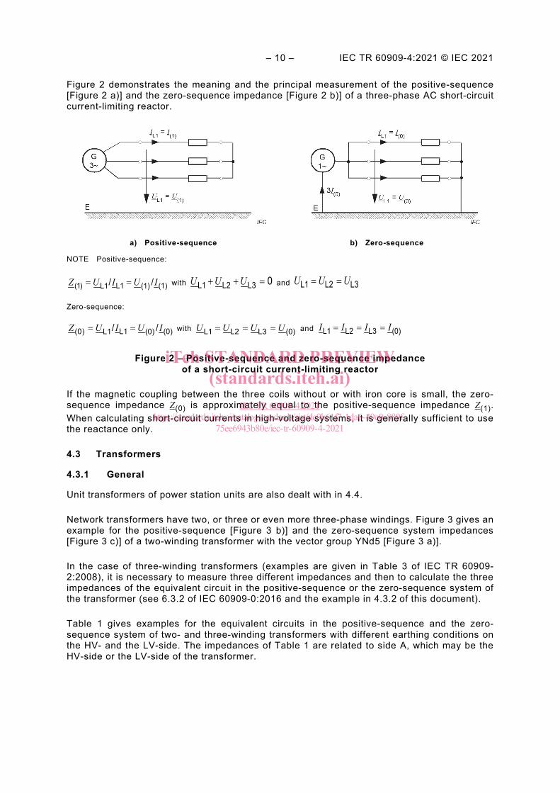
Figure 2 demonstrates the meaning and the principal measurement of the positive-sequence [Figure 2 a)] and the zero-sequence impedance [Figure 2 b)] of a three-phase AC short-circuit current-limiting reactor.
a) Positive-sequence b) Zero-sequence
NOTE Positive-sequence:
(1) L1 (1)L1 (1)/ /Z U I U I= = with U U U+ + =L1 L2 L3 0 and U U U= =L1 L2 L3
Zero-sequence:
(0) L1 (0)L1 (0)/ /Z U I U I= = with L1 L2 L3 (0)U U U U= = = and L1 L2 L3 (0)I I I I= = =
Figure 2 – Positive-sequence and zero-sequence impedance of a short-circuit current-limiting reactor
If the magnetic coupling between the three coils without or with iron core is small, the zero-sequence impedance Z(0) is approximately equal to the positive-sequence impedance Z(1). When calculating short-circuit currents in high-voltage systems, it is generally sufficient to use the reactance only.
4.3 Transformers
4.3.1 General
Unit transformers of power station units are also dealt with in 4.4.
Network transformers have two, or three or even more three-phase windings. Figure 3 gives an example for the positive-sequence [Figure 3 b)] and the zero-sequence system impedances [Figure 3 c)] of a two-winding transformer with the vector group YNd5 [Figure 3 a)].
In the case of three-winding transformers (examples are given in Table 3 of IEC TR 60909-2:2008), it is necessary to measure three different impedances and then to calculate the three impedances of the equivalent circuit in the positive-sequence or the zero-sequence system of the transformer (see 6.3.2 of IEC 60909-0:2016 and the example in 4.3.2 of this document).
Table 1 gives examples for the equivalent circuits in the positive-sequence and the zero-sequence system of two- and three-winding transformers with different earthing conditions on the HV- and the LV-side. The impedances of Table 1 are related to side A, which may be the HV-side or the LV-side of the transformer.
iTeh STANDARD PREVIEW(standards.iteh.ai)
IEC TR 60909-4:2021https://standards.iteh.ai/catalog/standards/sist/dc9b61f7-1da6-49e0-889f-
75ee6943b80e/iec-tr-60909-4-2021

IEC TR 60909-4:2021 © IEC 2021 – 11 –
a) Two-winding transformer with the terminals 1U,1V,1W at the high-voltage side and 2U,2V,2W at the low-voltage side
b) Positive-sequence and negative-sequence impedance Z(1) = Z(2)
c) Zero-sequence impedance Z(0)
a In the case of a delta winding, it is not necessary to introduce the short circuit and the earth connection.
Figure 3 – Positive-sequence and zero-sequence system impedances of a two-winding transformer YNd5
As shown in Table 2, transformers with the vector group Yy should not be used in low-voltage systems with low-impedance earthing on the LV-side (TN-network), because Z(0) may be very high, so that short-circuit protection may fail. For feeding TN-networks, transformers of no. 2 or 3 in Table 1 should be used.
Transformers with the vector group YNyn,d are typical in high-voltage networks, with neutral point earthing normally only on one side (A or B). The examples no. 4b and 6 of Table 1 show that the zero-sequence system of both networks are coupled, if both the neutral points A and B are earthed (earthing switch ES in case no. 4b closed). In these cases, additional considerations are necessary, especially if the transformation ratio is high, to find out if this coupling is admissible. Case no. 5 of Table 1 gives an example how to avoid this coupling in the zero-sequence system. Case no. 9 of Table 1 gives a further example to avoid the coupling in the zero-sequence system if two parallel transformers at the same place or at different places are present.
iTeh STANDARD PREVIEW(standards.iteh.ai)
IEC TR 60909-4:2021https://standards.iteh.ai/catalog/standards/sist/dc9b61f7-1da6-49e0-889f-
75ee6943b80e/iec-tr-60909-4-2021

– 12 – IEC TR 60909-4:2021 © IEC 2021
Table 1 – Examples for equivalent circuit-diagrams of transformers in the positive-sequence and the zero-sequence system
No. Vector group
Transformer Positive-sequence system
Zero-sequence system
1a YNy
a)
b)
1b YNy
a)
b)
2 Dyn
a)
b)
3 YNd
ZNy
ZNd
a)
b)
4a YNdy
c)
d)
iTeh STANDARD PREVIEW(standards.iteh.ai)
IEC TR 60909-4:2021https://standards.iteh.ai/catalog/standards/sist/dc9b61f7-1da6-49e0-889f-
75ee6943b80e/iec-tr-60909-4-2021

IEC TR 60909-4:2021 © IEC 2021 – 13 –
No. Vector group
Transformer Positive-sequence system
Zero-sequence system
4b YNdyn
e)
c)
d)
5 YNdz
c)
d)
6 YNdyn
f)
g)
7 YNdzn
f)
g)
iTeh STANDARD PREVIEW(standards.iteh.ai)
IEC TR 60909-4:2021https://standards.iteh.ai/catalog/standards/sist/dc9b61f7-1da6-49e0-889f-
75ee6943b80e/iec-tr-60909-4-2021