Edition 2.0 2016-06 INTERNATIONAL STANDARD NORME ...
15
IEC 61340-2-3 Edition 2.0 2016-06 INTERNATIONAL STANDARD NORME INTERNATIONALE Electrostatics – Part 2-3: Methods of test for determining the resistance and resistivity of solid materials used to avoid electrostatic charge accumulation Électrostatique – Partie 2-3: Méthodes d'essais pour la détermination de la résistance et de la résistivité des matériaux solides destinés à éviter les charges électrostatiques IEC 61340-2-3:2016-06(en-fr) ® iTeh STANDARD PREVIEW (standards.iteh.ai) IEC 61340-2-3:2016 https://standards.iteh.ai/catalog/standards/sist/d40def1d-b0f7-4527-8fe4- 3257f34aba7f/iec-61340-2-3-2016
Transcript of Edition 2.0 2016-06 INTERNATIONAL STANDARD NORME ...
IEC 61340-2-3 Edition 2.0 2016-06
INTERNATIONAL STANDARD NORME INTERNATIONALE
Electrostatics – Part 2-3: Methods of test for determining the resistance and resistivity of solid materials used to avoid electrostatic charge accumulation Électrostatique – Partie 2-3: Méthodes d'essais pour la détermination de la résistance et de la résistivité des matériaux solides destinés à éviter les charges électrostatiques
IEC
613
40-2
-3:2
016-
06(e
n-fr)
®
iTeh STANDARD PREVIEW(standards.iteh.ai)
IEC 61340-2-3:2016https://standards.iteh.ai/catalog/standards/sist/d40def1d-b0f7-4527-8fe4-
3257f34aba7f/iec-61340-2-3-2016
THIS PUBLICATION IS COPYRIGHT PROTECTED Copyright © 2016 IEC, Geneva, Switzerland All rights reserved. Unless otherwise specified, no part of this publication may be reproduced or utilized in any form or by any means, electronic or mechanical, including photocopying and microfilm, without permission in writing from either IEC or IEC's member National Committee in the country of the requester. If you have any questions about IEC copyright or have an enquiry about obtaining additional rights to this publication, please contact the address below or your local IEC member National Committee for further information. Droits de reproduction réservés. Sauf indication contraire, aucune partie de cette publication ne peut être reproduite ni utilisée sous quelque forme que ce soit et par aucun procédé, électronique ou mécanique, y compris la photocopie et les microfilms, sans l'accord écrit de l'IEC ou du Comité national de l'IEC du pays du demandeur. Si vous avez des questions sur le copyright de l'IEC ou si vous désirez obtenir des droits supplémentaires sur cette publication, utilisez les coordonnées ci-après ou contactez le Comité national de l'IEC de votre pays de résidence.
IEC Central Office Tel.: +41 22 919 02 11 3, rue de Varembé Fax: +41 22 919 03 00 CH-1211 Geneva 20 [email protected] Switzerland www.iec.ch
About the IEC The International Electrotechnical Commission (IEC) is the leading global organization that prepares and publishes International Standards for all electrical, electronic and related technologies. About IEC publications The technical content of IEC publications is kept under constant review by the IEC. Please make sure that you have the latest edition, a corrigenda or an amendment might have been published. IEC Catalogue - webstore.iec.ch/catalogue The stand-alone application for consulting the entire bibliographical information on IEC International Standards, Technical Specifications, Technical Reports and other documents. Available for PC, Mac OS, Android Tablets and iPad. IEC publications search - www.iec.ch/searchpub The advanced search enables to find IEC publications by a variety of criteria (reference number, text, technical committee,…). It also gives information on projects, replaced and withdrawn publications. IEC Just Published - webstore.iec.ch/justpublished Stay up to date on all new IEC publications. Just Published details all new publications released. Available online and also once a month by email.
Electropedia - www.electropedia.org The world's leading online dictionary of electronic and electrical terms containing 20 000 terms and definitions in English and French, with equivalent terms in 15 additional languages. Also known as the International Electrotechnical Vocabulary (IEV) online. IEC Glossary - std.iec.ch/glossary 65 000 electrotechnical terminology entries in English and French extracted from the Terms and Definitions clause of IEC publications issued since 2002. Some entries have been collected from earlier publications of IEC TC 37, 77, 86 and CISPR. IEC Customer Service Centre - webstore.iec.ch/csc If you wish to give us your feedback on this publication or need further assistance, please contact the Customer Service Centre: [email protected].
A propos de l'IEC La Commission Electrotechnique Internationale (IEC) est la première organisation mondiale qui élabore et publie des Normes internationales pour tout ce qui a trait à l'électricité, à l'électronique et aux technologies apparentées. A propos des publications IEC Le contenu technique des publications IEC est constamment revu. Veuillez vous assurer que vous possédez l’édition la plus récente, un corrigendum ou amendement peut avoir été publié. Catalogue IEC - webstore.iec.ch/catalogue Application autonome pour consulter tous les renseignements bibliographiques sur les Normes internationales, Spécifications techniques, Rapports techniques et autres documents de l'IEC. Disponible pour PC, Mac OS, tablettes Android et iPad. Recherche de publications IEC - www.iec.ch/searchpub La recherche avancée permet de trouver des publications IEC en utilisant différents critères (numéro de référence, texte, comité d’études,…). Elle donne aussi des informations sur les projets et les publications remplacées ou retirées. IEC Just Published - webstore.iec.ch/justpublished Restez informé sur les nouvelles publications IEC. Just Published détaille les nouvelles publications parues. Disponible en ligne et aussi une fois par mois par email.
Electropedia - www.electropedia.org Le premier dictionnaire en ligne de termes électroniques et électriques. Il contient 20 000 termes et définitions en anglais et en français, ainsi que les termes équivalents dans 15 langues additionnelles. Egalement appelé Vocabulaire Electrotechnique International (IEV) en ligne. Glossaire IEC - std.iec.ch/glossary 65 000 entrées terminologiques électrotechniques, en anglais et en français, extraites des articles Termes et Définitions des publications IEC parues depuis 2002. Plus certaines entrées antérieures extraites des publications des CE 37, 77, 86 et CISPR de l'IEC. Service Clients - webstore.iec.ch/csc Si vous désirez nous donner des commentaires sur cette publication ou si vous avez des questions contactez-nous: [email protected].
iTeh STANDARD PREVIEW(standards.iteh.ai)
IEC 61340-2-3:2016https://standards.iteh.ai/catalog/standards/sist/d40def1d-b0f7-4527-8fe4-
3257f34aba7f/iec-61340-2-3-2016

IEC 61340-2-3 Edition 2.0 2016-06
INTERNATIONAL STANDARD NORME INTERNATIONALE
Electrostatics – Part 2-3: Methods of test for determining the resistance and resistivity of solid materials used to avoid electrostatic charge accumulation Électrostatique – Partie 2-3: Méthodes d'essais pour la détermination de la résistance et de la résistivité des matériaux solides destinés à éviter les charges électrostatiques
INTERNATIONAL ELECTROTECHNICAL COMMISSION
COMMISSION ELECTROTECHNIQUE INTERNATIONALE ICS 17.220.99; 29.020
ISBN 978-2-8322-3475-4
® Registered trademark of the International Electrotechnical Commission Marque déposée de la Commission Electrotechnique Internationale
®
Warning! Make sure that you obtained this publication from an authorized distributor. Attention! Veuillez vous assurer que vous avez obtenu cette publication via un distributeur agréé.
iTeh STANDARD PREVIEW(standards.iteh.ai)
IEC 61340-2-3:2016https://standards.iteh.ai/catalog/standards/sist/d40def1d-b0f7-4527-8fe4-
3257f34aba7f/iec-61340-2-3-2016

– 2 – IEC 61340-2-3:2016 © IEC 2016
CONTENTS
FOREWORD ........................................................................................................................4 INTRODUCTION ..................................................................................................................6 1 Scope ...........................................................................................................................7 2 Normative references ....................................................................................................7 3 Terms and definitions ....................................................................................................7 4 Conditioning and test environment .................................................................................9 5 Selection of test method ................................................................................................9 6 Resistance measurements for solid conductive materials ............................................. 10 7 Resistance measurements for solid insulating materials ............................................... 10 8 Resistance measurements for planar electrostatic dissipative materials (used to
avoid electrostatic charge accumulation) ...................................................................... 10 8.1 Instrumentation ................................................................................................... 10
8.1.1 General ...................................................................................................... 10 8.1.2 Instrumentation for laboratory evaluation .................................................... 10 8.1.3 Instrumentation for acceptance testing ....................................................... 10 8.1.4 Instrumentation for compliance verification (periodic testing) ...................... 11
8.2 Electrode assemblies .......................................................................................... 11 8.2.1 General ...................................................................................................... 11 8.2.2 Assembly for the measurement of surface resistance.................................. 11 8.2.3 Assembly for the measurement of volume resistance .................................. 12 8.2.4 Assembly for the measurement of resistance to ground/groundable
point and point-to-point resistance ............................................................... 12 8.2.5 Test support ............................................................................................... 13
8.3 Sample preparation and handling ........................................................................ 13 8.4 Test procedures .................................................................................................. 14
8.4.1 Surface resistance measurements .............................................................. 14 8.4.2 Volume resistance measurements .............................................................. 14 8.4.3 Resistance to groundable point measurements ........................................... 15 8.4.4 Point-to-point resistance measurements ..................................................... 16
9 Conversion to resistivity values .................................................................................... 17 9.1 Surface resistivity ρs ........................................................................................... 17 9.2 Volume resistivity ρv ........................................................................................... 17
10 Resistance measurements for non-planar materials and products with small structures ................................................................................................................................... 18
10.1 General considerations ....................................................................................... 18 10.2 Equipment .......................................................................................................... 18
10.2.1 Probe ......................................................................................................... 18 10.2.2 Sample support surface ............................................................................. 20 10.2.3 Resistance measurement apparatus ........................................................... 20 10.2.4 Test leads .................................................................................................. 21
10.3 Test procedure .................................................................................................... 22 11 Repeatability and reproducibility .................................................................................. 22 12 Test report .................................................................................................................. 23 Annex A (normative) System verification ............................................................................ 25
A.1 System verification for surface resistance measurements .................................... 25
iTeh STANDARD PREVIEW(standards.iteh.ai)
IEC 61340-2-3:2016https://standards.iteh.ai/catalog/standards/sist/d40def1d-b0f7-4527-8fe4-
3257f34aba7f/iec-61340-2-3-2016

IEC 61340-2-3:2016 © IEC 2016 – 3 – –
A.1.1 Fixture and procedure for lower resistance range ....................................... 25 A.1.2 Fixture and procedure for upper resistance range and determination of
electrification period ..................................................................................... 26 A.2 System verification for volume resistance measurements .................................... 27
A.2.1 Fixture and procedure for lower resistance range ....................................... 27 A.2.2 Fixture and procedure for upper resistance range and determination of
electrification period ..................................................................................... 27 A.3 System verification for resistance measurements for non-planar materials
and products with small structures ...................................................................... 27 A.3.1 Verification fixtures .................................................................................... 27 A.3.2 Verification procedure ................................................................................ 28
Figure 1 – Example of an assembly for the measurement of surface and volume resistance........................................................................................................................... 12 Figure 2 – Example of an assembly for the measurement of resistance to ground/groundable point and point-to-point resistance ........................................................ 13 Figure 3 – Basic connections of the electrodes for surface resistance measurements ......... 14 Figure 4 – Basic connections of the electrodes for volume resistance measurements ......... 15 Figure 5 – Principle of resistance to groundable point measurements .................................. 16 Figure 6 – Principle of point-to-point measurements ............................................................ 17 Figure 7 – Configuration for the conversion to surface or volume resistivity ......................... 18 Figure 8 – Two-point probe configuration ............................................................................ 20 Figure 9 – Probe to instrumentation connection ................................................................... 21 Figure 10 – Spring compression for measurement ............................................................... 22 Figure A.1 – Lower resistance range verification fixture for surface resistance measurements .................................................................................................................... 25 Figure A.2 – Upper resistance range verification fixture for surface resistance measurements .................................................................................................................... 26 Figure A.3 – Resistance verification fixture ......................................................................... 28 Table 1 – Material for two-point probe ................................................................................. 19
iTeh STANDARD PREVIEW(standards.iteh.ai)
IEC 61340-2-3:2016https://standards.iteh.ai/catalog/standards/sist/d40def1d-b0f7-4527-8fe4-
3257f34aba7f/iec-61340-2-3-2016

– 4 – IEC 61340-2-3:2016 © IEC 2016
INTERNATIONAL ELECTROTECHNICAL COMMISSION
____________
ELECTROSTATICS –
Part 2-3: Methods of test for determining the resistance
and resistivity of solid materials used to avoid electrostatic charge accumulation
FOREWORD
1) The International Electrotechnical Commission (IEC) is a worldwide organization for standardization comprising all national electrotechnical committees (IEC National Committees). The object of IEC is to promote international co-operation on all questions concerning standardization in the electrical and electronic fields. To this end and in addition to other activities, IEC publishes International Standards, Technical Specifications, Technical Reports, Publicly Available Specifications (PAS) and Guides (hereafter referred to as “IEC Publication(s)”). Their preparation is entrusted to technical committees; any IEC National Committee interested in the subject dealt with may participate in this preparatory work. International, governmental and non-governmental organizations liaising with the IEC also participate in this preparation. IEC collaborates closely with the International Organization for Standardization (ISO) in accordance with conditions determined by agreement between the two organizations.
2) The formal decisions or agreements of IEC on technical matters express, as nearly as possible, an international consensus of opinion on the relevant subjects since each technical committee has representation from all interested IEC National Committees.
3) IEC Publications have the form of recommendations for international use and are accepted by IEC National Committees in that sense. While all reasonable efforts are made to ensure that the technical content of IEC Publications is accurate, IEC cannot be held responsible for the way in which they are used or for any misinterpretation by any end user.
4) In order to promote international uniformity, IEC National Committees undertake to apply IEC Publications transparently to the maximum extent possible in their national and regional publications. Any divergence between any IEC Publication and the corresponding national or regional publication shall be clearly indicated in the latter.
5) IEC itself does not provide any attestation of conformity. Independent certification bodies provide conformity assessment services and, in some areas, access to IEC marks of conformity. IEC is not responsible for any services carried out by independent certification bodies.
6) All users should ensure that they have the latest edition of this publication.
7) No liability shall attach to IEC or its directors, employees, servants or agents including individual experts and members of its technical committees and IEC National Committees for any personal injury, property damage or other damage of any nature whatsoever, whether direct or indirect, or for costs (including legal fees) and expenses arising out of the publication, use of, or reliance upon, this IEC Publication or any other IEC Publications.
8) Attention is drawn to the Normative references cited in this publication. Use of the referenced publications is indispensable for the correct application of this publication.
9) Attention is drawn to the possibility that some of the elements of this IEC Publication may be the subject of patent rights. IEC shall not be held responsible for identifying any or all such patent rights.
International Standard IEC 61340-2-3 has been prepared by IEC technical committee 101: Electrostatics.
This second edition cancels and replaces the first edition published in 2000. This edition constitutes a technical revision.
This edition includes the following significant technical changes with respect to the previous edition:
a) a distinction has been introduced between instrumentation used for laboratory evaluations, instrumentation used for acceptance testing and instrumentation used for compliance verification (periodic testing);
iTeh STANDARD PREVIEW(standards.iteh.ai)
IEC 61340-2-3:2016https://standards.iteh.ai/catalog/standards/sist/d40def1d-b0f7-4527-8fe4-
3257f34aba7f/iec-61340-2-3-2016
IEC 61340-2-3:2016 © IEC 2016 – 5 – – b) an alternative electrode assembly is described, which can be used on non-planar
products or when the dimensions of the product under test are too small to allow the larger electrode assembly to be used;
c) the formulae for calculating surface and volume resistivity have been modified to correspond with common industry practice in the main areas of application for the IEC 61340 series.
The text of this standard is based on the following documents:
CDV Report on voting
101/470/CDV 101/494/RVC
Full information on the voting for the approval of this standard can be found in the report on voting indicated in the above table.
This publication has been drafted in accordance with the ISO/IEC Directives, Part 2.
A list of all the parts in the IEC 61340 series, published under the general title Electrostatics, can be found on the IEC website.
The committee has decided that the contents of this publication will remain unchanged until the stability date indicated on the IEC website under "http://webstore.iec.ch" in the data related to the specific publication. At this date, the publication will be
• reconfirmed,
• withdrawn,
• replaced by a revised edition, or
• amended.
iTeh STANDARD PREVIEW(standards.iteh.ai)
IEC 61340-2-3:2016https://standards.iteh.ai/catalog/standards/sist/d40def1d-b0f7-4527-8fe4-
3257f34aba7f/iec-61340-2-3-2016
– 6 – IEC 61340-2-3:2016 © IEC 2016
INTRODUCTION
Measurements of resistances and related calculations of resistivities belong to the fundamental objectives of electrical measuring techniques along with measurements of voltage and current.
Resistivity is the electrical characteristic having the widest range, extending over some thirty orders of magnitude from the most conductive metal to almost perfect insulators.
The basis is Ohm's law and is valid for DC current and instantaneous values of AC current in electron conductors (metals, carbon, etc.). Values of resistance measurements using AC current can be influenced by capacitive/inductive reactance, depending on the frequency. Thus, existing national and international standards dealing with resistance measurements of solid materials normally require the application of DC current.
Most non-metal materials such as plastics are classified as polymers and ion conductors. The transport of charges can be dependent upon the applied electrical field strength during the measurement. Beside the measuring current, there exists a charging current that polarizes and/or electrostatically charges the material, indicated by an asymptotic decay of the measuring current with time and causing an apparent change in resistance. If this effect is observed, it will be advisable to repeat the measurement immediately after a definite electrification time has elapsed using the reverse polarity for the measuring current and averaging both obtained values.
iTeh STANDARD PREVIEW(standards.iteh.ai)
IEC 61340-2-3:2016https://standards.iteh.ai/catalog/standards/sist/d40def1d-b0f7-4527-8fe4-
3257f34aba7f/iec-61340-2-3-2016

IEC 61340-2-3:2016 © IEC 2016 – 7 – –
ELECTROSTATICS –
Part 2-3: Methods of test for determining the resistance and resistivity of solid materials used
to avoid electrostatic charge accumulation
1 Scope
This part of IEC 61340 describes test methods for the determination of the electrical resistance and resistivity of solid materials used to avoid electrostatic charge accumulation, in which the measured resistance is in the range 104 Ω to 1012 Ω.
It takes account of existing IEC/ISO standards and other published information, and gives recommendations and guidelines on the appropriate method.
2 Normative references
The following documents, in whole or in part, are normatively referenced in this document and are indispensable for its application. For dated references, only the edition cited applies. For undated references, the latest edition of the referenced document (including any amendments) applies.
IEC 62631-3-1, Dielectric and resistive properties of solid insulating materials – Part 3-1: Determination of resistive properties (DC Methods) – Volume resistance and volume resistivity – General method
IEC 62631-3-2, Dielectric and resistive properties of solid insulating materials – Part 3-2: Determination of resistive properties (DC Methods) – Surface resistance and surface resistivity
IEC 62631-3-3, Dielectric and resistive properties of solid insulating materials – Part 3-3: Determination of resistive properties (DC Methods) – Insulation resistance
ISO 1853, Conducting and dissipative rubbers, vulcanized or thermoplastic – Measurement of resistivity
ISO 2951, Rubber, vulcanized or thermoplastic – Determination of insulation resistance
ISO 3915, Plastics – Measurement of resistivity of conductive plastics
ISO 7619-1, Rubber, vulcanized or thermoplastic – Determination of indentation hardness – Part 1: Durometer method (Shore hardness)
3 Terms and definitions
For the purposes of this document, the following terms and definitions apply:
3.1 electrode conductor of defined shape, size and configuration being in contact with the specimen to be measured
iTeh STANDARD PREVIEW(standards.iteh.ai)
IEC 61340-2-3:2016https://standards.iteh.ai/catalog/standards/sist/d40def1d-b0f7-4527-8fe4-
3257f34aba7f/iec-61340-2-3-2016
– 8 – IEC 61340-2-3:2016 © IEC 2016
3.2 resistance R ratio of a DC voltage (V) applied between two points and the steady-state current (A) between the two points
Note 1 to entry: Resistance is expressed in ohms.
3.3 resistance to ground Rg resistance measured between an electrode placed on the surface of a test specimen and a local ground
Note 1 to entry: Resistance to ground is expressed in ohms.
3.4 resistance to groundable point Rgp resistance measured between an electrode placed on the surface of a test specimen and a groundable point fitted to the test specimen
Note 1 to entry: Resistance to groundable point is expressed in ohms.
3.5 point-to-point resistance Rpp resistance measured between two electrodes placed a specified distance apart on the same surface of a test specimen
Note 1 to entry: Point-to-point resistance is expressed in ohms.
3.6 surface resistance Rs resistance measured between a central disc electrode and a surrounding concentric ring electrode placed on the surface of a test specimen
Note 1 to entry: Surface resistance is expressed in ohms.
3.7 surface resistivity ρs resistivity equivalent to the surface resistance of a square area, having the electrodes at two opposite sides
Note 1 to entry: The SI unit of surface resistivity (Ω) is sometimes referred to as Ω/sq (ohms per square), to distinguish resistivity values from resistance values. However, the use of Ω/sq is deprecated because it may imply a resistance per unit area, which is not correct.
3.8 volume resistance Rv resistance measured between two electrodes placed on opposite surfaces of a test specimen
Note 1 to entry: Volume resistance is expressed in ohms.
iTeh STANDARD PREVIEW(standards.iteh.ai)
IEC 61340-2-3:2016https://standards.iteh.ai/catalog/standards/sist/d40def1d-b0f7-4527-8fe4-
3257f34aba7f/iec-61340-2-3-2016
IEC 61340-2-3:2016 © IEC 2016 – 9 – –
3.9 volume resistivity ρv ratio of a DC field strength (V/m) and the steady-state current density (A/m2) within the material
Note 1 to entry: In practice, it is equivalent to the volume resistance of a cube with unit length, having the electrodes at two opposite surfaces.
Note 2 to entry: Volume resistivity is not an appropriate characteristic for materials that are electrically inhomogeneous.
Note 3 to entry: Volume resistivity is expressed in ohm meters.
4 Conditioning and test environment
The electrostatic behaviour of materials is influenced by environmental conditions, such as relative humidity and temperature.
For this reason, measurements shall be performed under controlled conditions. The selection of the appropriate conditions for testing shall be decided according to the type of material (product specification) and the intended application, based on the most severe conditions expected to occur during usage (e.g. lowest humidity and highest humidity).
Unless otherwise agreed, the atmosphere for conditioning and testing shall be (23 ± 2) °C and (12 ± 3) % relative humidity, and the conditioning time prior to testing shall be at least 24 h.
If it is required to test that the measured resistance is not below a minimum limit, additional testing at high humidity is required. Unless otherwise agreed, the atmosphere for conditioning and testing at high humidity shall be (23 ± 2) °C and (60 ± 10) % relative humidity, and the conditioning time prior to testing shall be at least 24 h.
Specimens shall normally be conditioned and measured in the same climate, if not specified differently. However, preconditioning may be necessary in order to eliminate the effects of stress appearing after the moulding process of some plastic materials or as a drying treatment before the test procedure starts. Preconditioning is normally done in a different environment.
Adequate devices are a desiccator in an oven or a climate chamber preferably equipped with forced circulation and interchange of air.
5 Selection of test method
For planar materials, the following procedure shall be used to select the test method:
a) if the range of electrical resistance of a material to be tested is known, then use the relevant clause (Clause 6, 7, 8 or 10) where appropriate standards are listed or methods described;
b) for a material of initially unknown resistivity, start the measurements by using methods for conductive materials according to Clause 6.
If the measurement is not possible or the obtained result exceeds the given range for the application of the test method, it shall be regarded as being inadequate and the result shall not be taken into account. The measurement shall be repeated according to Clause 8 or Clause 10 for electrostatic dissipative materials. If the situation described above occurs again, the measurement shall be repeated according to Clause 7 for insulating materials.
iTeh STANDARD PREVIEW(standards.iteh.ai)
IEC 61340-2-3:2016https://standards.iteh.ai/catalog/standards/sist/d40def1d-b0f7-4527-8fe4-
3257f34aba7f/iec-61340-2-3-2016

– 10 – IEC 61340-2-3:2016 © IEC 2016
For non-planar materials and for products with structures that are too small to allow the use of the electrode assemblies specified in 8.2, the method described in Clause 10 shall be used.
If the measurement result using the method described in Clause 10 is less than 104 Ω or greater than 1012 Ω, and the shape or dimensions of the material under test do not allow measurements according to Clause 6 or Clause 7, the test result shall be reported as either “<104 Ω” or “>1012 Ω”.
6 Resistance measurements for solid conductive materials
The resistance of solid conductive materials (non-metals) shall be measured in accordance with ISO 3915 for plastics or ISO 1853 for rubbers. If the measured resistance is greater than or equal to 104 Ω, use the methods described in Clause 7, 8 or 10.
7 Resistance measurements for solid insulating materials
The resistance of solid insulating materials shall be measured in accordance with IEC 62631-3-1, IEC 62631-3-2 or IEC 62631-3-3 for plastics, or ISO 2951 for rubbers.
8 Resistance measurements for planar electrostatic dissipative materials (used to avoid electrostatic charge accumulation)
8.1 Instrumentation
8.1.1 General
The instrumentation may consist of either a DC power supply and an ammeter, or an integrated instrument (ohmmeter). National safety regulations shall be followed.
8.1.2 Instrumentation for laboratory evaluation
The output voltage under load shall be (100 ± 5) V for measurements of 1 × 10⁶ Ω and higher, and (10,0 ± 0,5) V for less than 1 × 10⁶ Ω.
If an ohmmeter is used, readings shall be possible at least from 1 × 10³ Ω to 1 × 10¹³ Ω, with an accuracy of ±10 %.
If a DC power supply and ammeter are used, readings shall be possible at least from 10 pA to 10 mA. The combined accuracy of the DC power supply and ammeter shall be ±10 %.
8.1.3 Instrumentation for acceptance testing
Instrumentation for laboratory evaluation or instrumentation meeting the following requirements shall be used for acceptance testing.
The open circuit voltage shall be (100 ± 5) V for measurements of 1 × 10⁶ Ω and higher, and (10,0 ± 0,5) V for less than 1 × 10⁶ Ω.
If an ohmmeter is used, readings shall be possible at least from 1 × 10³ Ω to 1 × 10¹³ Ω, with an accuracy of ±20 %.
If a DC power supply and ammeter are used, readings shall be possible at least from 10 pA to 10 mA with an accuracy of ±20 %.
iTeh STANDARD PREVIEW(standards.iteh.ai)
IEC 61340-2-3:2016https://standards.iteh.ai/catalog/standards/sist/d40def1d-b0f7-4527-8fe4-
3257f34aba7f/iec-61340-2-3-2016
IEC 61340-2-3:2016 © IEC 2016 – 11 – – In case of dispute, instrumentation for laboratory evaluations shall be used.
8.1.4 Instrumentation for compliance verification (periodic testing)
Instrumentation meeting the requirements for laboratory evaluations or acceptance testing, or instrumentation meeting the following requirements shall be used.
Compliance verification instrumentation shall be capable of making measurements one order of magnitude above and below the intended measurement range. The output voltage of compliance verification instrumentation may vary from laboratory evaluation or acceptance testing instrumentation, and may be rated under load or open circuit. Compliance verification instrumentation shall be checked against laboratory evaluation or acceptance testing instrumentation to ensure there is correlation between measurement results.
In case of dispute, instrumentation for acceptance testing or laboratory evaluation shall be used.
8.2 Electrode assemblies
8.2.1 General
The electrodes shall consist of a material that allows intimate contact with the specimen surface and introduces no appreciable error because of electrode resistance or contamination of the specimen. The electrode material shall be corrosion resistant under test conditions and shall not cause a chemical reaction with the material being tested.
The assemblies described in the subclauses below are recommended to be suitable, but other configurations complying with national or international standards may also be used, if appropriate. Especially for volume resistance measurements of electrostatic dissipative materials, it is important that applied probes of the guarded ring type have sufficient space between the centre (measuring) and ring (guard) contact electrode in order to minimize stray currents falsifying the readings. It is recommended, that the gap g shall be at least 10 mm. In cases of dispute, the assemblies described in this standard shall be applied.
8.2.2 Assembly for the measurement of surface resistance
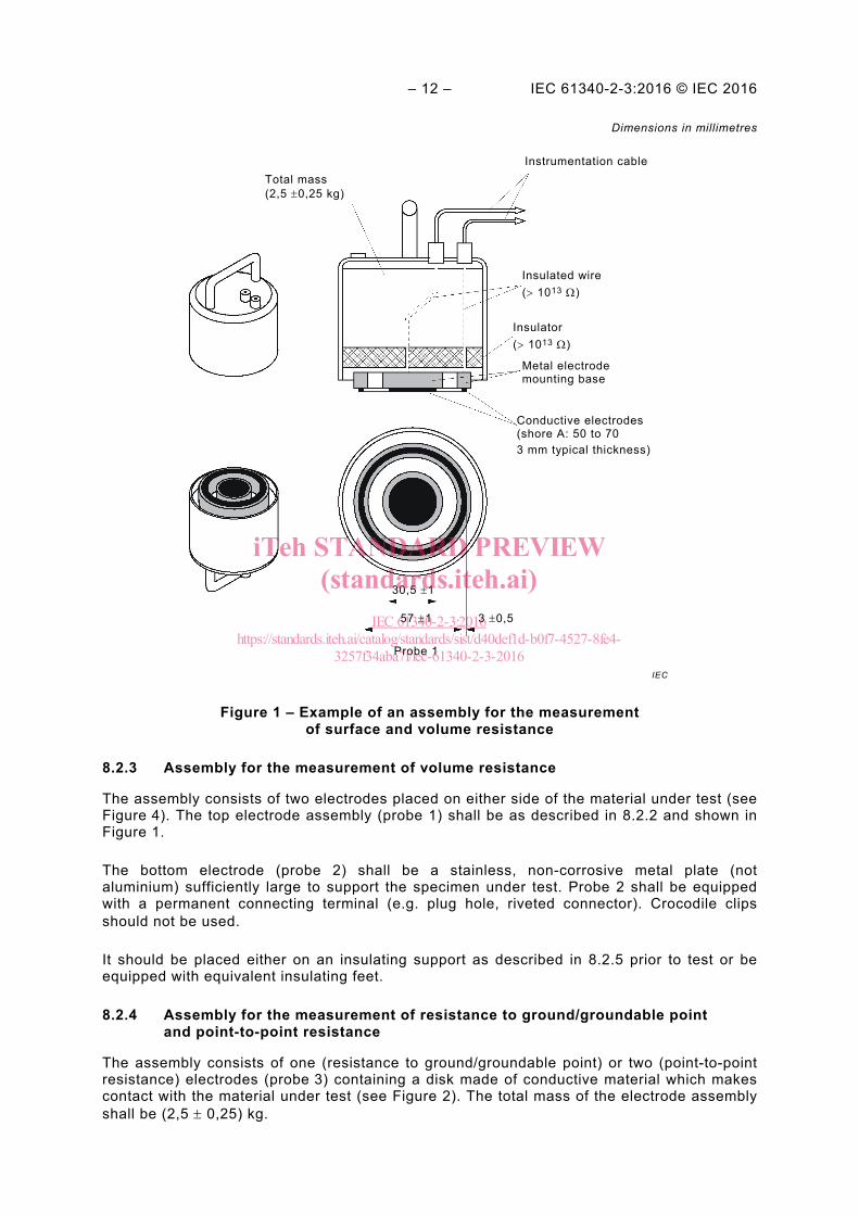
The electrode assembly (probe 1) contains a central disc surrounded by a concentric ring made of conductive materials which make contact with the material under test (see Figure 1). The total mass of the electrode assembly shall be (2,5 ± 0,25) kg.
The contact surface material shall have a volume resistance of less than 103 Ω when tested on a stainless, non-corrosive metal plate (not aluminium) as the counter electrode by applying (10,0 ± 0,5) V, and shall have a Shore A hardness of 50 to 70 when tested according to ISO 7619-1.
Insulating materials used in the electrode assembly shall have volume and/or surface resistance greater than 1013 Ω when tested according to IEC 62631-3-1 and/or IEC 62631-3-2 respectively.
The material under test shall be placed on an insulating support as described in 8.2.5.
iTeh STANDARD PREVIEW(standards.iteh.ai)
IEC 61340-2-3:2016https://standards.iteh.ai/catalog/standards/sist/d40def1d-b0f7-4527-8fe4-
3257f34aba7f/iec-61340-2-3-2016
– 12 – IEC 61340-2-3:2016 © IEC 2016
Dimensions in millimetres
Figure 1 – Example of an assembly for the measurement of surface and volume resistance
8.2.3 Assembly for the measurement of volume resistance
The assembly consists of two electrodes placed on either side of the material under test (see Figure 4). The top electrode assembly (probe 1) shall be as described in 8.2.2 and shown in Figure 1.
The bottom electrode (probe 2) shall be a stainless, non-corrosive metal plate (not aluminium) sufficiently large to support the specimen under test. Probe 2 shall be equipped with a permanent connecting terminal (e.g. plug hole, riveted connector). Crocodile clips should not be used.
It should be placed either on an insulating support as described in 8.2.5 prior to test or be equipped with equivalent insulating feet.
8.2.4 Assembly for the measurement of resistance to ground/groundable point and point-to-point resistance
The assembly consists of one (resistance to ground/groundable point) or two (point-to-point resistance) electrodes (probe 3) containing a disk made of conductive material which makes contact with the material under test (see Figure 2). The total mass of the electrode assembly shall be (2,5 ± 0,25) kg.
IEC
Instrumentation cable Total mass (2,5 ±0,25 kg)
Insulated wire (> 1013 Ω)
Insulator (> 1013 Ω)
Metal electrode mounting base
Conductive electrodes (shore A: 50 to 70 3 mm typical thickness)
30,5 ±1 57 ±1 3 ±0,5
Probe 1
iTeh STANDARD PREVIEW(standards.iteh.ai)
IEC 61340-2-3:2016https://standards.iteh.ai/catalog/standards/sist/d40def1d-b0f7-4527-8fe4-
3257f34aba7f/iec-61340-2-3-2016

IEC 61340-2-3:2016 © IEC 2016 – 13 – – The contact surface material shall be conductive enough that two probes placed on a metal surface (e.g. probe 2) have a point-to-point resistance of less than 103 Ω when tested with (10,0 ± 0,5) V, and shall have a Shore A hardness of 50 to 70 when tested according to ISO 7619-1.
Insulating materials used in the electrode assembly shall have volume and/or surface resistance greater than 1013 Ω when tested according to IEC 62631-3-1 and/or IEC 62631-3-2 respectively.
The material under test shall be placed on an insulating support as described in 8.2.5.
Dimensions in millimetres
Figure 2 – Example of an assembly for the measurement of resistance to ground/groundable point and point-to-point resistance
8.2.5 Test support
The material shall be tested on a smooth flat support having a surface resistance greater than 1 × 10¹³ Ω, measured according to IEC 62631-3-2. The size shall be at least 10 mm more in length and width compared to the size of the specimen under test. The minimum thickness shall be 1 mm.
8.3 Sample preparation and handling
Refer to applicable material specifications for sampling instructions. The specimens shall not be handled or marked in areas where measurements will be performed. If the areas where
IEC
Total mass (2,5 ± 0,25 kg)
Insulated wire (> 1013 Ω)
Insulator (> 1013 Ω)
Metal electrode mounting base
Conductive electrodes (shore A: 50 to 70 3 mm typical thickness)
63,5 ±1 Probe 3
Instrumentation cable
iTeh STANDARD PREVIEW(standards.iteh.ai)
IEC 61340-2-3:2016https://standards.iteh.ai/catalog/standards/sist/d40def1d-b0f7-4527-8fe4-
3257f34aba7f/iec-61340-2-3-2016