edge.rit.eduedge.rit.edu/content/P16603/public/Subsystem Design... · Web viewNo set increment,...
16
P16601 Questions for Wayne 1. Why American made parts? a. ‘Made in America’ part requirement is for patriotic reasons but Glass Fab has also had excellent experience with the overall quality of American made parts; they feel they last longer and are of a superior quality than oversees parts (especially gears, bearings, etc). Parts will have much longer life. 2. Why did the previous attempt fail? a. Machine designed by the owner. He made a blade rather than wire machine. b. He rocked the blades (Wayne believes this was the mistake because for the material they cut rocking isn’t needed and straight plunge cutting is the way to go) c. They weren’t able to tension the blades d. The created a ‘package’ of 40 blades to perform the cuts but because they couldn’t tension them they could never get 40 parallel even parts 3. How Many Pitch Settings? a. Run from 1.31mm to 6.7mm part size and 1.515mm to 6.9mm pitch b. No set increment, depends on project. 4. How many cuts do you want? a. Rather than number of cuts, design to 400mm roller length. b. 400mm is flexible, but is based on half of current machine and a good starting value. It was the number he said several times. 5. What ingot size do you want? a. 220x220 cross sectional area. b. Length of rollers for workpiece length. 6. Precision of motors. a. Unknown, Wayne did not know this. b. Something we can probably design an experiment for. 7. Roller Schematics. a. Unknown. Whatever he has is in flash drive we were given. 8. Questions and Concerns
Transcript of edge.rit.eduedge.rit.edu/content/P16603/public/Subsystem Design... · Web viewNo set increment,...

P16601Questions for Wayne
1. Why American made parts?a. ‘Made in America’ part requirement is for patriotic reasons but Glass Fab has
also had excellent experience with the overall quality of American made parts; they feel they last longer and are of a superior quality than oversees parts (especially gears, bearings, etc). Parts will have much longer life.
2. Why did the previous attempt fail?a. Machine designed by the owner. He made a blade rather than wire machine.b. He rocked the blades (Wayne believes this was the mistake because for the
material they cut rocking isn’t needed and straight plunge cutting is the way to go)
c. They weren’t able to tension the bladesd. The created a ‘package’ of 40 blades to perform the cuts but because they
couldn’t tension them they could never get 40 parallel even parts3. How Many Pitch Settings?
a. Run from 1.31mm to 6.7mm part size and 1.515mm to 6.9mm pitchb. No set increment, depends on project.
4. How many cuts do you want?a. Rather than number of cuts, design to 400mm roller length.b. 400mm is flexible, but is based on half of current machine and a good starting
value. It was the number he said several times.5. What ingot size do you want?
a. 220x220 cross sectional area.b. Length of rollers for workpiece length.
6. Precision of motors.a. Unknown, Wayne did not know this.b. Something we can probably design an experiment for.
7. Roller Schematics.a. Unknown. Whatever he has is in flash drive we were given.
8. Questions and Concernsa. Don’t worry about coolant, it is unnecessary.b. Hardest issue to fix is software issues.c. Meyer Burger keeps a micron of accuracy.
Questions for Ray1. Do the rollers have two separate motors?
a. Yes, one for each roller2. Do you have to replace the coolant? If so, how often?
a. The coolant has not been replaced3. How are the rollers mounted?
a. One long rod through the middle clamps the bearings in and acts as a central alignment
b. 4 pins are used for alignment

c. Pull one side of machine out, install onto other side, push first side back in4. How are the motors connected to the rollers?
a. Direct driveb. No apparent gearbox
5. ADDITIONAL FINDINGS from seeing machine and talking with Raya. The coolant does not flow through the rollers at allb. Ray believes the coolant is for the bearings/motorsc. Ray likes to run at 12 m/sd. Ray judges the proper feed rate by watching the bow in the wire, aims for about a
2mm bowe. Machine will figure out time and wire consumption for a job based on inputsf. Tension is measured from the dancersg. Quartz and Pyrex are the main materials (hard glass)h. If the thickness they need does not exactly match a thickness that the rollers do,
they will do a small grinding step after
Measurements- Inner bars used for roller storage come out during installation. “Stretchable” bar through
middle for 700 Bar pressure acts as torque spec for rollers.- Rollers don’t receive any coolant on the inside.- Cooling “jackets” around bearings and motors according to Tom. Agrees with machine
schematics where it monitors static and movable bearing temperature.- about 0.55” or 14 mm of coating thickness adds to final rollers diameter of approximately
320 mm as stated in the specs.- Approximately 11.4” (290 mm) diameter of metal roller excluding coating.- Rollers mostly solid with about 1.25 to 1.5 inches of hollow diameter through the center.- According to Tom, upon roller installation, precise roller specifications are input into the
machine so it can calibrate.- Roller grooves are also not reversible or symmetrical.- 4 alignment holes for pins on each side of the roller, but with slightly different spacing on
each side so that the rollers cannot be put in reverse. - Rollers essentially connect to movable and static bearing through the pins and inner
alignment rod. Torque is applied on the outside of diameter rather than straight in the middle.
- Static bearing is next to the motors and does not move when rollers are removed/installed.
- Movable bearing slides out so that rollers can be removed from the side.- 2 threaded holes opposite one another on each side of roller, but reason is unclear.- Mechanical drawings found on flash drive files with dimensions of guide roller assembly- Rollers are responsible for the cutting force, not the wire spool team!
Movable Bearing

Coolant for Bearings
4 pins and two threaded rods

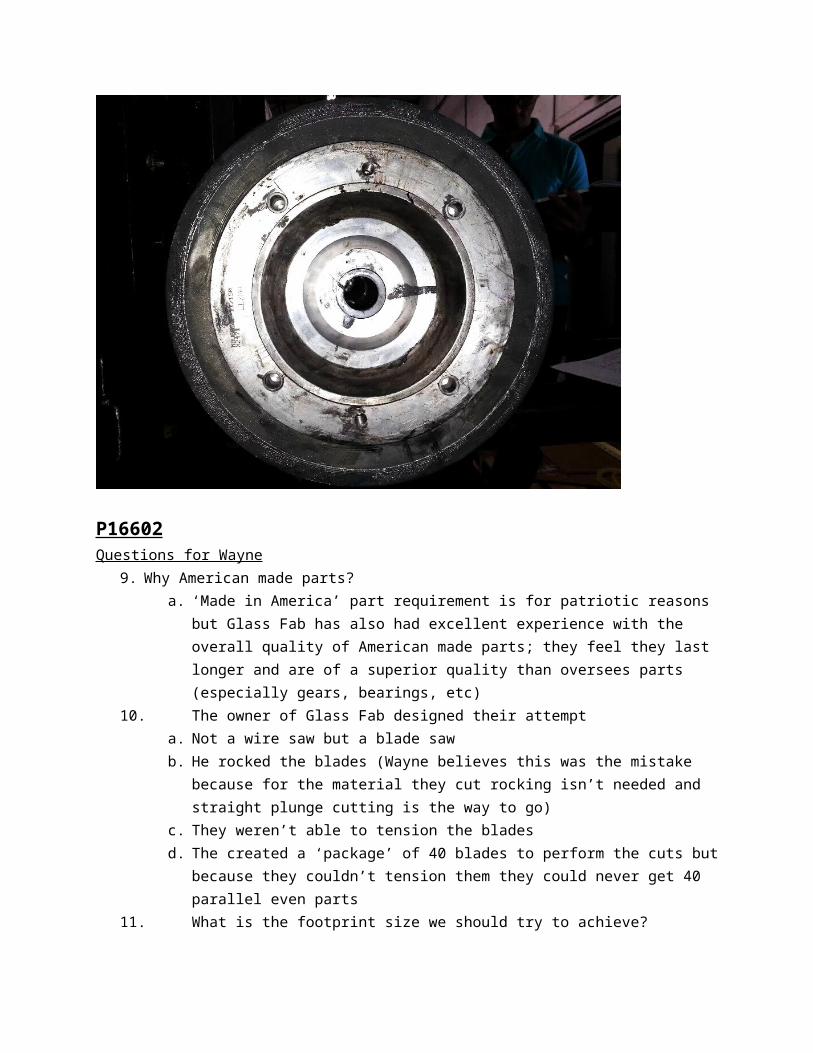
P16602Questions for Wayne
9. Why American made parts?a. ‘Made in America’ part requirement is for patriotic reasons but Glass Fab has
also had excellent experience with the overall quality of American made parts; they feel they last longer and are of a superior quality than oversees parts (especially gears, bearings, etc)
10. The owner of Glass Fab designed their attempta. Not a wire saw but a blade sawb. He rocked the blades (Wayne believes this was the mistake because for the
material they cut rocking isn’t needed and straight plunge cutting is the way to go)
c. They weren’t able to tension the bladesd. The created a ‘package’ of 40 blades to perform the cuts but because they
couldn’t tension them they could never get 40 parallel even parts11. What is the footprint size we should try to achieve?
a. For the footprint Wayne wouldn’t give us a number for the maximum footprint size of the new machine, just smaller than the Meyer Burger
b. Ed suggested created stretch goals:i. Max = 50% of the Meyer Burger sq. ft.ii. Goal = 25% of the Meyer Burger sq. ft.iii. Min = 20% of the Meyer Burger sq. ft.
c. We are also not constrained on the layout of the machine (we can make it long and skinny or a square shape and anything in between)
12. Where will the machine go in the facility?a. Glass Fab doesn’t have a specified spot for the new machine on the shop floor
yet.b. Overall weight of the new machine is a potential issuec. Goal is to considerably cut the weight compared to the Meyer Burgerd. Worst case nothing heavier than the current machine
13. How is the wire indexing rate calculated or is one setting for all jobsa. Wire indexing is an adjustable value: Meyer Burger gave Glass Fab a
recommended value and that is what they useb. But we could play around with this valuec. The operator controls how much wire goes forward and how much goes back
(400 m out and 395 m back)14. Do you want to optimize the use of the wire?
a. Glass Fab pays $3.50 (possibly a little less than that) per km of wireb. 475 km of wire per supply spoolc. Optimization of wire isn’t super important but they would like us to scale
appropriately with the changes we maked. Wire isn’t reusable once it is on the takeup spool
15. What type of pulley does the Meyer Burger machine use?a. The DS264 has metal pulleys with nylon (hard rubber) insertsb. These inserts are relatively cheapc. They replace the inserts on the DS264 about every other monthd. There are 2 different sizes of pulley inserts on the DS264
16. What is the power reduction that you are looking for?a. For our machine Wayne would like to cut everything at least in half (power
consumption, guide rollers, machine footprint, etc.) but Wayne doesn’t want to cut the size of the spool in half
17. How long do the spools last and do you want us to scale them down accordingly with the machine?
a. Right now the spools last them about 3 months, so we’d want to keep that the same as if we scale the spools down, then they should still last the same time
b. Scale down the spool size and the amount of wire on the spools to meet their routine maintenance period
c.18. What is the maximum ingot size?
a. Max ingot size of 220mm by 220mm19. How many cuts would you like this machine to do?
a. Number of cuts to range from 50 to 27020. What is the diameter of the wire?
a. The wire they currently use has a diameter of .175mm

Questions for Ray1. Is the wire indexing rate a calculated value or is one setting for all jobs?
a. Can be set between 500m and 300mb. Ability to change is importantc. Is 400m forward 395m back / was 500m forward 495m back (Ray just found a
value he liked)d. *this could be an opportunity for good technical analysis to develop a function of
workpiece width or volume to give index rate2. How much does the wire bounce up and down as it travels through the machine?
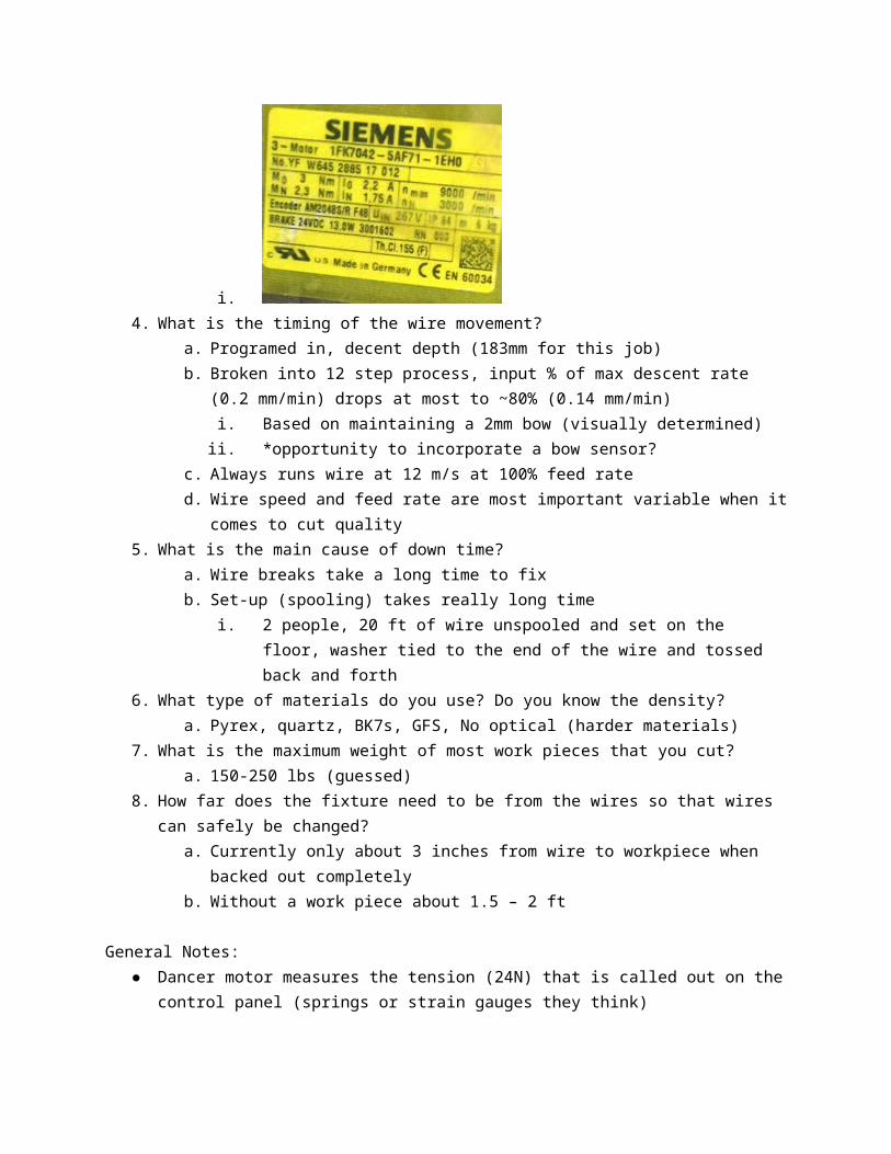
a. No visible bounce?3. What motor is being used for spool movement? (see it)
a. Pay-off spool model nameplate
i.b. Take up spool motor nameplate
i.

c. Motor for dancer
i.d. Motor for spooling pulley
i.4. What is the timing of the wire movement?
a. Programed in, decent depth (183mm for this job)b. Broken into 12 step process, input % of max descent rate (0.2 mm/min) drops at
most to ~80% (0.14 mm/min)i. Based on maintaining a 2mm bow (visually determined)ii. *opportunity to incorporate a bow sensor?
c. Always runs wire at 12 m/s at 100% feed rated. Wire speed and feed rate are most important variable when it comes to cut
quality5. What is the main cause of down time?
a. Wire breaks take a long time to fixb. Set-up (spooling) takes really long time
i. 2 people, 20 ft of wire unspooled and set on the floor, washer tied to the end of the wire and tossed back and forth
6. What type of materials do you use? Do you know the density?a. Pyrex, quartz, BK7s, GFS, No optical (harder materials)
7. What is the maximum weight of most work pieces that you cut?a. 150-250 lbs (guessed)
8. How far does the fixture need to be from the wires so that wires can safely be changed?a. Currently only about 3 inches from wire to workpiece when backed out
completelyb. Without a work piece about 1.5 – 2 ft
General Notes:

● Dancer motor measures the tension (24N) that is called out on the control panel (springs or strain gauges they think)
● Thin cut jobs often have at least one piece break away and fall onto the wire, this breaks the wire often
○ * opportunity to design tray to go under workpiece but above bottom wires to catch falling pieces (mesh to let slurry through)
● Lift cart is used to mount the workpiece● Ray uses zip ties to hold dancer in upright position during set-up● Dancer moves about +/- 0.5 in at steady state conditions, moves about +/- 2 or 3 in
during direction reversal process● Machine alarms and stops if dancer is too far off from vertical ● While the machine can run at a max wire speed of 15 m/s, Ray usually runs it at 12 m/s● Ray usually only configures the feed distance before starting? (although other
parameters are configurable)● Machine calculates most variables at runtime● Should allow user-controlled cut speed● Motor drives in cabinet next to PLC
○ Wires coming out ~ 1” diameter○ Manufactured by Siemens○ 8-segment displays with some programmable number - not sure what it
correlates to● Fixed acceleration of 2 m/s^2● Machine displays prompts for faults - i.e. dirty filter, wire break● 600 grit slurry used● Tension measured with dancer pulleys & springs (usually ~25N) and 10-12N in running
mode● There is slurry over everything!● The wire just wraps straight around the spools. There is no fancy wrap pattern.● The tension of the wire wrapping around the supply spool stretches out the spool
lengthwise.● The spooling pulley is synchronized with the rotation of the spool.● The tensioning pulley compensates the most during acceleration and deceleration.● The guide rollers are set up by tying a washer to the wire and throwing it across the
machine.● The wire rubs against the sides of the spool when spooling.● Tension while running was 24.93-25.12● Spool of new wire weighs 197.733 pounds.● Wire from Bekaert Corporation.
P166031. Why didn't the machine Glass Fab attempted to build work?
a. Attempted machine was designed by Glass Fab owner, Bobb. Used a band saw rather than wire sawc. Couldn't ever cut anything with it because the tension was never correct, blades were
never paralleld. Major mistake was the rocking, rocking is beneficial with harder materials but for the
materials Glass Fab has to cut, rocking was not necessarye. Blades had electro-plated diamondf. Machine used coolantg. Cutting area was always flooded with coolant
2. How important is the parallelism of the glass to the wires? What sort of tolerances is there on thickness, flatness, ect ..?
a. Glass Fab wants a very similar work piece movement system to what they have nowb. Parallelism is not very important due to their dove tail fixture contraptionc. The system they have now works and they'd like to have the new system have the dove tail
contraption as welld. There is a lot of variation in the way Ray mounts the work piece onto the fixture but it's ok
because the dove tail contraption is insurance that it will be parallel enough for their products3. What types of materials do you use? Densities of those materials for weight purposes?
a. Quartzb. BK7 c. Fused Silica d. Borosilicate
4. What's the vertical velocity profile look like? Is it constant? How much time does it take to accelerate up to speed?
a. For workpieces with a circular cross section, the speeds changes as the workpiece is cut to compensate for more glass being cut at the center of the workpiece compared to the edge of the workpiece.
b. Constant for rectangular cross sections.5. What is the maximum weight of most of the work pieces that you cut?6. How far does fixture need to be from the wires so that wires can safely be changed?
a. They've never changed the wires while a work piece is in the machineb. Assume that the minimum amount of space necessary is the max size of the work piece: 220 mm
7. Specifically what epoxy do you currently use?8. What is the tolerance for placing the workpiece on the fixture?
Supply spool
0.6”
13.7”6.4”
Takeup spool
2”17.3
?

a. There is a lot of variation in the way Ray mounts the work piece onto the fixture but it's ok because the dove tail contraption is insurance that it will be parallel enough for their products
9. How Ray mounts and orients the work piece on the current fixture? (Take a video if possible)10. The user interface/software11. The controller (siemens?)
a. siemens12. Normal and tangential forces13. Density and potentially hardness of materials14. Dimensions of different work pieces15. Dimensions of failed machine
a. 80in x 31in x 56in (L x W x H) 16. Take pictures of failed machine17. Take pictures of the DS264
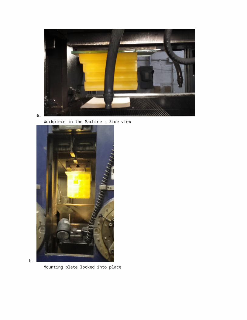
a.Workpiece in the Machine - Side view

b. Mounting plate locked into place
c. Machine mount without workpiece

d. A used sacrificial glass piece
e. Dove tail mount and sacrificial glass
18. Take pictures of DS264 interfacea. Screenshots on flash drive provided by glass fab
19. Take pictures of any fixture movement that is visiblea. Video in 16603 - Glass Fab Pictures folder
20. Measure how much the cutting wire bows when under the weight of the workpiece.a. 2mm - 3mmb. The speed of the workpiece is manually adjusted to keep the bow of the wire at 2mm - 3mm.
c. The sacrificial glass pieces were .5in thick and had cuts approximately 3mm - 5mm deep in the surfaces.
d.
Examples of cuts in sacrificial glass21. How do you want to do purchasing?
a. still being discussed with Ed - most likely going to be: smaller purchases will go through Ed and larger ones will have to be approved by Wayne.