The Industry’s Most Advanced Fire Hydrant MEDALLION HYDRANT

SETTING THE STANDARD FOR FIRE PROTECTION
Clow Valve is a division of McWane, Inc.
www.clowvalve.com
EDDY FIRE HYDR ANT
Time-Tested Performance • AWWA C502 • Opens Easily and Quickly with Pressure • Both Drain and Drainless Features are Available • Same Design Since 1875

EDDY FIRE HYDRANTThe Eddy hydrant is a classic design built to provide unsurpassed fire protection and an appealing aesthetic. Since 1875, the Eddy hydrant has been reliably serving communities and firemen across the country. The Eddy opens easily and quickly under pressure, ensuring time-tested performance year after year.
www.clowvalve.com
THREADED NOZZLESEasily replaced locking set screw
to hold nozzle in place. O-ring seal.
MAIN VALVE CLOSES AGAINST PRESSURE
Eliminates valve seat damage while reducing the potential
for water hammer.
MAIN VALVE OPENS WITH PRESSURE
Water assists in opening the valve making operation easier,
faster and positive.
RISING STEMIndicating feature lets you know position of main valve.
INDEPENDENT DRAINAllows plugging of drain without disassembly of hydrant.
BREAK FLANGE DESIGNBreakaway parts shear cleanly below the top of the barrel, preventing nozzle section damage or opening of the main valve.
STEM NUT BELOW GROUND LINEMaintains positive shut off of main valve after traffic damage. Does not depend on water pressure. Never needs lubrication. All copper alloy construction.
ENGINEERING FEATURES

EDDY PARTS ASSEMBLY
NOTE: Hydrant Valve AssemblyO-Ring Style Valve Assembly BB WILL NOT FIT Old Style Lower Stem #29. Old style Packing Valve Assembly B WILL FIT New Style Lower Stem #29A in 41/2", 43/4" and 51/4" Hydrants.
MAIN VALVEOPENING
DIMENSION
A
B
D
E
F
4 1/2"
6"Inlet
9 1/4"
9 1/4"
311/2"
19 3/4"
2 1/2"
5 1/4"
6"Inlet
9 1/4"
9 1/4"
311/2"
19 3/4"
2 1/2"
HYDRANT REPAIR ASSEMBLIES Assembly Consisting of Parts
A Main Stem 1-2-19-29-46-47-48 AA Main Stem(New Style) 1-2-19-29A-46-47-48 B Hydrant Valve 21-22-23-24-26-27-28 BB Hydrant Valve(New Style) 21A-22A-24-26-27A-28A C Drain Support 30-31-34-35-36-37 D Drain Valve 32-33-38-39-40-42 E Complete Valve and Stem ASSEMBLIES A & B EE Complete Valve and Stem ASSEMBLIES AA & BB

RECOMMENDED SPECIFICATIONS
1. Hydrant shall be center stem type and in accordance with AWWA Standard C502.
2. Hydrant shall be compression type with the main valve opening with the water pressure and have a rising stem to positively indicate open or closed position.
3. Hydrant shall be furnished with frangible break flange and break coupling at the ground line.
4. Copper Alloy stem threads shall be located below the main valve to eliminate necessity of lubrication and in case of damage to hydrant, main valve will remain mechanically closed.
5. Hydrant shall have minimum valve opening of either 4 1/2” or 5 1/4”, and shoe inlet of 4” or 6”
6. Hydrant shall be designed to permit removal of all working parts without special tools or wrenches.
7. Hydrant shall have automatic drain, independent of main valve, to provide removal or adjustment without shutting off water, and can be cleaned without digging.
8. Hydrant shall be the Eddy Hydrant, manufactured by the Clow Valve Company.
EDDY FIRE HYDRANT PARTS ASSEMBLYWITH DRAIN ASSEMBLY
ITEM NO. DESCRIPTION QTY. MATERIAL
F-2640
*Upon Request
Extension Kit – Contains everything required to extend the stem and barrel. Available in 6" increments.
Safety-Flange Repair Kit – Includes safety-flange stem coupling and pins, flange gaskets, all bolts, nuts and hardware to repair a hydrant damaged due to a traffic accident.
Main Valve Seat Repair Kit – Contains valve rubber O-rings washer and snap ring.
1 Hold Down Bolt 1 Stainless Steel
2 Operating Nut 1 Cast Iron
3 Packing Nut 1 Copper Alloy
4 Packing 1 Rubber
5 Cover 1 Cast Iron
6 Cover Bolts & Nuts 8 Steel, Zinc Plated, Stainless Steel*
7 Swivel Ring 1 Cast Iron
8 Nozzle Section 1 Cast Iron
9 Pumper Nozzle As Ordered Copper Alloy
10 Nozzle Chain Not Shown As Ordered Steel, Zinc Plated
11 Pumper Nozzle Cap As Ordered Cast Iron
12 Pumper Cap Washer As Ordered Rubber
13 Flange Bolts & Nuts 8 Steel, Zinc Plated
14 Flange Gaskets 3 Accopac
15 Nozzle O-Ring 1 Rubber
16 21/2" Hose Nozzle As Ordered Copper Alloy
17 21/2" Hose Nozzle Cap As Ordered Cast Iron
18 21/2" Hose Cap Washer As Ordered Rubber
19 Upper Stem 1 Steel w/Copper Alloy Sleeve
20 Standpipe 1 Cast Iron
21A Valve Plate 1 Cast Iron
22A O-Rings 2 Rubber
24 Valve Rubber 1 Rubber
25 Seat Ring 1 Copper Alloy
26 Throttling Ring 1 Copper Alloy
27A Thrust Washer 2 Teflon
28A Snap Ring 1 Stainless Steel
29A Lower Stem 1 Copper Alloy
32 Lock Nut 1 Copper Alloy
33 Drain Spool 1 Copper Alloy
34 Drain Lever 1 Copper Alloy
35 Lever Pin 1 Copper Alloy
36 Clevis & Nut 1 Copper Alloy
37 Drain Support 1 Cast Iron
38 Drain Rod 1 Steel
39 Drain Valve Backer 1 Copper Alloy
40 Drain Valve Rubber 1 Rubber
41 Drain Cup 1 Copper Alloy
42 Retaining Nut 1 Copper Alloy
43 Bottom Bolts & Nuts 41/2"-6 Stainless Steel
51/4"-8 Stainless Steel
44 Bottom Gasket / O-Ring 1 Rubber
45 Bottom 1 Cast Iron
46 Stem Coupling 1 Cast Iron
47 Stem Coupling Pin 2 Stainless Steel
48 Middle Stem 1 Steel
ITEM NO. DESCRIPTION QTY. MATERIAL
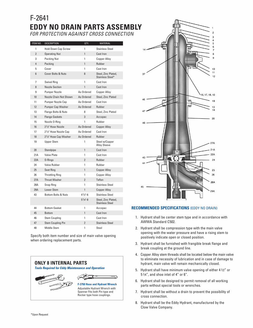
Specify both item number and size of main valve opening when ordering replacement parts.
Tools Required for Eddy Maintenance and OperationONLY 8 INTERNAL PARTS
F-2750 Hose and Hydrant WrenchAdjustable Hydrant Wrench with Spanner Fits both Pin type and Rocker type hose couplings.
RECOMMENDED SPECIFICATIONS (EDDY NO DRAIN)
1. Hydrant shall be center stem type and in accordance with AWWA Standard C502.
2. Hydrant shall be compression type with the main valve opening with the water pressure and have a rising stem to positively indicate open or closed position.
3. Hydrant shall be furnished with frangible break flange and break coupling at the ground line.
4. Copper Alloy stem threads shall be located below the main valve to eliminate necessity of lubrication and in case of damage to hydrant, main valve will remain mechanically closed.
5. Hydrant shall have minimum valve opening of either 4 1/2” or 5 1/4”, and shoe inlet of 4” or 6”.
6. Hydrant shall be designed to permit removal of all working parts without special tools or wrenches.
7. Hydrant shall be without a drain to prevent the possibility of cross connection.
8. Hydrant shall be the Eddy Hydrant, manufactured by the Clow Valve Company.
F-2641EDDY NO DRAIN PARTS ASSEMBLYFOR PROTECTION AGAINST CROSS CONNECTION
*Upon Request
1 Hold Down Cap Screw 1 Stainless Steel
2 Operating Nut 1 Cast Iron
3 Packing Nut 1 Copper Alloy
4 Packing 1 Rubber
5 Cover 1 Cast Iron
6 Cover Bolts & Nuts 8 Steel, Zinc Plated, Stainless Steel*
7 Swivel Ring 1 Cast Iron
8 Nozzle Section 1 Cast Iron
9 Pumper Nozzle As Ordered Copper Alloy
10 Nozzle Chain Not Shown As Ordered Steel, Zinc Plated
11 Pumper Nozzle Cap As Ordered Cast Iron
12 Pumper Cap Washer As Ordered Rubber
13 Flange Bolts & Nuts 8 Steel, Zinc Plated
14 Flange Gaskets 3 Accopac
15 Nozzle O-Ring 1 Rubber
16 21/2" Hose Nozzle As Ordered Copper Alloy
17 21/2" Hose Nozzle Cap As Ordered Cast Iron
18 21/2" Hose Cap Washer As Ordered Rubber
19 Upper Stem 1 Steel w/Copper Alloy Sleeve
20 Standpipe 1 Cast Iron
21A Valve Plate 1 Cast Iron
22A O-Rings 2 Rubber
24 Valve Rubber 1 Rubber
25 Seat Ring 1 Copper Alloy
26 Throttling Ring 1 Copper Alloy
27A Thrust Washer 2 Teflon
28A Snap Ring 1 Stainless Steel
29A Lower Stem 1 Copper Alloy
43 Bottom Bolts & Nuts 41/2"-6 Stainless Steel
51/4"-8 Steel, Zinc Plated, Stainless Steel
44 Bottom Gasket 1 Accopac
45 Bottom 1 Cast Iron
46 Stem Coupling 1 Cast Iron
47 Stem Coupling Pin 2 Stainless Steel
48 Middle Stem 1 Steel

PATRIOT HYDRANT CHECK VALVE
GUARD YOUR WATER SYSTEM FROM ACCIDENT OR ATTACK
ALUMINUM BRONZE CLAPPER WITH RESILIENT SEAT
Threats to the water supply can come from either accidental or deliberate acts. Our nation’s water superintendents have safeguarded nearly all of the access points to our drinking water. At this time one critical access point is left unprotected — the fire hydrant.
The Patriot hydrant check valve prevents reverse flow through the fire hydrant, safely protecting our drinking water while providing a full-port unobstructed waterway that allows firefighters access to the water they need when they need it.
Unlike locks and special external devices, the Patriot is installed underground, which prevents tampering and allows the hydrant to be operated the moment the firefighters arrive on the scene. The Patriot can be installed on any 6” mechanical joint connection, ensuring compatibility with all hydrant brands — providing the flexibility and cost-effectiveness you demand.

RECOMMENDED SPECIFICATIONSwww.clowvalve.com 1. The check valve shall be manufactured to all of the testing and performance
standards of AWWA C508 and AWWA C550. The Check Valve shall be designed for 250 PSI working pressure and tested to 500 PSI hydrostatic pressure.
2. The check valve shall be a stand alone unit able to be positively restrained to any 6” mechanical joint fire hydrant shoe.
3. The check valve shall be ductile iron ASTM Standard A536 (70-50-05), with NSF approved fusion bonded epoxy coating (interior/exterior).
4. The check valve shall be lead free, with no exposed lead bearing surfaces.
5. The check valve shall have an unobstructed waterway. No reduction of port or redirection of flow will be allowed.
6. The seat shall be retained via a double dove tail O-ring retaining groove design to ensure a positive seal.
7. The check valve shall incorporate integral positive restraint connections that maintain a restrained connection between the fire hydrant and the gate valve.
8. The check valve shall incorporate a stainless steel spring that hastens positive closure and prevents water hammer.
9. All fasteners shall be 304 stainless steel and all interior rubber components shall be EPDM rubber.
10. The check valve shall be produced with no less than 80% post consumer recycled content while being cast, manufactured, assembled and tested in the United States of America.
COMMITTED TO ENVIRONMENTAL RESPONSIBILITY
CLOW VALVE COMPANY IS COMMITTED TO PROTECTING OUR NATURAL RESOURCES THROUGH ENVIRONMENTALLY RESPONSIBLE
MANUFACTURING PRACTICES, INCLUDING THE USE OF 80+% RECYCLED CONTENT IN OUR HYDRANTS AND VALVES.
To learn more about our commitment to the environment, call 800-829-2569.
ISO 9001
902 South 2nd Street • Oskaloosa, Iowa 52577PHONE 641-673-8611 FAX 641-673-8269
Clow Valve is a division of McWane, Inc.
www.clowvalve.com
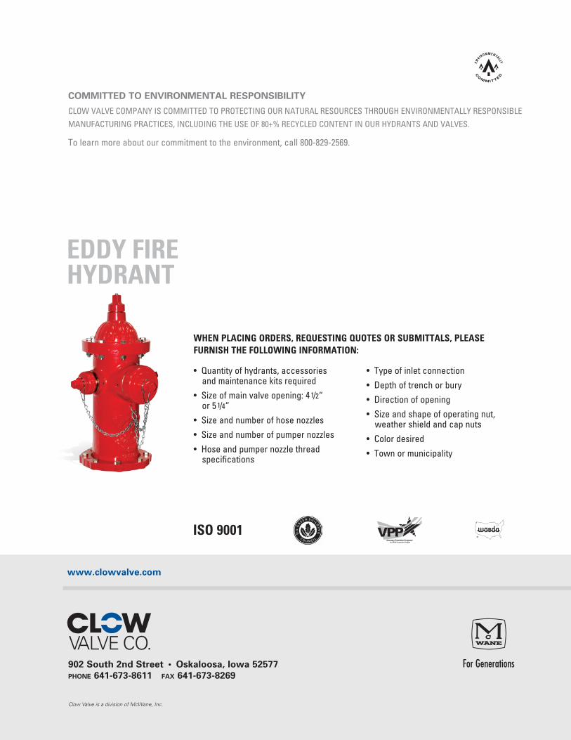
WHEN PLACING ORDERS, REQUESTING QUOTES OR SUBMITTALS, PLEASE FURNISH THE FOLLOWING INFORMATION:
EDDY FIRE HYDRANT
• Quantity of hydrants, accessories and maintenance kits required
• Size of main valve opening: 4 1/2“ or 5 1/4“
• Size and number of hose nozzles
• Size and number of pumper nozzles
• Hose and pumper nozzle thread specifications
• Type of inlet connection
• Depth of trench or bury
• Direction of opening
• Size and shape of operating nut, weather shield and cap nuts
• Color desired
• Town or municipality