
Eddy Current Inspection Conventional to Array 2017 A4A NDT ......Eddy current array • Eddy current...
50
Eddy Current Inspection Conventional to Array 2017 A4A NDT Forum Fort Lauderdale, September 2017 Presented by: Larry Culbertson
Transcript of Eddy Current Inspection Conventional to Array 2017 A4A NDT ......Eddy current array • Eddy current...
Eddy Current InspectionConventional to Array
2017 A4A NDT ForumFort Lauderdale, September 2017
Presented by: Larry Culbertson

• Eddy current testing (ECT) as a technique for testing finds its roots in electromagnetism. Eddy currents were first observed by François Arago in 1824, but French physicist Léon Foucault is credited with discovering them in 1855.
• Basic form — the single-element ECT probe — a coil of conductive wire is excited with an alternating electrical current. This wire coil produces an alternating magnetic field around itself. The magnetic field oscillates at the same frequency as the current running through the coil. When the coil approaches a conductive material, currents opposed to the ones in the coil are induced in the material — eddy currents.
• Eddy Current Arrays (ECA) have been evaluated since the late 70’s and 80’s as they were limited due to the computer capabilities.
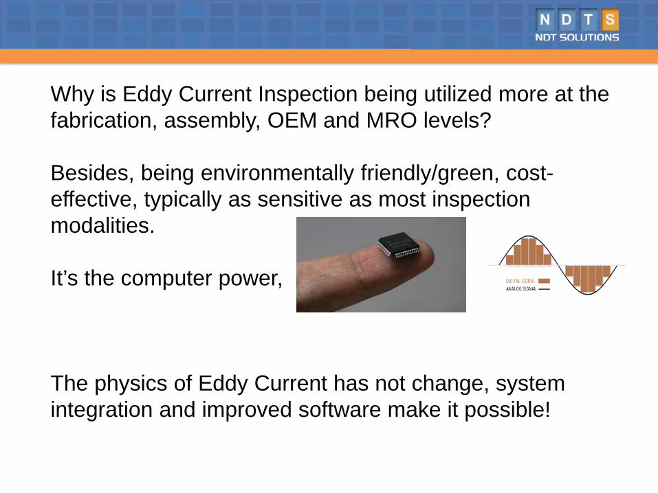
Why is Eddy Current Inspection being utilized more at the fabrication, assembly, OEM and MRO levels?
Besides, being environmentally friendly/green, cost-effective, typically as sensitive as most inspection modalities.
It’s the computer power,
The physics of Eddy Current has not change, system integration and improved software make it possible!
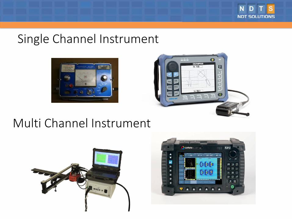
Single Channel Instrument
Multi Channel Instrument
ECT on surfaces• When it comes to surface applications, the performance of any given
inspection technique depends greatly on the specific conditions — mostly the types of materials and defects, but also surface conditions, etc.
• Effective on coatings/paint: yes• Computerized record keeping: partial• 3D/Advanced imaging: none• User dependence: high• Speed: low• Post-inspection analysis: none• Requires chemicals/consumables: no
Eddy current array• Eddy current array (ECA) and conventional ECT share the same basic
working principles. ECA technology provides the ability to electronically drive an array of coils ( multiple coils) arranged in specific pattern called a topology that generates a sensitivity profile suited to the target defects. Data acquisition is achieved by multiplexing the coils in a special pattern to avoid mutual inductance between the individual coils.
• Faster inspections• Wider coverage• Less operator dependence — array probes yield more consistent results
compared to manual raster scans• Better detection capabilities• Easier analysis because of simpler scan patterns• Improved positioning and sizing because of encoded data• Array probes can easily be designed to be flexible or shaped to
specifications, making hard-to-reach areas easier to inspect
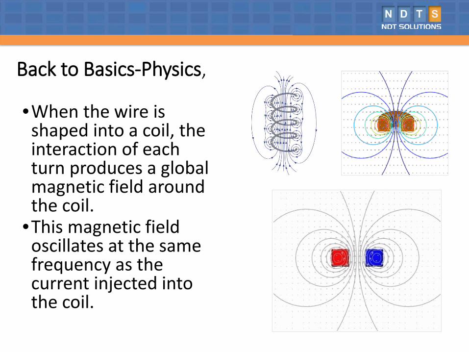
Back to Basics-Physics,
•When the wire is shaped into a coil, the interaction of each turn produces a global magnetic field around the coil.
•This magnetic field oscillates at the same frequency as the current injected into the coil.
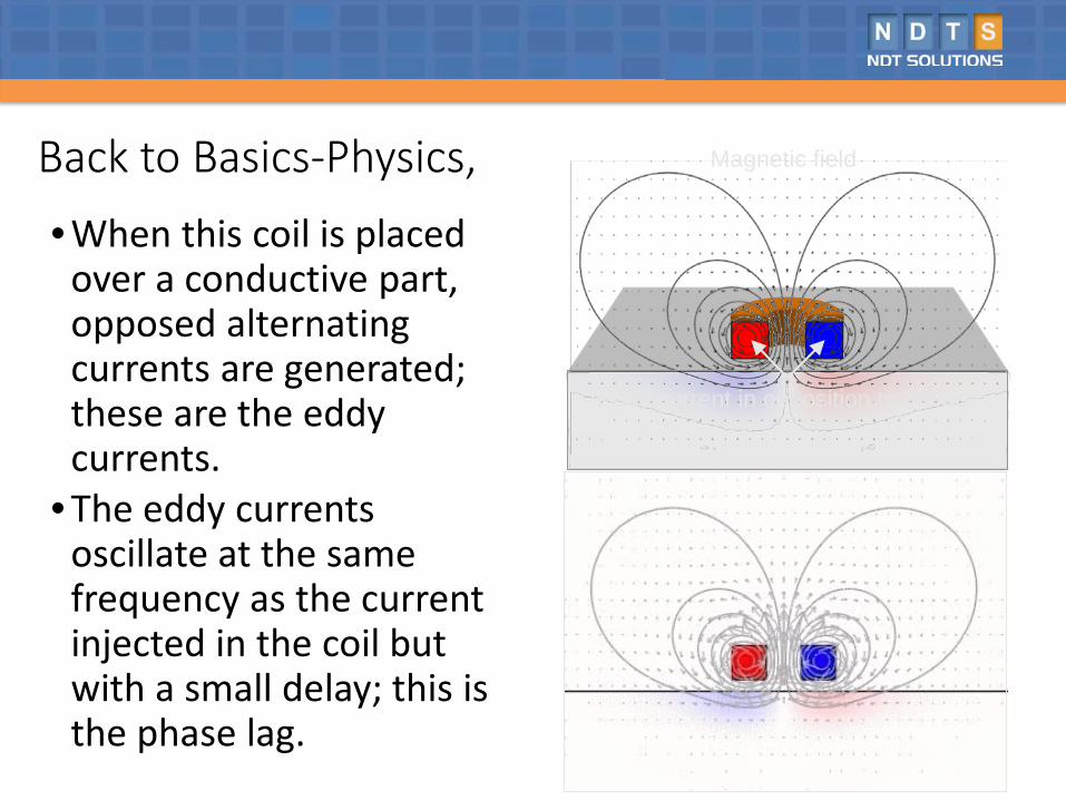
• When this coil is placed over a conductive part, opposed alternating currents are generated; these are the eddy currents.
• The eddy currents oscillate at the same frequency as the current injected in the coil but with a small delay; this is the phase lag.
Eddy current in opposition to the coil
Magnetic fieldBack to Basics-Physics,
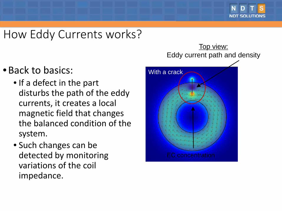
How Eddy Currents works?
• Back to basics: • If a defect in the part
disturbs the path of the eddy currents, it creates a local magnetic field that changes the balanced condition of the system.
• Such changes can be detected by monitoring variations of the coil impedance.
No defect
Top view:Eddy current path and density
With a crack
EC concentration
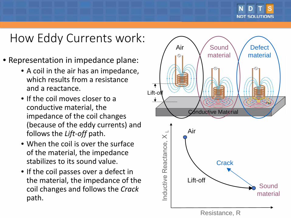
How Eddy Currents work:
• Representation in impedance plane:• A coil in the air has an impedance,
which results from a resistance and a reactance.
• If the coil moves closer to a conductive material, the impedance of the coil changes (because of the eddy currents) and follows the Lift-off path.
• When the coil is over the surface of the material, the impedance stabilizes to its sound value.
• If the coil passes over a defect in the material, the impedance of the coil changes and follows the Crackpath.
Resistance, R
Conductive Material
Crack
Lift-off
Air
Sound material
Lift-off
Air Soundmaterial
Defectmaterial
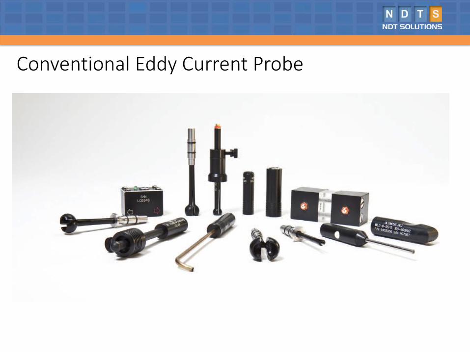
Conventional Eddy Current Probe
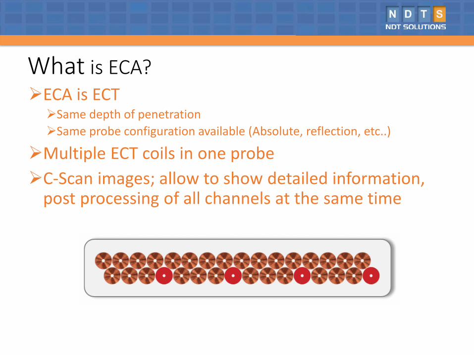
What is ECA?ECA is ECTSame depth of penetrationSame probe configuration available (Absolute, reflection, etc..)
Multiple ECT coils in one probeC-Scan images; allow to show detailed information,
post processing of all channels at the same time
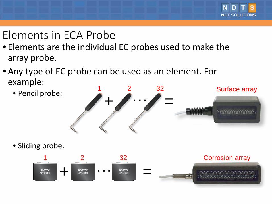
• Elements are the individual EC probes used to make the array probe.
• Any type of EC probe can be used as an element. For example:
• Pencil probe:
• Sliding probe:
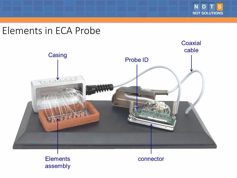
Elements in ECA Probe
…1 2 32
+ =Corrosion array
…1 2 32
+Surface array
=
Elements in ECA Probe
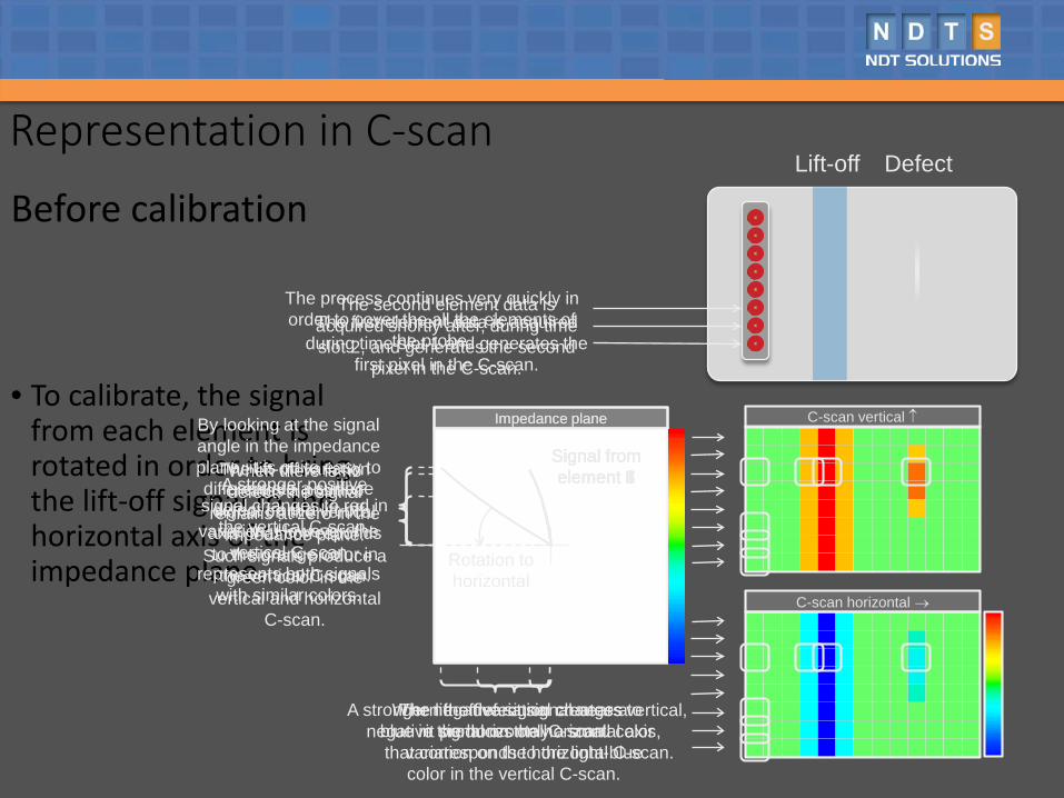
• To calibrate, the signal from each element is rotated in order to bring the lift-off signal to the horizontal axis of the impedance plane.
Representation in C-scan
Before calibration
Signal from element 6
Lift-off Defect
C-scan vertical ↑
C-scan horizontal →
Impedance plane
The lift-off variation creates a positive
signal on the vertical axis, that corresponds to the orange color in the vertical C-scan.
The lift-off variation creates a negative signal on the horizontal axis,
that corresponds to the light-blue color in the vertical C-scan.
A stronger positive signal changes to red in
the vertical C-scan.
A stronger negative signal changes to blue in the horizontal C-scan.
By looking at the signal angle in the impedance plane, it is quite easy to differentiate a surface defect from a lift-off
variation. However, the vertical C-scan
represents both signals with similar colors.
When the defect signal nears vertical, it produces only a small color
variation on the horizontal C-scan.
When there is no defect, the signal
remains at zero in the impedance plane.
Such signals produce a green color in the
vertical and horizontal C-scan.
The first element data is acquired during time slot 1 and generates the
first pixel in the C-scan.
The second element data is acquired shortly after, during time slot 2, and generates the second
pixel in the C-scan.
The process continues very quickly in order to cover the all the elements of
the probe.
Impedance plane
Signal from element 1
Signal from element 2
Signal from element 3
Signal from element 4
Signal from element 5
Signal from element 6
Signal from element 7
Signal from element 8
Rotation tohorizontal
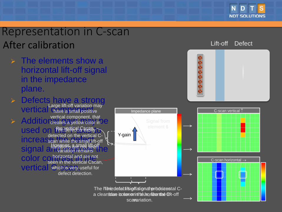
The elements show a horizontal lift-off signal in the impedance plane.
Defects have a strong vertical component.
Additional gain may be used on the Y-axis to increase the defect signal and improve the color contrast in the vertical C-scan.
Signal from element 6
Lift-off DefectRepresentation in C-scanAfter calibration
C-scan horizontal →
Impedance planeLarge lift-off variation may
have a small positive vertical component, that creates a yellow color in
the vertical Cscan.
However, a small lift-off variation remains
horizontal and are not seen in the vertical Cscan,
which is very useful for defect detection.
The horizontal lift-off signal produces a clear blue color on the horizontal C-
scan.
The defect is easily detected on the vertical C-scan while the small lift-off
variations are not seen.
The defect signal on the horizontal C-scan is seen in blue, like the lift-off
variation.
Impedance plane
Signal from element 1
Signal from element 6
Y-gain
C-scan vertical ↑
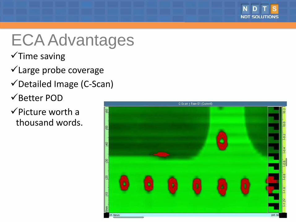
Time savingLarge probe coverageDetailed Image (C-Scan)Better PODPicture worth a
thousand words.
ECA Advantages
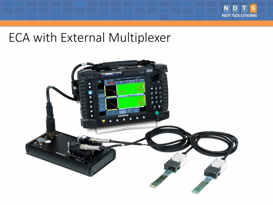
ECA with External Multiplexer
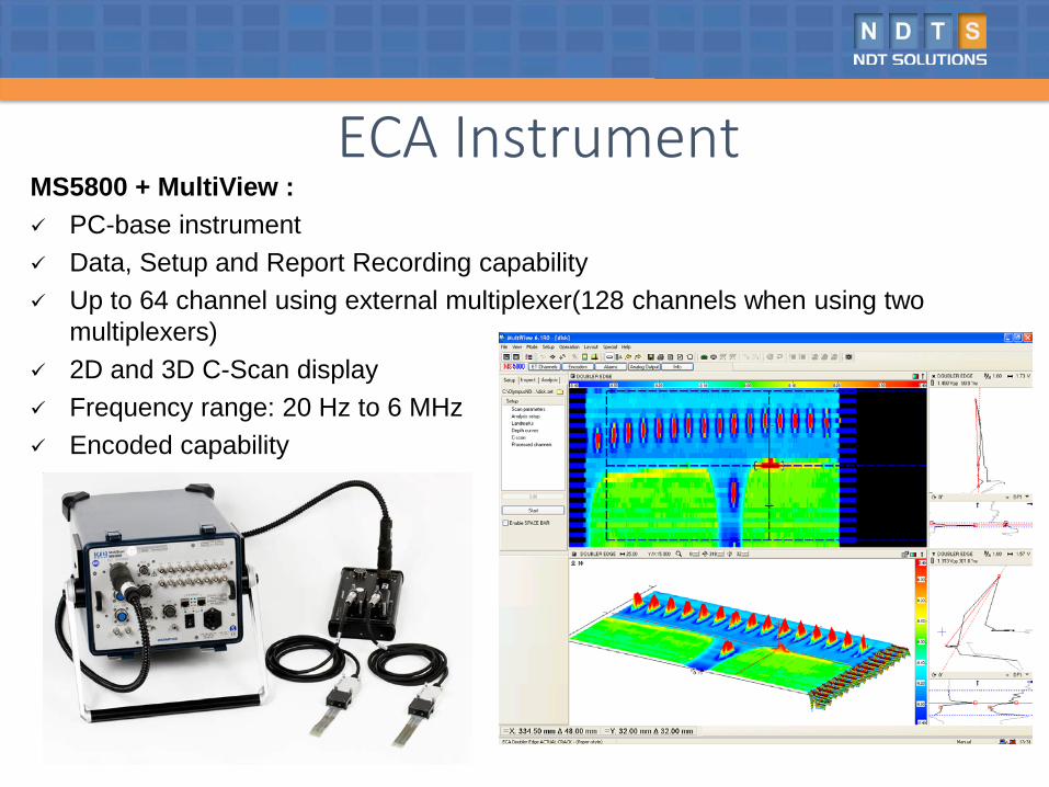
MS5800 + MultiView : PC-base instrument Data, Setup and Report Recording capability Up to 64 channel using external multiplexer(128 channels when using two
multiplexers) 2D and 3D C-Scan display Frequency range: 20 Hz to 6 MHz Encoded capability
ECA Instrument
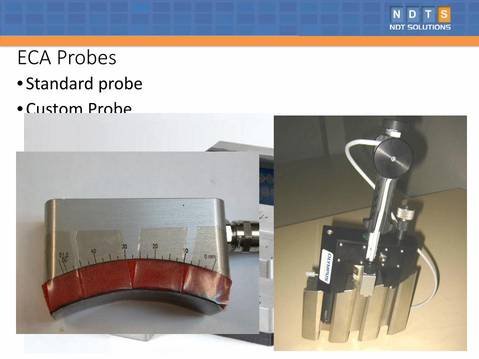
ECA Probes• Standard probe• Custom Probe
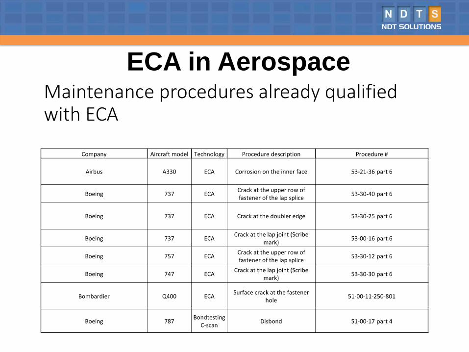
Maintenance procedures already qualified with ECA
ECA in Aerospace
Company Aircraft model Technology Procedure description Procedure #
Airbus A330 ECA Corrosion on the inner face 53-21-36 part 6
Boeing 737 ECA Crack at the upper row of fastener of the lap splice 53-30-40 part 6
Boeing 737 ECA Crack at the doubler edge 53-30-25 part 6
Boeing 737 ECA Crack at the lap joint (Scribe mark) 53-00-16 part 6
Boeing 757 ECA Crack at the upper row of fastener of the lap splice 53-30-12 part 6
Boeing 747 ECA Crack at the lap joint (Scribe mark) 53-30-30 part 6
Bombardier Q400 ECA Surface crack at the fastener hole 51-00-11-250-801
Boeing 787 Bondtesting C-scan Disbond 51-00-17 part 4
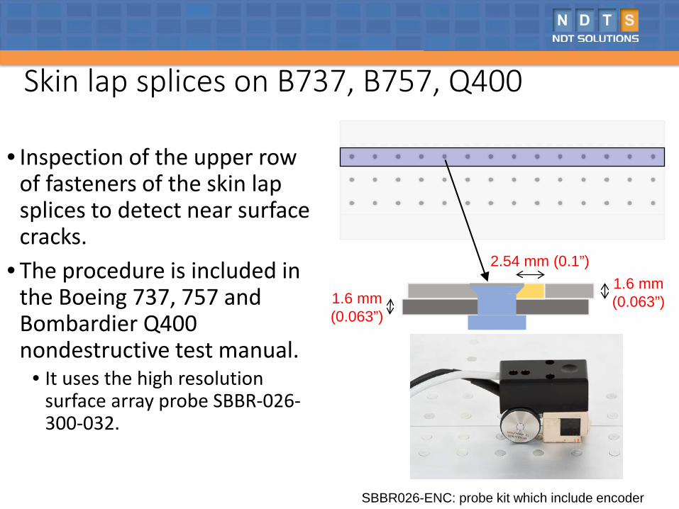
Skin lap splices on B737, B757, Q400
• Inspection of the upper row of fasteners of the skin lap splices to detect near surface cracks.
• The procedure is included in the Boeing 737, 757 and Bombardier Q400 nondestructive test manual.
• It uses the high resolution surface array probe SBBR-026-300-032.
1.6 mm(0.063”)1.6 mm
(0.063”)
2.54 mm (0.1”)
SBBR026-ENC: probe kit which include encoder
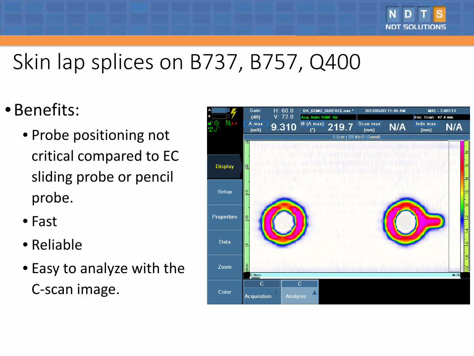
Skin lap splices on B737, B757, Q400
• Benefits:• Probe positioning not
critical compared to EC sliding probe or pencil probe.
• Fast• Reliable• Easy to analyze with the
C-scan image.
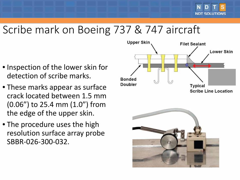
Scribe mark on Boeing 737 & 747 aircraft
• Inspection of the lower skin for detection of scribe marks.
• These marks appear as surface crack located between 1.5 mm (0.06”) to 25.4 mm (1.0”) from the edge of the upper skin.
• The procedure uses the high resolution surface array probe SBBR-026-300-032.
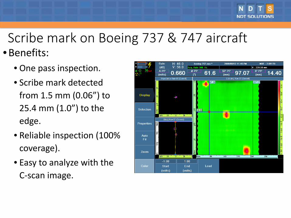
Scribe mark on Boeing 737 & 747 aircraft• Benefits:
• One pass inspection.• Scribe mark detected
from 1.5 mm (0.06”) to 25.4 mm (1.0”) to the edge.
• Reliable inspection (100% coverage).
• Easy to analyze with the C-scan image.
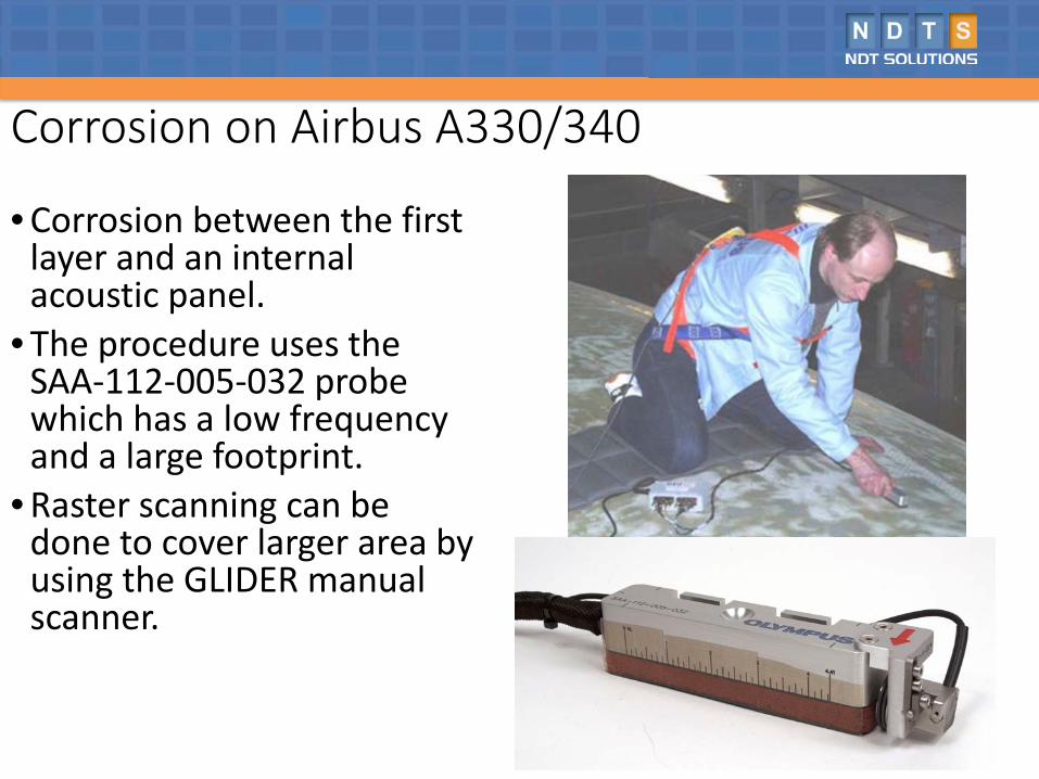
Corrosion on Airbus A330/340
• Corrosion between the first layer and an internal acoustic panel.
• The procedure uses the SAA-112-005-032 probe which has a low frequency and a large footprint.
• Raster scanning can be done to cover larger area by using the GLIDER manual scanner.
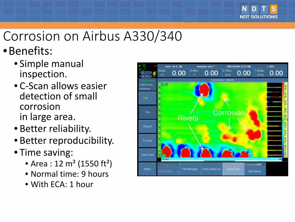
Corrosion on Airbus A330/340•Benefits:
• Simple manual inspection.
• C-Scan allows easier detection of small corrosionin large area.
• Better reliability.• Better reproducibility.• Time saving:
• Area : 12 m² (1550 ft²)• Normal time: 9 hours• With ECA: 1 hour
RivetsCorrosion
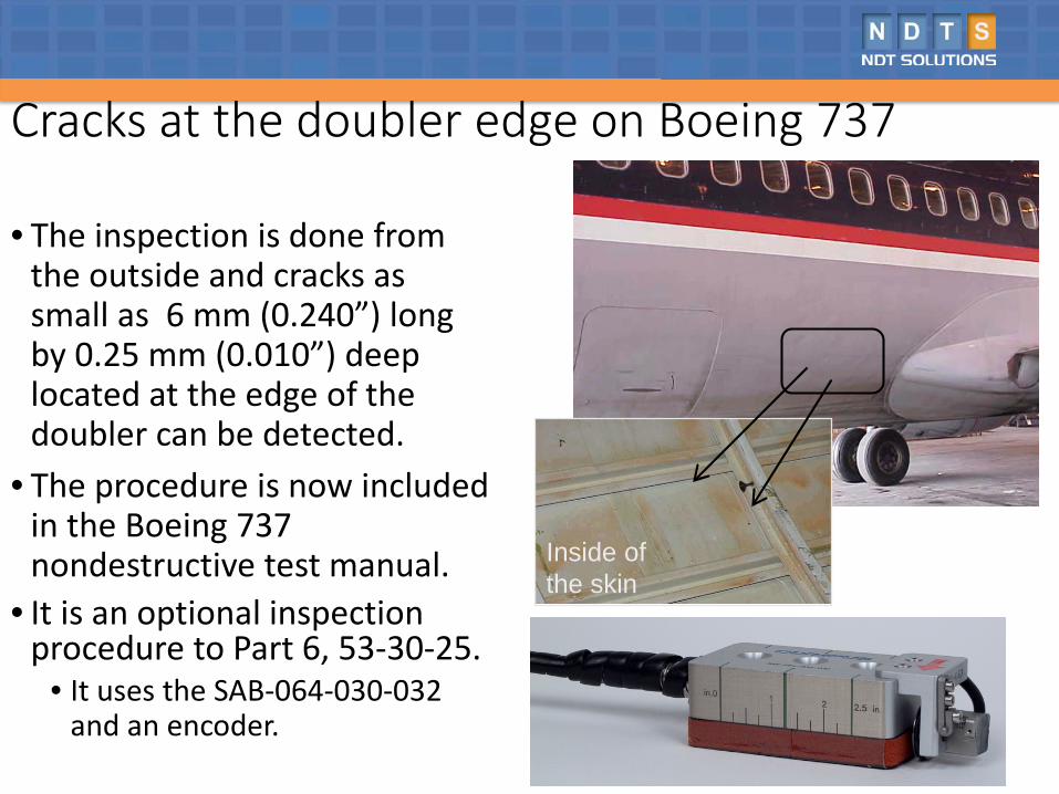
Cracks at the doubler edge on Boeing 737
• The inspection is done from the outside and cracks as small as 6 mm (0.240”) long by 0.25 mm (0.010”) deep located at the edge of the doubler can be detected.
• The procedure is now included in the Boeing 737 nondestructive test manual.
• It is an optional inspection procedure to Part 6, 53-30-25.
• It uses the SAB-064-030-032 and an encoder.
Inside of the skin
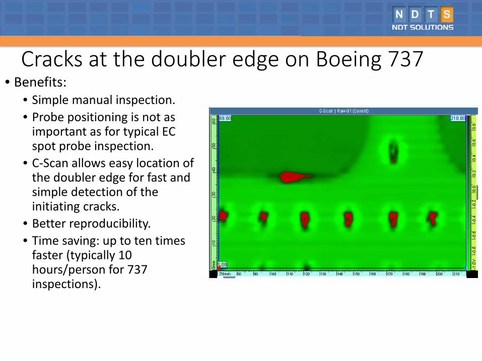
Cracks at the doubler edge on Boeing 737• Benefits:
• Simple manual inspection.• Probe positioning is not as
important as for typical EC spot probe inspection.
• C-Scan allows easy location of the doubler edge for fast and simple detection of the initiating cracks.
• Better reproducibility.• Time saving: up to ten times
faster (typically 10 hours/person for 737 inspections).
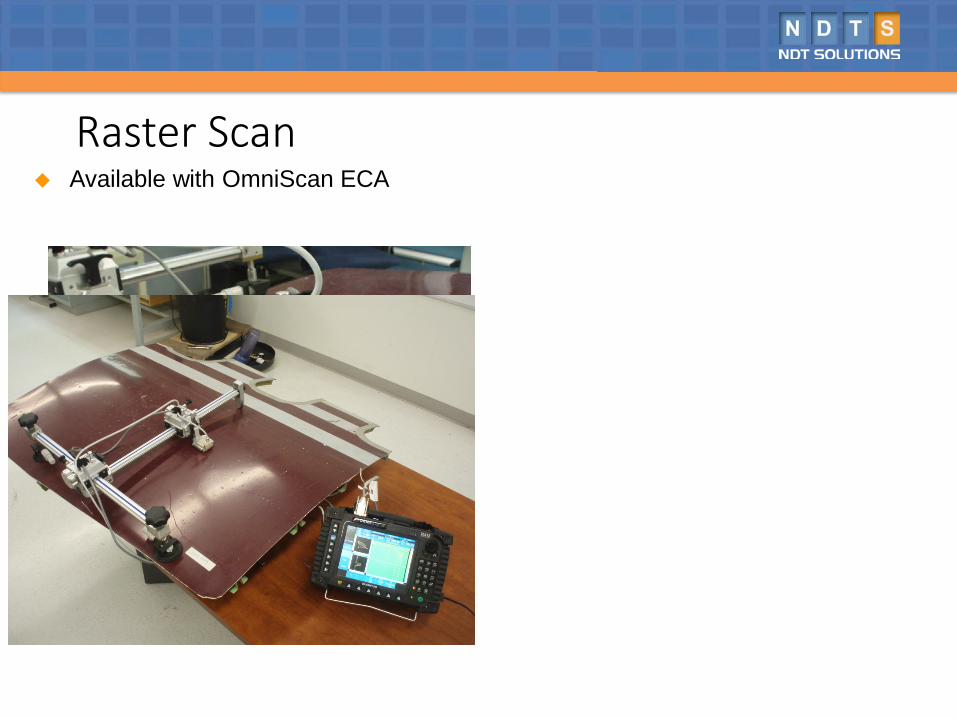
Raster Scan Available with OmniScan ECA
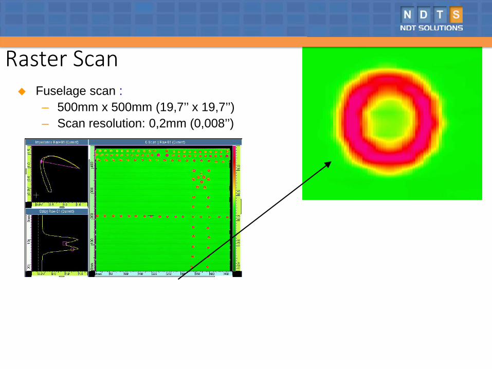
Raster Scan Fuselage scan :
– 500mm x 500mm (19,7’’ x 19,7’’)– Scan resolution: 0,2mm (0,008’’)
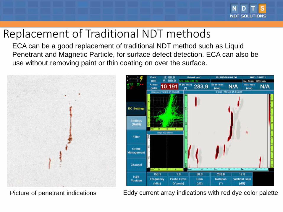
Replacement of Traditional NDT methodsECA can be a good replacement of traditional NDT method such as Liquid Penetrant and Magnetic Particle, for surface defect detection. ECA can also be use without removing paint or thin coating on over the surface.
Picture of penetrant indications Eddy current array indications with red dye color palette
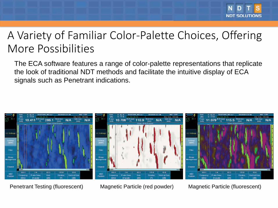
A Variety of Familiar Color-Palette Choices, Offering More Possibilities
The ECA software features a range of color-palette representations that replicate the look of traditional NDT methods and facilitate the intuitive display of ECA signals such as Penetrant indications.
Penetrant Testing (fluorescent) Magnetic Particle (red powder) Magnetic Particle (fluorescent)
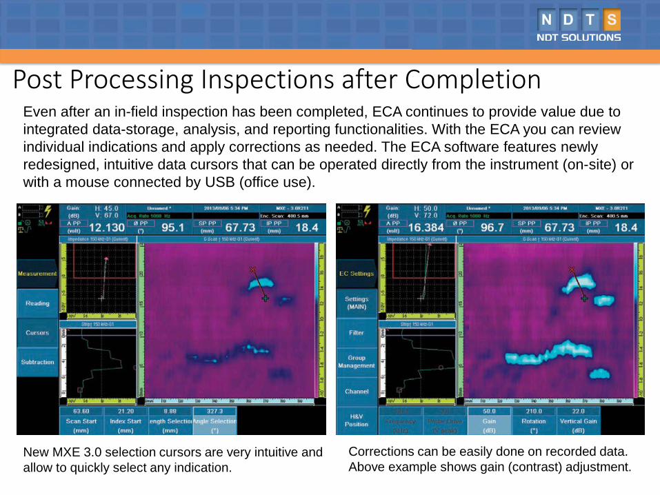
Post Processing Inspections after CompletionEven after an in-field inspection has been completed, ECA continues to provide value due to integrated data-storage, analysis, and reporting functionalities. With the ECA you can review individual indications and apply corrections as needed. The ECA software features newly redesigned, intuitive data cursors that can be operated directly from the instrument (on-site) or with a mouse connected by USB (office use).
New MXE 3.0 selection cursors are very intuitive and allow to quickly select any indication.
Corrections can be easily done on recorded data. Above example shows gain (contrast) adjustment.
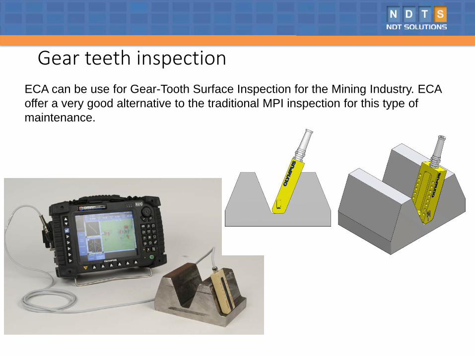
Gear teeth inspectionECA can be use for Gear-Tooth Surface Inspection for the Mining Industry. ECA offer a very good alternative to the traditional MPI inspection for this type of maintenance.
Probe Resolution
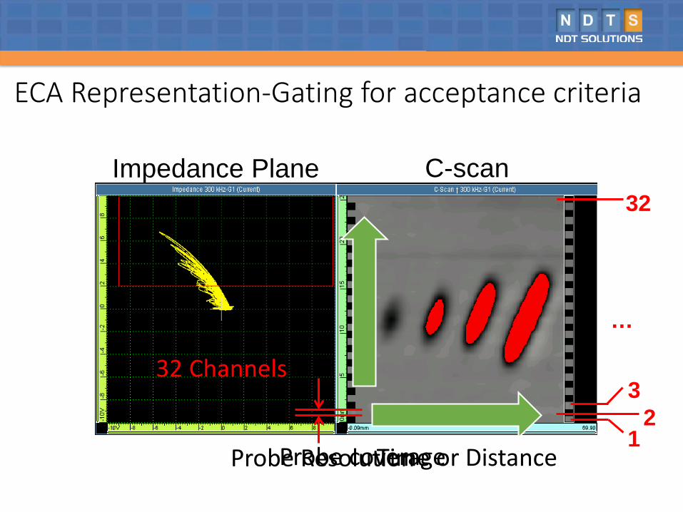
ECA Representation-Gating for acceptance criteria
Impedance Plane
32 Channels
C-scan
Time or Distance
…
32
21
3
Probe coverage
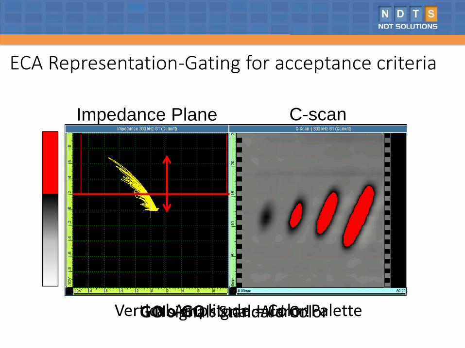
Impedance Plane C-scan
Vertical Amplitude = Color PaletteGO signal: Standard ColorNo-GO signal: Alarm!
ECA Representation-Gating for acceptance criteria
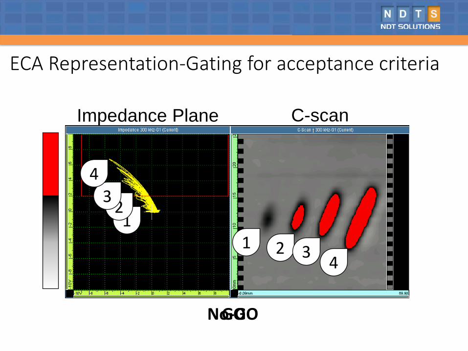
Impedance Plane C-scan
11
GONo-GO
2
2
3
3
4
4
ECA Representation-Gating for acceptance criteria
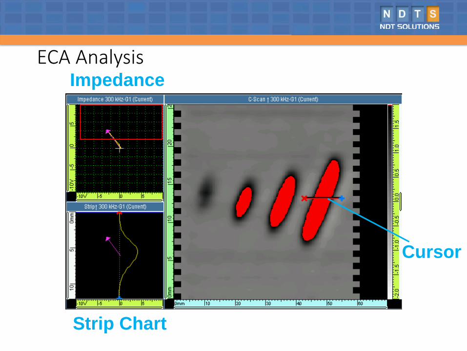
ECA Analysis
Cursor
Impedance
Strip Chart
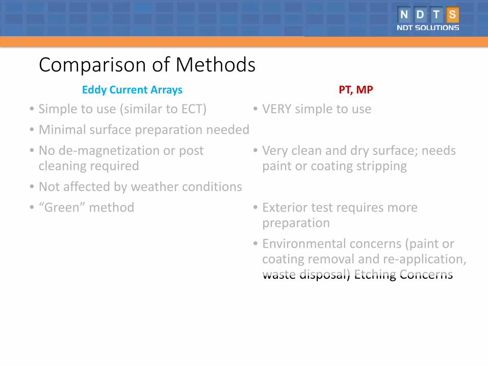
Comparison of MethodsEddy Current Arrays
• Simple to use (similar to ECT)• Minimal surface preparation needed• No de-magnetization or post
cleaning required• Not affected by weather conditions• “Green” method
PT, MP
• VERY simple to use
• Very clean and dry surface; needs paint or coating stripping
• Exterior test requires more preparation
• Environmental concerns (paint or coating removal and re-application, waste disposal) Etching Concerns
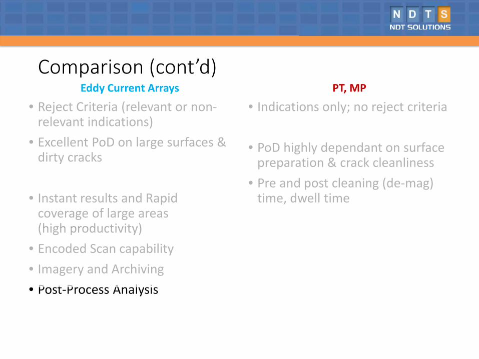
Comparison (cont’d)Eddy Current Arrays
• Reject Criteria (relevant or non-relevant indications)
• Excellent PoD on large surfaces & dirty cracks
• Instant results and Rapid coverage of large areas(high productivity)
• Encoded Scan capability• Imagery and Archiving• Post-Process Analysis
PT, MP
• Indications only; no reject criteria
• PoD highly dependant on surface preparation & crack cleanliness
• Pre and post cleaning (de-mag) time, dwell time
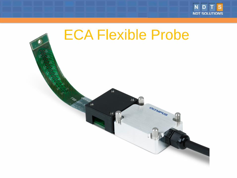
ECA Flexible Probe
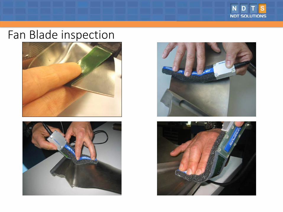
Fan Blade inspection
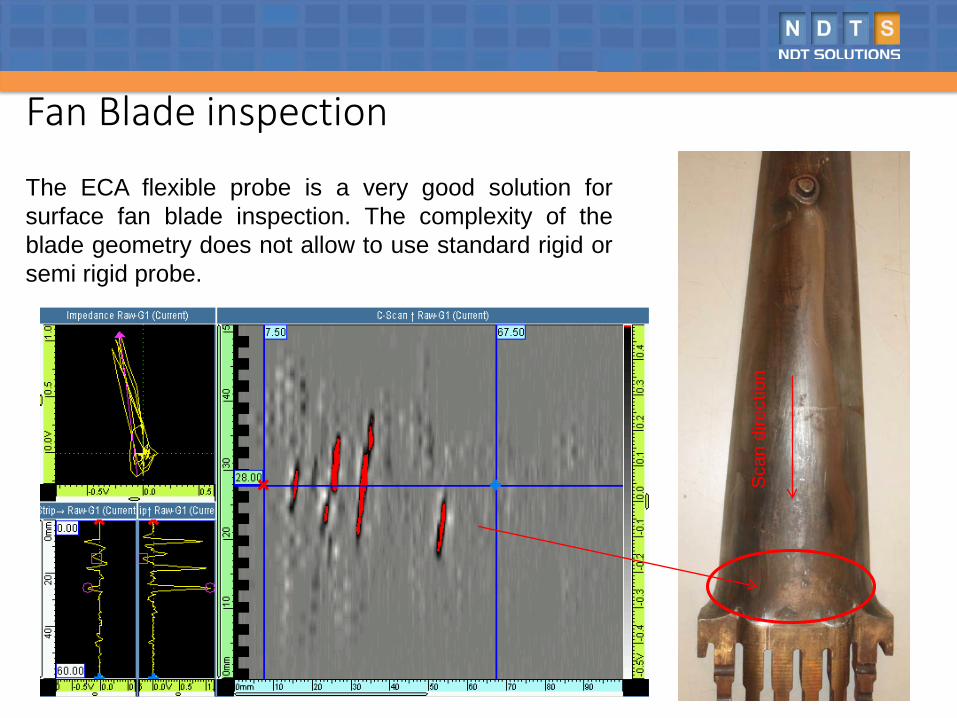
Fan Blade inspection
The ECA flexible probe is a very good solution forsurface fan blade inspection. The complexity of theblade geometry does not allow to use standard rigid orsemi rigid probe.
Scan
dire
ctio
n
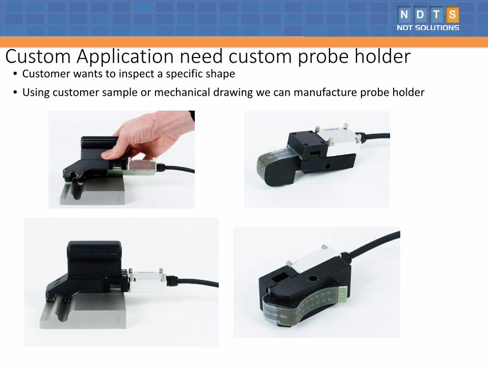
Custom Application need custom probe holder• Customer wants to inspect a specific shape• Using customer sample or mechanical drawing we can manufacture probe holder
Conclusion:Eddy current array (ECA) share the same basic working principles. ECA technology provides the ability to electronically drive an array of multiple coils arranged in specific pattern called a topology that generates a sensitivity profile suited to the target defects. Data acquisition is achieved by multiplexing the coils in a special pattern to avoid mutual inductance between the individual coils.
This will improve the inspection! Faster inspections Wider (more area) coverage Less operator dependence — array probes yield more consistent results
compared to manual raster scans Improved detection capabilities Easier analysis because of simpler scan patterns Improved positioning and sizing because of encoded data Array probes can easily be designed to be flexible or shaped to specifications,
making hard-to-reach areas easier to inspect
Acknowledgements:
Tommy Bourgelas, Product Manager, Eddy Current Product LineWayne Wiesner, Director, Vertical Market - Military Aircraft /
Airframes Business Development ManagerDusty Moore, Systems & Integration Sales Manager – Americas

Thank you!


![Application of Eddy Current Array Technology from …2 EC array technology (ECA) started in the 1990s [1],[2] resulting in the first commercially available EC-arrays in the early years](https://static.fdocuments.in/doc/165x107/5e69371755cab27b5b512dfb/application-of-eddy-current-array-technology-from-2-ec-array-technology-eca-started.jpg)