Bandwidth Allocation in Networks with Multiple Interferences

ECUC Deliverable D2.4-4 Due date: 28th February 2013
FP7 TRANSPORT Contract No. 314244 1 September 2012 - 31 August 2015 Page 1 of 21
DELIVERABLE D2.4 - 4
Qualitative relationship between requirements and design parameters
Contract number : 314244
Project acronym : ECUC
Project title : EDDY CURRENT BRAKE COMPATIBILITY
Deliverable number : D2.4
Nature :
Dissemination level : PU (Public) draft
Report date : 28 February 2013
Author(s): Aurich, Stefan; Lehmann, Henry
Partners contributed : CEIT, KB, ALSTOM, SNCF, DB
Contact : Dr.-Ing. Henry Lehmann, Knorr-Bremse GmbH, Beethovengasse 43 – 45, A-2340 Mödling +43 2236 409 2383, [email protected] Stefan Aurich, Knorr-Bremse SfS GmbH, Moosacher Str. 80, D-80809 München +49 89 3547 2174, [email protected]
ECUC Eddy CUrrent brake Compatibility
The ECUC project was funded by the European Commission under the 7th Framework Programme (FP7) –Transport
Coordinator: CEIT
ECUC Deliverable D2.4-4 Due date: 28th February 2013
FP7 TRANSPORT Contract No. 314244 1 September 2012 - 31 August 2015 Page 2 of 21
TABLE OF CONTENTS List of Figures ................................................................................................................................. 3
List of Tables ................................................................................................................................... 3
Table of versions ............................................................................................................................. 4
1. Introduction ................................................................................................................................. 5
2. Description .................................................................................................................................. 5
3. Infrastructure ............................................................................................................................... 5
3.1 Track ..................................................................................................................................... 5
3.2 Signalling systems ................................................................................................................ 6
3.3 Rolling Stock ......................................................................................................................... 7
3.3.1 Brake performance .................................................................................................... 7
3.3.2 Brake performance in ETCS operation ..................................................................... 9
3.3.3 Thermal limits .......................................................................................................... 10
3.3.4 Adhesion ................................................................................................................. 15
3.3.5 Brake forces ............................................................................................................ 16
3.4 Operation ............................................................................................................................ 18
3.4.1 Station spacing ........................................................................................................ 18
3.4.2 Deceleration in case of service brake application ................................................... 18
4. IMPACT TO DESIGN OF ECB ................................................................................................. 18
4.1 Number Of ECB Equipped Bogies Per Train ...................................................................... 18
4.2 Brake Performance ............................................................................................................. 19
4.2.1 Mechanical characteristics of ECB .......................................................................... 20
4.2.2 Dependence of Brake cycle on temperature ........................................................... 20
4.3 Air Gap ................................................................................................................................ 21
4.4 Force And Pressure Control ............................................................................................... 21
4.5 Power Consumption ............................................................................................................ 21

ECUC Deliverable D2.4-4 Due date: 28th February 2013
FP7 TRANSPORT Contract No. 314244 1 September 2012 - 31 August 2015 Page 3 of 21
LIST OF FIGURES Figure 1: effects of electromagnetic interferences .......................................................................... 7
Figure 2: Disc temperature for a wheel mounted disc on the motor axle of the prototype vehicle, gradient 35 ‰, initial speed 320 km/h, friction brake and ECB, “20-1” ................................. 11
Figure 3: Disc temperature for an axle mounted disc on the trailer axle of the prototype vehicle, gradient 35 ‰, initial speed 320 km/h, friction brake and ECB, “20-2” ................................. 12
Figure 4: Disc temperature for a wheel mounted disc on the motor axle of the prototype vehicle, gradient 35 ‰, initial speed 320 km/h, friction brake only, “24-1” ......................................... 12
Figure 5: Disc temperature for an axle mounted disc on the trailer axle of the prototype vehicle, gradient 35 ‰, initial speed 320 km/h, friction brake only, “24-2” ......................................... 13
Figure 6: Thermal simulation of ECB ............................................................................................ 15
Figure 7: Brake force distribution for 2/3 service brake application with ECB .............................. 17
Figure 8: Brake force distribution for 2/3 service brake application without ECB ......................... 17
Figure 9: examples of train configuration ...................................................................................... 19
Figure 10: Characteristic curve of brake force and attraction force .............................................. 20
LIST OF TABLES Table 1: Deceleration requirements of TSI HS RST, § 4.2.4.1 ....................................................... 8
Table 2: Stopping distance requirements of TSI HS RST, § 4.2.4.1 ............................................... 8
Table 3: Calculated stopping distances in Mode R and R+ECB, prototype vehicle ........................ 9
Table 4: Disc temperatures during emergency brake application in a 35 ‰ gradient at initial speed, maximum exceptional load, in brake configuration R and R+ECB. AMD: Axle mounted disc on trailer car; WMD: wheel mounted disc on motor car .................................. 13
Table 5: speed restrictions on gradients according to French homologation document SAM F 018 .............................................................................................................................................. 14
Table 6: Allocation of brake forces ................................................................................................ 16
Table 7: requirements of brake force depend of number of equipped ECB .................................. 19
ECUC Deliverable D2.4-4 Due date: 28th February 2013
FP7 TRANSPORT Contract No. 314244 1 September 2012 - 31 August 2015 Page 4 of 21
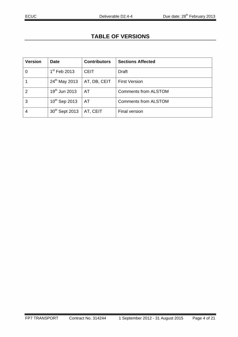
TABLE OF VERSIONS
Version Date Contributors Sections Affected
0 1st Feb 2013 CEIT Draft
1 24th May 2013 AT, DB, CEIT First Version
2 19th Jun 2013 AT Comments from ALSTOM
3 10th Sep 2013 AT Comments from ALSTOM
4 30th Sept 2013 AT, CEIT Final version
ECUC Deliverable D2.4-4 Due date: 28th February 2013
FP7 TRANSPORT Contract No. 314244 1 September 2012 - 31 August 2015 Page 5 of 21
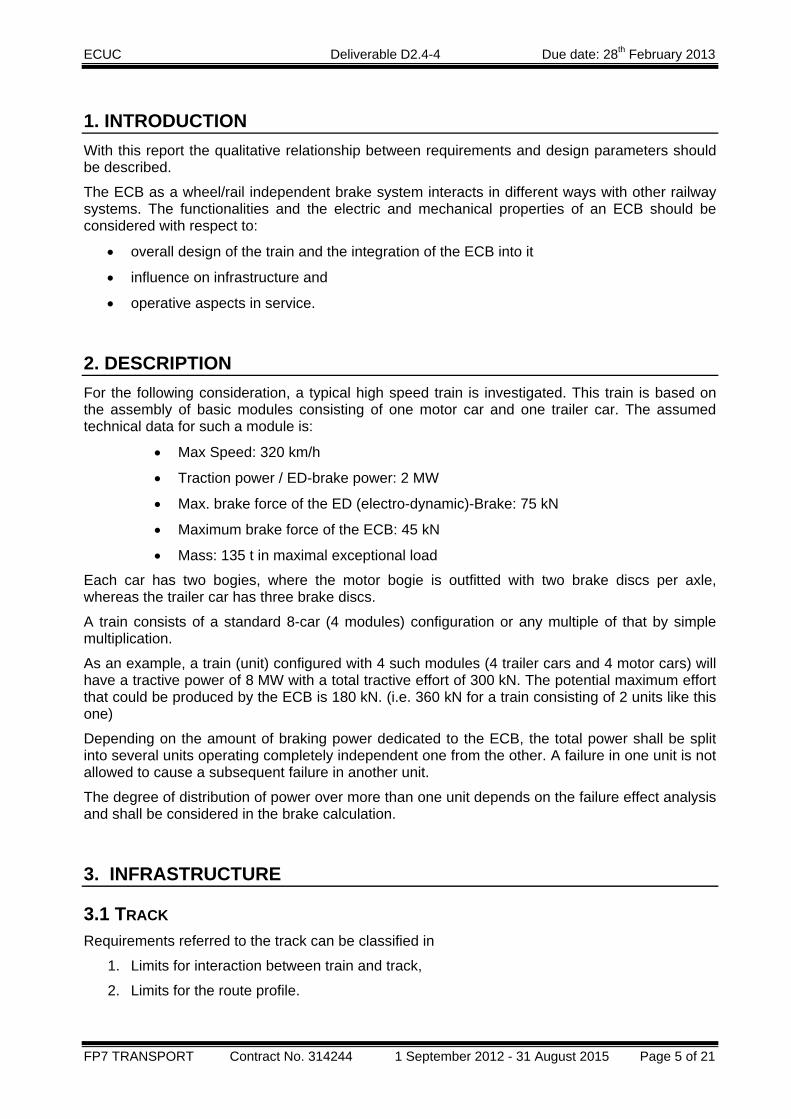
1. INTRODUCTION With this report the qualitative relationship between requirements and design parameters should be described.
The ECB as a wheel/rail independent brake system interacts in different ways with other railway systems. The functionalities and the electric and mechanical properties of an ECB should be considered with respect to:
• overall design of the train and the integration of the ECB into it
• influence on infrastructure and
• operative aspects in service.
2. DESCRIPTION For the following consideration, a typical high speed train is investigated. This train is based on the assembly of basic modules consisting of one motor car and one trailer car. The assumed technical data for such a module is:
• Max Speed: 320 km/h
• Traction power / ED-brake power: 2 MW
• Max. brake force of the ED (electro-dynamic)-Brake: 75 kN
• Maximum brake force of the ECB: 45 kN
• Mass: 135 t in maximal exceptional load
Each car has two bogies, where the motor bogie is outfitted with two brake discs per axle, whereas the trailer car has three brake discs.
A train consists of a standard 8-car (4 modules) configuration or any multiple of that by simple multiplication.
As an example, a train (unit) configured with 4 such modules (4 trailer cars and 4 motor cars) will have a tractive power of 8 MW with a total tractive effort of 300 kN. The potential maximum effort that could be produced by the ECB is 180 kN. (i.e. 360 kN for a train consisting of 2 units like this one)
Depending on the amount of braking power dedicated to the ECB, the total power shall be split into several units operating completely independent one from the other. A failure in one unit is not allowed to cause a subsequent failure in another unit.
The degree of distribution of power over more than one unit depends on the failure effect analysis and shall be considered in the brake calculation.
3. INFRASTRUCTURE
3.1 TRACK Requirements referred to the track can be classified in
1. Limits for interaction between train and track,
2. Limits for the route profile.

ECUC Deliverable D2.4-4 Due date: 28th February 2013
FP7 TRANSPORT Contract No. 314244 1 September 2012 - 31 August 2015 Page 6 of 21
3.1.1 Limits for interaction train / track TSI HS RST defines the maximum impact of a train on the track as follows:
The maximum deceleration of a train must not exceed 2.5 m/s² (TSI HS RST, § 4.2.4.5 and § 4.2.3.4.3).
The brake force of the ECB that may be executed on the track is limited depending on the brake mode, § 4.2.4.5:
‐ 360 kN during emergency braking
‐ 180 kN for maximum service brak105 kN for 2/3 of maximum service brake.
The permission to use the ECB for an emergency and/or service brake application must be stated in the Infrastructure Register. Note that the current TSI INF requires that the ECB should be allowed in emergency brake everywhere, whereas for service brake its use is only allowed on the listed lines in the infrastructure register.
The TSI does not define a distinction between different types of tracks, for instance there is no distinction between “ballasted tracks” and “non-ballasted tracks”
The TSI HS RST defines the maximum impacts of the ECB of a train on the track. The necessary brake performance of the ECB is dependent on the speed, the mass and the brake equipment of a train, the operation cycle and the approval for emergency and/or service brake application.
3.1.2 Limits for the route profile According to TSI Infrastructure (TSI INF § 4.2.5) the maximum gradient of class 1 routes is defined as follows:
‐ 35 ‰ over a maximum length of 6.000 m
‐ 25 ‰ maximum inclination of the sliding mean average over a length of 10.000 m.
3.2 SIGNALLING SYSTEMS The requirements listed in TSI CR CCS and TSI HS RST do not give any specific defaults of design of ECB. The ECB is located in the sensitive zone of axle counters.
The interferences between ECB and signalling systems may be split into 3 groups.
The passive interaction is comparable with the situation which is described in EN50238 figure A.22. The ECB is de-energized. The electromagnetic fields emitted from the active signalling devices interfere with the metal body and coils of ECB.
The active low frequency interaction is a result of the strong magnetic field generated by the ECB. This primary magnetic field generated by the ECB is a static magnetic field. The movement of the magnetic field - relative to the signalling device or the rail – produces an alternating magnetic field. The base frequency of this magnetic field depends on the speed of movement and the pole pitch of ECB, see D2.3 clause 3.1. Due to the non-linear magnetic characteristics of the materials, the harmonics of the base frequency must also be considered. This effect can also be caused by the variations of the magnetic coupling between the magnetic arrangement and the rail due to vertical oscillations of the mechanical structure.
The third type is active mean and high frequency interactions which are mainly caused by the electric power supply of the ECB.

ECUC Deliverable D2.4-4 Due date: 28th February 2013
FP7 TRANSPORT Contract No. 314244 1 September 2012 - 31 August 2015 Page 7 of 21
Figure 1: Effects of electromagnetic interferences The compatibility of the train/ECB and the signaling system has to be verified during running tests. An overview of signaling systems and types of signaling devices in use are listed in the standards EN50238, CLC-TS50238-2 and CLC-TS50238-3.
The compatibility of the train/ECB and the signaling system has to be verified during running tests. The compatibility requirements between the train and signaling systems have been defined in section 4 of D2.2 of this project.
3.3 ROLLING STOCK
3.3.1 Brake performance The brake performance of high speed trains is defined on a European level in the TSI HS RST. In addition, national requirements still exist, which are not further discussed in this context.
According to TSI HS RST, § 4.2.4.1, the following requirements apply:
ECUC Deliverable D2.4-4 Due date: 28th February 2013
FP7 TRANSPORT Contract No. 314244 1 September 2012 - 31 August 2015 Page 8 of 21
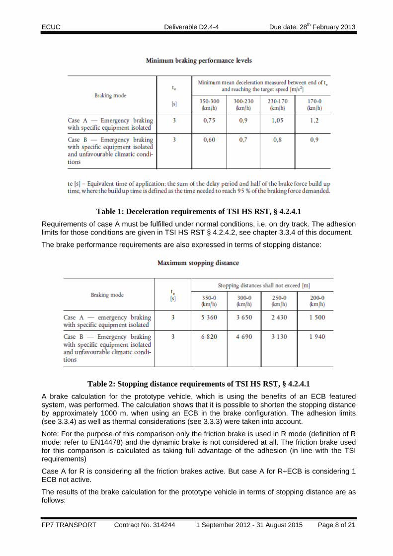
Table 1: Deceleration requirements of TSI HS RST, § 4.2.4.1
Requirements of case A must be fulfilled under normal conditions, i.e. on dry track. The adhesion limits for those conditions are given in TSI HS RST § 4.2.4.2, see chapter 3.3.4 of this document.
The brake performance requirements are also expressed in terms of stopping distance:
Table 2: Stopping distance requirements of TSI HS RST, § 4.2.4.1
A brake calculation for the prototype vehicle, which is using the benefits of an ECB featured system, was performed. The calculation shows that it is possible to shorten the stopping distance by approximately 1000 m, when using an ECB in the brake configuration. The adhesion limits (see 3.3.4) as well as thermal considerations (see 3.3.3) were taken into account.
Note: For the purpose of this comparison only the friction brake is used in R mode (definition of R mode: refer to EN14478) and the dynamic brake is not considered at all. The friction brake used for this comparison is calculated as taking full advantage of the adhesion (in line with the TSI requirements)
Case A for R is considering all the friction brakes active. But case A for R+ECB is considering 1 ECB not active.
The results of the brake calculation for the prototype vehicle in terms of stopping distance are as follows:

ECUC Deliverable D2.4-4 Due date: 28th February 2013
FP7 TRANSPORT Contract No. 314244 1 September 2012 - 31 August 2015 Page 9 of 21
Initial speed
300 km/h 320 km/h
Brake configuration Stopping distance [m]
R+ECB 3088 3504
R+(ECB-1) (case A) 3278 3718
R 4046 4578
Table 3: Calculated stopping distances in Mode R and R+ECB, prototype vehicle
The calculation was performed with the following brake force characteristic of the ECB
F_WB
Speed [km/h]340320300280260240220200180160140120100806040200
Forc
e [k
N]
45,0
40,0
35,0
30,0
25,0
20,0
15,0
10,0
5,0
0,0
Figure 2: ECB Brake force characteristic for 1 car, i.e. 2 bogies Figure 2 shows the brake force characteristic of 1 car outfitted with the ECB in 2 bogies.
3.3.2 Brake performance in ETCS operation In ETCS operation not only the nominal performance is to be considered but most important is the guaranteed (safe) performance (see ETCS System Requirements Specification for more detailed information). A better guaranteed performance in ETCS field enables a train to be instructed to brake later compared to a more traditional train. Therefore the average speed and the route capacity can be improved.
In this field the ECB technology provides a decisive advantage as it is fully independent from any adhesion issues.
The accuracy and reliability of the overall performance of the ECB system (ECB plus its control system) has to be further analysed to demonstrate the overall advantage vs. traditional brake system. This analysis shall be part of the current ECUC project.
ECUC Deliverable D2.4-4 Due date: 28th February 2013
FP7 TRANSPORT Contract No. 314244 1 September 2012 - 31 August 2015 Page 10 of 21
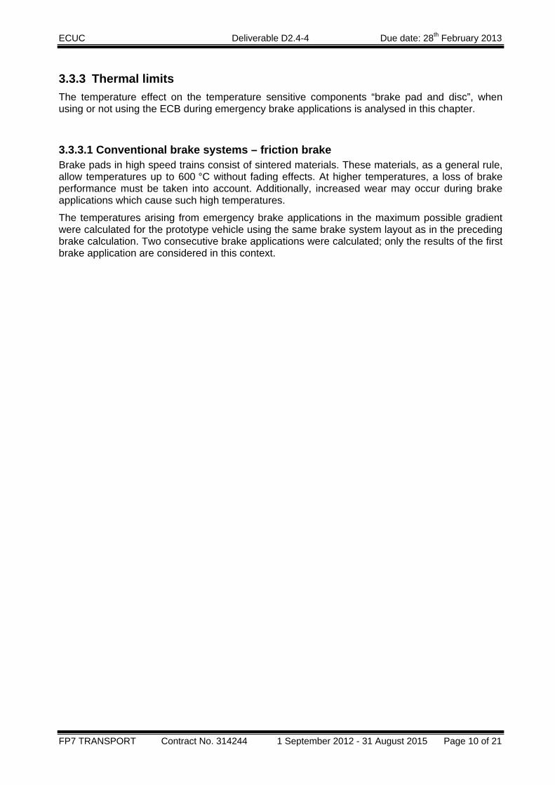
3.3.3 Thermal limits The temperature effect on the temperature sensitive components “brake pad and disc”, when using or not using the ECB during emergency brake applications is analysed in this chapter.
3.3.3.1 Conventional brake systems – friction brake Brake pads in high speed trains consist of sintered materials. These materials, as a general rule, allow temperatures up to 600 °C without fading effects. At higher temperatures, a loss of brake performance must be taken into account. Additionally, increased wear may occur during brake applications which cause such high temperatures.
The temperatures arising from emergency brake applications in the maximum possible gradient were calculated for the prototype vehicle using the same brake system layout as in the preceding brake calculation. Two consecutive brake applications were calculated; only the results of the first brake application are considered in this context.
ECUC Deliverable D2.4-4 Due date: 28th February 2013
FP7 TRANSPORT Contract No. 314244 1 September 2012 - 31 August 2015 Page 11 of 21
Figure 3: Disc temperature for a wheel mounted disc on the motor axle of the prototype
vehicle, gradient 35 ‰, initial speed 320 km/h, friction brake and ECB,
ECUC Deliverable D2.4-4 Due date: 28th February 2013
FP7 TRANSPORT Contract No. 314244 1 September 2012 - 31 August 2015 Page 12 of 21
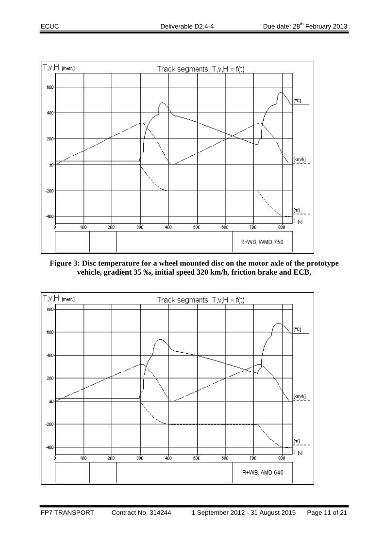
Figure 4: Disc temperature for an axle mounted disc on the trailer axle of the prototype vehicle, gradient 35 ‰, initial speed 320 km/h, friction brake and ECB
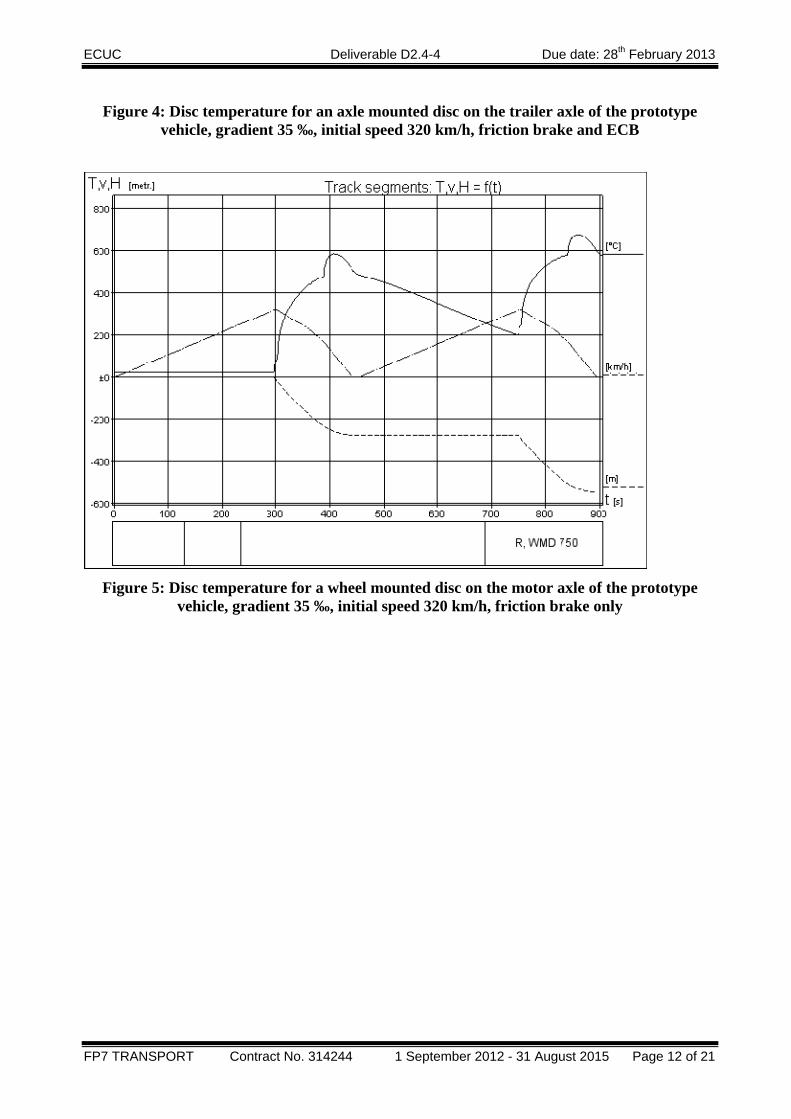
Figure 5: Disc temperature for a wheel mounted disc on the motor axle of the prototype
vehicle, gradient 35 ‰, initial speed 320 km/h, friction brake only
ECUC Deliverable D2.4-4 Due date: 28th February 2013
FP7 TRANSPORT Contract No. 314244 1 September 2012 - 31 August 2015 Page 13 of 21
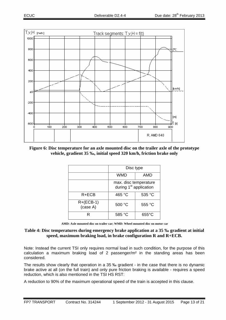
Figure 6: Disc temperature for an axle mounted disc on the trailer axle of the prototype
vehicle, gradient 35 ‰, initial speed 320 km/h, friction brake only
Disc type
WMD AMD
max. disc temperature during 1st application
R+ECB 465 °C 535 °C
R+(ECB-1) (case A) 500 °C 555 °C
R 585 °C 655°C
AMD: Axle mounted disc on trailer car; WMD: Wheel mounted disc on motor car Table 4: Disc temperatures during emergency brake application at a 35 ‰ gradient at initial
speed, maximum braking load, in brake configuration R and R+ECB.
Note: Instead the current TSI only requires normal load in such condition, for the purpose of this calculation a maximum braking load of 2 passenger/m² in the standing areas has been considered.
The results show clearly that operation in a 35 ‰ gradient - in the case that there is no dynamic brake active at all (on the full train) and only pure friction braking is available - requires a speed reduction, which is also mentioned in the TSI HS RST:
A reduction to 90% of the maximum operational speed of the train is accepted in this clause.
ECUC Deliverable D2.4-4 Due date: 28th February 2013
FP7 TRANSPORT Contract No. 314244 1 September 2012 - 31 August 2015 Page 14 of 21
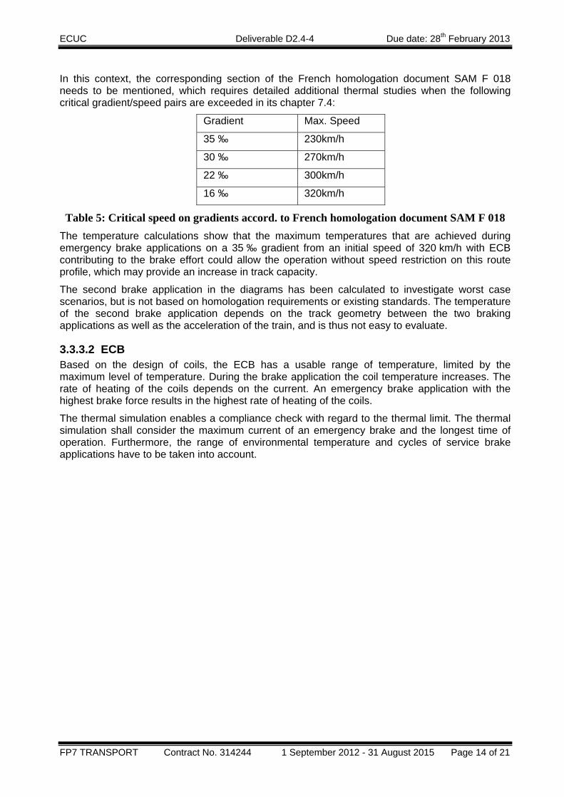
In this context, the corresponding section of the French homologation document SAM F 018 needs to be mentioned, which requires detailed additional thermal studies when the following critical gradient/speed pairs are exceeded in its chapter 7.4:
Gradient Max. Speed
35 ‰ 230km/h
30 ‰ 270km/h
22 ‰ 300km/h
16 ‰ 320km/h
Table 5: Critical speed on gradients accord. to French homologation document SAM F 018 The temperature calculations show that the maximum temperatures that are achieved during emergency brake applications on a 35 ‰ gradient from an initial speed of 320 km/h with ECB contributing to the brake effort could allow the operation without speed restriction on this route profile, which may provide an increase in track capacity.
The second brake application in the diagrams has been calculated to investigate worst case scenarios, but is not based on homologation requirements or existing standards. The temperature of the second brake application depends on the track geometry between the two braking applications as well as the acceleration of the train, and is thus not easy to evaluate.
3.3.3.2 ECB Based on the design of coils, the ECB has a usable range of temperature, limited by the maximum level of temperature. During the brake application the coil temperature increases. The rate of heating of the coils depends on the current. An emergency brake application with the highest brake force results in the highest rate of heating of the coils.
The thermal simulation enables a compliance check with regard to the thermal limit. The thermal simulation shall consider the maximum current of an emergency brake and the longest time of operation. Furthermore, the range of environmental temperature and cycles of service brake applications have to be taken into account.
ECUC Deliverable D2.4-4 Due date: 28th February 2013
FP7 TRANSPORT Contract No. 314244 1 September 2012 - 31 August 2015 Page 15 of 21
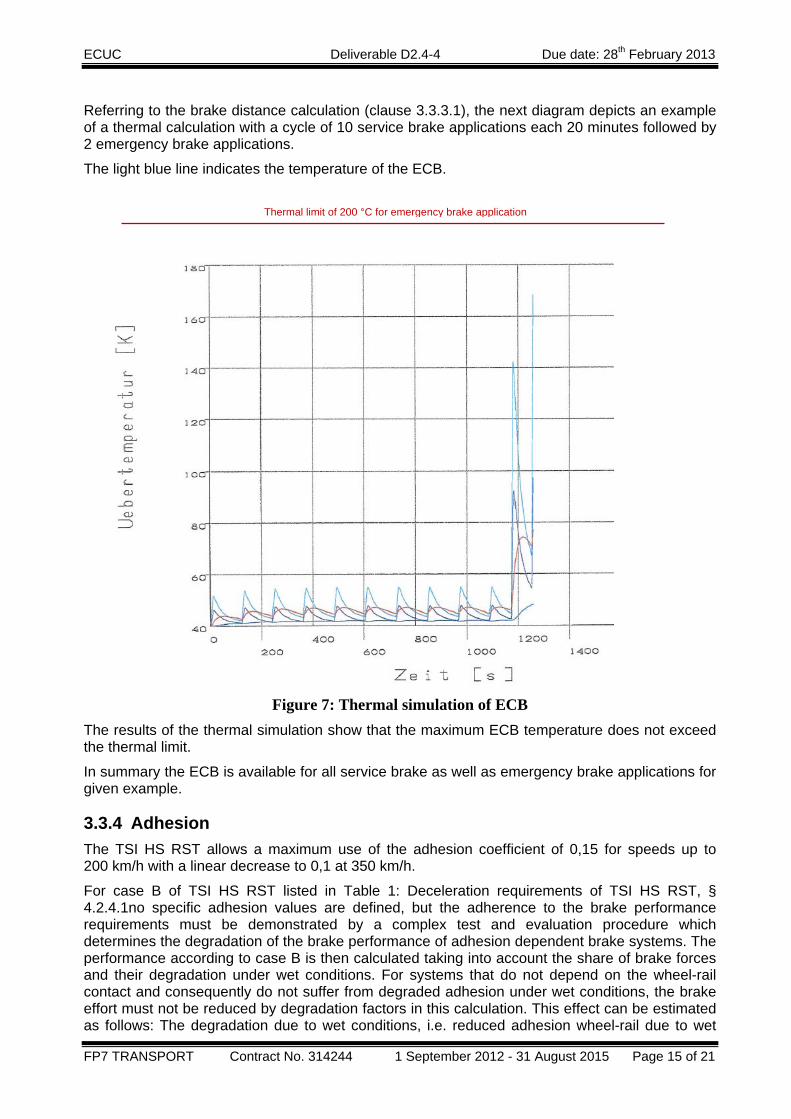
Referring to the brake distance calculation (clause 3.3.3.1), the next diagram depicts an example of a thermal calculation with a cycle of 10 service brake applications each 20 minutes followed by 2 emergency brake applications.
The light blue line indicates the temperature of the ECB.
Figure 7: Thermal simulation of ECB
The results of the thermal simulation show that the maximum ECB temperature does not exceed the thermal limit.
In summary the ECB is available for all service brake as well as emergency brake applications for given example.
3.3.4 Adhesion The TSI HS RST allows a maximum use of the adhesion coefficient of 0,15 for speeds up to 200 km/h with a linear decrease to 0,1 at 350 km/h.
For case B of TSI HS RST listed in Table 1: Deceleration requirements of TSI HS RST, § 4.2.4.1no specific adhesion values are defined, but the adherence to the brake performance requirements must be demonstrated by a complex test and evaluation procedure which determines the degradation of the brake performance of adhesion dependent brake systems. The performance according to case B is then calculated taking into account the share of brake forces and their degradation under wet conditions. For systems that do not depend on the wheel-rail contact and consequently do not suffer from degraded adhesion under wet conditions, the brake effort must not be reduced by degradation factors in this calculation. This effect can be estimated as follows: The degradation due to wet conditions, i.e. reduced adhesion wheel-rail due to wet
Thermal limit of 200 °C for emergency brake application
ECUC Deliverable D2.4-4 Due date: 28th February 2013
FP7 TRANSPORT Contract No. 314244 1 September 2012 - 31 August 2015 Page 16 of 21
track as well as reduced friction pad-disc due to wet pads, can be estimated to be in the range of 8 to 15 % depending on train conditions, initial speed etc., in a train with only friction brakes effective. In a train fitted additionally with eddy current brakes, the share of the eddy current brake force is 30 %, the friction brakes system contribute the remaining 70 %. Thus, the degradation which is only a matter of the friction brake, is also reduced to about 70 % of the initial value: the degradation of the brake performance is then reduced to about 6 – 11 % which is a significant improvement:
3.3.5 Brake forces According to TSI, the brake force of the ECB is defined without reference to the train configuration. The following limits apply:
‐ The limit of the ECB brake force during emergency braking is 360 kN per train.
‐ The limit of the ECB brake force during service brake applications is 180 kN per train.
‐ An additional limit is defined for a “2/3 service brake application” which is 105 kN per train.
A train having the configuration listed in Chapter 2, i.e. 4 motor and 4 trailer cars, will have a total nominal brake force of the ECB of 180kN, which could be available for service and emergency braking.
An interesting idea would be to use the full capacity of the ECB in maximum service brake on a single unit (i.e. 180 kN) while limiting the total effort in max service brake to 180 for a configuration consisting of 2 units. This would require a reliable management of the brake system to use the half of the available ECB effort when running in a multiple unit configuration. The design of such advanced control system is out of the current scope of ECUC.
The following part of this paragraph is taking into consideration the use of this innovative idea.
A train set up in “double traction”, i.e. consisting of 2 such 8-car-trains, will be able to deploy the brake force available only in emergency brake force, whereas in full service brake and 2/3 service brake, the brake force limit is constant at 105 kN or 180 kN, respectively.
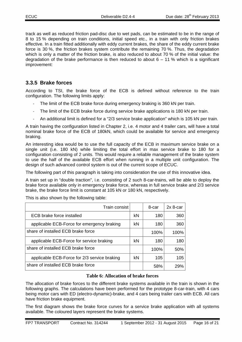
This is also shown by the following table:
Train consist 8-car 2x 8-car
ECB brake force installed kN 180 360
applicable ECB-Force for emergency braking kN 180 360 share of installed ECB brake force 100% 100%
applicable ECB-Force for service braking kN 180 180 share of installed ECB brake force 100% 50%
applicable ECB-Force for 2/3 service braking kN 105 105 share of installed ECB brake force 58% 29%
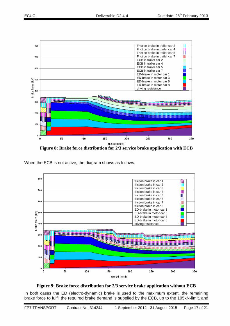
Table 6: Allocation of brake forces The allocation of brake forces to the different brake systems available in the train is shown in the following graphs. The calculations have been performed for the prototype 8-car-train, with 4 cars being motor cars with ED (electro-dynamic)-brake, and 4 cars being trailer cars with ECB. All cars have friction brake equipment.
The first diagram shows the brake force curves for a service brake application with all systems available. The coloured layers represent the brake systems.
ECUC Deliverable D2.4-4 Due date: 28th February 2013
FP7 TRANSPORT Contract No. 314244 1 September 2012 - 31 August 2015 Page 17 of 21
Figure 8: Brake force distribution for 2/3 service brake application with ECB
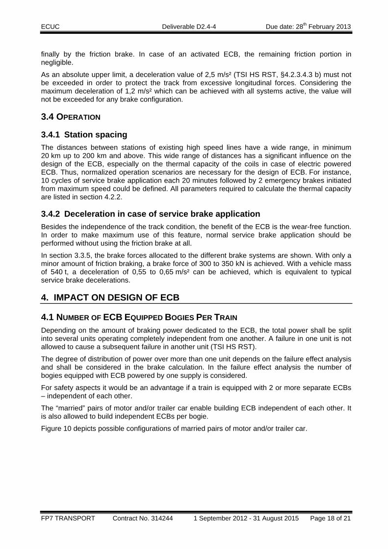
When the ECB is not active, the diagram shows as follows.
Figure 9: Brake force distribution for 2/3 service brake application without ECB In both cases the ED (electro-dynamic) brake is used to the maximum extent, the remaining brake force to fulfil the required brake demand is supplied by the ECB, up to the 105kN-limit, and
Friction brake in trailer car 2 Friction brake in trailer car 4 Friction brake in trailer car 5 Friction brake in trailer car 7 ECB in trailer car 2 ECB in trailer car 4 ECB in trailer car 5 ECB in trailer car 7 ED-brake in motor car 1 ED-brake in motor car 3 ED-brake in motor car 6 ED-brake in motor car 8 driving resistance
friction brake in car 1 friction brake in car 2 friction brake in car 3 friction brake in car 4 friction brake in car 5 friction brake in car 6 friction brake in car 7 friction brake in car 8 ED-brake in motor car 1 ED-brake in motor car 3 ED-brake in motor car 6 ED-brake in motor car 8 driving resistance
ECUC Deliverable D2.4-4 Due date: 28th February 2013
FP7 TRANSPORT Contract No. 314244 1 September 2012 - 31 August 2015 Page 18 of 21
finally by the friction brake. In case of an activated ECB, the remaining friction portion in negligible.
As an absolute upper limit, a deceleration value of 2,5 m/s² (TSI HS RST, §4.2.3.4.3 b) must not be exceeded in order to protect the track from excessive longitudinal forces. Considering the maximum deceleration of 1,2 m/s² which can be achieved with all systems active, the value will not be exceeded for any brake configuration.
3.4 OPERATION
3.4.1 Station spacing The distances between stations of existing high speed lines have a wide range, in minimum 20 km up to 200 km and above. This wide range of distances has a significant influence on the design of the ECB, especially on the thermal capacity of the coils in case of electric powered ECB. Thus, normalized operation scenarios are necessary for the design of ECB. For instance, 10 cycles of service brake application each 20 minutes followed by 2 emergency brakes initiated from maximum speed could be defined. All parameters required to calculate the thermal capacity are listed in section 4.2.2.
3.4.2 Deceleration in case of service brake application Besides the independence of the track condition, the benefit of the ECB is the wear-free function. In order to make maximum use of this feature, normal service brake application should be performed without using the friction brake at all.
In section 3.3.5, the brake forces allocated to the different brake systems are shown. With only a minor amount of friction braking, a brake force of 300 to 350 kN is achieved. With a vehicle mass of 540 t, a deceleration of 0,55 to 0,65 m/s² can be achieved, which is equivalent to typical service brake decelerations.
4. IMPACT ON DESIGN OF ECB
4.1 NUMBER OF ECB EQUIPPED BOGIES PER TRAIN Depending on the amount of braking power dedicated to the ECB, the total power shall be split into several units operating completely independent from one another. A failure in one unit is not allowed to cause a subsequent failure in another unit (TSI HS RST).
The degree of distribution of power over more than one unit depends on the failure effect analysis and shall be considered in the brake calculation. In the failure effect analysis the number of bogies equipped with ECB powered by one supply is considered.
For safety aspects it would be an advantage if a train is equipped with 2 or more separate ECBs – independent of each other.
The “married” pairs of motor and/or trailer car enable building ECB independent of each other. It is also allowed to build independent ECBs per bogie.
Figure 10 depicts possible configurations of married pairs of motor and/or trailer car.

ECUC Deliverable D2.4-4 Due date: 28th February 2013
FP7 TRANSPORT Contract No. 314244 1 September 2012 - 31 August 2015 Page 19 of 21
Figure 10: examples of train configuration
4.2 BRAKE PERFORMANCE Depending on the requirements from TSI (TSI IS clause 4.2.5 and TSI HS RS 4.2.3.4.3 b case 1 and case 2, TSI HS RS clause 4.2.4.5) and the train configuration the brake force levels for ECB can be defined.
In the case of the described prototype, a “married” pair of motor and/or trailer cars equipped with ECBs allows a brake force of 22,5 kN for service brake application (i.e. 180 kN per train consisting of 8 married pairs motor and/or trailer car).
For emergency brake application a brake force of 45 kN for ECB equipped trains is allowed (i.e. 360 kN per train consisting of 8 married pairs of motor and/or trailer car).
The ECBs can be equipped in 2, 3 or 4 bogies in each “married” pair of motor and/or trailer cars. Note: the current serial installations only use ECBs on trailer bogies. Installation on motor bogies needs more studying (mechanical installation, weight/axle load, control….). It has been tested on prototypes only.
Table 7 depicts the brake forces per ECB depending on the number of installed ECB, which can be equipped per “married” pair of motor and/or trailer car for service and emergency braking. This model may be expanded to a whole train configuration.
Number of ECBs 2 3 4 Service brake 11,25 kN per ECB 7,50 kN per ECB 5,625 kN per ECB
Emergency brake 22,50 kN per ECB 15,00 kN per ECB 11,25 kN per ECB
Table 7: Demands on brake force depending on the number of equipped ECBs in case of the depicted example of married pair of cars
ECUC Deliverable D2.4-4 Due date: 28th February 2013
FP7 TRANSPORT Contract No. 314244 1 September 2012 - 31 August 2015 Page 20 of 21
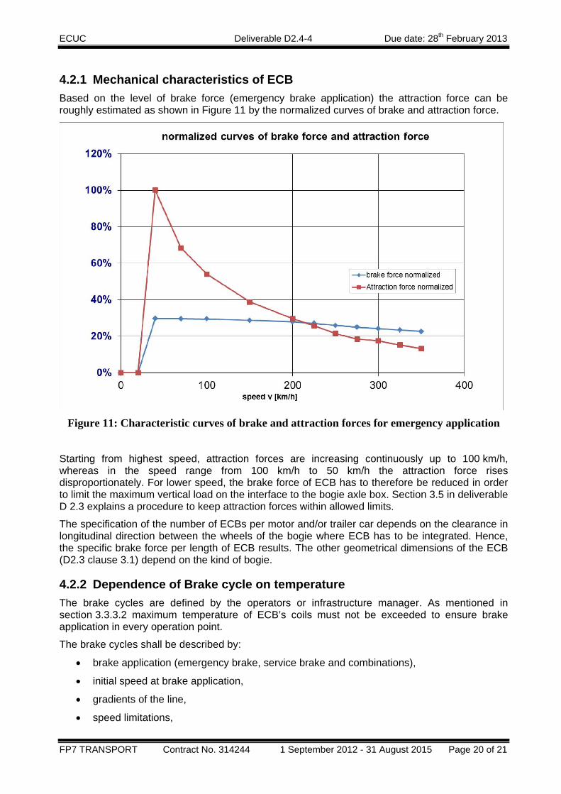
4.2.1 Mechanical characteristics of ECB Based on the level of brake force (emergency brake application) the attraction force can be roughly estimated as shown in Figure 11 by the normalized curves of brake and attraction force.
Figure 11: Characteristic curves of brake and attraction forces for emergency application
Starting from highest speed, attraction forces are increasing continuously up to 100 km/h, whereas in the speed range from 100 km/h to 50 km/h the attraction force rises disproportionately. For lower speed, the brake force of ECB has to therefore be reduced in order to limit the maximum vertical load on the interface to the bogie axle box. Section 3.5 in deliverable D 2.3 explains a procedure to keep attraction forces within allowed limits.
The specification of the number of ECBs per motor and/or trailer car depends on the clearance in longitudinal direction between the wheels of the bogie where ECB has to be integrated. Hence, the specific brake force per length of ECB results. The other geometrical dimensions of the ECB (D2.3 clause 3.1) depend on the kind of bogie.
4.2.2 Dependence of Brake cycle on temperature The brake cycles are defined by the operators or infrastructure manager. As mentioned in section 3.3.3.2 maximum temperature of ECB’s coils must not be exceeded to ensure brake application in every operation point.
The brake cycles shall be described by:
• brake application (emergency brake, service brake and combinations),
• initial speed at brake application,
• gradients of the line,
• speed limitations,

ECUC Deliverable D2.4-4 Due date: 28th February 2013
FP7 TRANSPORT Contract No. 314244 1 September 2012 - 31 August 2015 Page 21 of 21
• duty cycles with delay of driving, braking, stopping and repetitions,
• minimum train deceleration,
• maximum train acceleration.
4.3 AIR GAP According to deliverable D 2.2 section 3.3.1, the contact between ECB and rail shall be avoided under normal operating conditions for all track geometries on which the train can operate. Thereby the normal operation conditions are specified in accordance to IEC61373 for axle mounted components (clause 8.1, table 1, figure 5).
Nevertheless, independent of the magnetization of ECB, during brake application, a contact between the ECB and the rail may occur, induced by dynamic effects from the bogie or the infrastructure, causing deformation of the ECB mechanical structure.
Due to high accelerations caused by these dynamic effects, ECB will touch the rail for a short time. The construction of ECB has to consider these additional loads in accordance to IEC 61373, section 10.5, table 3 without any functional restrictions: category 2 when in upper position and category 3 when in braking position.
4.4 FORCE AND PRESSURE CONTROL The requirements of TSI have no direct impact to the force and pressure control. The safety requirements shall be considered by design and construction of the components.
4.5 POWER CONSUMPTION The ECB needs a powerful energy supply. The number of separately energy supplies is defined by the safety analysis procedure and the consideration of the degraded modes as defined in A and B of the TSI HS RS, section 4.2.4.1.
The design parameters of the energy supply depend on the power consumption and the number of ECBs per energy supply. The design parameters of ECB are listed in deliverable D 2.3 section 3.6.
The voltage level and other properties of the power supply depend on isolation requirements and the number of turns per coil of ECB. The parameters are listed in deliverable D 2.3 section 3.7.