Eddy Current Array for Aircraft Engine Component Inspection · Today, eddy current arrays are used...
15
10 th International Symposium on NDT in Aerospace 1 License: https://creativecommons.org/licenses/by-nd/4.0/ Eddy Current Array for Aircraft Engine Component Inspection André LAMARRE 1 1 Olympus Scientific Solutions Americas, Quebec City, Canada Contact e-mail: [email protected] Abstract Components of aircraft engines are submitted to very high stresses and temperatures during operation. Consequently, to assure the safety of the public, the integrity of these components must be ensured with reliable inspection methods. While the use of remote visual and dye penetrant inspection is widespread, the aircraft engine manufacturing and maintenance industries now benefit from recent developments in magnetic methods, namely eddy current array. Eddy current testing (ECT) has long been considered the technique of choice to detect and size cracks on the surface of aircraft engine components. Unfortunately, inspections using single-coil eddy current probes can be slow with results that vary from operator to operator. In these and other respects, eddy current array (ECA) technology has advanced the technique significantly. The use of arrays helps to rapidly achieve full coverage of inspected zones while maintaining a high resolution. Portable eddy current electronics enable the use of large arrays and the image resulting from the software’s data processing helps the operator perform a reliable analysis. Probe holders and mechanical supports are continuously being developed to address the different applications of ECA for engines. Today, eddy current arrays are used by major aircraft engine manufacturers and maintenance companies for the assessment of engine components, such as dovetails, blade attachments, and turbine discs. This presentation will review how eddy current array technology contributes to public safety.
Transcript of Eddy Current Array for Aircraft Engine Component Inspection · Today, eddy current arrays are used...

10th International Symposium on NDT in Aerospace
1 License: https://creativecommons.org/licenses/by-nd/4.0/
Eddy Current Array for Aircraft Engine
Component Inspection
André LAMARRE 1 1 Olympus Scientific Solutions Americas, Quebec City, Canada
Contact e-mail: [email protected]
Abstract
Components of aircraft engines are submitted to very high stresses and temperatures during
operation. Consequently, to assure the safety of the public, the integrity of these components
must be ensured with reliable inspection methods. While the use of remote visual and dye
penetrant inspection is widespread, the aircraft engine manufacturing and maintenance
industries now benefit from recent developments in magnetic methods, namely eddy current
array.
Eddy current testing (ECT) has long been considered the technique of choice to detect
and size cracks on the surface of aircraft engine components. Unfortunately, inspections
using single-coil eddy current probes can be slow with results that vary from operator to
operator. In these and other respects, eddy current array (ECA) technology has advanced the
technique significantly. The use of arrays helps to rapidly achieve full coverage of inspected
zones while maintaining a high resolution. Portable eddy current electronics enable the use
of large arrays and the image resulting from the software’s data processing helps the operator
perform a reliable analysis. Probe holders and mechanical supports are continuously being
developed to address the different applications of ECA for engines.
Today, eddy current arrays are used by major aircraft engine manufacturers and
maintenance companies for the assessment of engine components, such as dovetails, blade
attachments, and turbine discs. This presentation will review how eddy current array
technology contributes to public safety.
Olympus Scientific Solutions Americas | Andre LAMARRE
Eddy Current Array for Aircraft Engine Component Inspection
1. Eddy Current Array (ECA) Technology
2. ECA Equipment
3. Engine Applications
4. Conclusion
Agenda
Eddy Current Array Technology
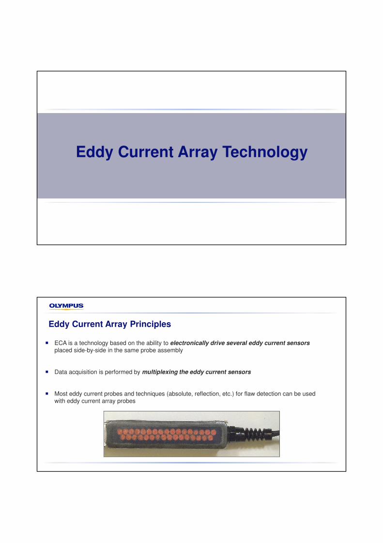
Eddy Current Array Principles
� ECA is a technology based on the ability to electronically drive several eddy current sensors
placed side-by-side in the same probe assembly
� Data acquisition is performed by multiplexing the eddy current sensors
� Most eddy current probes and techniques (absolute, reflection, etc.) for flaw detection can be used with eddy current array probes

Eddy Current Array—Advantages
� Provides larger coverage in a single probe pass while maintaining high resolution
� Improves flaw detection and sizing with C-scan imaging
� Enables inspection of complex shapes with probes customized to the profile of parts
ECA – Signal Representation
ECA probe over a flaw Each coil produces asignal
Color-coded signal amplitude displayed in the C-scan
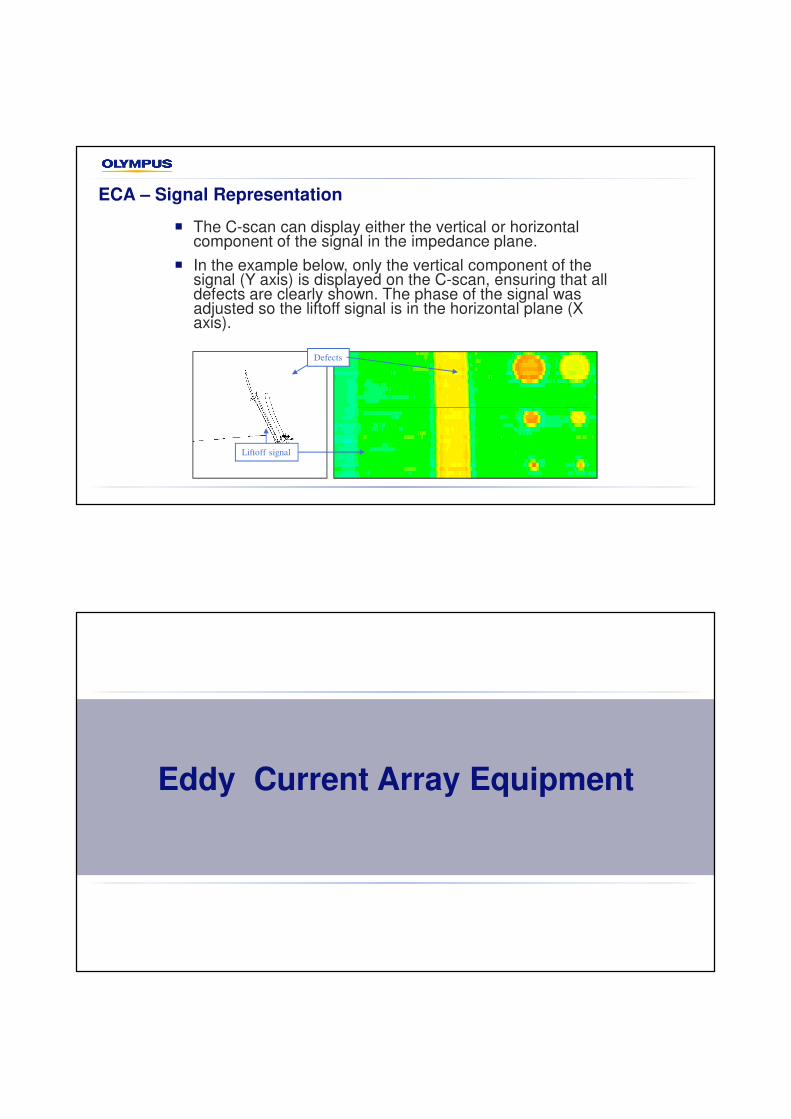
ECA – Signal Representation
� The C-scan can display either the vertical or horizontal component of the signal in the impedance plane.
� In the example below, only the vertical component of the signal (Y axis) is displayed on the C-scan, ensuring that all defects are clearly shown. The phase of the signal was adjusted so the liftoff signal is in the horizontal plane (X axis).
Liftoff signal
Defects
Eddy Current Array Equipment

9
General Hardware Features
OMNI-P-ECT4
− Conventional ECT only
− 4 input channels
− Frequency ranges from
20 Hz to 6 MHz
− Dual frequency operation
− 2 encoder inputs
− 3 alarm outputs
− 1 analog output
10
ECA Probes
� Can be optimized for
different applications
� Can be shaped to the
part to inspect
ECA — Probe Parameters
11
� Frequency (f)
� Number of elements (n)
� Resolution (r) (also depends on the coil configuration)
� Coverage (C)
Example of an absolute bridge probe
C
r
12
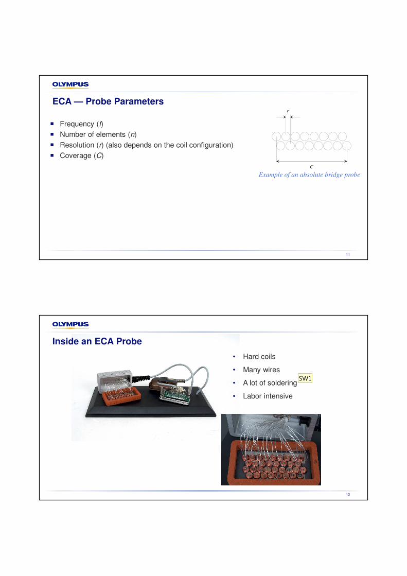
Inside an ECA Probe
• Hard coils
• Many wires
• A lot of soldering
• Labor intensive
SW1

Diapositive 12
SW1 I would call this soldering and not welding.Sarah Williams; 2018-05-28

ECA Hard Coiled Array VS Printed Circuit Board (PCB) Array
Traditional hard coil sensors� Pros:
� Different type and size of coils
� Cons:
� Time consuming
� Repeatability and coil matching
� Expensive
Flexible array on PCB film
� Pros:
� Excellent repeatability and coil matching
� Versatility, i.e., can be attached to holders of different shapes
� Affordable price
� Cons:
� Price/time for the initial film
Engine Applications
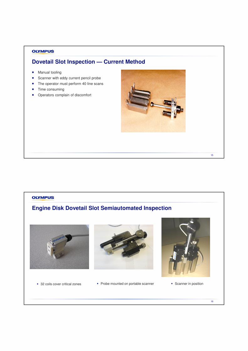
Dovetail Slot Inspection — Current Method
� Manual tooling
� Scanner with eddy current pencil probe
� The operator must perform 40 line scans
� Time consuming
� Operators complain of discomfort
15
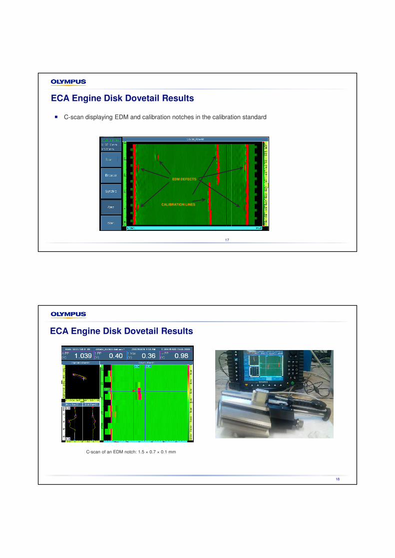
Engine Disk Dovetail Slot Semiautomated Inspection
16
� 32 coils cover critical zones � Probe mounted on portable scanner � Scanner in position
17
� C-scan displaying EDM and calibration notches in the calibration standard
EDM DEFECTS
CALIBRATION LINES
ECA Engine Disk Dovetail Results
18
C-scan of an EDM notch: 1.5 × 0.7 × 0.1 mm
ECA Engine Disk Dovetail Results

New Engine Disk Slot Inspection System
Scanner improved with OmniScan®
flaw detector remote control
Engine Fan Blade Inspection
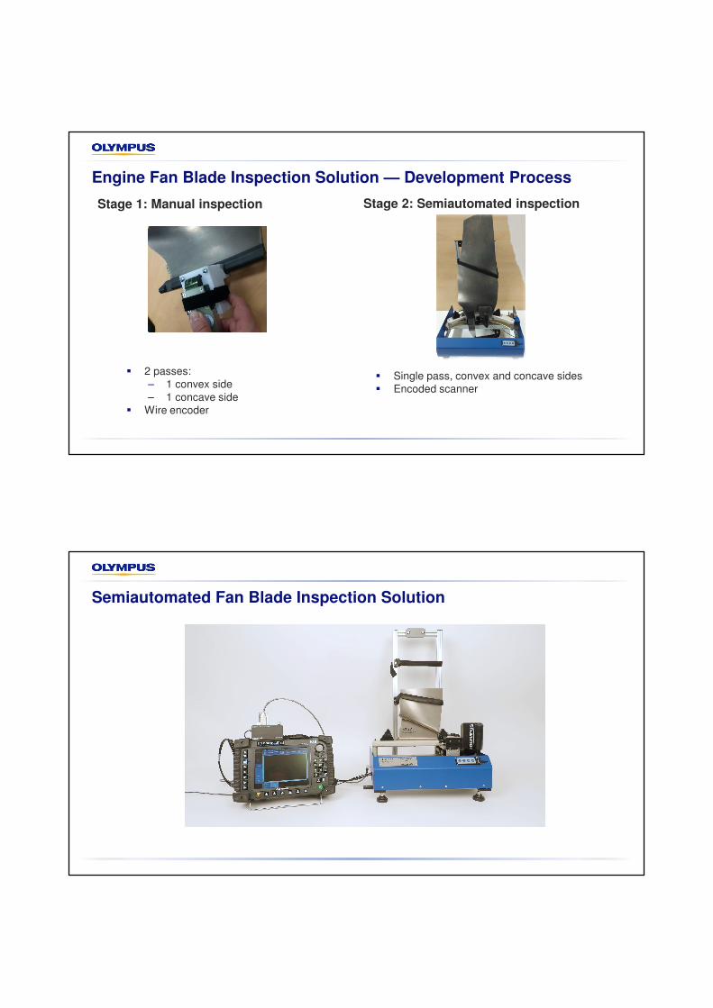
Stage 2: Semiautomated inspectionStage 1: Manual inspection
Engine Fan Blade Inspection Solution — Development Process
� 2 passes:
– 1 convex side
– 1 concave side
� Wire encoder
� Single pass, convex and concave sides
� Encoded scanner
Semiautomated Fan Blade Inspection Solution

Conclusion
ECA Advantages for Aircraft Engine Inspection
� ECA probes cover large areas in a single pass
� Improved Probability of Detection due to full coverage and C-scan imaging
� Probes can be adapted to the complex shapes of components
� Flexible ECA can be used interchangeably with probe holders of different shapes
� Can be used on-site for aircraft engine component inspection during maintenance
� Referenced in procedures for aircraft and engine maintenance