ED01-707_FT~FVM series.pdf
56
- Cooling Only - F-Series ED 01 - 707
Transcript of ED01-707_FT~FVM series.pdf
- Cooling Only -
F-Series
ED 01 - 707
ED01-707
Room Air Conditioners F-Series 1
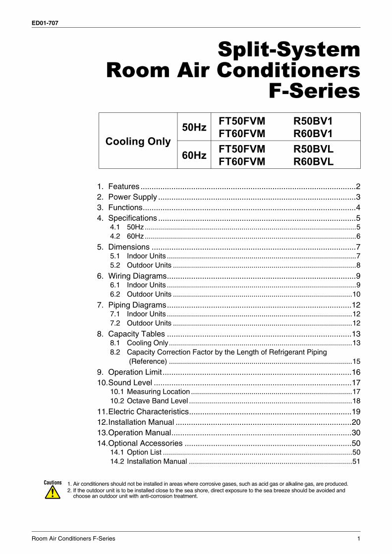
Split-SystemRoom Air Conditioners
F-Series
1. Features ..................................................................................................22. Power Supply ..........................................................................................33. Functions.................................................................................................44. Specifications ..........................................................................................5
4.1 50Hz .........................................................................................................54.2 60Hz .........................................................................................................6
5. Dimensions .............................................................................................75.1 Indoor Units ..............................................................................................75.2 Outdoor Units ...........................................................................................8
6. Wiring Diagrams......................................................................................96.1 Indoor Units ..............................................................................................96.2 Outdoor Units .........................................................................................10
7. Piping Diagrams....................................................................................127.1 Indoor Units ............................................................................................127.2 Outdoor Units .........................................................................................12
8. Capacity Tables ....................................................................................138.1 Cooling Only...........................................................................................138.2 Capacity Correction Factor by the Length of Refrigerant Piping
(Reference) ...........................................................................................15
9. Operation Limit......................................................................................1610.Sound Level ..........................................................................................17
10.1 Measuring Location ................................................................................1710.2 Octave Band Level .................................................................................18
11.Electric Characteristics..........................................................................1912.Installation Manual ................................................................................2013.Operation Manual..................................................................................3014.Optional Accessories ............................................................................50
14.1 Option List ..............................................................................................5014.2 Installation Manual .................................................................................51
Cooling Only50Hz FT50FVM
FT60FVMR50BV1R60BV1
60Hz FT50FVMFT60FVM
R50BVLR60BVL
Features ED01-707
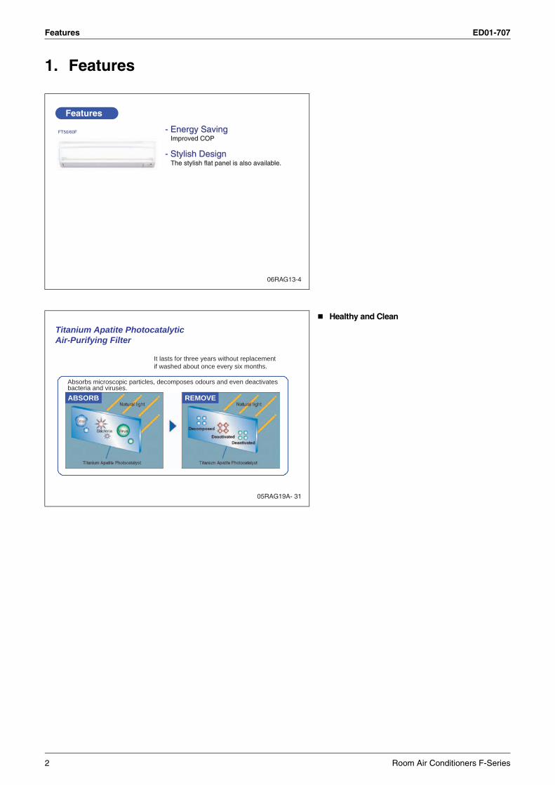
1. Features
Healthy and Clean
Features
- Energy Saving- Energy SavingImproved COPImproved COP
- Stylish Design- Stylish DesignThe stylish flat panel is also available.The stylish flat panel is also available.
FT50/60F
06RAG13-4
05RAG19A- 31
It lasts for three years without replacementif washed about once every six months.
ABSORB REMOVE
Absorbs microscopic particles, decomposes odours and even deactivatesbacteria and viruses.
Titanium Apatite PhotocatalyticAir-Purifying Filter
2 Room Air Conditioners F-Series
ED01-707 Power Supply
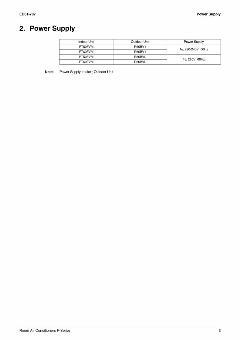
2. Power Supply
Note: Power Supply Intake ; Outdoor Unit
Indoor Unit Outdoor Unit Power Supply
FT50FVM R50BV11φ, 220-240V, 50Hz
FT60FVM R60BV1
FT50FVM R50BVL1φ, 220V, 60Hz
FT60FVM R60BVL
Room Air Conditioners F-Series 3
Functions ED01-707
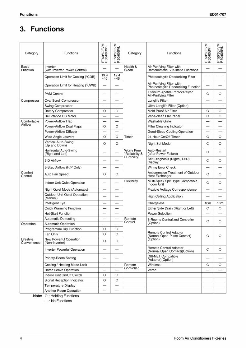
3. Functions
Category Functions
FT
50/6
0FV
MR
50/6
0BV
1
FT
50/6
0FV
MR
50/6
0BV
L
Category Functions
FT
50/6
0FV
MR
50/6
0BV
1
FT
50/6
0FV
MR
50/6
0BV
L
Basic Function
Inverter (with Inverter Power Control) — — Health &
CleanAir Purifying Filter with Bacteriostatic, Virustatic Functions — —
Operation Limit for Cooling (°CDB) 19.4~46
19.4~46 Photocatalytic Deodorizing Filter — —
Operation Limit for Heating (°CWB) — — Air Purifying Filter with Photocatalytic Deodorizing Function — —
PAM Control — — Titanium Apatite PhotocatalyticAir-Purifying Filter
Compressor Oval Scroll Compressor — — Longlife Filter — —
Swing Compressor — — Ultra-Longlife Filter (Option) — —
Rotary Compressor Mold Proof Air Filter
Reluctance DC Motor — — Wipe-clean Flat Panel
Comfortable Airflow
Power-Airflow Flap — — Washable Grille — —
Power-Airflow Dual Flaps Filter Cleaning Indicator — —
Power-Airflow Diffuser — — Good-Sleep Cooling Operation — —
Wide-Angle Louvers Timer 24-Hour On/Off Timer
Vertical Auto-Swing(Up and Down) Night Set Mode
Horizontal Auto-Swing(Right and Left) — — Worry Free
“Reliability & Durability”
Auto-Restart(after Power Failure)
3-D Airflow — — Self-Diagnosis (Digital, LED) Display
3-Step Airflow (H/P Only) — — Wiring Error Check — —
Comfort Control Auto Fan Speed Anticorrosion Treatment of Outdoor
Heat Exchanger
Indoor Unit Quiet Operation — — Flexibility Multi-Split / Split Type Compatible Indoor Unit
Night Quiet Mode (Automatic) — — Flexible Voltage Correspondence — —
Outdoor Unit Quiet Operation (Manual) — — High Ceiling Application — —
Intelligent Eye — — Chargeless 10m 10m
Quick Warming Function — — Either Side Drain (Right or Left)
Hot-Start Function — — Power Selection — —
Automatic Defrosting — — Remote Control
5-Rooms Centralized Controller (Option)Operation Automatic Operation — —
Programme Dry FunctionRemote Control Adaptor(Normal Open-Pulse Contact)(Option)
Fan Only
Lifestyle Convenience
New Powerful Operation(Non-Inverter)
Inverter Powerful Operation — — Remote Control Adaptor (Normal Open Contact)(Option)
Priority-Room Setting — — DIII-NET Compatible (Adaptor)(Option) — —
Cooling / Heating Mode Lock — — Remote Controller
Wireless
Home Leave Operation — — Wired — —
Indoor Unit On/Off Switch
Signal Reception Indicator
Temperature Display — —
Another Room Operation — —
Note: : Holding Functions— : No Functions
4 Room Air Conditioners F-Series
ED01-707 Specifications
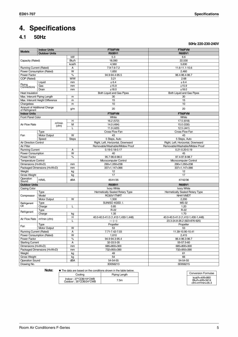
4. Specifications4.1 50Hz
50Hz 220-230-240V
Note: The data are based on the conditions shown in the table below.
ModelsIndoor Units FT50FVM FT60FVMOutdoor Units R50BV1 R60BV1
Capacity (Rated)kW 5.3 6.6
Btu/h 18,090 22,530kcal/h 4,560 5,630
Running Current (Rated) A 7.9-7.6-7.2 11.6-11.1-10.6Power Consumption (Rated) W 1,650 2,460Power Factor % 94.9-94.4-95.5 96.4-96.4-96.7COP (Rated) W/W 3.21 2.68
Piping Connections
Liquid mm φ 6.4 φ 6.4Gas mm φ15.9 φ15.9Drain mm φ18.0 φ18.0
Heat Insulation Both Liquid and Gas Pipes Both Liquid and Gas PipesMax. Interunit Piping Length m 30 30Max. Interunit Height Difference m 15 15Chargeless m 10 10Amount of Additional Chargeof Refrigerant g/m 20 20
Indoor Units FT50FVM FT60FVMFront Panel Color White White
Air Flow Rate m³/min(cfm)
H 16.2 (572) 17.5 (618)M 14.0 (494) 15.0 (530)L 11.9 (420) 12.5 (441)
FanType Cross Flow Fan Cross Flow FanMotor Output W 43 43Speed Steps 5 Steps, Auto 5 Steps, Auto
Air Direction Control Right, Left, Horizontal, Downward Right, Left, Horizontal, DownwardAir Filter Removable/Washable/Mildew Proof Removable/Washable/Mildew ProofRunning Current A 0.19-0.18-0.17 0.21-0.20-0.19Power Consumption W 40 45Power Factor % 95.7-96.6-98.0 97.4-97.8-98.7Temperature Control Microcomputer Control Microcomputer ControlDimensions (H×W×D) mm 290×1,050×238 290×1,050×238Packaged Dimensions (H×W×D) mm 337×1,147×366 337×1,147×366Weight kg 12 12Gross Weight kg 17 17Operation Sound H/M/L dBA 45/41/35 47/42/36
Outdoor Units R50BV1 R60BV1Casing Color Ivory White Ivory White
CompressorType Hermetically Sealed Rotary Type Hermetically Sealed Rotary TypeModel RC60V1TNRT NH41VMDTMotor Output W 1,500 2,200
Refrigerant Oil
Type SUNISO 4GSD. I. MS-32Charge L 0.85 1.20
RefrigerantType R-22 R-22Charge kg 1.35 1.70
Air Flow Rate m³/min (cfm)H 40.0-40.5-41.0 (1,412-1,430-1,448) 40.0-40.5-41.0 (1,412-1,430-1,448)L — (—) 23.3-24.8-26.2 (823-876-925)
FanType Propeller PropellerMotor Output W 53 53
Running Current (Rated) A 7.71-7.42-7.03 11.39-10.90-10.41Power Consumption (Rated) W 1,610 2,415Power Factor % 94.9-94.3-95.4 96.4-96.3-96.7Starting Current A 32-33.5-35 55-57.5-60Dimensions (H×W×D) mm 685×800×300 685×800×300Packaged Dimensions (H×W×D) mm 732×955×390 732×955×390Weight kg 49 61Gross Weight kg 54 66Operation Sound dBA 54-54-55 54-54-55Drawing No. 3D056213 3D056215
Conversion Formulae
kcal/h=kW×860Btu/h=kW×3414
cfm=m³/min×35.3
Cooling Piping Length
Indoor ; 27°CDB/19°CWB Outdoor ; 35°CDB/24°CWB 7.5m
Room Air Conditioners F-Series 5
Specifications ED01-707
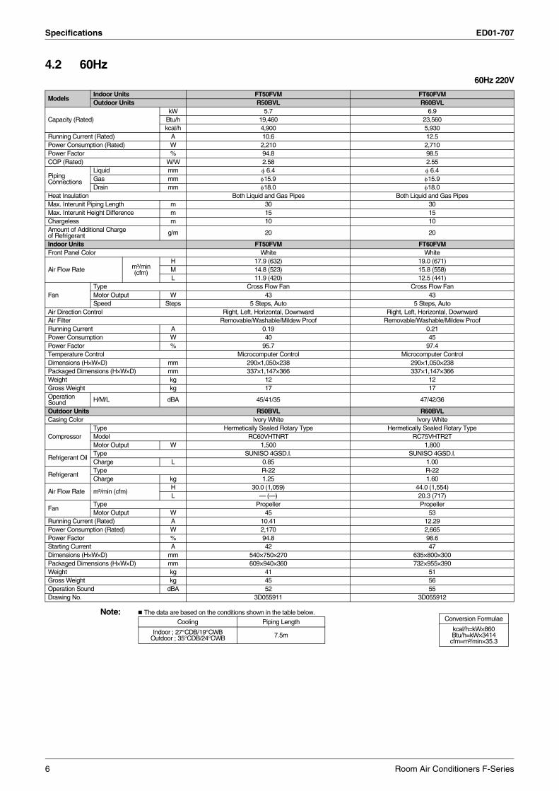
4.2 60Hz60Hz 220V
Note: The data are based on the conditions shown in the table below.
ModelsIndoor Units FT50FVM FT60FVMOutdoor Units R50BVL R60BVL
Capacity (Rated)kW 5.7 6.9
Btu/h 19,460 23,560kcal/h 4,900 5,930
Running Current (Rated) A 10.6 12.5Power Consumption (Rated) W 2,210 2,710Power Factor % 94.8 98.5COP (Rated) W/W 2.58 2.55
Piping Connections
Liquid mm φ 6.4 φ 6.4Gas mm φ15.9 φ15.9Drain mm φ18.0 φ18.0
Heat Insulation Both Liquid and Gas Pipes Both Liquid and Gas PipesMax. Interunit Piping Length m 30 30Max. Interunit Height Difference m 15 15Chargeless m 10 10Amount of Additional Chargeof Refrigerant g/m 20 20
Indoor Units FT50FVM FT60FVMFront Panel Color White White
Air Flow Rate m³/min(cfm)
H 17.9 (632) 19.0 (671)M 14.8 (523) 15.8 (558)L 11.9 (420) 12.5 (441)
FanType Cross Flow Fan Cross Flow FanMotor Output W 43 43Speed Steps 5 Steps, Auto 5 Steps, Auto
Air Direction Control Right, Left, Horizontal, Downward Right, Left, Horizontal, DownwardAir Filter Removable/Washable/Mildew Proof Removable/Washable/Mildew ProofRunning Current A 0.19 0.21Power Consumption W 40 45Power Factor % 95.7 97.4Temperature Control Microcomputer Control Microcomputer ControlDimensions (H×W×D) mm 290×1,050×238 290×1,050×238Packaged Dimensions (H×W×D) mm 337×1,147×366 337×1,147×366Weight kg 12 12Gross Weight kg 17 17Operation Sound H/M/L dBA 45/41/35 47/42/36
Outdoor Units R50BVL R60BVLCasing Color Ivory White Ivory White
CompressorType Hermetically Sealed Rotary Type Hermetically Sealed Rotary TypeModel RC60VHTNRT RC75VHTR2TMotor Output W 1,500 1,800
Refrigerant OilType SUNISO 4GSD.I. SUNISO 4GSD.I.Charge L 0.85 1.00
RefrigerantType R-22 R-22Charge kg 1.25 1.60
Air Flow Rate m³/min (cfm)H 30.0 (1,059) 44.0 (1,554)L — (—) 20.3 (717)
FanType Propeller PropellerMotor Output W 45 53
Running Current (Rated) A 10.41 12.29Power Consumption (Rated) W 2,170 2,665Power Factor % 94.8 98.6Starting Current A 42 47Dimensions (H×W×D) mm 540×750×270 635×800×300Packaged Dimensions (H×W×D) mm 609×940×360 732×955×390Weight kg 41 51Gross Weight kg 45 56Operation Sound dBA 52 55Drawing No. 3D055911 3D055912
Conversion Formulae
kcal/h=kW×860Btu/h=kW×3414
cfm=m³/min×35.3
Cooling Piping Length
Indoor ; 27°CDB/19°CWB Outdoor ; 35°CDB/24°CWB 7.5m
6 Room Air Conditioners F-Series
ED01-707 Dimensions
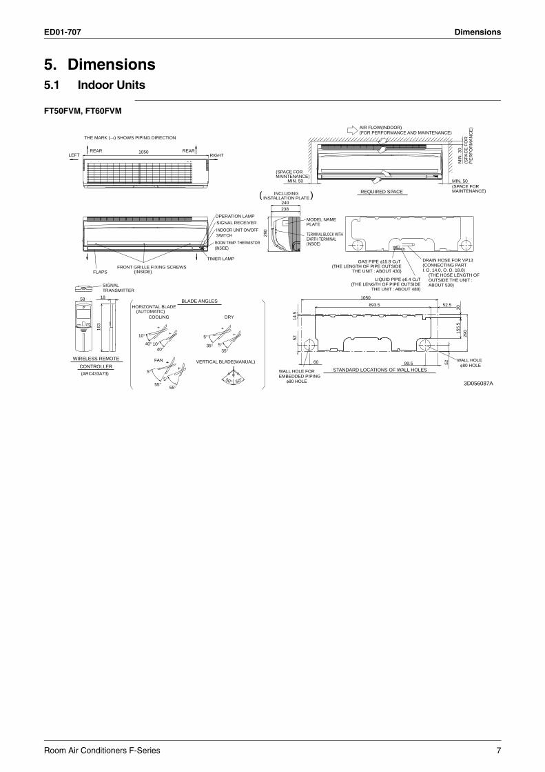
5. Dimensions5.1 Indoor Units
FT50FVM, FT60FVM
LEFTREAR
FAN
COOLING DRY
FLAPS
SIGNALTRANSMITTER
REARRIGHT
(ARC433A73)
THE MARK (→) SHOWS PIPING DIRECTION
1050
TIMER LAMP
(INSIDE)
OPERATION LAMP
ROOM TEMP. THERMISTOR(INSIDE)
SIGNAL RECEIVER
INDOOR UNIT ON/OFFSWITCH
FRONT GRILLE FIXING SCREWS
VERTICAL BLADE(MANUAL)
BLADE ANGLES
(AUTOMATIC)HORIZONTAL BLADE
16
3
WIRELESS REMOTE
1858
CONTROLLER
50° 50°
40°5°10°
40°10° 35° 5°
35°
5°
55°5°
55°
EARTH TERMINALTERMINAL BLOCK WITH
PLATEMODEL NAME
(INSIDE)
240
29
0
238
)INSTALLATION PLATEINCLUDING(
(FOR PERFORMANCE AND MAINTENANCE)
MAINTENANCE)(SPACE FOR
MIN
. 3
0
MIN. 50
PE
RF
OR
MA
NC
E)
(SP
AC
E F
OR
REQUIRED SPACE
MIN. 50
AIR FLOW(INDOOR)
MAINTENANCE)(SPACE FOR
OUTSIDE THE UNIT :(THE HOSE LENGTH OF
I. D. 14.0, O. D. 18.0)(CONNECTING PARTDRAIN HOSE FOR VP13
THE UNIT : ABOUT 430)(THE LENGTH OF PIPE OUTSIDE
GAS PIPE φ15.9 CuT
THE UNIT : ABOUT 480)(THE LENGTH OF PIPE OUTSIDE
LIQUID PIPE φ6.4 CuTABOUT 530)
1050
15
5.5
52
99.5
14
.5
29
0
52.5893.5
60 52
30
φ80 HOLE
WALL HOLE FOR φ80 HOLE
WALL HOLE
STANDARD LOCATIONS OF WALL HOLESEMBEDDED PIPING
3D056087A
Room Air Conditioners F-Series 7
Dimensions ED01-707
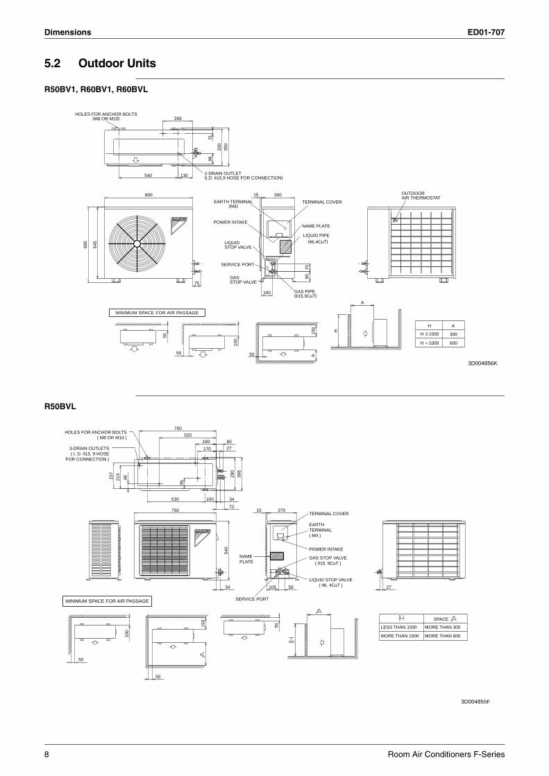
5.2 Outdoor Units
R50BV1, R60BV1, R60BVL
R50BVL
MINIMUM SPACE FOR AIR PASSAGE
HOLES FOR ANCHOR BOLTS(M8 OR M10)
68
5
64
5
540
800
50
50
269
130
75
2-DRAIN OUTLET(I.D. φ15.9 HOSE FOR CONNECTION)
EARTH TERMINAL(M4)
31
98
POWER INTAKE
SERVICE PORT
33
0
LIQUIDSTOP VALVE
GASSTOP VALVE
35
0
10
0
50
15
100
300
GAS PIPE(φ15.9CuT)
NAME PLATE
TERMINAL COVER
LIQUID PIPE(φ6.4CuT)
70
95
15
0A
H
A
OUTDOORAIR THERMOSTAT
H
H <=
=
H
1000
1000
600
300
A
3D004856K
HOLES FOR ANCHOR BOLTS( M8 OR M10 )
3-DRAIN OUTLETS( I. D. φ15. 9 HOSE
FOR CONNECTION )
50
23
7
21
3
48
10
0
50
750
530
700
520
95
190
170
15
0
100
34
60
27
54
0
34
72
29
0
SERVICE PORT
NAMEPLATE
30
6
15
105
270
50
58
POWER INTAKE
GAS STOP VALVE( φ15. 9CuT )
EARTHTERMINAL( M4 )
TERMINAL COVER
LIQUID STOP VALVE( φ6. 4CuT )
LESS THAN 1000
MORE THAN 1000
27
MORE THAN 300
MORE THAN 600
SPACE
MINIMUM SPACE FOR AIR PASSAGE
3D004855F
8 Room Air Conditioners F-Series
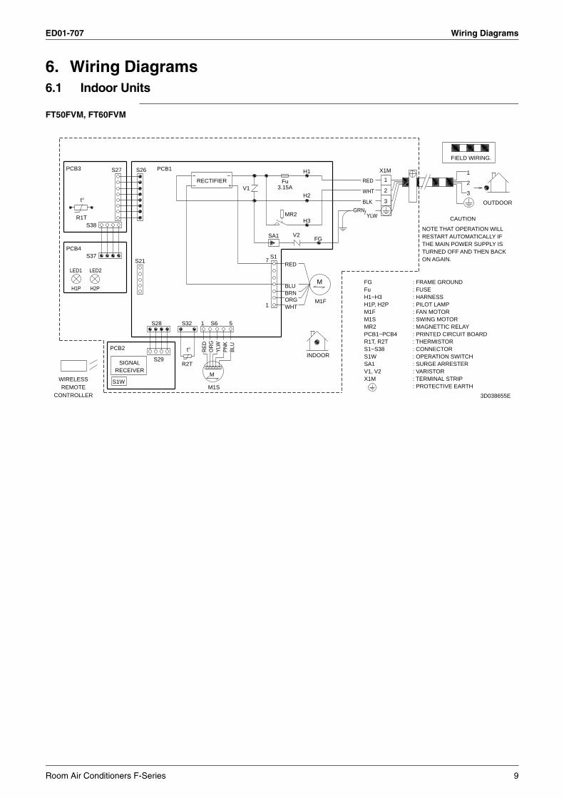
ED01-707 Wiring Diagrams
6. Wiring Diagrams6.1 Indoor Units
FT50FVM, FT60FVM
CONTROLLER
WIRELESS
REMOTE
PCB4
PCB3
LED1
H1P
R1T
t°
S37
S38
LED2
H2P
S27
PCB2
RECEIVER
S1W
SIGNAL
S21
S26
S29
S28
PCB1
R2T
S32
t°
~RECTIFIER
1
M1S
RE
D
M
S6
OR
GY
LW
~
PN
K
5
BLU
V1
7
1
SA1
S1
3.15AFu
MR2
WHT
BRN
RED
BLU
ORG
V2
H2
H3
H1
INDOOR
FG
M1F
M
GRN
WHT
BLK
/
RED
FG : FRAME GROUNDFu : FUSE H1~H3 : HARNESS H1P, H2P : PILOT LAMP M1F : FAN MOTOR
S1W : OPERATION SWITCH
MR2 : MAGNETTIC RELAY
SA1
M1S
PCB1~PCB4 : PRINTED CIRCUIT BOARDR1T, R2T : THERMISTORS1~S38 : CONNECTOR
YLW
V1, V2 : VARISTOR X1M : TERMINAL STRIP
X1M
3
2
1
: SWING MOTOR
: SURGE ARRESTER
: PROTECTIVE EARTH
NOTE THAT OPERATION WILLRESTART AUTOMATICALLY IFTHE MAIN POWER SUPPLY ISTURNED OFF AND THEN BACKON AGAIN.
FIELD WIRING.
CAUTION
2
3
1
OUTDOOR
3D038655E
Room Air Conditioners F-Series 9
Wiring Diagrams ED01-707
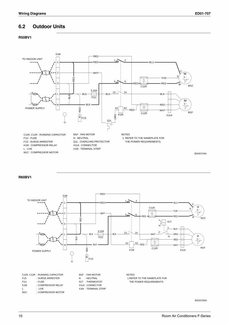
6.2 Outdoor Units
R50BV1
R60BV1
L : LIVE
C11R, C12R : RUNNING CAPACITOR
F1U : FUSE
F1S : SURGE ARRESTER
K1M : COMPRESSOR RELAY
M1C : COMPRESSOR MOTOR
TO INDOOR UNIT
POWER SUPPLY
X1M
N
L
3
2
1
BL
K
N : NEUTRAL
Q1L : OVERLOAD PROTECTOR
M1F : FAN MOTOR
X1M : TERMINAL STRIP
X11A : CONNECTOR
RE
D
RE
D
F1S
BLK
BLK
3.15A
F1U
WHT
RED
RED
BLK
Q1L
13
A1
5
1
OR
G K1M
NOTES
1. REFER TO THE NAMEPLATE FOR
A2
14
6
2
THE POWER REQUIREMENTS.
RED
RED
C12R
C11R
BLU
WHT
BLK
RED
YLW
RED
X11A
3D040743A
S
M
C
1~
1~
M
M
M1F
M1C
L
C11R, C12R
F1U
F1S
K1M
M1C
TO INDOOR UNIT
POWER SUPPLY
X1M
L
N
2
3
1
BLK
N
M1F
S1T
X1M
X11A
RE
D
RE
D
F1S
BLK
BLK
3.15A
F1U
WHT
RED
RED
BLK 13
A1
5
1
NOTES
1.REFER TO THE NAMEPLATE FOR
K1M
THE POWER REQUIREMENTS.
14
2
6
A2RED
RED
C11R
WHT
C12R
C
H
LS1T
L
H
YLW
WHT
RED
BLU
RED
BLK
ORG
X11A
S
C
R
1~
1~
3D032200A
M
M
M1F
M1C
: RUNNING CAPACITOR
: SURGE ARRESTER
: FUSE
: COMPRESSOR RELAY
: LIVE
: COMPRESSOR MOTOR
: FAN MOTOR
: NEUTRAL
: THERMOSTAT
: CONNECTOR
: TERMINAL STRIP
10 Room Air Conditioners F-Series
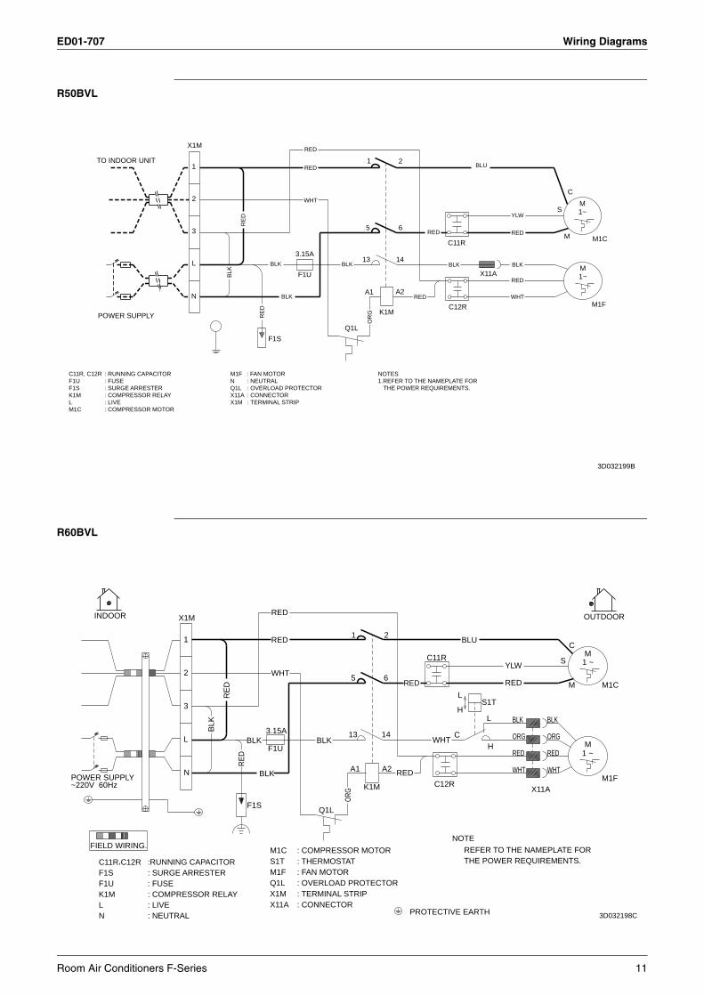
ED01-707 Wiring Diagrams
R50BVL
R60BVL
TO INDOOR UNIT
POWER SUPPLY
X1M
N
L
2
3
1
F1S
3.15A
F1U
Q1L
13
A1
5
1
K1M
A2
14
2
6
C12R
C11R
X11A
S
M
C
M1~
M1~
M1F
M1C
C11R, C12R : RUNNING CAPACITORF1U : FUSEF1S : SURGE ARRESTERK1M : COMPRESSOR RELAYL : LIVEM1C : COMPRESSOR MOTOR
M1F : FAN MOTORN : NEUTRALQ1L : OVERLOAD PROTECTORX11A : CONNECTORX1M : TERMINAL STRIP
NOTES1.REFER TO THE NAMEPLATE FOR
THE POWER REQUIREMENTS.
RED
RED
BLK
BLU
YLW
BLK
WHT
RED
RED
BL
K
RE
D
RE
DBLK
BLK
WHT
RED
RED
BLK
OR
G
3D032199B
POWER SUPPLY~220V 60Hz
FIELD WIRING.
INDOOR
LN
F1S
K1MF1U
C11R,C12R
: FUSE
: LIVE: COMPRESSOR RELAY
: SURGE ARRESTER:RUNNING CAPACITOR
: NEUTRAL
X1M
2
3
N
L
1
BLK
RE
D
RE
D
BLK
F1S
BLK
3.15A
X1M
M1FQ1L
S1T
F1U
X11A
M1C
WHT
RED
RED
: CONNECTOR
: FAN MOTOR
: TERMINAL STRIP
: COMPRESSOR MOTOR: THERMOSTAT
: OVERLOAD PROTECTOR
BLK
Q1L
13
A1
ORG
5
1
K1M
14
2
6
A2
PROTECTIVE EARTH
RED
RED
C11R
WHT
C12R
NOTE
C
H
L
BLU
THE POWER REQUIREMENTS.REFER TO THE NAMEPLATE FOR
S1T
L
H
YLW
BLK
WHT
RED
ORG
RED
X11A
BLK
WHT
ORG
RED
S
C
M
1 ~
1 ~M
M
OUTDOOR
M1F
M1C
3D032198C
Room Air Conditioners F-Series 11
Piping Diagrams ED01-707
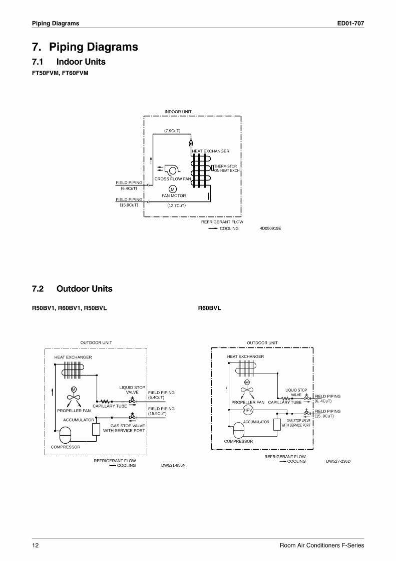
7. Piping Diagrams7.1 Indoor UnitsFT50FVM, FT60FVM
7.2 Outdoor Units
R50BV1, R60BV1, R50BVL R60BVL
(15.9CuT)
FIELD PIPING
FIELD PIPING
(6.4CuT)
CROSS FLOW FAN
FAN MOTOR
(7.9CuT)
INDOOR UNIT
(12.7CuT)
M
HEAT EXCHANGER
REFRIGERANT FLOW
ON HEAT EXCH.THERMISTOR
COOLING 4D050919E
OUTDOOR UNIT
COMPRESSOR
PROPELLER FAN
HEAT EXCHANGER
ACCUMULATOR
M
CAPILLARY TUBE
REFRIGERANT FLOWCOOLING
GAS STOP VALVEWITH SERVICE PORT
LIQUID STOPVALVE
FIELD PIPING(15.9CuT)
FIELD PIPING(6.4CuT)
DW521-856N
OUTDOOR UNIT
COMPRESSOR
HEAT EXCHANGER
PROPELLER FAN
HPV
ACCUMULATOR
CAPILLARY TUBE
REFRIGERANT FLOWCOOLING
GAS STOP VALVEWITH SERVICE PORT
LIQUID STOPVALVE FIELD PIPING
(6. 4CuT)
FIELD PIPING(15. 9CuT)
DW527-236D
M
12 Room Air Conditioners F-Series
ED01-707 Capacity Tables
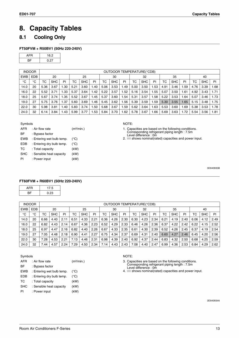
8. Capacity Tables8.1 Cooling Only
FT50FVM + R50BV1 (50Hz 220-240V)
3D040933B
FT60FVM + R60BV1 (50Hz 220-240V)
3D040934A
AFR 16.2
BF 0.27
INDOOR OUTDOOR TEMPERATURE(°CDB)
EWB EDB 20 25 30 32 35 40
°C °C TC SHC PI TC SHC PI TC SHC PI TC SHC PI TC SHC PI TC SHC PI
14.0 20 5.36 3.67 1.30 5.21 3.60 1.40 5.06 3.53 1.49 5.00 3.50 1.53 4.91 3.46 1.59 4.76 3.39 1.68
16.0 22 5.52 3.71 1.33 5.37 3.64 1.42 5.22 3.57 1.52 5.16 3.54 1.55 5.07 3.50 1.61 4.92 3.43 1.71
18.0 25 5.67 3.74 1.35 5.52 3.67 1.45 5.37 3.60 1.54 5.31 3.57 1.58 5.22 3.53 1.64 5.07 3.46 1.73
19.0 27 5.75 3.76 1.37 5.60 3.69 1.46 5.45 3.62 1.56 5.39 3.59 1.59 5.30 3.55 1.65 5.15 3.48 1.75
22.0 30 5.98 3.81 1.40 5.83 3.74 1.50 5.68 3.67 1.59 5.62 3.64 1.63 5.53 3.60 1.69 5.38 3.53 1.78
24.0 32 6.14 3.84 1.43 5.99 3.77 1.53 5.84 3.70 1.62 5.78 3.67 1.66 5.69 3.63 1.72 5.54 3.56 1.81
Symbols NOTE:
AFR : Air flow rate (m³/min.) 1. Capacities are based on the following conditions.Corresponding refrigerant piping length : 7.5mLevel difference : 0m
2. shows nominal(rated) capacities and power input.BF : Bypass factor
EWB : Entering wet bulb temp. (°C)
EDB : Entering dry bulb temp. (°C)
TC : Total capacity (kW)
SHC : Sensible heat capacity (kW)
PI : Power input (kW)
AFR 17.5
BF 0.23
INDOOR OUTDOOR TEMPERATURE(°CDB)
EWB EDB 20 25 30 32 35 40
°C °C TC SHC PI TC SHC PI TC SHC PI TC SHC PI TC SHC PI TC SHC PI
14.0 20 6.66 4.40 2.11 6.51 4.33 2.21 6.36 4.26 2.30 6.30 4.23 2.34 6.21 4.19 2.40 6.06 4.12 2.49
16.0 22 6.82 4.43 2.14 6.67 4.36 2.23 6.52 4.29 2.33 6.46 4.26 2.36 6.37 4.22 2.42 6.22 4.15 2.52
18.0 25 6.97 4.47 2.16 6.82 4.40 2.26 6.67 4.33 2.35 6.61 4.30 2.39 6.52 4.26 2.45 6.37 4.19 2.54
19.0 27 7.05 4.48 2.18 6.90 4.41 2.27 6.75 4.34 2.37 6.69 4.31 2.40 6.60 4.27 2.46 6.45 4.20 2.56
22.0 30 7.28 4.53 2.21 7.13 4.46 2.31 6.98 4.39 2.40 6.92 4.37 2.44 6.83 4.32 2.50 6.68 4.25 2.59
24.0 32 7.44 4.57 2.24 7.29 4.50 2.34 7.14 4.43 2.43 7.08 4.40 2.47 6.99 4.36 2.53 6.84 4.29 2.62
Symbols NOTE:
AFR : Air flow rate (m³/min.) 3. Capacities are based on the following conditions.Corresponding refrigerant piping length : 7.5mLevel difference : 0m
4. shows nominal(rated) capacities and power input.BF : Bypass factor
EWB : Entering wet bulb temp. (°C)
EDB : Entering dry bulb temp. (°C)
TC : Total capacity (kW)
SHC : Sensible heat capacity (kW)
PI : Power input (kW)
Room Air Conditioners F-Series 13
Capacity Tables ED01-707
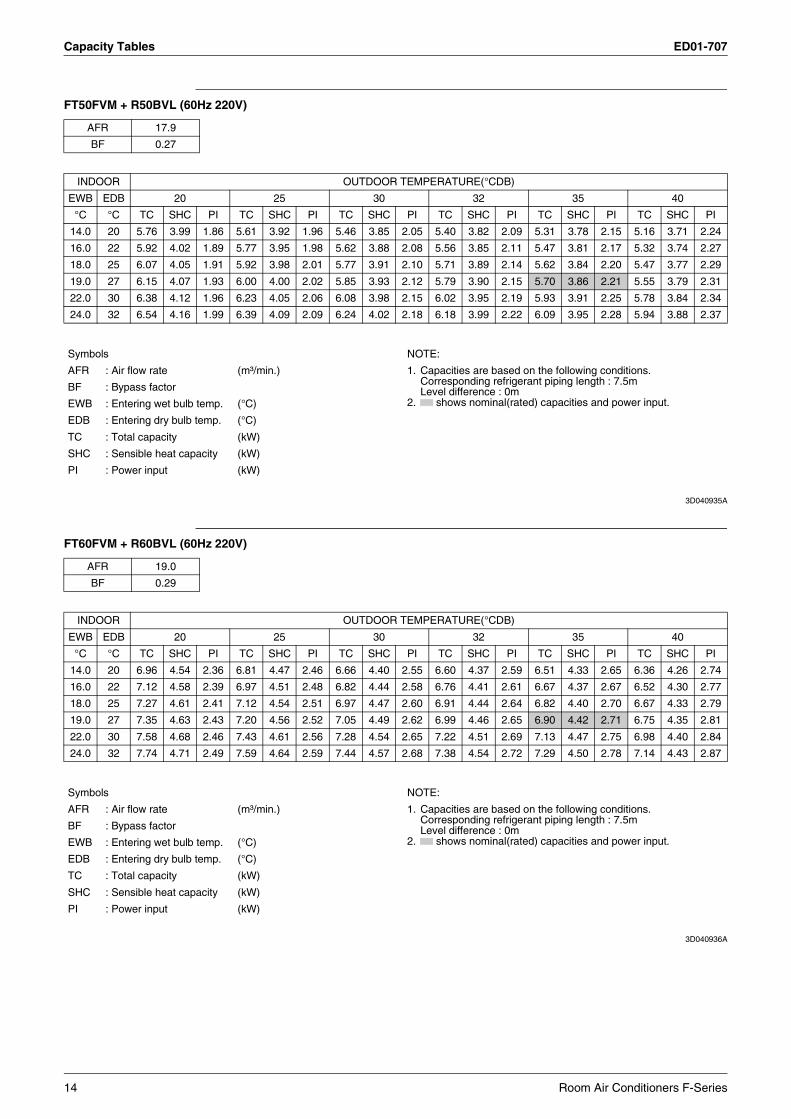
FT50FVM + R50BVL (60Hz 220V)
3D040935A
FT60FVM + R60BVL (60Hz 220V)
3D040936A
AFR 17.9
BF 0.27
INDOOR OUTDOOR TEMPERATURE(°CDB)
EWB EDB 20 25 30 32 35 40
°C °C TC SHC PI TC SHC PI TC SHC PI TC SHC PI TC SHC PI TC SHC PI
14.0 20 5.76 3.99 1.86 5.61 3.92 1.96 5.46 3.85 2.05 5.40 3.82 2.09 5.31 3.78 2.15 5.16 3.71 2.24
16.0 22 5.92 4.02 1.89 5.77 3.95 1.98 5.62 3.88 2.08 5.56 3.85 2.11 5.47 3.81 2.17 5.32 3.74 2.27
18.0 25 6.07 4.05 1.91 5.92 3.98 2.01 5.77 3.91 2.10 5.71 3.89 2.14 5.62 3.84 2.20 5.47 3.77 2.29
19.0 27 6.15 4.07 1.93 6.00 4.00 2.02 5.85 3.93 2.12 5.79 3.90 2.15 5.70 3.86 2.21 5.55 3.79 2.31
22.0 30 6.38 4.12 1.96 6.23 4.05 2.06 6.08 3.98 2.15 6.02 3.95 2.19 5.93 3.91 2.25 5.78 3.84 2.34
24.0 32 6.54 4.16 1.99 6.39 4.09 2.09 6.24 4.02 2.18 6.18 3.99 2.22 6.09 3.95 2.28 5.94 3.88 2.37
Symbols NOTE:
AFR : Air flow rate (m³/min.) 1. Capacities are based on the following conditions.Corresponding refrigerant piping length : 7.5mLevel difference : 0m
2. shows nominal(rated) capacities and power input.BF : Bypass factor
EWB : Entering wet bulb temp. (°C)
EDB : Entering dry bulb temp. (°C)
TC : Total capacity (kW)
SHC : Sensible heat capacity (kW)
PI : Power input (kW)
AFR 19.0
BF 0.29
INDOOR OUTDOOR TEMPERATURE(°CDB)
EWB EDB 20 25 30 32 35 40
°C °C TC SHC PI TC SHC PI TC SHC PI TC SHC PI TC SHC PI TC SHC PI
14.0 20 6.96 4.54 2.36 6.81 4.47 2.46 6.66 4.40 2.55 6.60 4.37 2.59 6.51 4.33 2.65 6.36 4.26 2.74
16.0 22 7.12 4.58 2.39 6.97 4.51 2.48 6.82 4.44 2.58 6.76 4.41 2.61 6.67 4.37 2.67 6.52 4.30 2.77
18.0 25 7.27 4.61 2.41 7.12 4.54 2.51 6.97 4.47 2.60 6.91 4.44 2.64 6.82 4.40 2.70 6.67 4.33 2.79
19.0 27 7.35 4.63 2.43 7.20 4.56 2.52 7.05 4.49 2.62 6.99 4.46 2.65 6.90 4.42 2.71 6.75 4.35 2.81
22.0 30 7.58 4.68 2.46 7.43 4.61 2.56 7.28 4.54 2.65 7.22 4.51 2.69 7.13 4.47 2.75 6.98 4.40 2.84
24.0 32 7.74 4.71 2.49 7.59 4.64 2.59 7.44 4.57 2.68 7.38 4.54 2.72 7.29 4.50 2.78 7.14 4.43 2.87
Symbols NOTE:
AFR : Air flow rate (m³/min.) 1. Capacities are based on the following conditions.Corresponding refrigerant piping length : 7.5mLevel difference : 0m
2. shows nominal(rated) capacities and power input.BF : Bypass factor
EWB : Entering wet bulb temp. (°C)
EDB : Entering dry bulb temp. (°C)
TC : Total capacity (kW)
SHC : Sensible heat capacity (kW)
PI : Power input (kW)
14 Room Air Conditioners F-Series
ED01-707 Capacity Tables
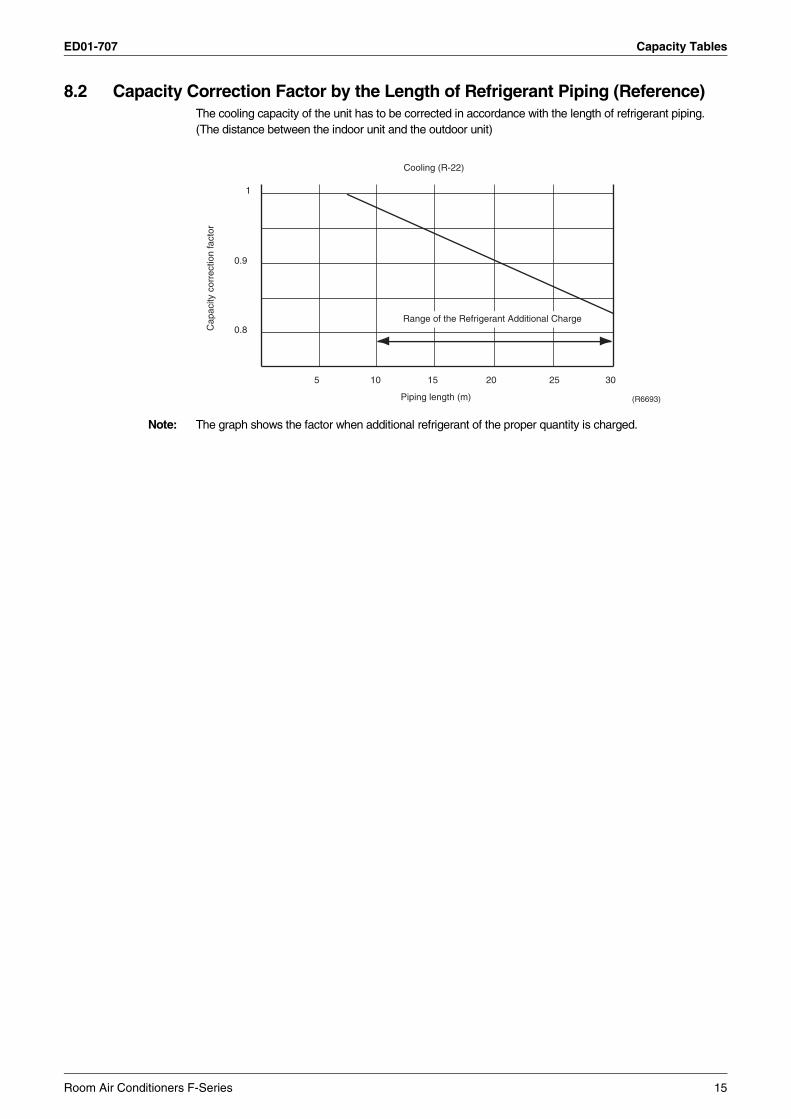
8.2 Capacity Correction Factor by the Length of Refrigerant Piping (Reference)The cooling capacity of the unit has to be corrected in accordance with the length of refrigerant piping. (The distance between the indoor unit and the outdoor unit)
Note: The graph shows the factor when additional refrigerant of the proper quantity is charged.
Cap
acity
cor
rect
ion
fact
or
1
5 10 15 20 3025
0.9
0.8
Cooling (R-22)
Piping length (m) (R6693)
Range of the Refrigerant Additional Charge
Room Air Conditioners F-Series 15
Operation Limit ED01-707
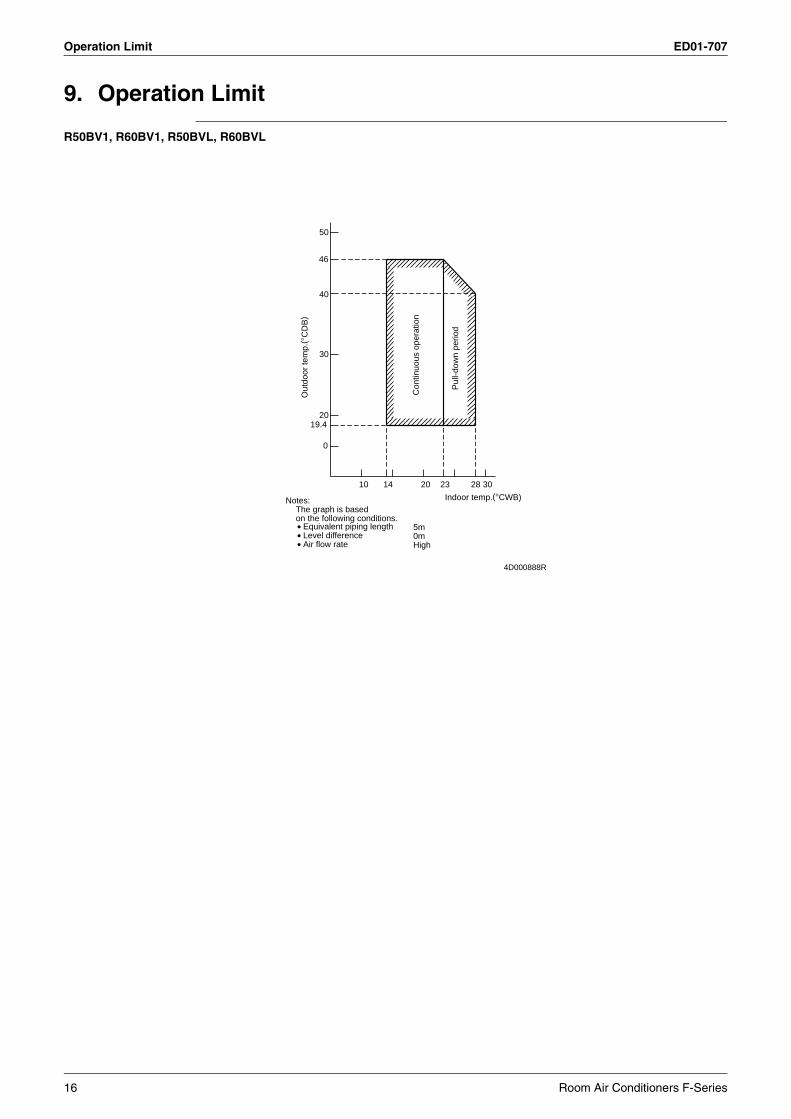
9. Operation Limit
R50BV1, R60BV1, R50BVL, R60BVL
Notes:
• Equivalent piping length• Level difference• Air flow rate
on the following conditions.The graph is based
Ou
tdo
or
tem
p.(
° CD
B)
19.4
46
50
40
30
20
0
10 14
Co
ntin
uo
us
op
era
tion
20
5m
23
0mHigh
Indoor temp.(°CWB)
Pu
ll-d
ow
n p
erio
d
28 30
4D000888R
16 Room Air Conditioners F-Series
ED01-707 Sound Level
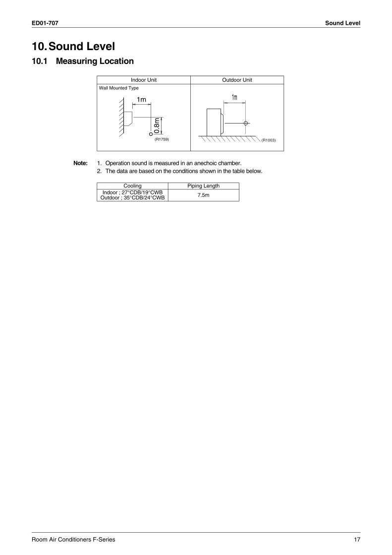
10.Sound Level10.1 Measuring Location
Note: 1. Operation sound is measured in an anechoic chamber.2. The data are based on the conditions shown in the table below.
Indoor Unit Outdoor Unit
Wall Mounted Type
1m
0.8m
(R1759)
1m
(R1003)
Cooling Piping LengthIndoor ; 27°CDB/19°CWB
Outdoor ; 35°CDB/24°CWB 7.5m
Room Air Conditioners F-Series 17
Sound Level ED01-707
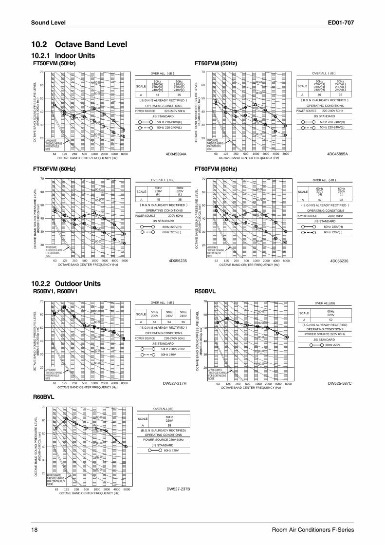
10.2 Octave Band Level10.2.1 Indoor Units
10.2.2 Outdoor Units
FT50FVM (50Hz) FT60FVM (50Hz)
FT50FVM (60Hz) FT60FVM (60Hz)
NC-40
43
240V(L)
220V(H)50Hz
NC-30 50Hz 220-240V(H)
50Hz 220-240V(L)
230V(L)230V(H)
50Hz
240V(H)
35
220-240V 50Hz
NC-20
NC-60
NC-50
220V(L)
POWER SOURCE
JIS STANDARD
OPERATING CONDITIONS
OC
TAV
E B
AN
D S
OU
ND
PR
ES
SU
RE
LE
VE
Ld
B( 0
dB
=0
.00
02
µ b
ar)
70
60
20
30
50
40
THRESHOLD HEARINGAPPROXIMATE
FOR CONTINUOUSNOISE
63 125OCTAVE BAND CENTER FREQUENCY (Hz)
250 500 1000 2000 4000 8000
OVER ALL ( dB )
SCALE
A
( B.G.N IS ALREADY RECTIFIED )
4D045894A
NC-50
220V(L)230V(L)240V(L)
NC-20
50Hz 220-240V(H)NC-30
50Hz 220-240V(L)
36
NC-60
220-240V 50HzNC-40
220V(H)230V(H)240V(H)
50Hz 50Hz
46
POWER SOURCE
JIS STANDARD
OPERATING CONDITIONS
OC
TAV
E B
AN
D S
OU
ND
PR
ES
SU
RE
LE
VE
Ld
B( 0
dB
=0
.00
02
µ b
ar)
70
60
20
30
50
40
THRESHOLD HEARINGAPPROXIMATE
FOR CONTINUOUSNOISE
63 125OCTAVE BAND CENTER FREQUENCY (Hz)
250 500 1000 2000 4000 8000
OVER ALL ( dB )
SCALE
A
( B.G.N IS ALREADY RECTIFIED )
4D045895A
(L)
60Hz
60Hz 220V(L)
NC-50
NC-20
60Hz
(H)
35
NC-60
NC-30
45
60Hz 220V(H)
NC-40 220V 60Hz
220V 220V
POWER SOURCE
JIS STANDARD
OPERATING CONDITIONS
OC
TAV
E B
AN
D S
OU
ND
PR
ES
SU
RE
LE
VE
Ld
B( 0
dB
=0
.00
02
µ b
ar)
70
60
20
30
50
40
THRESHOLD HEARINGAPPROXIMATE
FOR CONTINUOUSNOISE
63 125OCTAVE BAND CENTER FREQUENCY (Hz)
250 500 1000 2000 4000 8000
OVER ALL ( dB )
SCALE
A
( B.G.N IS ALREADY RECTIFIED )
4D056235
NC-60220V
(L)
60Hz
36
220V 60Hz
47
220V
60Hz 220V(L)
60Hz 220V(H)
60Hz
NC-50
NC-20
NC-30
(H)
NC-40 POWER SOURCE
JIS STANDARD
OPERATING CONDITIONS
OC
TAV
E B
AN
D S
OU
ND
PR
ES
SU
RE
LE
VE
Ld
B( 0
dB
=0
.00
02
µ b
ar)
70
60
20
30
50
40
THRESHOLD HEARINGAPPROXIMATE
FOR CONTINUOUSNOISE
63 125OCTAVE BAND CENTER FREQUENCY (Hz)
250 500 1000 2000 4000 8000
OVER ALL ( dB )
SCALE
A
( B.G.N IS ALREADY RECTIFIED )
4D056236
R50BV1, R60BV1 R50BVL
R60BVL
NC-40
NC-30
NC-50
NC-60
NC-20
50Hz220V
54
50Hz230V
54
50Hz240V
55
50Hz 240V
50Hz 220V• 230V
POWER SOURCE
JIS STANDARD
OPERATING CONDITIONS
OC
TAV
E B
AN
D S
OU
ND
PR
ES
SU
RE
LE
VE
Ld
B( 0
dB
=0
.00
02
µ b
ar)
70
60
20
30
50
40
THRESHOLD HEARINGAPPROXIMATE
FOR CONTINUOUSNOISE
63 125OCTAVE BAND CENTER FREQUENCY (Hz)
250 500 1000 2000 4000 8000
OVER ALL ( dB )
SCALE
A
( B.G.N IS ALREADY RECTIFIED )
220-240V 50Hz
DW527-217H
NC-40
NC-30
NC-50
NC-60
NC-20
DW525-587C
OC
TAV
E B
AN
D S
OU
ND
PR
ES
SU
RE
LE
VE
Ld
B(0
dB
=0
.00
02
µ b
ar)
OCTAVE BAND CENTER FREQUENCY (Hz)
APPROXIMATETHRESHOLD HEARINGFOR CONTINUOUSNOISE
63 125 250 500 1000 2000 4000 8000
70
60
20
30
50
40
SCALE
A
60Hz220V
52
OPERATING CONDITIONS
POWER SOURCE 220V 60Hz
OVER ALL(dB)
(B.G.N IS ALREADY RECTIFIED)
JIS STANDARD
60Hz 220V
NC-40
NC-30
NC-50
NC-60
NC-20
DW527-237B
OC
TAV
E B
AN
D S
OU
ND
PR
ES
SU
RE
LE
VE
Ld
B(0
dB
=0
.00
02
µ b
ar)
OCTAVE BAND CENTER FREQUENCY (Hz)
APPROXIMATETHRESHOLD HEARINGFOR CONTINUOUSNOISE
63 125 250 500 1000 2000 4000 8000
70
60
20
30
50
40
SCALE
A
60Hz220V
55
OPERATING CONDITIONS
POWER SOURCE 220V 60Hz
OVER ALL(dB)
(B.G.N IS ALREADY RECTIFIED)
JIS STANDARD
60Hz 220V
18 Room Air Conditioners F-Series
ED01-707 Electric Characteristics
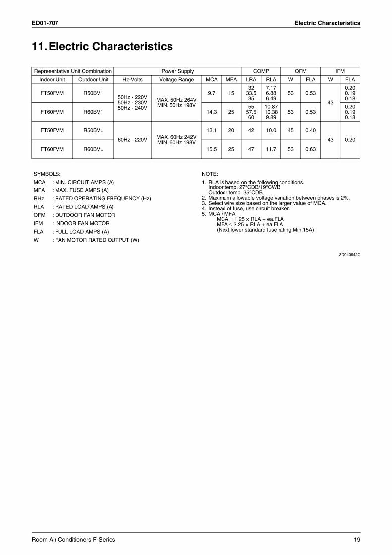
11.Electric Characteristics
3D040942C
Representative Unit Combination Power Supply COMP OFM IFM
Indoor Unit Outdoor Unit Hz-Volts Voltage Range MCA MFA LRA RLA W FLA W FLA
FT50FVM R50BV150Hz - 220V50Hz - 230V50Hz - 240V
MAX. 50Hz 264VMIN. 50Hz 198V
9.7 1532
33.535
7.176.886.49
53 0.53
43
0.200.190.18
FT60FVM R60BV1 14.3 2555
57.560
10.8710.389.89
53 0.530.200.190.18
FT50FVM R50BVL
60Hz - 220V MAX. 60Hz 242VMIN. 60Hz 198V
13.1 20 42 10.0 45 0.40
43 0.20
FT60FVM R60BVL 15.5 25 47 11.7 53 0.63
SYMBOLS: NOTE:
MCA : MIN. CIRCUIT AMPS (A) 1. RLA is based on the following conditions.Indoor temp. 27°CDB/19°CWBOutdoor temp. 35°CDB.
2. Maximum allowable voltage variation between phases is 2%.3. Select wire size based on the larger value of MCA.4. Instead of fuse, use circuit breaker.5. MCA / MFA
MCA = 1.25 × RLA + ea.FLAMFA ≤ 2.25 × RLA + ea.FLA(Next lower standard fuse rating.Min.15A)
MFA : MAX. FUSE AMPS (A)
RHz : RATED OPERATING FREQUENCY (Hz)
RLA : RATED LOAD AMPS (A)
OFM : OUTDOOR FAN MOTOR
IFM : INDOOR FAN MOTOR
FLA : FULL LOAD AMPS (A)
W : FAN MOTOR RATED OUTPUT (W)
Room Air Conditioners F-Series 19
Installation Manual ED01-707
12. Installation Manual
Safety Precautions
CAUTION
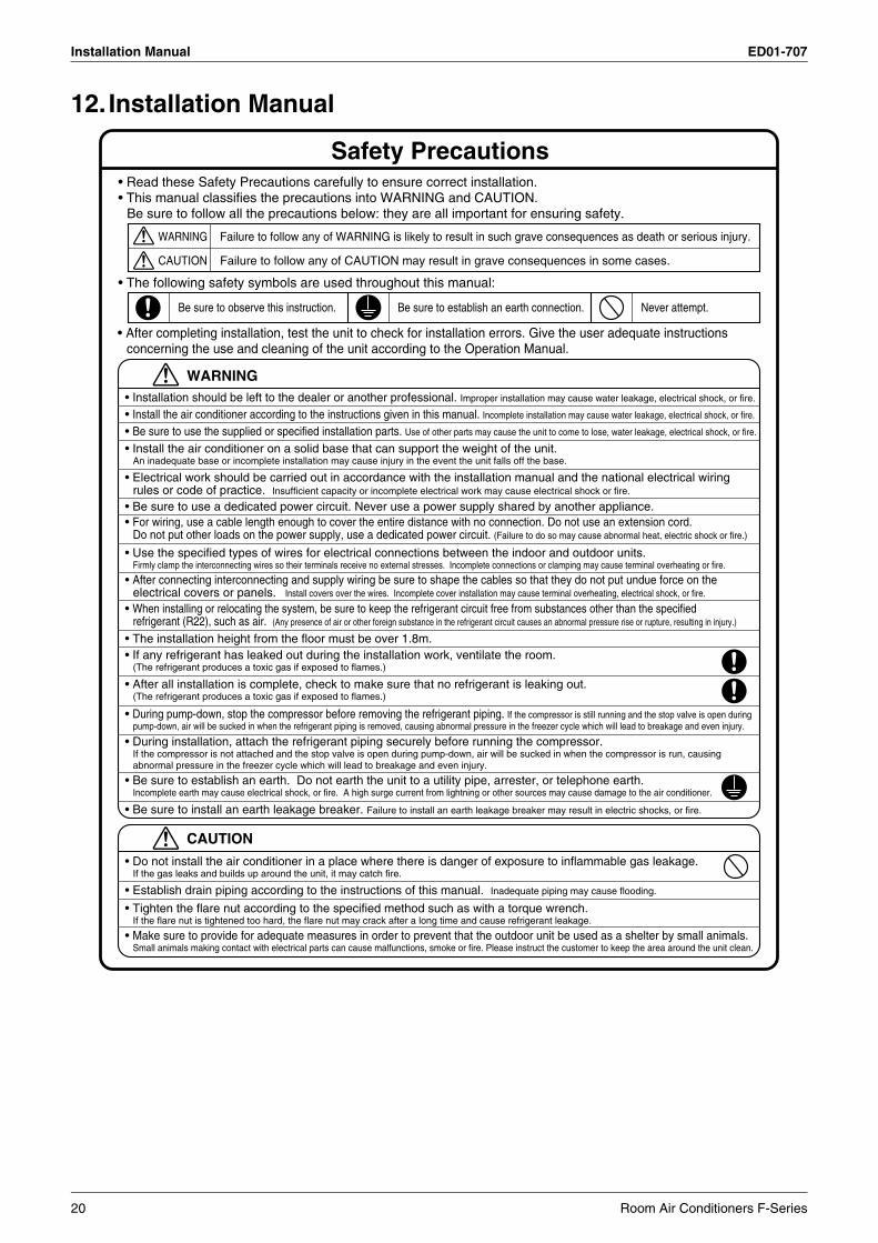
• Do not install the air conditioner in a place where there is danger of exposure to inflammable gas leakage. If the gas leaks and builds up around the unit, it may catch fire.
• Establish drain piping according to the instructions of this manual. Inadequate piping may cause flooding.
• Tighten the flare nut according to the specified method such as with a torque wrench. If the flare nut is tightened too hard, the flare nut may crack after a long time and cause refrigerant leakage.
• Make sure to provide for adequate measures in order to prevent that the outdoor unit be used as a shelter by small animals.Small animals making contact with electrical parts can cause malfunctions, smoke or fire. Please instruct the customer to keep the area around the unit clean.
• Read these Safety Precautions carefully to ensure correct installation.• This manual classifies the precautions into WARNING and CAUTION.
Be sure to follow all the precautions below: they are all important for ensuring safety.
WARNING
WARNING
CAUTION
Failure to follow any of WARNING is likely to result in such grave consequences as death or serious injury.
Failure to follow any of CAUTION may result in grave consequences in some cases.
• The following safety symbols are used throughout this manual:
Be sure to observe this instruction. Be sure to establish an earth connection. Never attempt.
• After completing installation, test the unit to check for installation errors. Give the user adequate instructions concerning the use and cleaning of the unit according to the Operation Manual.
• Installation should be left to the dealer or another professional. Improper installation may cause water leakage, electrical shock, or fire.
• Install the air conditioner according to the instructions given in this manual. Incomplete installation may cause water leakage, electrical shock, or fire.
• Be sure to use the supplied or specified installation parts. Use of other parts may cause the unit to come to lose, water leakage, electrical shock, or fire.
• Install the air conditioner on a solid base that can support the weight of the unit. An inadequate base or incomplete installation may cause injury in the event the unit falls off the base.
• Electrical work should be carried out in accordance with the installation manual and the national electrical wiring rules or code of practice. Insufficient capacity or incomplete electrical work may cause electrical shock or fire.
• Be sure to use a dedicated power circuit. Never use a power supply shared by another appliance.
• Use the specified types of wires for electrical connections between the indoor and outdoor units. Firmly clamp the interconnecting wires so their terminals receive no external stresses. Incomplete connections or clamping may cause terminal overheating or fire.
• For wiring, use a cable length enough to cover the entire distance with no connection. Do not use an extension cord. Do not put other loads on the power supply, use a dedicated power circuit. (Failure to do so may cause abnormal heat, electric shock or fire.)
• After all installation is complete, check to make sure that no refrigerant is leaking out. (The refrigerant produces a toxic gas if exposed to flames.)
• After connecting interconnecting and supply wiring be sure to shape the cables so that they do not put undue force on the electrical covers or panels. Install covers over the wires. Incomplete cover installation may cause terminal overheating, electrical shock, or fire.
• When installing or relocating the system, be sure to keep the refrigerant circuit free from substances other than the specified refrigerant (R22), such as air. (Any presence of air or other foreign substance in the refrigerant circuit causes an abnormal pressure rise or rupture, resulting in injury.)
• If any refrigerant has leaked out during the installation work, ventilate the room. (The refrigerant produces a toxic gas if exposed to flames.)
• The installation height from the floor must be over 1.8m.
• Be sure to establish an earth. Do not earth the unit to a utility pipe, arrester, or telephone earth. Incomplete earth may cause electrical shock, or fire. A high surge current from lightning or other sources may cause damage to the air conditioner.
• Be sure to install an earth leakage breaker. Failure to install an earth leakage breaker may result in electric shocks, or fire.
• During pump-down, stop the compressor before removing the refrigerant piping. If the compressor is still running and the stop valve is open during pump-down, air will be sucked in when the refrigerant piping is removed, causing abnormal pressure in the freezer cycle which will lead to breakage and even injury.
• During installation, attach the refrigerant piping securely before running the compressor.If the compressor is not attached and the stop valve is open during pump-down, air will be sucked in when the compressor is run, causing abnormal pressure in the freezer cycle which will lead to breakage and even injury.
20 Room Air Conditioners F-Series
ED01-707 Installation Manual
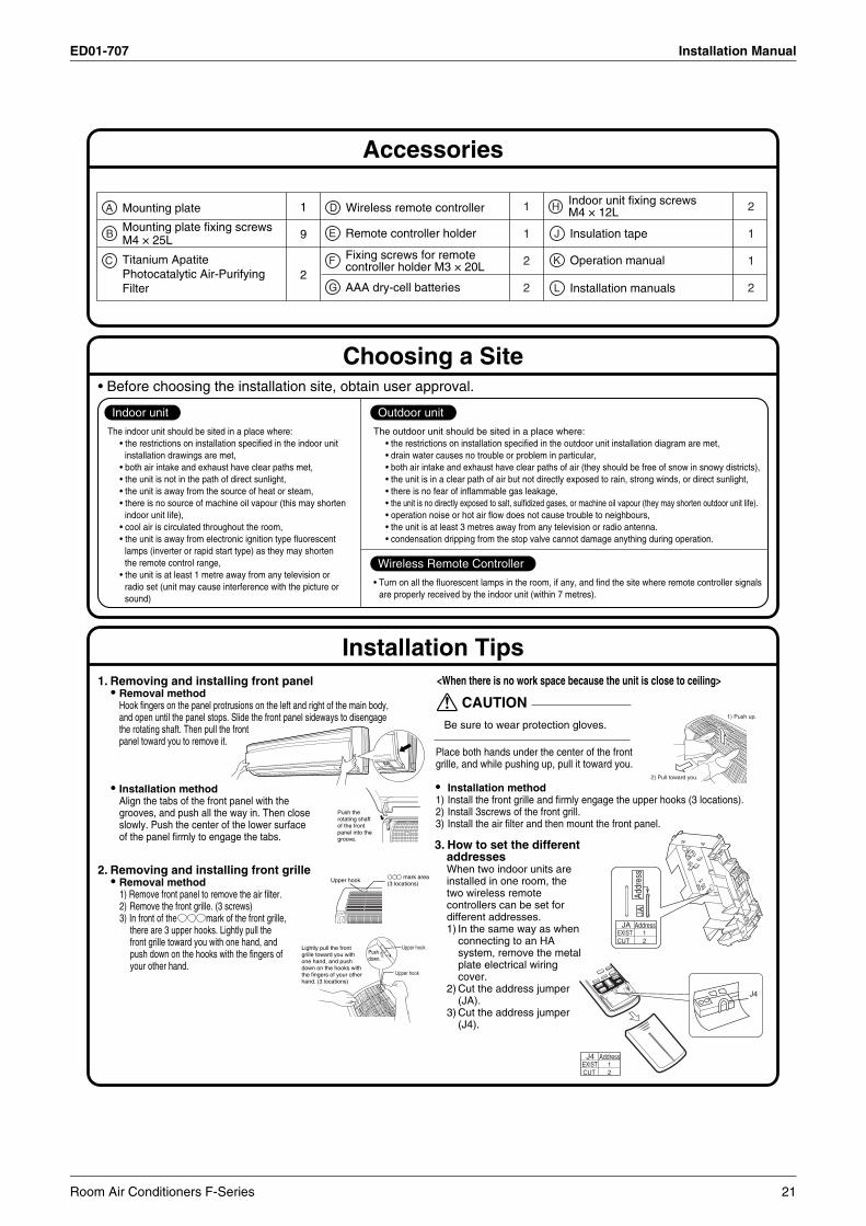
Choosing a Site
The indoor unit should be sited in a place where:• the restrictions on installation specified in the indoor unit
installation drawings are met,• both air intake and exhaust have clear paths met,• the unit is not in the path of direct sunlight,• the unit is away from the source of heat or steam,• there is no source of machine oil vapour (this may shorten
indoor unit life),• cool air is circulated throughout the room,• the unit is away from electronic ignition type fluorescent
lamps (inverter or rapid start type) as they may shorten the remote control range,
• the unit is at least 1 metre away from any television or radio set (unit may cause interference with the picture or sound)
• Before choosing the installation site, obtain user approval.
Indoor unit
The outdoor unit should be sited in a place where:• the restrictions on installation specified in the outdoor unit installation diagram are met,• drain water causes no trouble or problem in particular,• both air intake and exhaust have clear paths of air (they should be free of snow in snowy districts),• the unit is in a clear path of air but not directly exposed to rain, strong winds, or direct sunlight,• there is no fear of inflammable gas leakage,• the unit is no directly exposed to salt, sulfidized gases, or machine oil vapour (they may shorten outdoor unit life).• operation noise or hot air flow does not cause trouble to neighbours,• the unit is at least 3 metres away from any television or radio antenna.• condensation dripping from the stop valve cannot damage anything during operation.
Outdoor unit
• Turn on all the fluorescent lamps in the room, if any, and find the site where remote controller signals are properly received by the indoor unit (within 7 metres).
Wireless Remote Controller
Accessories
Installation Tips1. Removing and installing front panel
• Removal methodHook fingers on the panel protrusions on the left and right of the main body, and open until the panel stops. Slide the front panel sideways to disengagethe rotating shaft. Then pull the front panel toward you to remove it.
• Installation methodAlign the tabs of the front panel with the grooves, and push all the way in. Then close slowly. Push the center of the lower surface of the panel firmly to engage the tabs.
Push the rotating shaft of the front panel into the groove.
2. Removing and installing front grille• Removal method
1) Remove front panel to remove the air filter.2) Remove the front grille. (3 screws)3) In front of the mark of the front grille,
there are 3 upper hooks. Lightly pull the front grille toward you with one hand, and push down on the hooks with the fingers of your other hand.
Lightly pull the front grille toward you with one hand, and push down on the hooks with the fingers of your other hand. (3 locations)
Pushdown.
Upper hook
Upper hook
<When there is no work space because the unit is close to ceiling>
Be sure to wear protection gloves.
CAUTION1) Push up.
2) Pull toward you.
Place both hands under the center of the front grille, and while pushing up, pull it toward you.
• Installation method1) Install the front grille and firmly engage the upper hooks (3 locations).2) Install 3screws of the front grill.3) Install the air filter and then mount the front panel.
3. How to set the different addressesWhen two indoor units are installed in one room, the two wireless remote controllers can be set for different addresses.1) In the same way as when
connecting to an HA system, remove the metal plate electrical wiring cover.
2) Cut the address jumper (JA).
3) Cut the address jumper (J4).
Addr
ess
JA
AddressJAEXIST 1CUT 2
J4
AddressJ4EXIST 1 CUT 2
A Mounting plate
E Remote controller holder
F Fixing screws for remote controller holder M3 × 20L
H Indoor unit fixing screwsM4 × 12L
G AAA dry-cell batteries
J Insulation tape
K Operation manual
L Installation manuals
1
9
2
1
1
2
2
2
1
1
2
D Wireless remote controller
C Titanium Apatite Photocatalytic Air-Purifying Filter
BMounting plate fixing screwsM4 × 25L
mark area (3 locations)
Upper hook
Room Air Conditioners F-Series 21
Installation Manual ED01-707
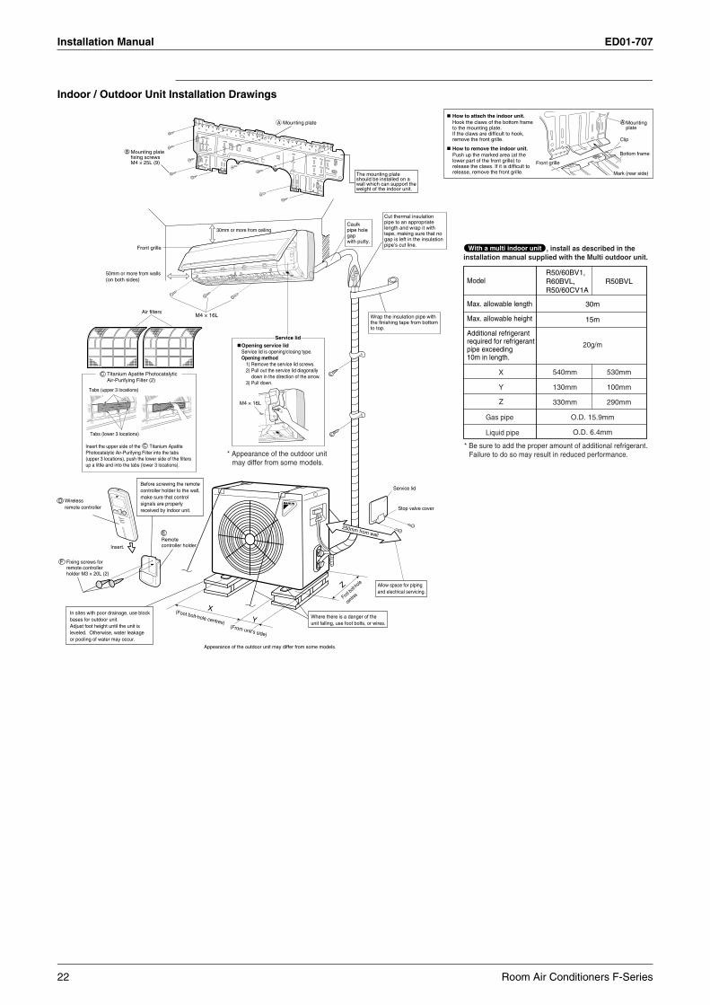
Indoor / Outdoor Unit Installation Drawings
Foot bolt-h
ole
centres
(Foot bolt-hole centres)
X
Z
Y(From unit’s side)
In sites with poor drainage, use block bases for outdoor unit. Adjust foot height until the unit is leveled. Otherwise, water leakage or pooling of water may occur.
Where there is a danger of the unit falling, use foot bolts, or wires.
Service lid
Stop valve cover
Allow space for piping and electrical servicing.
* Be sure to add the proper amount of additional refrigerant. Failure to do so may result in reduced performance.* Appearance of the outdoor unit
may differ from some models.
250mm from wallE
D
F
Wrap the insulation pipe with the finishing tape from bottom to top.
Cut thermal insulation pipe to an appropriate length and wrap it with tape, making sure that no gap is left in the insulation pipe’s cut line.
Caulk pipe hole gap with putty.
30mm or more from ceiling
Front grille
50mm or more from walls (on both sides)
Mounting plate fixing screws M4 × 25L (9)
The mounting plate should be installed on a wall which can support the weight of the indoor unit.
A Mounting plate
B
Service lid
Wireless remote controller
Fixing screws for remote controller holder M3 × 20L (2)
Before screwing the remote controller holder to the wall, make sure that control signals are properly received by indoor unit.
Remote controller holderInsert.
Model
Max. allowable length
Max. allowable height
Additional refrigerant required for refrigerantpipe exceeding 10m in length.
30m
15m
Gas pipe
Liquid pipe
O.D. 15.9mm
O.D. 6.4mm
20g/m
X
Y
Z
R50/60BV1, R60BVL, R50/60CV1A
540mm
130mm
330mm
R50BVL
530mm
100mm
290mm
How to attach the indoor unit.Hook the claws of the bottom frameto the mounting plate.If the claws are difficult to hook,remove the front grille.
How to remove the indoor unit.Push up the marked area (at thelower part of the front grille) torelease the claws. If it is difficult torelease, remove the front grille.
Front grille
A Mountingplate
Clip
Bottom frame
Mark (rear side)
M4 × 16L
C Titanium Apatite Photocatalytic Air-Purifying Filter (2)
Tabs (upper 3 locations)
Tabs (lower 3 locations)
Air filters
Insert the upper side of the Titanium Apatite Photocatalytic Air-Purifying Filter into the tabs (upper 3 locations), push the lower side of the filters up a little and into the tabs (lower 3 locations).
C
M4 × 16L
Opening service lidService lid is opening/closing type.Opening method
1) Remove the service lid screws.2) Pull out the service lid diagonally
down in the direction of the arrow.3) Pull down.
, install as described in the installation manual supplied with the Multi outdoor unit.
With a multi indoor unit
Appearance of the outdoor unit may differ from some models.
22 Room Air Conditioners F-Series
ED01-707 Installation Manual
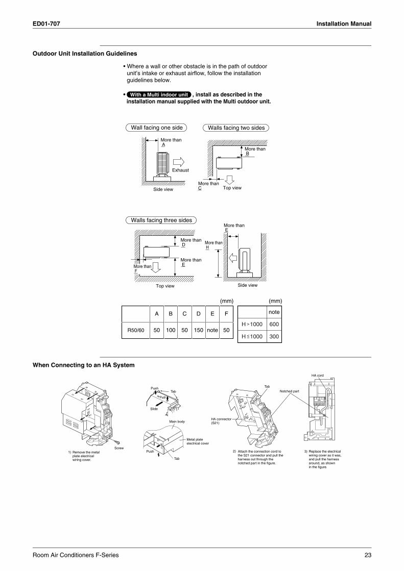
Outdoor Unit Installation Guidelines
When Connecting to an HA System
Wall facing one side
Walls facing three sides
Walls facing two sides
Side view
Side view
Top view
Exhaust
Top view
(mm) (mm)
• Where a wall or other obstacle is in the path of outdoor unit’s intake or exhaust airflow, follow the installation guidelines below.
• , install as described in the installation manual supplied with the Multi outdoor unit.
More than B
More than F
More than A
More than D More than
H
More than E
More than E
More than C
With a Multi indoor unit
50 100 50 150 note 50
A B C D E F
R50/60
note
600
300
H 1000
H 1000
Screw
HA cord
HA connector(S21)
Tab
TabPush
Slide
Push
Metal plate electrical cover
Tab
Push
Main body
Notched part
2) 3) Replace the electrical wiring cover as it was, and pull the harness around, as shown in the figure.
Attach the connection cord to the S21 connector and pull the harness out through the notched part in the figure.
1) Remove the metal plate electrical wiring cover.
Room Air Conditioners F-Series 23
Installation Manual ED01-707
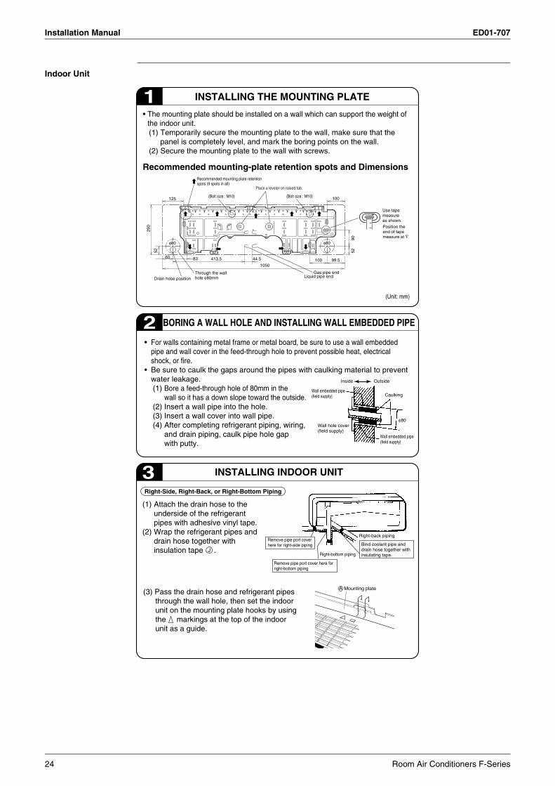
Indoor Unit
BORING A WALL HOLE AND INSTALLING WALL EMBEDDED PIPE2• For walls containing metal frame or metal board, be sure to use a wall embedded
pipe and wall cover in the feed-through hole to prevent possible heat, electrical shock, or fire.
• Be sure to caulk the gaps around the pipes with caulking material to prevent water leakage.(1) Bore a feed-through hole of 80mm in the
wall so it has a down slope toward the outside.(2) Insert a wall pipe into the hole.(3) Insert a wall cover into wall pipe.(4) After completing refrigerant piping, wiring,
and drain piping, caulk pipe hole gap with putty.
INSTALLING INDOOR UNIT
(1) Attach the drain hose to the underside of the refrigerant pipes with adhesive vinyl tape.
(2) Wrap the refrigerant pipes and drain hose together with insulation tape .
Right-Side, Right-Back, or Right-Bottom Piping
(3) Pass the drain hose and refrigerant pipes through the wall hole, then set the indoor unit on the mounting plate hooks by using the markings at the top of the indoor unit as a guide.
Inside Outside
CaulkingWall embedded pipe (field supply)
Wall hole cover(field supply)
Wall embedded pipe (field supply)
φ80
Right-bottom piping
Right-back piping
Bind coolant pipe and drain hose together with insulating tape.
Remove pipe port cover here for right-side piping
Remove pipe port cover here for right-bottom piping
3
INSTALLING THE MOUNTING PLATE1• The mounting plate should be installed on a wall which can support the weight of
the indoor unit.(1) Temporarily secure the mounting plate to the wall, make sure that the
panel is completely level, and mark the boring points on the wall.(2) Secure the mounting plate to the wall with screws.
Recommended mounting-plate retention spots and Dimensions
J
Mounting plateA
(Unit: mm)
125
60 83 413.5 44.5
290
52
105099.5
5290
100
100
Through the wall hole φ80mmDrain hose position
φ80 φ80
Recommended mounting plate retention spots (9 spots in all)
(Bolt size : M10) (Bolt size : M10)
Place a leveler on raised tab.
Use tape measure as shown.Position the end of tape measure at ∇.
Gas pipe end Liquid pipe end
24 Room Air Conditioners F-Series
ED01-707 Installation Manual
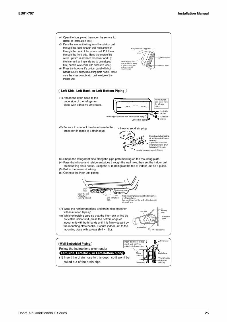
(4) Open the front panel, then open the service lid.(Refer to Installation tips.)
(5) Pass the inter-unit wiring from the outdoor unit through the feed-through wall hole and then through the back of the indoor unit. Pull them through the front side. Bend the ends of tie wires upward in advance for easier work. (If the inter-unit wiring ends are to be stripped first, bundle wire ends with adhesive tape.)
(6) Press the indoor unit’s bottom panel with both hands to set it on the mounting plate hooks. Make sure the wires do not catch on the edge of the indoor unit.
Left-Side, Left-Back, or Left-Bottom Piping
No gapDo not apply lubricating oil (refrigerant oil) when inserting.Application of causes deterioration and drain leakage of the plug.
Insert a hexagon wrench (4mm).
• How to set drain plug
(3) Shape the refrigerant pipe along the pipe path marking on the mounting plate.(4) Pass drain hose and refrigerant pipes through the wall hole, then set the indoor unit
(5) Pull in the inter-unit wiring.(6) Connect the inter-unit piping.
on mounting plate hooks, using the markings at the top of indoor unit as a guide.
Remove pipe port cover here for left-bottom piping
Remove pipe port cover here for left-side piping
Left-bottom piping
Left-side piping
Left-back piping
Follow the instructions given under Left-Side, Left-Back, or Left-Bottom pipng .(1) Insert the drain hose to this depth so it won’t be
pulled out of the drain pipe.
Wall Embedded Piping
Outer wall
Inner wall
Vinyl chloride drain pipe (VP-30)
Drain hose
Insert drain hose to this depth so it won’t be pulled out of drain pipe.
50mm or more
(7) Wrap the refrigerant pipes and drain hose together with insulation tape .
(8) While exercising care so that the inter-unit wiring do not catch indoor unit, press the bottom edge of indoor unit with both hands until it is firmly caught by the mounting plate hooks. Secure indoor unit to the mounting plate with screws (M4 × 12L).
J
When stripping the ends of inter-unit wiring in advance, bind right ends of wires with insulating tape.
Hang indoor unit’s hook here.
Inter-unit wiring
Mounting plateA
(1) Attach the drain hose to the underside of the refrigerant pipes with adhesive vinyl tape.
(2) Be sure to connect the drain hose to the drain port in place of a drain plug.
J
Wrap insulating tape around the bent portion of refrigerant pipe. Overlap at least half the width of the tape with each turn.
Drain hose
Caulk this hole with putty or caulking material. Bind with plastic
tape.
A Mounting plate
Refrigerantpipes
Drain hose
Bottom frame
H M4 × 12L (2 points)
Mountingplate
A
Room Air Conditioners F-Series 25
Installation Manual ED01-707
Shape wires so that the service lid will fit securely.
Terminal block
Electrical component box
Wire retainer
Firmly secure wire retainer so that wires sustain no external stress.Use the
specified wire type.
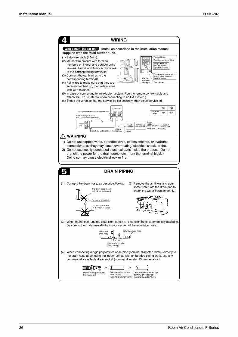
4 WIRING
Powersupply50Hz 220-240V~
60Hz 220V~ : R50/60BVL
Earth
When wire length exceeds 10m, use 2.0mm diameter wires.
H05VVFirmly fix the wires with the terminal screws.
Firmly fix the wires with the terminal screws.
123
1 2 3 L N
Safetybreaker
Earth leakagecircuit breaker
Outdoor unit
Indoor unit
(1) Strip wire ends (15mm).(2) Match wire colours with terminal
numbers on indoor and outdoor units’ terminal blocks and firmly screw wires to the corresponding terminals.
(3) Connect the earth wires to the corresponding terminals.
(4) Pull wires to make sure that they are securely latched up, then retain wires with wire retainer.
(5) In case of connecting to an adapter system. Run the remote control cable and attach the S21. (Refer to when connecting to an HA system.)
(6) Shape the wires so that the service lid fits securely, then close service lid.
Max. Fuse Amps
R60
25A
R50
15A
1) Do not use tapped wires, stranded wires, extensioncords, or starburst connections, as they may cause overheating, electrical shock, or fire.
2) Do not use locally purchased electrical parts inside the product. (Do not branch the power for the drain pump, etc., from the terminal block.) Doing so may cause electric shock or fire.
WARNING
5 DRAIN PIPING
(1) Connect the drain hose, as described below
(3) When drain hose requires extension, obtain an extension hose commercially available. Be sure to thermally insulate the indoor section of the extension hose.
Indoor unit drain hose
Extension drain hose
Heat insulation tube(Field supply)
(4) When connecting a rigid polyvinyl chloride pipe (nominal diameter 13mm) directly to the drain hose attached to the indoor unit as with embedded piping work, use any commercially available drain socket (nominal diameter 13mm) as a joint.
The drain hose should be inclined downward.
No trap is permitted.
Do not put the end of the hose in water.
(2) Remove the air filters and pour some water into the drain pan to check the water flows smoothly.
Drain hose supplied with the indoor unit
Commercially available drain socket (nominal diameter 13mm)
Commercially available rigid polyvinyl chloride pipe(nominal diameter 13mm)
R50/60BV1R50/60CV1A
, install as described in the installation manual supplied with the Multi outdoor unit.
With a multi indoor unit
26 Room Air Conditioners F-Series
ED01-707 Installation Manual
Outdoor Unit
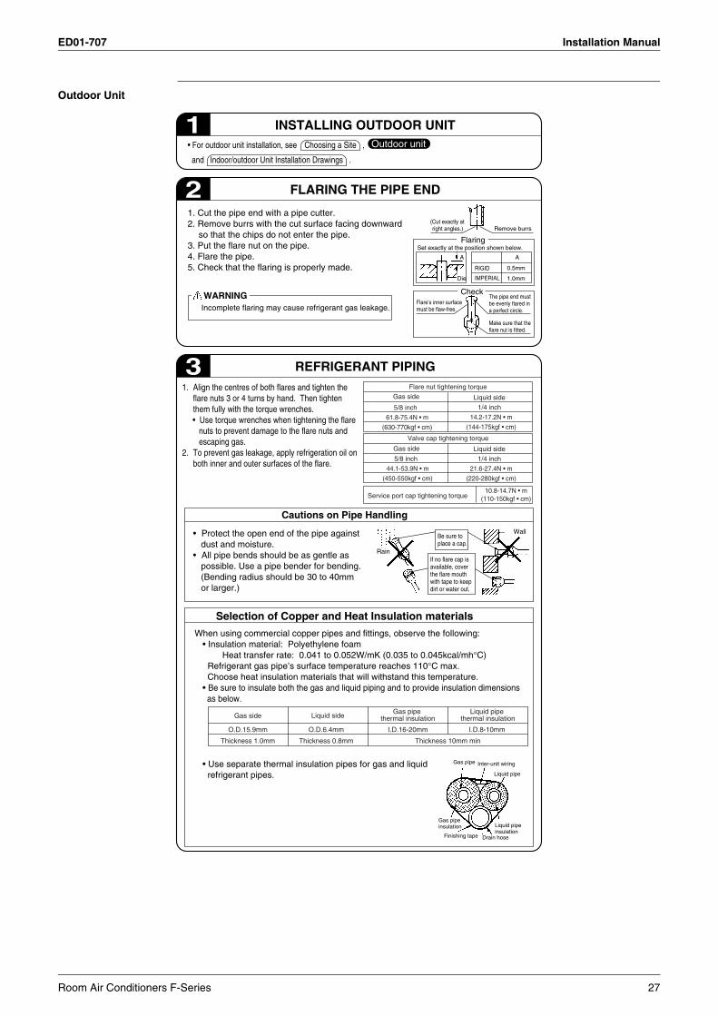
INSTALLING OUTDOOR UNIT• For outdoor unit installation, see Choosing a Site ,
and Indoor/outdoor Unit Installation Drawings .
Outdoor unit1
FLARING THE PIPE END
1. Cut the pipe end with a pipe cutter.2. Remove burrs with the cut surface facing downward
so that the chips do not enter the pipe.3. Put the flare nut on the pipe.4. Flare the pipe.5. Check that the flaring is properly made.
2
REFRIGERANT PIPING
Cautions on Pipe Handling
3
Selection of Copper and Heat Insulation materials
(Cut exactly at right angles.) Remove burrs
Set exactly at the position shown below.
A A
IMPERIAL
RIGID
Die
0.5mm
1.0mm
Flaring
Incomplete flaring may cause refrigerant gas leakage.
WARNINGFlare’s inner surface must be flaw-free.
CheckThe pipe end must be evenly flared in a perfect circle.
Make sure that the flare nut is fitted.
Wall
If no flare cap is available, cover the flare mouth with tape to keep dirt or water out.
Be sure to place a cap.
Rain
Gas pipe
Liquid pipe
Gas pipe insulation Liquid pipe
insulationFinishing tape Drain hose
Inter-unit wiring
When using commercial copper pipes and fittings, observe the following:• Insulation material: Polyethylene foam Heat transfer rate: 0.041 to 0.052W/mK (0.035 to 0.045kcal/mh°C)Refrigerant gas pipe’s surface temperature reaches 110°C max. Choose heat insulation materials that will withstand this temperature.
• Be sure to insulate both the gas and liquid piping and to provide insulation dimensions as below.
• Use separate thermal insulation pipes for gas and liquid refrigerant pipes.
Flare nut tightening torque
5/8 inch
61.8-75.4N • m
(630-770kgf • cm)
Liquid side
1/4 inch
14.2-17.2N • m
(144-175kgf • cm)
Service port cap tightening torque10.8-14.7N • m
(110-150kgf • cm)
1. Align the centres of both flares and tighten the flare nuts 3 or 4 turns by hand. Then tighten them fully with the torque wrenches.
• Use torque wrenches when tightening the flare nuts to prevent damage to the flare nuts and escaping gas.
2. To prevent gas leakage, apply refrigeration oil on both inner and outer surfaces of the flare.
Valve cap tightening torque
5/8 inch
44.1-53.9N • m
(450-550kgf • cm)
Liquid side
1/4 inch
21.6-27.4N • m
(220-280kgf • cm)
• Protect the open end of the pipe against dust and moisture.
• All pipe bends should be as gentle as possible. Use a pipe bender for bending. (Bending radius should be 30 to 40mm or larger.)
O.D.15.9mm
Thickness 1.0mm
O.D.6.4mm
Thickness 0.8mm
Liquid side
Thickness 10mm min
I.D.8-10mm
Liquid pipe thermal insulationGas side
I.D.16-20mm
Gas pipe thermal insulation
Gas side
Gas side
Room Air Conditioners F-Series 27
Installation Manual ED01-707
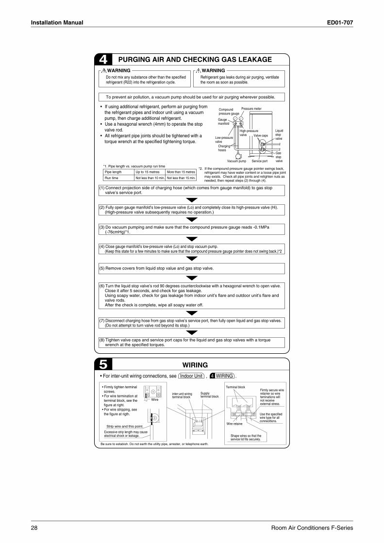
PURGING AIR AND CHECKING GAS LEAKAGE4Do not mix any substance other than the specified refrigerant (R22) into the refrigeration cycle.
WARNING
To prevent air pollution, a vacuum pump should be used for air purging wherever possible.
Refrigerant gas leaks during air purging, ventilate the room as soon as possible.
WARNING
*1. Pipe length vs. vacuum pump run time
Pipe length
Run time
Up to 15 metres
Not less than 10 min.
More than 15 metres
Not less than 15 min.
WIRING
• For inter-unit wiring connections, see Indoor Unit , 4. WIRING .
• Firmly tighten terminal screws.• For wire termination at terminal block, see the figure at right.• For wire stripping, see the figure at rigth.
5
Terminal block
inter-unit wiringterminal block
Supplyterminal block
Strip wire and this point.
Excessive strip length may causeelectrical shock or leskage.
Wire
Be sure to estabish. Do not earth the utiilty pipe, arrester, or telephone earth.
Wire retaine
Shape wires so that theservice lid fits securely.
Use the specifiedwire type for allconnecitions.
Firmly secure wireretainer so wireteminations willnot receiveexternal stress.
Gauge manifold
Compound pressure gauge
Pressure meter
Low-pressure valve
Charging hoses
Vacuum pump
Valve caps
Service port
Liquid stop valve
Gas stop valve
High-pressure valve
• If using additional refrigerant, perform air purging from the refrigerant pipes and indoor unit using a vacuum pump, then charge additional refrigerant.
• Use a hexagonal wrench (4mm) to operate the stop valve rod.
• All refrigerant pipe joints should be tightened with a torque wrench at the specified tightening torque.
*2. If the compound pressure gauge pointer swings back, refrigerant may have water content or a loose pipe joint may exists. Check all pipe joints and retighten nuts as needed, then repeat steps (2) through (4).
(1) Connect projection side of charging hose (which comes from gauge manifold) to gas stop valve’s service port.
(2) Fully open gauge manifold’s low-pressure valve (Lo) and completely close its high-pressure valve (Hi).(High-pressure valve subsequently requires no operation.)
(3) Do vacuum pumping and make sure that the compound pressure gauge reads -0.1MPa (-76cmHg)*1.
(4) Close gauge manifold’s low-pressure valve (Lo) and stop vacuum pump. (Keep this state for a few minutes to make sure that the compound pressure gauge pointer does not swing back.)*2
(7) Disconnect charging hose from gas stop valve’s service port, then fully open liquid and gas stop valves. (Do not attempt to turn valve rod beyond its stop.)
(6) Turn the liquid stop valve’s rod 90 degrees counterclockwise with a hexagonal wrench to open valve. Close it after 5 seconds, and check for gas leakage.Using soapy water, check for gas leakage from indoor unit’s flare and outdoor unit’s flare and valve rods. After the check is complete, wipe all soapy water off.
(5) Remove covers from liquid stop value and gas stop valve.
(8) Tighten valve caps and service port caps for the liquid and gas stop valves with a torque wrench at the specified torques.
28 Room Air Conditioners F-Series
ED01-707 Installation Manual
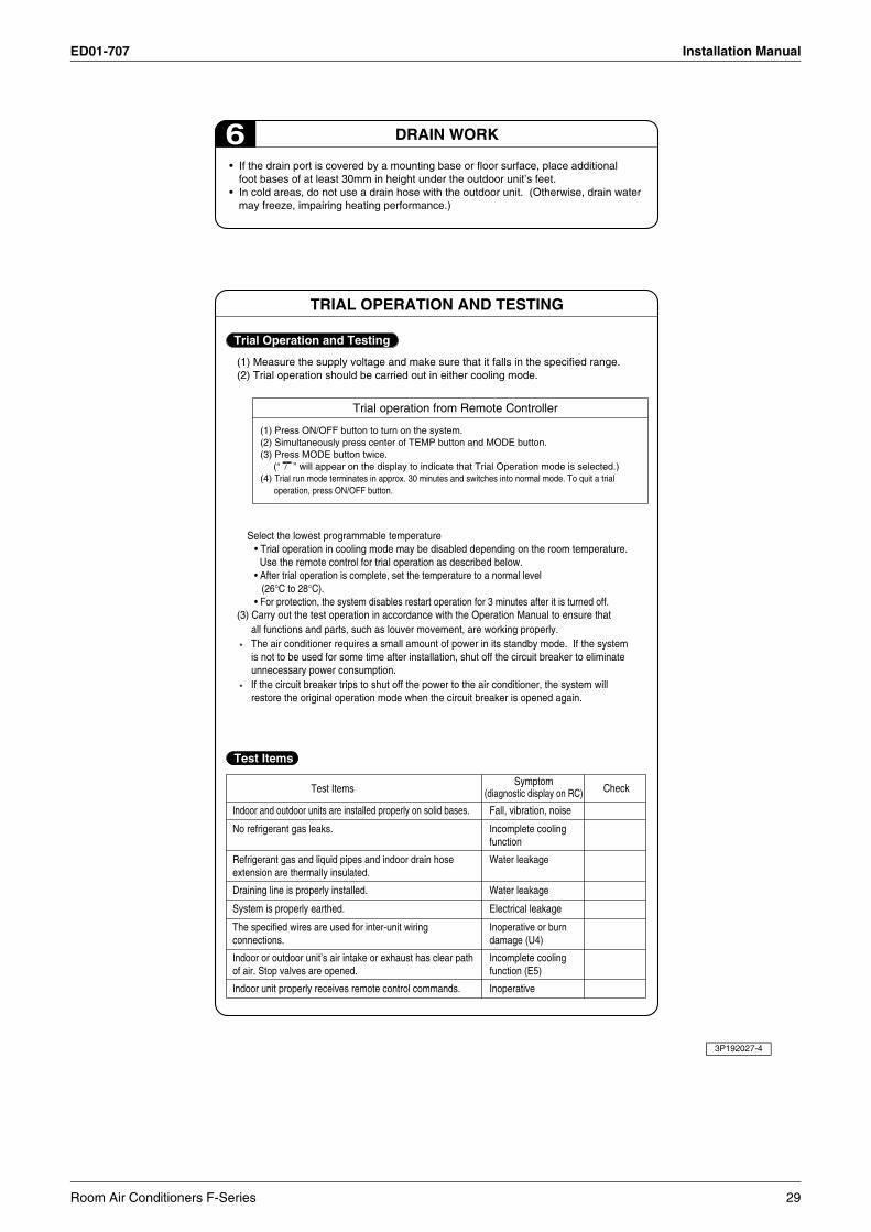
DRAIN WORK6• If the drain port is covered by a mounting base or floor surface, place additional
foot bases of at least 30mm in height under the outdoor unit’s feet.• In cold areas, do not use a drain hose with the outdoor unit. (Otherwise, drain water
may freeze, impairing heating performance.)
Trial Operation and Testing
Test Items
(1) Measure the supply voltage and make sure that it falls in the specified range.(2) Trial operation should be carried out in either cooling mode.
• After trial operation is complete, set the temperature to a normal level (26°C to 28°C).
• For protection, the system disables restart operation for 3 minutes after it is turned off.
Select the lowest programmable temperature• Trial operation in cooling mode may be disabled depending on the room temperature. Use the remote control for trial operation as described below.
(3) Carry out the test operation in accordance with the Operation Manual to ensure that all functions and parts, such as louver movement, are working properly.
* The air conditioner requires a small amount of power in its standby mode. If the system is not to be used for some time after installation, shut off the circuit breaker to eliminate unnecessary power consumption.
* If the circuit breaker trips to shut off the power to the air conditioner, the system will restore the original operation mode when the circuit breaker is opened again.
Test ItemsSymptom
(diagnostic display on RC) Check
Indoor and outdoor units are installed properly on solid bases.
No refrigerant gas leaks.
Refrigerant gas and liquid pipes and indoor drain hose extension are thermally insulated.
Draining line is properly installed.
System is properly earthed.
The specified wires are used for inter-unit wiring connections.
Indoor or outdoor unit’s air intake or exhaust has clear path of air. Stop valves are opened.
Indoor unit properly receives remote control commands.
Fall, vibration, noise
Incomplete coolingfunction
Water leakage
Water leakage
Electrical leakage
Inoperative or burn damage (U4)
Incomplete coolingfunction (E5)
Inoperative
Trial operation from Remote Controller
(1) Press ON/OFF button to turn on the system.(2) Simultaneously press center of TEMP button and MODE button.(3) Press MODE button twice. (“ ” will appear on the display to indicate that Trial Operation mode is selected.)(4) Trial run mode terminates in approx. 30 minutes and switches into normal mode. To quit a trial operation, press ON/OFF button.
TRIAL OPERATION AND TESTING
3P192027-4
Room Air Conditioners F-Series 29
Operation Manual ED01-707
13.Operation Manual
2
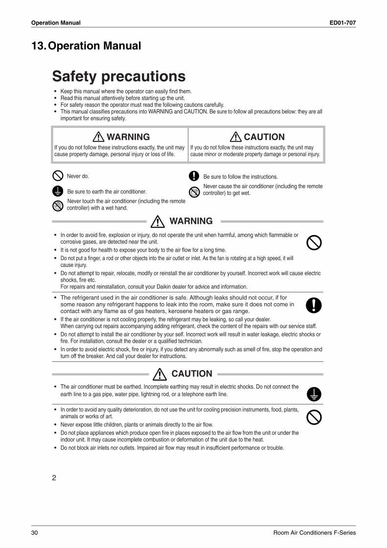
Safety precautions• Keep this manual where the operator can easily find them.• Read this manual attentively before starting up the unit.• For safety reason the operator must read the following cautions carefully.• This manual classifies precautions into WARNING and CAUTION. Be sure to follow all precautions below: they are all
important for ensuring safety.
WARNING• In order to avoid fire, explosion or injury, do not operate the unit when harmful, among which flammable or
corrosive gases, are detected near the unit.• It is not good for health to expose your body to the air flow for a long time.• Do not put a finger, a rod or other objects into the air outlet or inlet. As the fan is rotating at a high speed, it will
cause injury.• Do not attempt to repair, relocate, modify or reinstall the air conditioner by yourself. Incorrect work will cause electric
shocks, fire etc. For repairs and reinstallation, consult your Daikin dealer for advice and information.
• The refrigerant used in the air conditioner is safe. Although leaks should not occur, if for some reason any refrigerant happens to leak into the room, make sure it does not come in contact with any flame as of gas heaters, kerosene heaters or gas range.
• If the air conditioner is not cooling properly, the refrigerant may be leaking, so call your dealer.When carrying out repairs accompanying adding refrigerant, check the content of the repairs with our service staff.
• Do not attempt to install the air conditioner by your self. Incorrect work will result in water leakage, electric shocks or fire. For installation, consult the dealer or a qualified technician.
• In order to avoid electric shock, fire or injury, if you detect any abnormally such as smell of fire, stop the operation and turn off the breaker. And call your dealer for instructions.
CAUTION• The air conditioner must be earthed. Incomplete earthing may result in electric shocks. Do not connect the
earth line to a gas pipe, water pipe, lightning rod, or a telephone earth line.
• In order to avoid any quality deterioration, do not use the unit for cooling precision instruments, food, plants, animals or works of art.
• Never expose little children, plants or animals directly to the air flow.• Do not place appliances which produce open fire in places exposed to the air flow from the unit or under the
indoor unit. It may cause incomplete combustion or deformation of the unit due to the heat.• Do not block air inlets nor outlets. Impaired air flow may result in insufficient performance or trouble.
WARNINGIf you do not follow these instructions exactly, the unit may cause property damage, personal injury or loss of life.
CAUTIONIf you do not follow these instructions exactly, the unit may cause minor or moderate property damage or personal injury.
Never do. Be sure to follow the instructions.
Be sure to earth the air conditioner.Never cause the air conditioner (including the remote controller) to get wet.
Never touch the air conditioner (including the remote controller) with a wet hand.
30 Room Air Conditioners F-Series
ED01-707 Operation Manual
3
• Do not stand or sit on the outdoor unit. Do not place any object on the unit to avoid injury.• Do not place anything under the indoor or outdoor unit that must be kept away from moisture. In certain conditions,
moisture in the air may condense and drip.• After a long use, check the unit stand and fittings for damage.• Do not touch the air inlet and alminum fins of outdoor unit. It may cause injury.• The appliance is not intended for use by young children or infirm persons without supervision.• Young children should be supervised to ensure that they do not play with the appliance.
• To avoid oxygen deficiency, ventilate the room sufficiently if equipment with burner is used together with the air conditioner.
• Before cleaning, be sure to stop the operation, turn the breaker off or pull out the supply cord.• Do not connect the air conditioner to a power supply different from the one as specified. It may cause trou-
ble or fire.• Depending on the environment, an earth leakage breaker must be installed. Lack of an earth leakage breaker may
result in electric shocks.• Arrange the drain hose to ensure smooth drainage. Incomplete draining may cause wetting of the building, furniture
etc.• Do not place objects in direct proximity of the outdoor unit and do not let leaves and other debris accumulate around
the unit. Leaves are a hotbed for small animals which can enter the unit. Once in the unit, such animals can cause malfunc-tions, smoke or fire when making contact with electrical parts.
• Do not operate the air conditioner with wet hands.
• Do not wash the indoor unit with excessive water, only use a slightly wet cloth.• Do not place things such as vessels containing water or anything else on top of the unit. Water may pene-
trate into the unit and degrade electrical insulations, resulting in an electric shock.
To install the air conditioner in the following types of environments, consult the dealer.• Places with an oily ambient or where steam or soot occurs.• Salty environment such as coastal areas.• Places where sulfide gas occurs such as hot springs.• Places where snow may block the outdoor unit.
The drain from the outdoor unit must be discharged to a place of good drainage.
For installation, choose a place as described below.• A place solid enough to bear the weight of the unit which does not amplify the operation noise or vibration.• A place from where the air discharged from the outdoor unit or the operation noise will not annoy
your neighbours.
• For power supply, be sure to use a separate power circuit dedicated to the air conditioner.
• Relocating the air conditioner requires specialized knowledge and skills. Please consult the dealer if reloca-tion is necessary for moving or remodeling.
Installation site.
Consider nuisance to your neighbours from noises.
Electrical work.
System relocation.
Room Air Conditioners F-Series 31
Operation Manual ED01-707
4
Names of parts
Indoor Unit
12
43
9 10 86
7
13
11
12
14
5
32 Room Air Conditioners F-Series
ED01-707 Operation Manual
5
Outdoor Unit
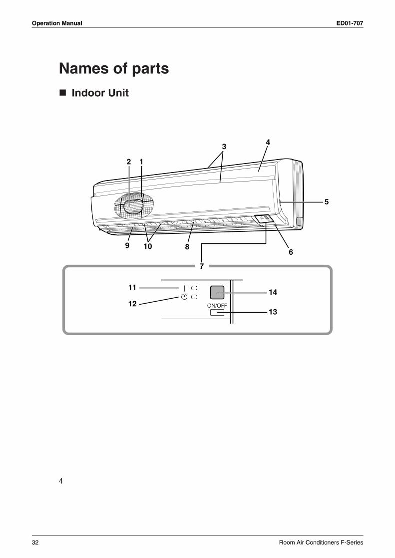
Indoor Unit1. Air filter
2. Titanium Apatite PhotocatalyticAir-Purifying Filter
3. Air inlet
4. Front panel
5. Panel tab
6. Room temperature sensor:• It senses the air temperature around the unit.
7. Display
8. Air outlet
9. Flap (horizontal blade): (page 12.)
10. Louvers (vertical blades):• The Louvers are inside of the air outlet.
(page 12.)
11. Operation lamp (green)
12. TIMER lamp (yellow): (page 14.)
13. Indoor Unit ON/OFF switch:• Push this switch once to start operation.
Push once again to stop it.• The operation mode refer to the following table.
• This switch is useful when the remote controller is missing.
14. Signal receiver:• It receives signals from the remote controller.• When the unit receives a signal, you will hear a
short beep.• Operation start .............beep-beep• Settings changed..........beep• Operation stop ..............beeeeep
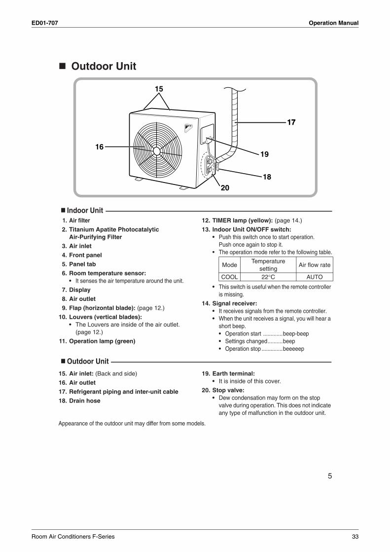
Outdoor Unit
15. Air inlet: (Back and side)
16. Air outlet
17. Refrigerant piping and inter-unit cable
18. Drain hose
19. Earth terminal:• It is inside of this cover.
20. Stop valve:• Dew condensation may form on the stop
valve during operation. This does not indicate any type of malfunction in the outdoor unit.
Appearance of the outdoor unit may differ from some models.
17
1619
18
17
15
20
ModeTemperature
settingAir flow rate
COOL 22°C AUTO
Room Air Conditioners F-Series 33
Operation Manual ED01-707
6
Remote Controller
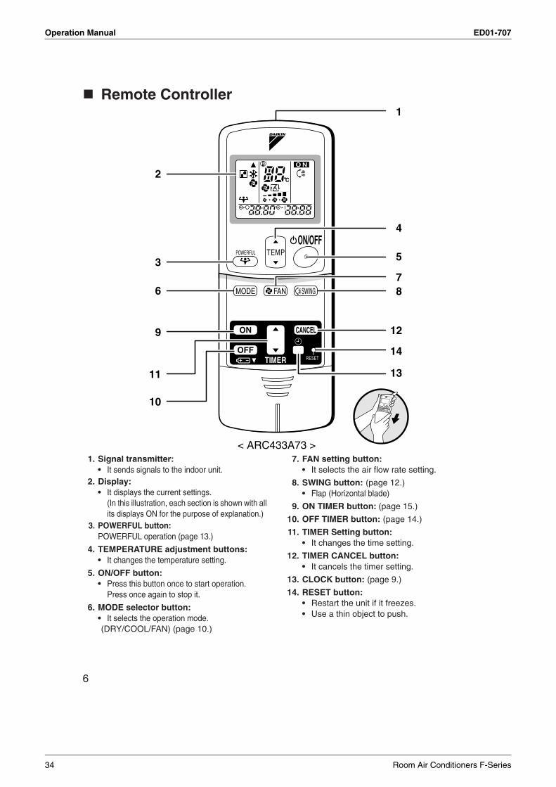
1. Signal transmitter:• It sends signals to the indoor unit.
2. Display:• It displays the current settings.
(In this illustration, each section is shown with all its displays ON for the purpose of explanation.)
3. POWERFUL button: POWERFUL operation (page 13.)
4. TEMPERATURE adjustment buttons:• It changes the temperature setting.
5. ON/OFF button:• Press this button once to start operation.
Press once again to stop it.
6. MODE selector button:• It selects the operation mode.(DRY/COOL/FAN) (page 10.)
7. FAN setting button:• It selects the air flow rate setting.
8. SWING button: (page 12.)• Flap (Horizontal blade)
9. ON TIMER button: (page 15.)
10. OFF TIMER button: (page 14.)
11. TIMER Setting button:• It changes the time setting.
12. TIMER CANCEL button:• It cancels the timer setting.
13. CLOCK button: (page 9.)
14. RESET button:• Restart the unit if it freezes.• Use a thin object to push.
1
4
5
78
< ARC433A73 >
2
9
11
10
3
6
12
14
13
34 Room Air Conditioners F-Series
ED01-707 Operation Manual
7
Preparation Before Operation
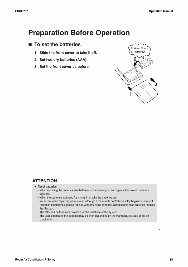
To set the batteries
1. Slide the front cover to take it off.
2. Set two dry batteries (AAA).
3. Set the front cover as before.
ATTENTIONAbout batteries• When replacing the batteries, use batteries of the same type, and replace the two old batteries
together.• When the system is not used for a long time, take the batteries out.• We recommend replacing once a year, although if the remote controller display begins to fade or if
reception deteriorates, please replace with new alkali batteries. Using manganese batteries reduces the lifespan.
• The attached batteries are provided for the initial use of the system.The usable period of the batteries may be short depending on the manufactured date of the air conditioner.
2
3
1
Position and correctly!
+–
Room Air Conditioners F-Series 35
Operation Manual ED01-707
8
Preparation Before Operation
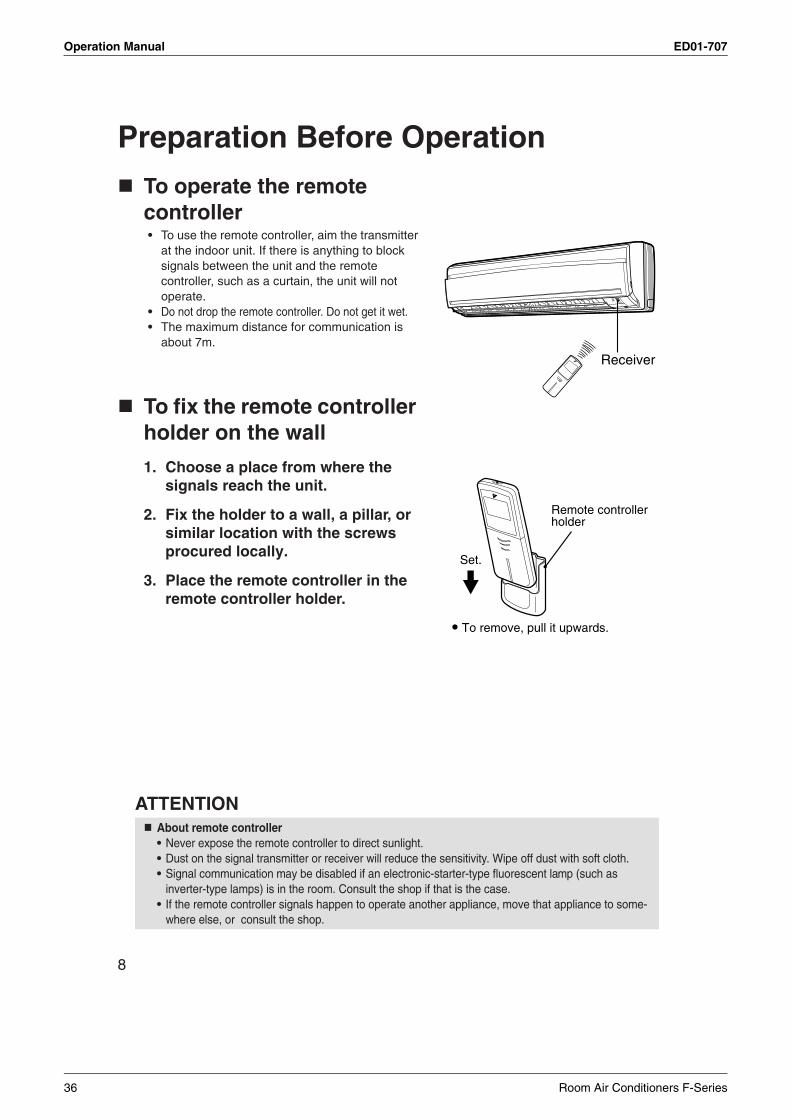
To operate the remote controller• To use the remote controller, aim the transmitter
at the indoor unit. If there is anything to block signals between the unit and the remote controller, such as a curtain, the unit will not operate.
• Do not drop the remote controller. Do not get it wet.• The maximum distance for communication is
about 7m.
To fix the remote controller holder on the wall
1. Choose a place from where the signals reach the unit.
2. Fix the holder to a wall, a pillar, or similar location with the screws procured locally.
3. Place the remote controller in the remote controller holder.
ATTENTIONAbout remote controller• Never expose the remote controller to direct sunlight.• Dust on the signal transmitter or receiver will reduce the sensitivity. Wipe off dust with soft cloth.• Signal communication may be disabled if an electronic-starter-type fluorescent lamp (such as
inverter-type lamps) is in the room. Consult the shop if that is the case.• If the remote controller signals happen to operate another appliance, move that appliance to some-
where else, or consult the shop.
Receiver
Remote controller holder
Set.
To remove, pull it upwards.
36 Room Air Conditioners F-Series
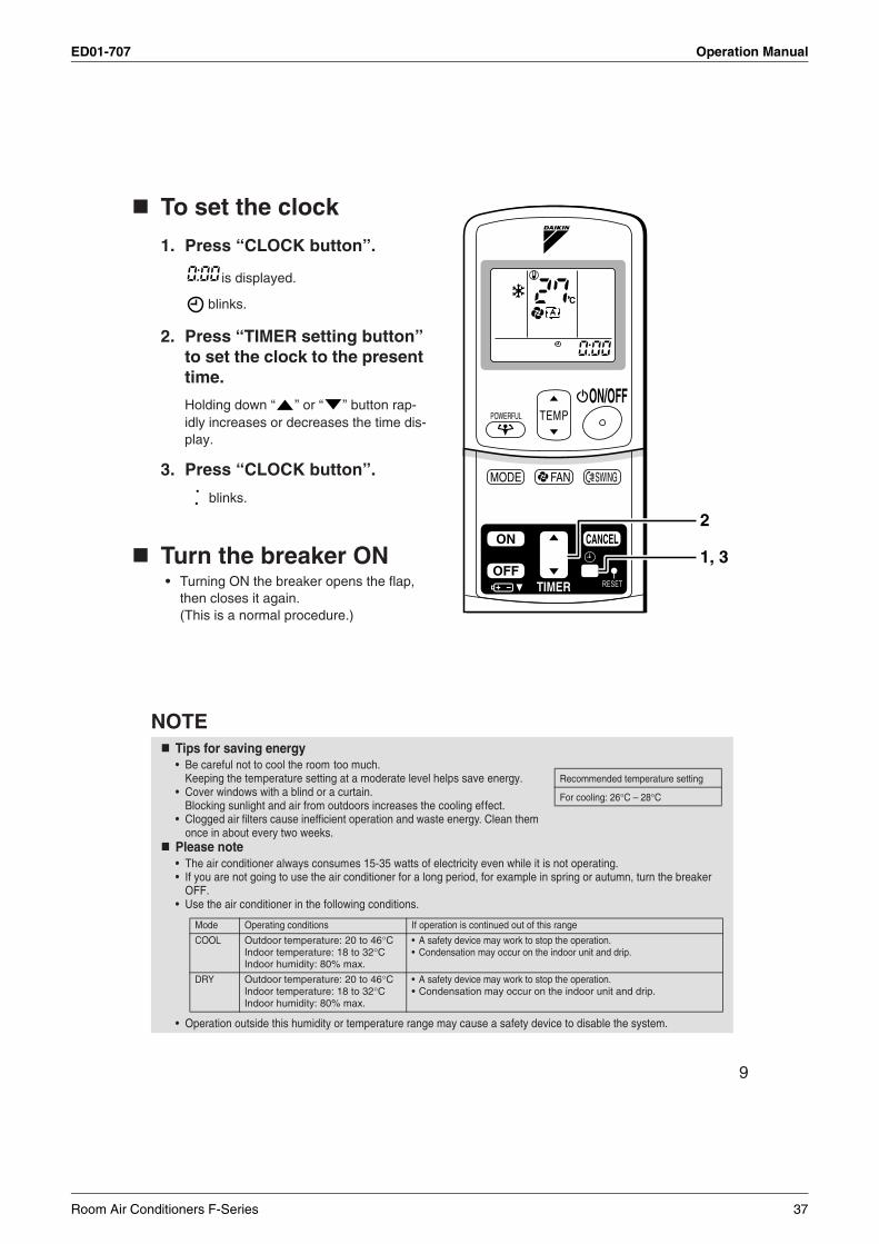
ED01-707 Operation Manual
9
To set the clock
1. Press “CLOCK button”.
is displayed.
blinks.
2. Press “TIMER setting button” to set the clock to the present time.
Holding down “ ” or “ ” button rap-idly increases or decreases the time dis-play.
3. Press “CLOCK button”.
blinks.
Turn the breaker ON• Turning ON the breaker opens the flap,
then closes it again. (This is a normal procedure.)
NOTETips for saving energy• Be careful not to cool the room too much.
Keeping the temperature setting at a moderate level helps save energy.• Cover windows with a blind or a curtain.
Blocking sunlight and air from outdoors increases the cooling effect.• Clogged air filters cause inefficient operation and waste energy. Clean them
once in about every two weeks.Please note• The air conditioner always consumes 15-35 watts of electricity even while it is not operating.• If you are not going to use the air conditioner for a long period, for example in spring or autumn, turn the breaker
OFF.• Use the air conditioner in the following conditions.
• Operation outside this humidity or temperature range may cause a safety device to disable the system.
1, 3
2
Recommended temperature setting
For cooling: 26°C – 28°C
Mode Operating conditions If operation is continued out of this range
COOL Outdoor temperature: 20 to 46°CIndoor temperature: 18 to 32°CIndoor humidity: 80% max.
• A safety device may work to stop the operation.• Condensation may occur on the indoor unit and drip.
DRY Outdoor temperature: 20 to 46°CIndoor temperature: 18 to 32°CIndoor humidity: 80% max.
• A safety device may work to stop the operation.• Condensation may occur on the indoor unit and drip.
Room Air Conditioners F-Series 37
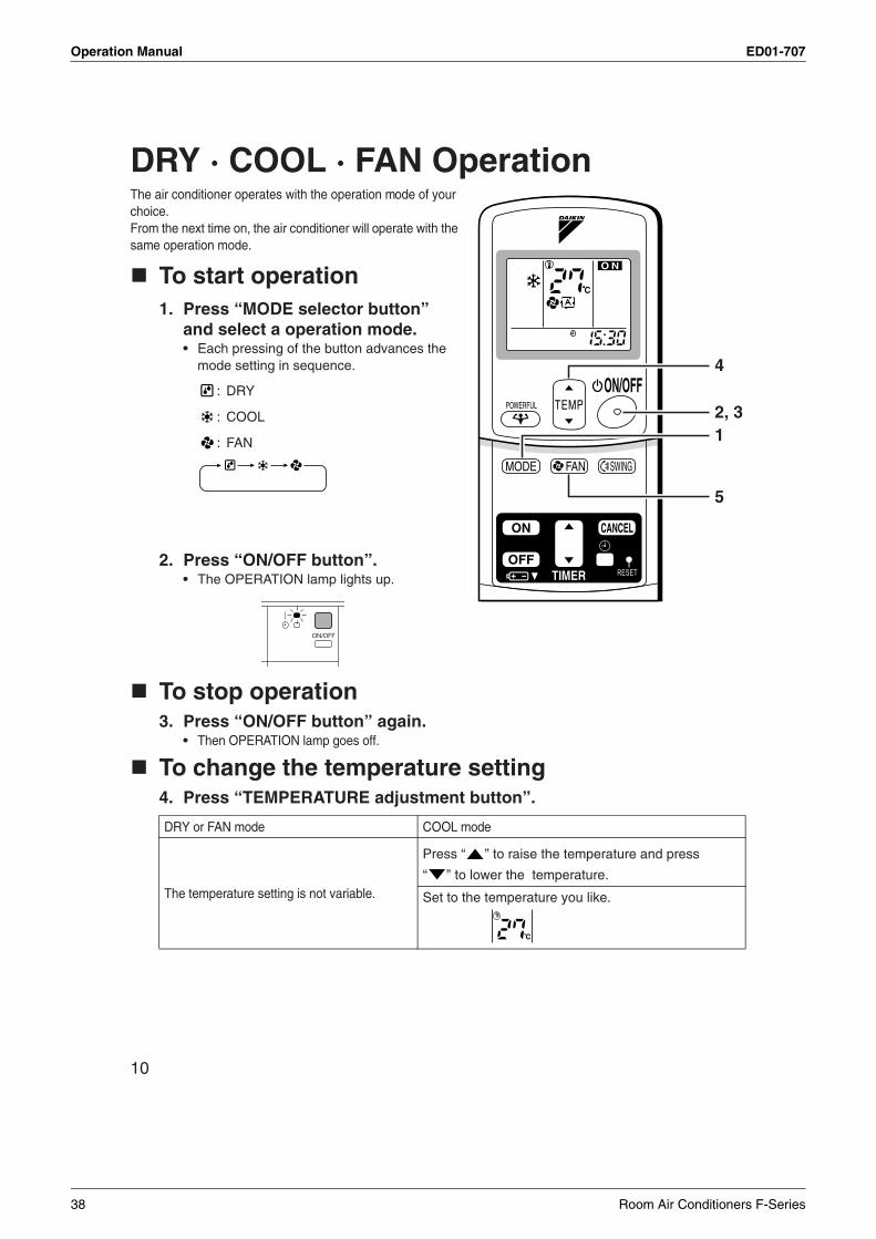
Operation Manual ED01-707
10
DRY · COOL · FAN OperationThe air conditioner operates with the operation mode of your choice.From the next time on, the air conditioner will operate with the same operation mode.
To start operation1. Press “MODE selector button”
and select a operation mode.• Each pressing of the button advances the
mode setting in sequence.
: DRY
: COOL
: FAN
2. Press “ON/OFF button”.• The OPERATION lamp lights up.
To stop operation3. Press “ON/OFF button” again.
• Then OPERATION lamp goes off.
To change the temperature setting4. Press “TEMPERATURE adjustment button”.
DRY or FAN mode COOL mode
The temperature setting is not variable.
Press “ ” to raise the temperature and press
“ ” to lower the temperature.
Set to the temperature you like.
2, 31
4
5
38 Room Air Conditioners F-Series
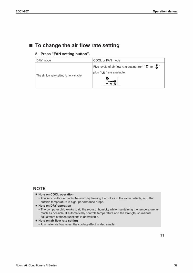
ED01-707 Operation Manual
11
To change the air flow rate setting
5. Press “FAN setting button”.
NOTE
DRY mode COOL or FAN mode
The air flow rate setting is not variable.
Five levels of air flow rate setting from “ ” to “ ”
plus “ ” are available.
Note on COOL operation• This air conditioner cools the room by blowing the hot air in the room outside, so if the
outside temperature is high, performance drops.Note on DRY operation• The computer chip works to rid the room of humidity while maintaining the temperature as
much as possible. It automatically controls temperature and fan strength, so manual adjustment of these functions is unavailable.
Note on air flow rate setting• At smaller air flow rates, the cooling effect is also smaller.
Room Air Conditioners F-Series 39
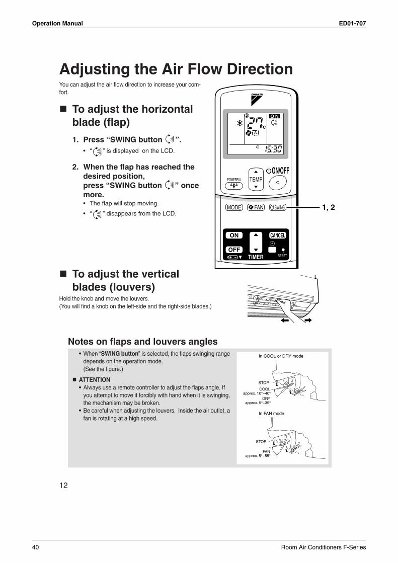
Operation Manual ED01-707
12
Adjusting the Air Flow DirectionYou can adjust the air flow direction to increase your com-fort.
To adjust the horizontal blade (flap)
1. Press “SWING button ”.• “ ” is displayed on the LCD.
2. When the flap has reached the desired position, press “SWING button ” once more.• The flap will stop moving.
• “ ” disappears from the LCD.
To adjust the vertical blades (louvers)
Hold the knob and move the louvers.(You will find a knob on the left-side and the right-side blades.)
Notes on flaps and louvers angles• When “SWING button” is selected, the flaps swinging range
depends on the operation mode. (See the figure.)
ATTENTION• Always use a remote controller to adjust the flaps angle. If
you attempt to move it forcibly with hand when it is swinging, the mechanism may be broken.
• Be careful when adjusting the louvers. Inside the air outlet, a fan is rotating at a high speed.
1, 2
STOP
COOLapprox. 10°~40°
DRYapprox. 5°~35°
In COOL or DRY mode
STOP
FANapprox. 5°~55°
In FAN mode
40 Room Air Conditioners F-Series
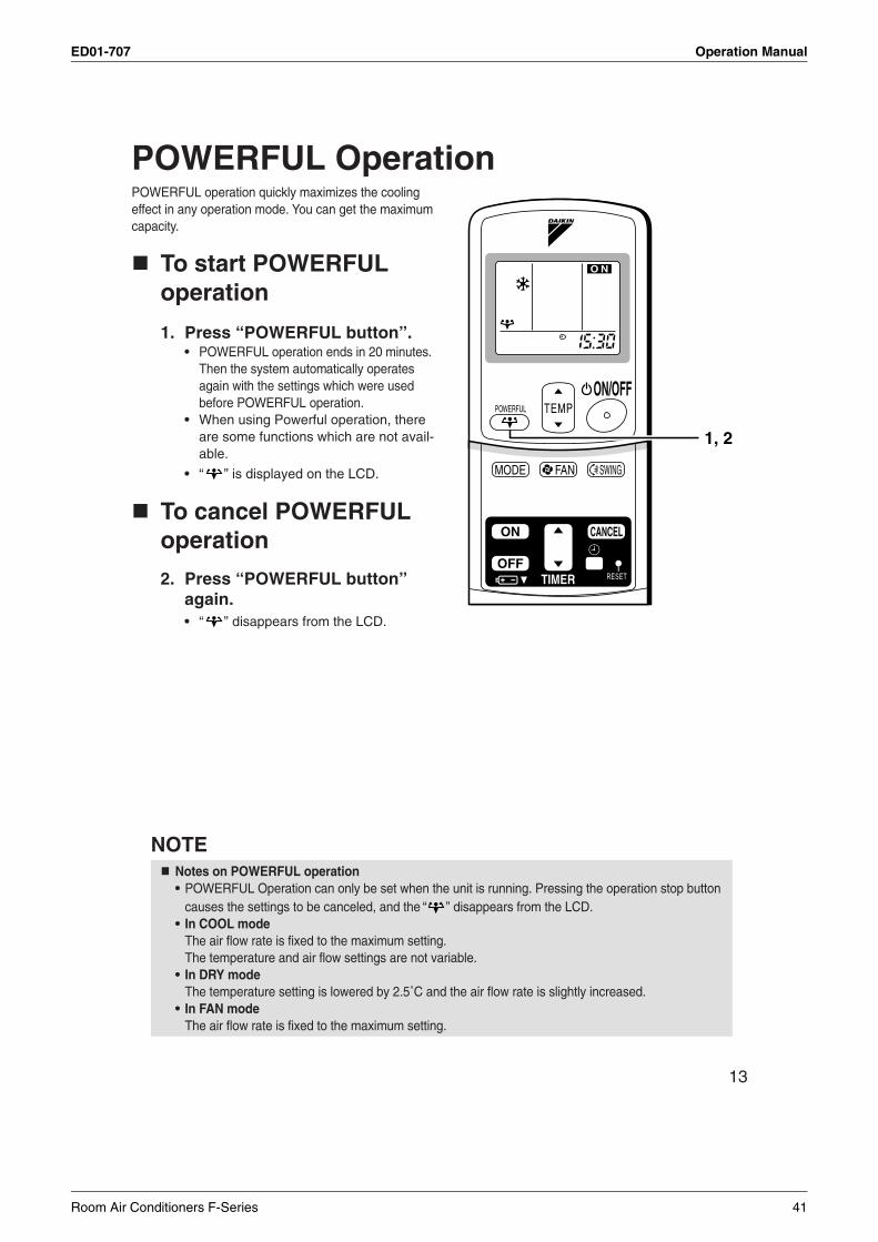
ED01-707 Operation Manual
13
POWERFUL OperationPOWERFUL operation quickly maximizes the cooling effect in any operation mode. You can get the maximum capacity.
To start POWERFUL operation
1. Press “POWERFUL button”.• POWERFUL operation ends in 20 minutes.
Then the system automatically operates again with the settings which were used before POWERFUL operation.
• When using Powerful operation, there are some functions which are not avail-able.
• “ ” is displayed on the LCD.
To cancel POWERFUL operation
2. Press “POWERFUL button” again.• “ ” disappears from the LCD.
NOTENotes on POWERFUL operation• POWERFUL Operation can only be set when the unit is running. Pressing the operation stop button
causes the settings to be canceled, and the “ ” disappears from the LCD.• In COOL mode
The air flow rate is fixed to the maximum setting.The temperature and air flow settings are not variable.
• In DRY modeThe temperature setting is lowered by 2.5˚C and the air flow rate is slightly increased.
• In FAN modeThe air flow rate is fixed to the maximum setting.
1, 2
Room Air Conditioners F-Series 41
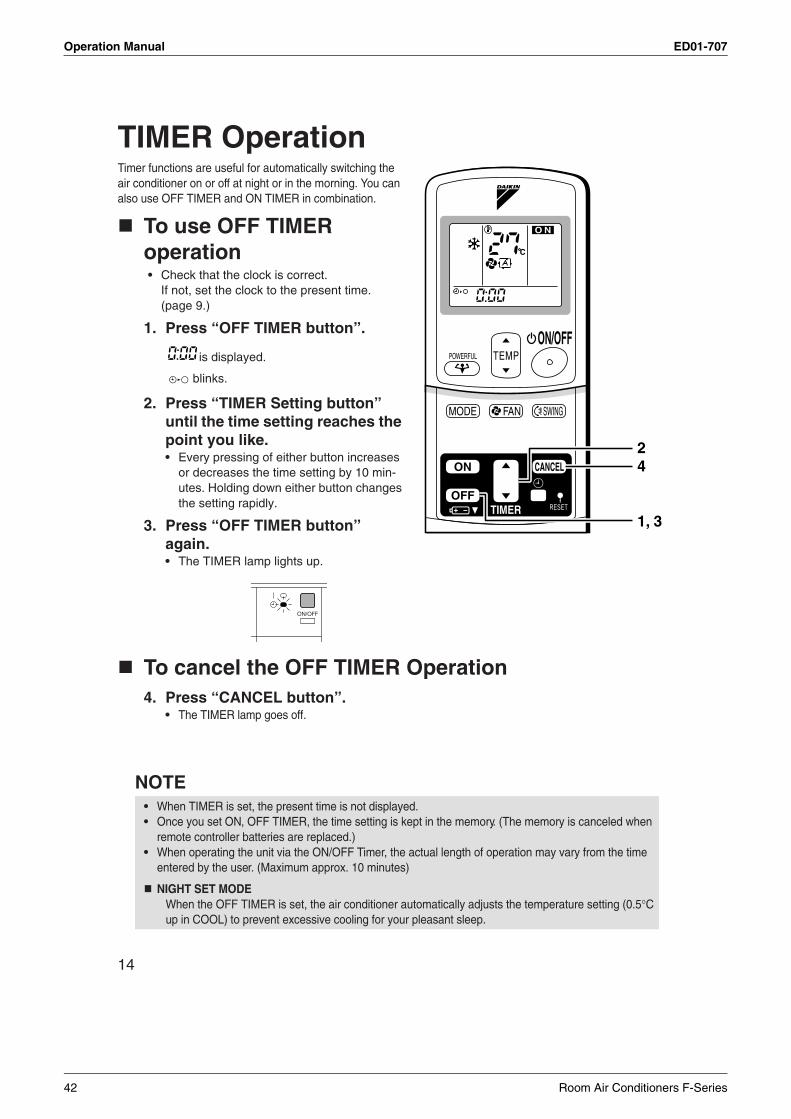
Operation Manual ED01-707
14
TIMER OperationTimer functions are useful for automatically switching the air conditioner on or off at night or in the morning. You can also use OFF TIMER and ON TIMER in combination.
To use OFF TIMER operation• Check that the clock is correct.
If not, set the clock to the present time. (page 9.)
1. Press “OFF TIMER button”.
is displayed.
blinks.
2. Press “TIMER Setting button” until the time setting reaches the point you like.• Every pressing of either button increases
or decreases the time setting by 10 min-utes. Holding down either button changes the setting rapidly.
3. Press “OFF TIMER button” again.• The TIMER lamp lights up.
To cancel the OFF TIMER Operation4. Press “CANCEL button”.
• The TIMER lamp goes off.
NOTE• When TIMER is set, the present time is not displayed.• Once you set ON, OFF TIMER, the time setting is kept in the memory. (The memory is canceled when
remote controller batteries are replaced.)• When operating the unit via the ON/OFF Timer, the actual length of operation may vary from the time
entered by the user. (Maximum approx. 10 minutes)
NIGHT SET MODEWhen the OFF TIMER is set, the air conditioner automatically adjusts the temperature setting (0.5°C up in COOL) to prevent excessive cooling for your pleasant sleep.
42
1, 3
42 Room Air Conditioners F-Series
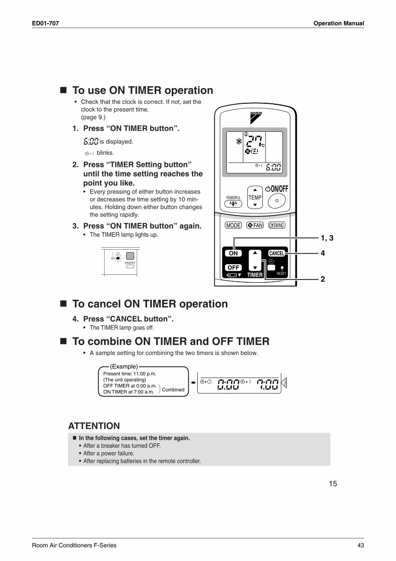
ED01-707 Operation Manual
15
To use ON TIMER operation• Check that the clock is correct. If not, set the
clock to the present time.(page 9.)
1. Press “ON TIMER button”.
is displayed.
blinks.
2. Press “TIMER Setting button” until the time setting reaches the point you like.• Every pressing of either button increases
or decreases the time setting by 10 min-utes. Holding down either button changes the setting rapidly.
3. Press “ON TIMER button” again.• The TIMER lamp lights up.
To cancel ON TIMER operation4. Press “CANCEL button”.
• The TIMER lamp goes off.
To combine ON TIMER and OFF TIMER• A sample setting for combining the two timers is shown below.
ATTENTIONIn the following cases, set the timer again.• After a breaker has turned OFF.• After a power failure.• After replacing batteries in the remote controller.
2
1, 3
4
Dis
play
(Example)Present time: 11:00 p.m. (The unit operating)OFF TIMER at 0:00 a.m.ON TIMER at 7:00 a.m. Combined
Room Air Conditioners F-Series 43
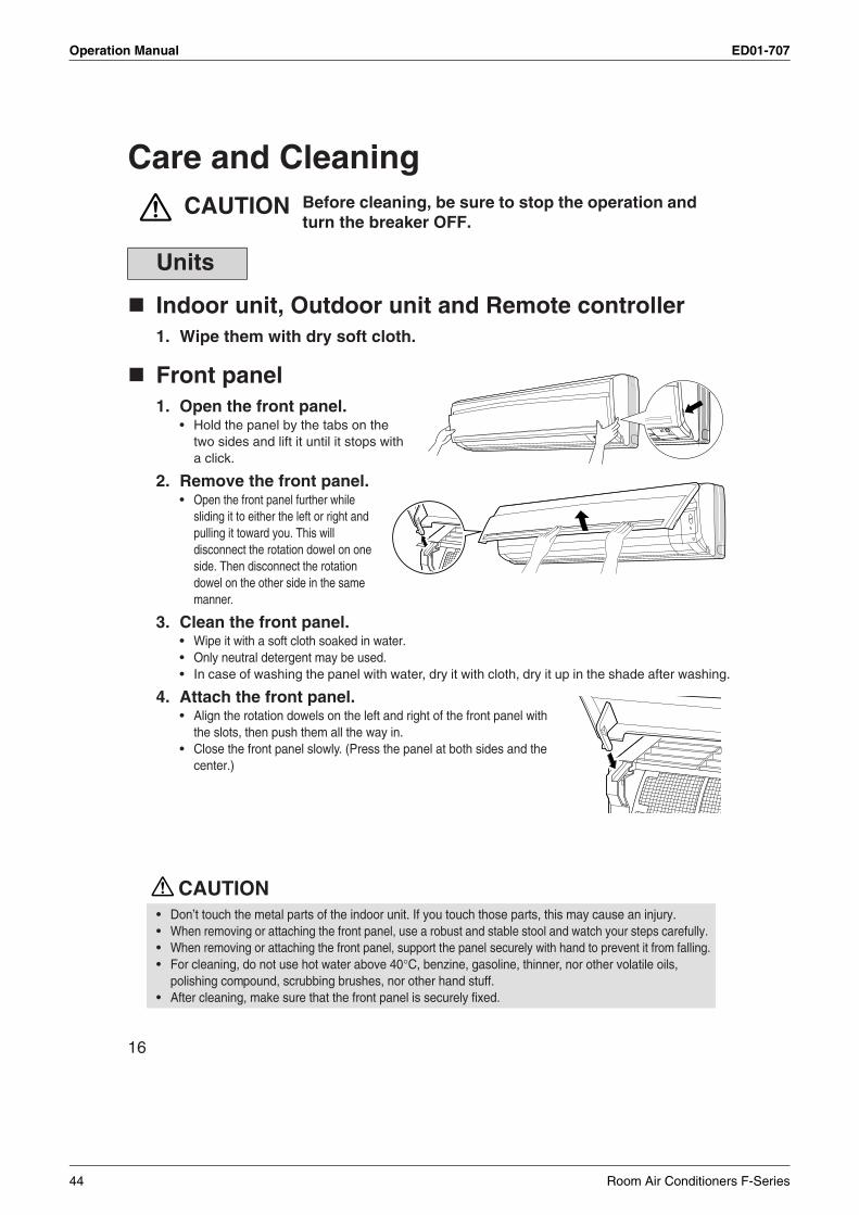
Operation Manual ED01-707
16
Care and CleaningCAUTION
Indoor unit, Outdoor unit and Remote controller1. Wipe them with dry soft cloth.
Front panel1. Open the front panel.
• Hold the panel by the tabs on the two sides and lift it until it stops with a click.
2. Remove the front panel.• Open the front panel further while
sliding it to either the left or right and pulling it toward you. This will disconnect the rotation dowel on one side. Then disconnect the rotation dowel on the other side in the same manner.
3. Clean the front panel.• Wipe it with a soft cloth soaked in water.• Only neutral detergent may be used.• In case of washing the panel with water, dry it with cloth, dry it up in the shade after washing.
4. Attach the front panel.• Align the rotation dowels on the left and right of the front panel with
the slots, then push them all the way in.• Close the front panel slowly. (Press the panel at both sides and the
center.)
CAUTION
Units
• Don’t touch the metal parts of the indoor unit. If you touch those parts, this may cause an injury.• When removing or attaching the front panel, use a robust and stable stool and watch your steps carefully.• When removing or attaching the front panel, support the panel securely with hand to prevent it from falling.• For cleaning, do not use hot water above 40°C, benzine, gasoline, thinner, nor other volatile oils,
polishing compound, scrubbing brushes, nor other hand stuff.• After cleaning, make sure that the front panel is securely fixed.
Before cleaning, be sure to stop the operation and turn the breaker OFF.
44 Room Air Conditioners F-Series
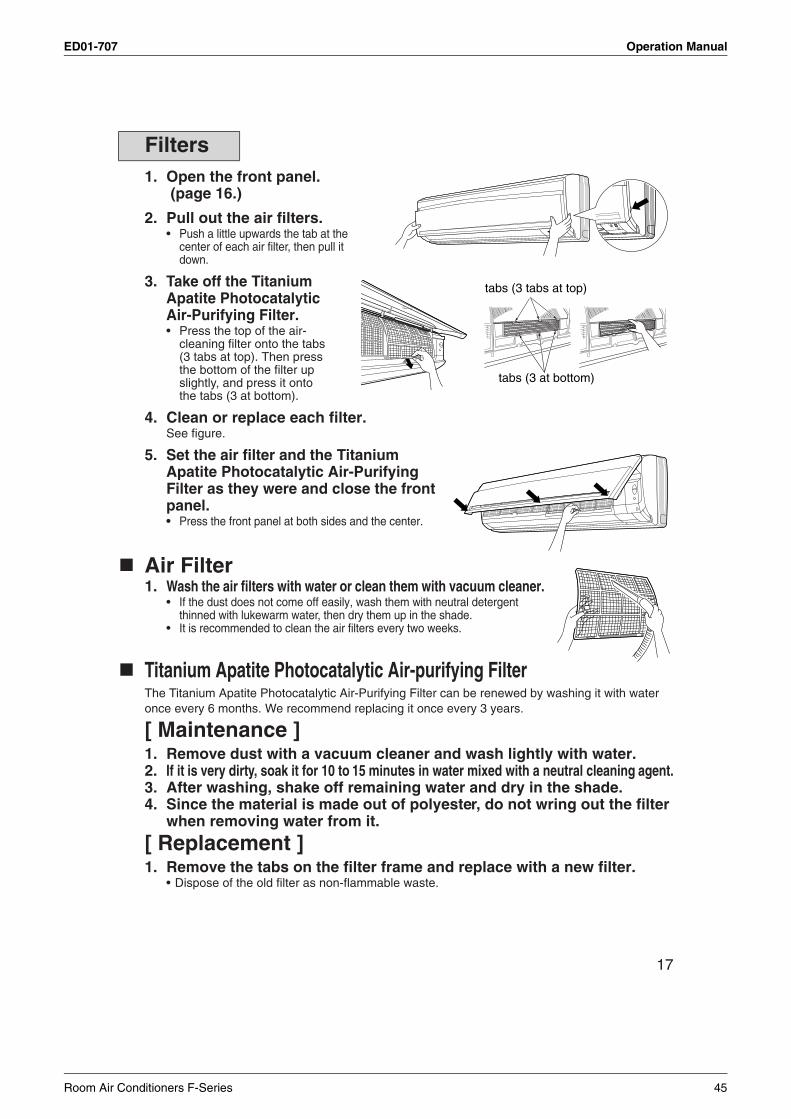
ED01-707 Operation Manual
17
1. Open the front panel. (page 16.)
2. Pull out the air filters.• Push a little upwards the tab at the
center of each air filter, then pull it down.
3. Take off the Titanium Apatite Photocatalytic Air-Purifying Filter.• Press the top of the air-
cleaning filter onto the tabs (3 tabs at top). Then press the bottom of the filter up slightly, and press it onto the tabs (3 at bottom).
4. Clean or replace each filter.See figure.
5. Set the air filter and the Titanium Apatite Photocatalytic Air-Purifying Filter as they were and close the front panel.• Press the front panel at both sides and the center.
Air Filter1. Wash the air filters with water or clean them with vacuum cleaner.
• If the dust does not come off easily, wash them with neutral detergent thinned with lukewarm water, then dry them up in the shade.
• It is recommended to clean the air filters every two weeks.
Titanium Apatite Photocatalytic Air-purifying Filter The Titanium Apatite Photocatalytic Air-Purifying Filter can be renewed by washing it with water once every 6 months. We recommend replacing it once every 3 years.
[ Maintenance ]1. Remove dust with a vacuum cleaner and wash lightly with water.2. If it is very dirty, soak it for 10 to 15 minutes in water mixed with a neutral cleaning agent.3. After washing, shake off remaining water and dry in the shade.4. Since the material is made out of polyester, do not wring out the filter
when removing water from it.
[ Replacement ]1. Remove the tabs on the filter frame and replace with a new filter.
• Dispose of the old filter as non-flammable waste.
Filters
tabs (3 tabs at top)
tabs (3 at bottom)
Room Air Conditioners F-Series 45
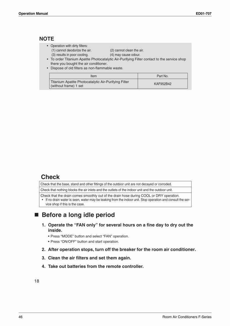
Operation Manual ED01-707
18
NOTE
Check
Before a long idle period
1. Operate the “FAN only” for several hours on a fine day to dry out the inside.• Press “MODE” button and select “FAN” operation.
• Press “ON/OFF” button and start operation.
2. After operation stops, turn off the breaker for the room air conditioner.
3. Clean the air filters and set them again.
4. Take out batteries from the remote controller.
• Operation with dirty filters: (1) cannot deodorize the air. (2) cannot clean the air. (3) results in poor cooling. (4) may cause odour.
• To order Titanium Apatite Photocatalytic Air-Purifying Filter contact to the service shop there you bought the air conditioner.
• Dispose of old filters as non-flammable waste.
Check that the base, stand and other fittings of the outdoor unit are not decayed or corroded.
Check that nothing blocks the air inlets and the outlets of the indoor unit and the outdoor unit.
Check that the drain comes smoothly out of the drain hose during COOL or DRY operation.• If no drain water is seen, water may be leaking from the indoor unit. Stop operation and consult the ser-
vice shop if this is the case.
Item Part No.
Titanium Apatite Photocatalytic Air-Purifying Filter (without frame) 1 set KAF952B42
46 Room Air Conditioners F-Series
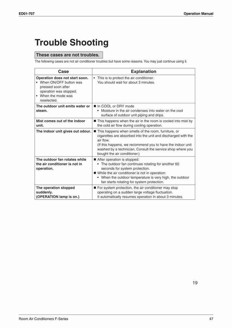
ED01-707 Operation Manual
19
Trouble Shooting
The following cases are not air conditioner troubles but have some reasons. You may just continue using it.
These cases are not troubles.
Case ExplanationOperation does not start soon.• When ON/OFF button was
pressed soon after operation was stopped.
• When the mode was reselected.
• This is to protect the air conditioner.You should wait for about 3 minutes.
The outdoor unit emits water or steam.
In COOL or DRY mode• Moisture in the air condenses into water on the cool
surface of outdoor unit piping and drips.
Mist comes out of the indoor unit.
This happens when the air in the room is cooled into mist by the cold air flow during cooling operation.
The indoor unit gives out odour. This happens when smells of the room, furniture, or cigarettes are absorbed into the unit and discharged with the air flow.(If this happens, we recommend you to have the indoor unit washed by a technician. Consult the service shop where you bought the air conditioner.)
The outdoor fan rotates while the air conditioner is not in operation.
After operation is stopped:• The outdoor fan continues rotating for another 60
seconds for system protection.While the air conditioner is not in operation:• When the outdoor temperature is very high, the outdoor
fan starts rotating for system protection.
The operation stopped suddenly.(OPERATION lamp is on.)
For system protection, the air conditioner may stop operating on a sudden large voltage fluctuation.It automatically resumes operation in about 3 minutes.
Room Air Conditioners F-Series 47
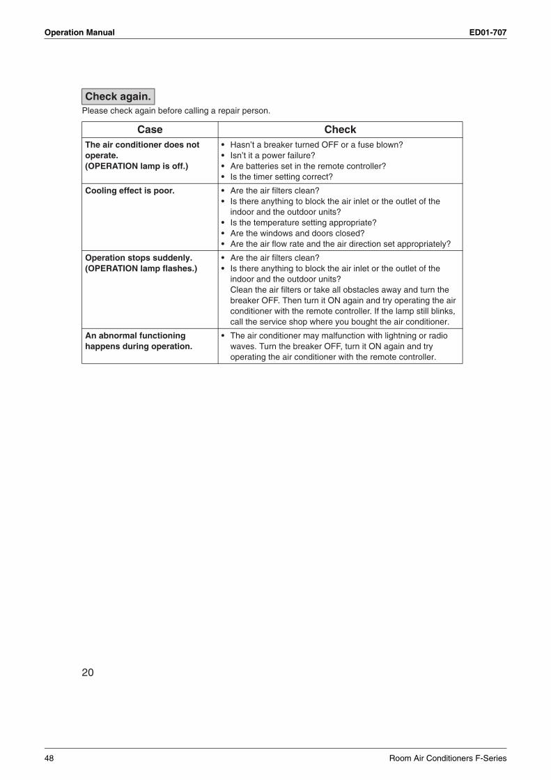
Operation Manual ED01-707
20
Please check again before calling a repair person.
Case CheckThe air conditioner does not operate.(OPERATION lamp is off.)
• Hasn’t a breaker turned OFF or a fuse blown?• Isn’t it a power failure?• Are batteries set in the remote controller?• Is the timer setting correct?
Cooling effect is poor. • Are the air filters clean?• Is there anything to block the air inlet or the outlet of the
indoor and the outdoor units?• Is the temperature setting appropriate?• Are the windows and doors closed?• Are the air flow rate and the air direction set appropriately?
Operation stops suddenly.(OPERATION lamp flashes.)
• Are the air filters clean?• Is there anything to block the air inlet or the outlet of the
indoor and the outdoor units?Clean the air filters or take all obstacles away and turn the breaker OFF. Then turn it ON again and try operating the air conditioner with the remote controller. If the lamp still blinks, call the service shop where you bought the air conditioner.
An abnormal functioninghappens during operation.
• The air conditioner may malfunction with lightning or radio waves. Turn the breaker OFF, turn it ON again and try operating the air conditioner with the remote controller.
Check again.
48 Room Air Conditioners F-Series
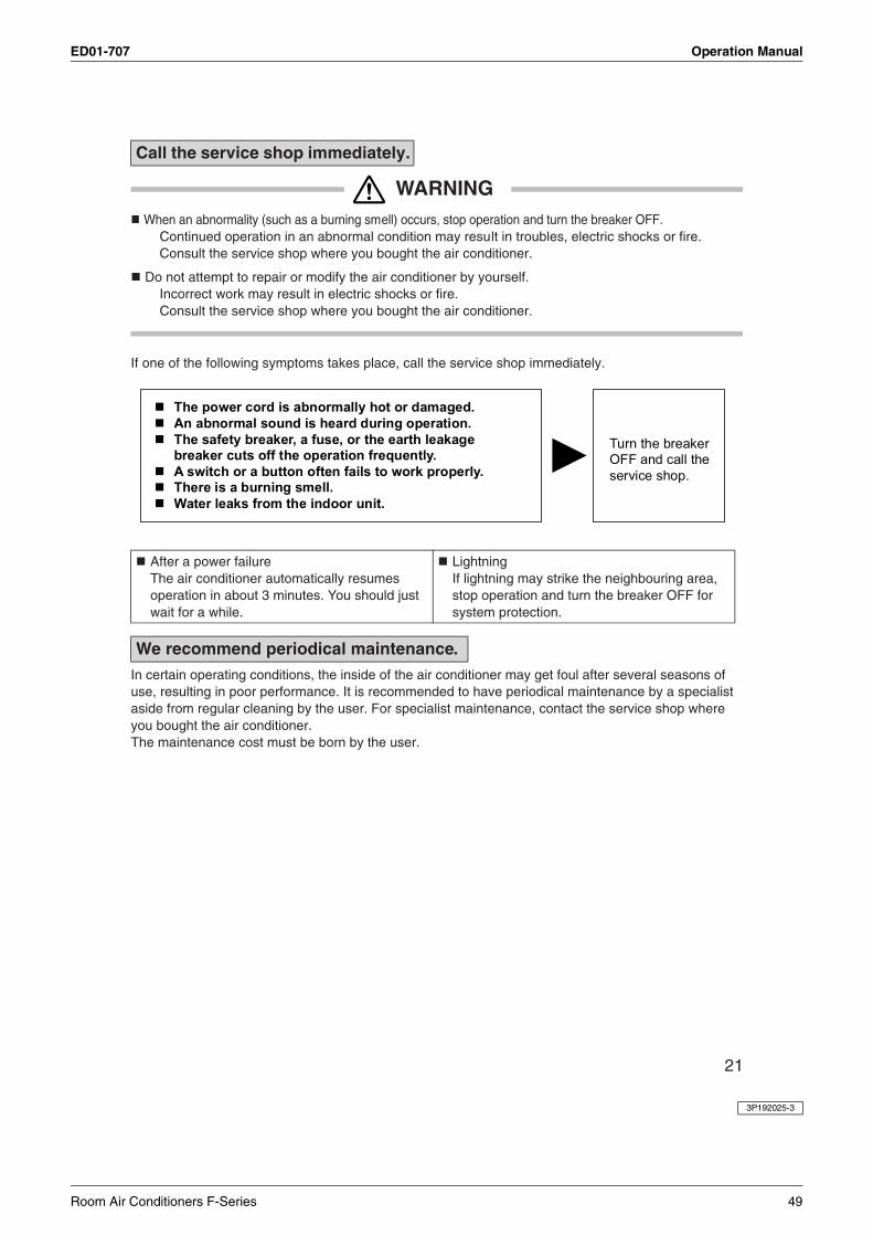
ED01-707 Operation Manual
3P192025-3
21
WARNING When an abnormality (such as a burning smell) occurs, stop operation and turn the breaker OFF.
Continued operation in an abnormal condition may result in troubles, electric shocks or fire.Consult the service shop where you bought the air conditioner.
Do not attempt to repair or modify the air conditioner by yourself.Incorrect work may result in electric shocks or fire.Consult the service shop where you bought the air conditioner.
If one of the following symptoms takes place, call the service shop immediately.
In certain operating conditions, the inside of the air conditioner may get foul after several seasons of use, resulting in poor performance. It is recommended to have periodical maintenance by a specialist aside from regular cleaning by the user. For specialist maintenance, contact the service shop where you bought the air conditioner.The maintenance cost must be born by the user.
Call the service shop
After a power failureThe air conditioner automatically resumes operation in about 3 minutes. You should just wait for a while.
LightningIf lightning may strike the neighbouring area, stop operation and turn the breaker OFF for system protection.
We . recommend periodical maintenance
immediately.
Room Air Conditioners F-Series 49
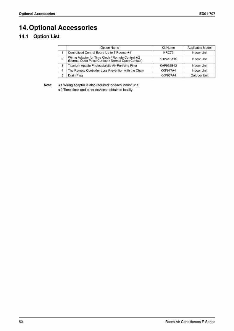
Optional Accessories ED01-707
14.Optional Accessories14.1 Option List
Note: 1 Wiring adaptor is also required for each indoor unit.2 Time clock and other devices ; obtained locally.
Option Name Kit Name Applicable Model
1 Centralized Control Board-Up to 5 Rooms 1 KRC72 Indoor Unit
2 Wiring Adaptor for Time Clock / Remote Control 2(Normal Open Pulse Contact / Normal Open Contact) KRP413A1S Indoor Unit
3 Titanium Apatite Photocatalytic Air-Purifying Filter KAF952B42 Indoor Unit
4 The Remote Controller Loss Prevention with the Chain KKF917A4 Indoor Unit
5 Drain Plug KKP937A4 Outdoor Unit
50 Room Air Conditioners F-Series
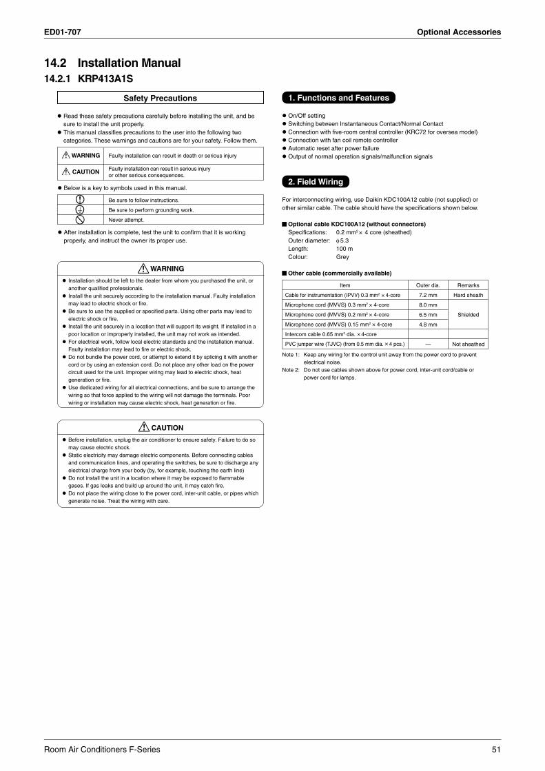
ED01-707 Optional Accessories
14.2 Installation Manual14.2.1 KRP413A1S
1. Functions and Features
On/Off settingSwitching between Instantaneous Contact/Normal ContactConnection with five-room central controller (KRC72 for oversea model)Connection with fan coil remote controllerAutomatic reset after power failureOutput of normal operation signals/malfunction signals
2. Field Wiring
For interconnecting wiring, use Daikin KDC100A12 cable (not supplied) orother similar cable. The cable should have the specifications shown below.
Optional cable KDC100A12 (without connectors)Specifications: 0.2 mm2 × 4 core (sheathed)Outer diameter: φ 5.3Length: 100 mColour: Grey
Other cable (commercially available)
Item
Cable for instrumentation (IPVV) 0.3 mm2 × 4-core
Microphone cord (MVVS) 0.3 mm2 ×
×
×
×
×
4-core
Microphone cord (MVVS) 0.2 mm2 4-core
Microphone cord (MVVS) 0.15 mm2 4-core
Intercom cable 0.65 mm2 dia. 4-core
PVC jumper wire (TJVC) (from 0.5 mm dia. 4 pcs.)
Outer dia.
7.2 mm
8.0 mm
6.5 mm
4.8 mm
—
Remarks
Hard sheath
Shielded
Not sheathed
Note 1: Keep any wiring for the control unit away from the power cord to preventelectrical noise.
Note 2: Do not use cables shown above for power cord, inter-unit cord/cable orpower cord for lamps.
Safety Precautions
Read these safety precautions carefully before installing the unit, and besure to install the unit properly.This manual classifies precautions to the user into the following twocategories. These warnings and cautions are for your safety. Follow them.
WARNING
CAUTION
Faulty installation can result in death or serious injury
Faulty installation can result in serious injuryor other serious consequences.
Below is a key to symbols used in this manual.
Be sure to follow instructions.
Be sure to perform grounding work.
Never attempt.
After installation is complete, test the unit to confirm that it is workingproperly, and instruct the owner its proper use.
WARNING
Installation should be left to the dealer from whom you purchased the unit, oranother qualified professionals.Install the unit securely according to the installation manual. Faulty installationmay lead to electric shock or fire.Be sure to use the supplied or specified parts. Using other parts may lead toelectric shock or fire.Install the unit securely in a location that will support its weight. If installed in apoor location or improperly installed, the unit may not work as intended.For electrical work, follow local electric standards and the installation manual.Faulty installation may lead to fire or electric shock.Do not bundle the power cord, or attempt to extend it by splicing it with anothercord or by using an extension cord. Do not place any other load on the powercircuit used for the unit. Improper wiring may lead to electric shock, heatgeneration or fire.Use dedicated wiring for all electrical connections, and be sure to arrange thewiring so that force applied to the wiring will not damage the terminals. Poorwiring or installation may cause electric shock, heat generation or fire.
CAUTION
Before installation, unplug the air conditioner to ensure safety. Failure to do somay cause electric shock.Static electricity may damage electric components. Before connecting cablesand communication lines, and operating the switches, be sure to discharge anyelectrical charge from your body (by, for example, touching the earth line)Do not install the unit in a location where it may be exposed to flammablegases. If gas leaks and build up around the unit, it may catch fire.Do not place the wiring close to the power cord, inter-unit cable, or pipes whichgenerate noise. Treat the wiring with care.
Room Air Conditioners F-Series 51
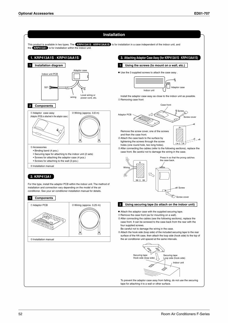
Optional Accessories ED01-707
Installation
This product is available in two types. The KRP413A1S · KRP413AA1S is for installation in a case independent of the indoor unit, andthe KRP413A1 is for installation within the indoor unit.
1. KRP413A1S · KRP413AA1S
1 Installation diagram
Indoor unit PCB
Adaptor case
wiringLocal wiring or power cord, etc.
S21
2 Components
Adaptor case assy Wiring (approx. 0.8 m)(Adaptor (PCB) is attached in the adaptor case.)
Accessories• Binding band (4 pcs.)• Securing tape for attaching to the indoor unit (2 sets)• Screws for attaching the adaptor case (4 pcs.)• Screws for attaching to the wall (3 pcs.)
Installation manual
2. KRP413A1
For this type, install the adaptor PCB within the indoor unit. The method ofinstallation and connection vary depending on the model of the airconditioner. See your air conditioner installation manual for details.
1 Components
Adaptor PCB Wiring (approx. 0.25 m)
Installation manual
3. Attaching Adaptor Case Assy (for KRP413A1S · KRP413AA1S)
1 Using the screws (to mount on a wall, etc.)
Use the 3 supplied screws to attach the case assy .
Indoor unitAdaptor case
Install the adaptor case assy as close to the indoor unit as possible.Removing case front
Adaptor PCB
Case front
Screw
Screw cover
Remove the screw cover, one of the screwsand then the case front.Attach the case back to the surface bytightening the screws through the screwholes (one round hole, two long holes).After connecting the cables (refer to the following sections), replace thecase front. Be careful not to damage the wiring in the case.
Wiring
Press in so that the prong catches the case back.
Screw
Screw cover
2 Using securing tape (to attach on the indoor unit)
Attach the adaptor case with the supplied securing tape.Remove the case front (as for mounting on a wall).After connecting the cables (see the following sections), replace thecase front. It can be screwed to the case back from the rear with thefour supplied screws.Be careful not to damage the wiring in the case.Attach the hook side (loop side) of the included securing tape to the rearsurface of the HA case, then attach the loop side (hook side) to the top ofthe air conditioner unit spaced at the same intervals.
Securing tape Hook side (loop side)
Securing tape Loop side (hook side)
Indoor unit
To prevent the adaptor case assy from falling, do not use the securingtape for attaching it to a wall or other surface.
52 Room Air Conditioners F-Series
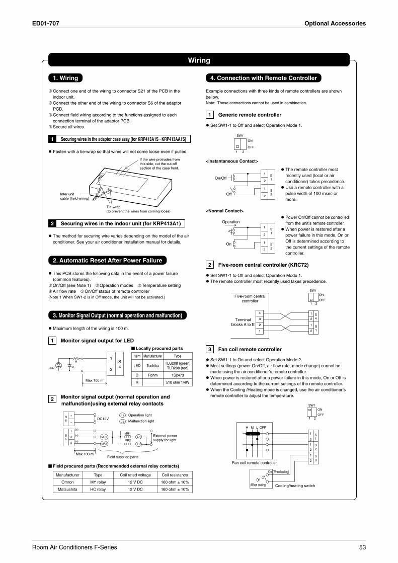
ED01-707 Optional Accessories
Wiring
1. Wiring
Connect one end of the wiring to connector S21 of the PCB in theindoor unit.Connect the other end of the wiring to connector S6 of the adaptorPCB.Connect field wiring according to the functions assigned to eachconnection terminal of the adaptor PCB.Secure all wires.
1 Securing wires in the adaptor case assy (for KRP413A1S · KRP413AA1S)
Fasten with a tie-wrap so that wires will not come loose even if pulled.
Inter unit cable (field wiring)
Tie-wrap (to prevent the wires from coming loose)
If the wire protrudes from this side, cut the cut-off section of the case front.
2 Securing wires in the indoor unit (for KRP413A1)
The method for securing wire varies depending on the model of the airconditioner. See your air conditioner installation manual for details.
2. Automatic Reset After Power Failure
This PCB stores the following data in the event of a power failure(common features).On/Off (see Note 1) Operation modes Temperature settingAir flow rate On/Off status of remote controller
(Note 1 When SW1-2 is in Off mode, the unit will not be activated.)
3. Monitor Signal Output (normal operation and malfunction)
Maximum length of the wiring is 100 m.
1 Monitor signal output for LED
LED D
R1
2
S4
Max 100 m
2 Monitor signal output (normal operation and malfunction)using external relay contacts
DC12V
MR1
MR2L 1
2L
MR1
MR2
L 1
2L
: Operation light
: Malfunction light
+
(+)
(–)
(–)
–
1
2
3
S8
S5
Max 100 mField supplied parts
External power supply for light
Field procured parts (Recommended external relay contacts)
Manufacturer Type Coil rated voltage Coil resistance
Omron MY relay 12 V DC 160 ohm ± 10%
Matsushita HC relay 12 V DC 160 ohm ± 10%
4. Connection with Remote Controller
Example connections with three kinds of remote controllers are shownbellow.Note: These connections cannot be used in combination.
1 Generic remote controller
Set SW1-1 to Off and select Operation Mode 1.
SW1
ON
OFF1 2
<Instantaneous Contact>
1
2
1
2
S2
S1On/Off
Off
<Normal Contact>
1
2
1
2
S1
S2
Operation
On
2 Five-room central controller (KRC72)
Set SW1-1 to Off and select Operation Mode 1.The remote controller most recently used takes precedence.
Five-room centralcontroller
Terminalblocks A to E
1
2
3
4 1
2
1
2
1 2
SW1ON
OFF
S4
S1
3 Fan coil remote controller
Set SW1-1 to On and select Operation Mode 2.Most settings (power On/Off, air flow rate, mode change) cannot bemade using the air conditioner’s remote controller.When power is restored after a power failure in this mode, On or Off isdetermined according to the current settings of the remote controller.When the Cooling /Heating mode is changed, use the air conditioner’sremote controller to adjust the temperature.
1 2
SW1ON
OFF
S1
1
2
1
2
1
2
S2
S3
H M L OFF
Fan coil remote controller
Off(When cooling)
On (When heating)
Cooling/heating switch
Locally procured parts
Item Manufacturer Type
LED ToshibaTLG208 (green)
TLR208 (red)
D Rohm 1S2473
R 510 ohm 1/4W
The remote controller mostrecently used (local or airconditioner) takes precedence.Use a remote controller with apulse width of 100 msec ormore.
Power On/Off cannot be controlledfrom the unit’s remote controller.When power is restored after apower failure in this mode, On orOff is determined according tothe current settings of the remotecontroller.
Room Air Conditioners F-Series 53
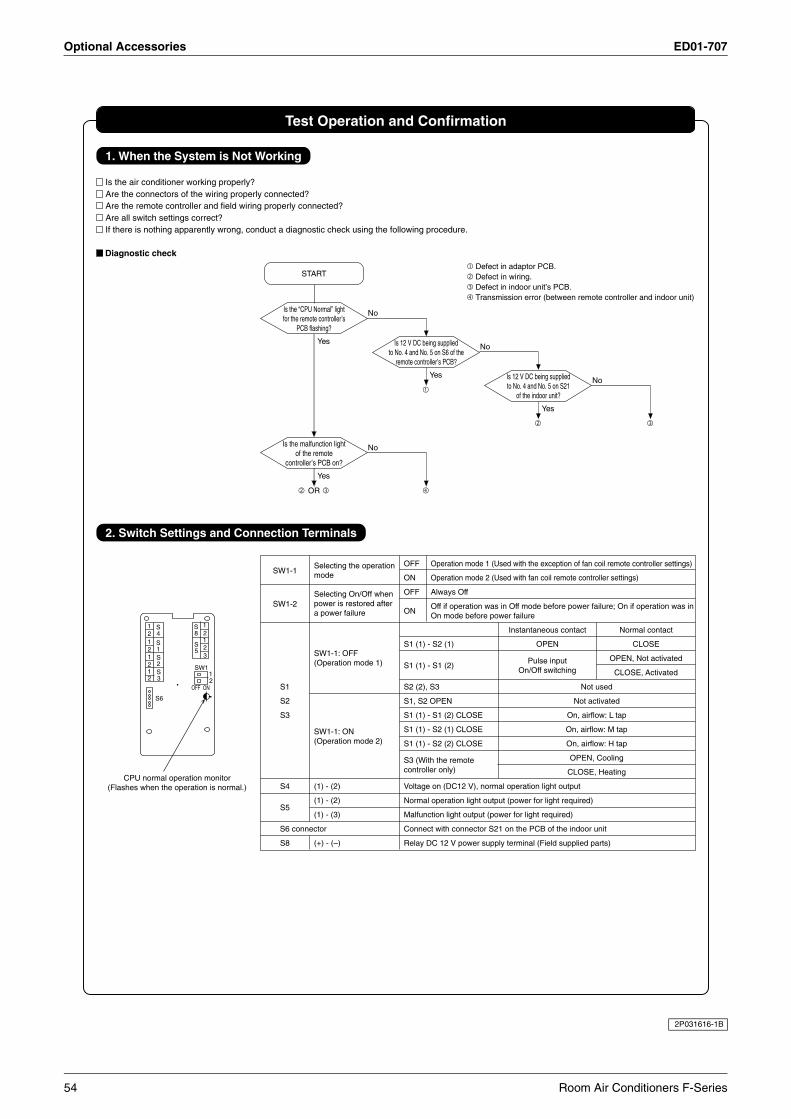
Optional Accessories ED01-707
Test Operation and Confirmation
1. When the System is Not Working
Is the air conditioner working properly?Are the connectors of the wiring properly connected?Are the remote controller and field wiring properly connected?Are all switch settings correct?If there is nothing apparently wrong, conduct a diagnostic check using the following procedure.
Diagnostic check
2. Switch Settings and Connection Terminals
12121212
12
3
S8
12
S4
S1S2S3
S5
12
SW1
OFF ON
S6
CPU normal operation monitor(Flashes when the operation is normal.)
SW1-1
SW1-2
S1
S2
S3
S4
S5
S6 connector
S8
Selecting the operationmode
Selecting On/Off whenpower is restored aftera power failure
SW1-1: OFF(Operation mode 1)
SW1-1: ON(Operation mode 2)
(1) - (2)
(1) - (2)
(1) - (3)
(+) - (–)
OFF Operation mode 1 (Used with the exception of fan coil remote controller settings)
ON Operation mode 2 (Used with fan coil remote controller settings)
OFF Always Off
ONOff if operation was in Off mode before power failure; On if operation was inOn mode before power failure
Instantaneous contact Normal contact
S1 (1) - S2 (1) OPEN CLOSE
S1 (1) - S1 (2)Pulse input OPEN, Not activated
On/Off switching CLOSE, Activated
S2 (2), S3 Not used
S1, S2 OPEN Not activated
S1 (1) - S1 (2) CLOSE On, airflow: L tap
S1 (1) - S2 (1) CLOSE On, airflow: M tap
S1 (1) - S2 (2) CLOSE On, airflow: H tap
S3 (With the remote OPEN, Cooling
controller only) CLOSE, Heating
Voltage on (DC12 V), normal operation light output
Normal operation light output (power for light required)
Malfunction light output (power for light required)
Connect with connector S21 on the PCB of the indoor unit
Relay DC 12 V power supply terminal (Field supplied parts)
START
Is the “CPU Normal” lightfor the remote controller’s
PCB flashing?
No
Is 12 V DC being suppliedto No. 4 and No. 5 on S6 of the
remote controller’s PCB?
No
Yes Is 12 V DC being suppliedto No. 4 and No. 5 on S21
of the indoor unit?
No
Yes
Is the malfunction lightof the remote
controller’s PCB on?
No
Yes
OR
Yes
Defect in adaptor PCB.Defect in wiring.Defect in indoor unit’s PCB.Transmission error (between remote controller and indoor unit)
2P031616-1B
54 Room Air Conditioners F-Series
Specifications, designs and other content appearing in this brochure are current as of January 2007 but subject to change without notice.ED 01-707Printed in Japan 01/2007 B AK