ECS G24 ALL-IN-ONE PC CHASSIS INTEGRATION WITH THE GIGABYTE GA … · CHASSIS INTEGRATION WITH THE...
2
ECS G24 ALL-IN-ONE PC CHASSIS INTEGRATION WITH THE GIGABYTE GA-Q87TN DESKTOP BOARD Connect the HDD and ODD SATA connectors. Clip the speaker unit to the chassis by lifting it into place. Ensure that the back chassis cover has been replaced prior to clipping on the speaker unit. Clip the audio cable connector to the chassis before connecting the speaker unit to the chassis. 10. Connecting the SATA Connectors 11. Connecting the Audio Cable Connector 12. Replacing the Speaker Unit Disconnect the speakers by pushing down on clips on either side of the bottom of the chassis and remove the speaker section. Place the HDD into the mounting bracket and connect all SATA connectors, as pictured. 1. Disconnecting the Speaker Unit To remove the back panel, insert a screwdriver into the corner flange and lever gently to release catch. This needs to be done on either side of the chassis. 2. Removing the Back Panel 3. Placing the HDD in the Mounting Bracket Secure the HDD to the mounting bracket by fastening the retention screws on the underside of the bracket. To remove the HDD carrier, simply pull back the retention mechanism. To install the optional HDD in the ODD position, insert the HDD into the carrier by sliding it into the bracket. 4. Securing the HDD to the Mounting Bracket 5. Installing the Optional HDD 6. Removing the HDD Carrier
Transcript of ECS G24 ALL-IN-ONE PC CHASSIS INTEGRATION WITH THE GIGABYTE GA … · CHASSIS INTEGRATION WITH THE...
ECS G24 ALL-IN-ONE PC CHASSIS INTEGRATION WITH THE GIGABYTE GA-Q87TN DESKTOP BOARD
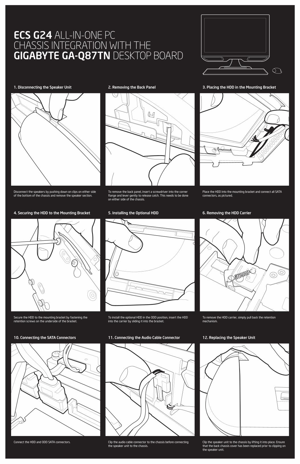
Connect the HDD and ODD SATA connectors. Clip the speaker unit to the chassis by lifting it into place. Ensure that the back chassis cover has been replaced prior to clipping on the speaker unit.
Clip the audio cable connector to the chassis before connecting the speaker unit to the chassis.
10. Connecting the SATA Connectors 11. Connecting the Audio Cable Connector 12. Replacing the Speaker Unit
Disconnect the speakers by pushing down on clips on either side of the bottom of the chassis and remove the speaker section.
Place the HDD into the mounting bracket and connect all SATA connectors, as pictured.
1. Disconnecting the Speaker Unit
To remove the back panel, insert a screwdriver into the corner flange and lever gently to release catch. This needs to be done on either side of the chassis.
2. Removing the Back Panel 3. Placing the HDD in the Mounting Bracket
Secure the HDD to the mounting bracket by fastening the retention screws on the underside of the bracket.
To remove the HDD carrier, simply pull back the retention mechanism.
To install the optional HDD in the ODD position, insert the HDD into the carrier by sliding it into the bracket.
4. Securing the HDD to the Mounting Bracket 5. Installing the Optional HDD 6. Removing the HDD Carrier

FPD - 19V
1 2 3
LCD - 5V
1 2 3
5 6
7
77
7
8
9 10
11
12 13 13 14 15 17 17 19 2021
22
23 24
2526
27282930
3132
33
1816
43
21
1. LVDS
2. LCD Panel SW
3. Front Panel
4. CPU Fan
5. SATA Power
6. DDR3 SP DIMM
7. SATA III Ports
8. Single USB Header
9. USB 3 Connect
10. Half Length Mini PCI-e Slot
11. Internal ATX 19V Connector
12. 19V DC In
13. 2x GbE LAN Ports
14. Display Port
15. HDMI
16. COM1
17. USB 3
18. LPT
19. Speaker Out
20. Mic In
21. Speaker
22. FP Audio
23. DMIC
24. CLR CMOS
25. Full Length Mini PCI-e / mSATA
26. PCI-e 4X
27. 2 x Single USB Headers
28. Dual USB 2 Header
29. FPD
30. BL_SW
31. WFLED
32. LCD PWR
33. FPD PWR
LCD INTEGRATION NOTES
GENERAL INTEGRATION NOTES
GIGABYTE GA-Q87TN DESKTOP BOARD OVERVIEW
1. Inserting the LVDS Connector 2. Checking Jumper Settings 3. Configuring the BIOS
1. Placing the Thermal Retention Mechanism 2. Placing the Thermal Tab 3. Inserting the Desktop Board
4. SATA and DATA 5. Single USB Connection
1
2
When inserting the LVDS Connector, confirm correct alignment. Once in, never remove the cable by “pulling on the wires”, as this could permanently damage the cable.
Confirm that this jumper settings for the Backlight Inverter and Front Panel voltage are correct for the inverter and the board being integrated.
Ensure LVDS Cable is ConnectedNavigate to ChipsetSelect Enable for LVDS Control FunctionSelect M215HGE-L10/M240Q002 for Panel Type
Check that the thermal retention mechanism is in place before installing the desktop board.
Once the thermal retention mechanism is in place, secure the thermal pad as above.
When installing the desktop board, it may help to locate the power connection on the desktop board with the IO shield first and then “swivel” the board in. Check that the ports on the desktop board connect with the IO shield contacts.
The SATA power cable provides power for the HDD and ODD. Where a “single” USB connection is connected to a dual USB header, confirm that the “red” cable is aligned to the pins closest to PIN 1 (white marking at the base). It is possible to connect two single USB connections to a dual port USB header in this manner.
6. Wireless Connection
For Wireless-N & Wireless-AC maximum bandwidth potential, ensure that both wireless antennae are connected to the wireless adapter.
Navigate to Chipset
Select Enable for LVDS Control Function
Select M215HGE-L10/M240Q002 for Panel Type