ECOLE DE TECHNOLOGIE SUPERIEURE UNIVERSITE ...TRAN, Nguyen Duy Phuong RESUME Les presse-plieuses...
96
ECOLE DE TECHNOLOGIE SUPERIEURE UNIVERSITE DU QUEBEC THESIS PRESENTED TO ECOLE DE TECHNOLOGIE SUPERIEURE IN PARTIAL FULFILLMENT OF THE REQUIREMENTS FOR THE DEGREE OF DOCTOR OF PHILOSOPHY Ph.D. BY Nguyen Duy Phuong TRAN DEVELOPMENT OF A FLEXIBLE PROTECTIVE SYSTEM FOR PRESS-BRAKES USING VISION MONTREAL, MARCH 26, 2009 © Copyright 2009 reserved by Nguyen Duy Phuong Tran
Transcript of ECOLE DE TECHNOLOGIE SUPERIEURE UNIVERSITE ...TRAN, Nguyen Duy Phuong RESUME Les presse-plieuses...

ECOLE DE TECHNOLOGIE SUPERIEURE UNIVERSITE DU QUEBEC
THESIS PRESENTED TO ECOLE DE TECHNOLOGIE SUPERIEURE
IN PARTIAL FULFILLMENT OF THE REQUIREMENTS FOR THE DEGREE OF DOCTOR OF PHILOSOPHY
Ph.D.
BY Nguyen Duy Phuong TRAN
DEVELOPMENT OF A FLEXIBLE PROTECTIVE SYSTEM FOR PRESS-BRAKES USING VISION
MONTREAL, MARCH 26, 2009
© Copyright 2009 reserved by Nguyen Duy Phuong Tran

THIS THESIS H A S BEEN EVALUATED
BY THE FOLLOWING BOARD OF EXAMINERS:
Mr. Anh Dung Ngo, Ph.D.,Thesis Supervisor Department of Mechanical Engineering at Ecole de Technologie Superieure
Mr. Louis Lamarche, Ph.D., Thesis Co-supervisor Department of Mechanical Engineering at Ecole de Technologie Superieure
Mr. Phieu Le-Huy, Ph.D., President of the Board of Examiners Department of Electrical Engineering at Ecole de Technologie Superieure
Mrs. Sylvie Nadeau, Ph.D., Examiner Department of Mechanical Engineering at Ecole de Technologie Superieure
Mr. Pierre C. Dessureault, Ph.D., External Examiner Department of Industrial Engineering at Universite du Quebec a Trois-Rivieres
THIS THESIS WAS PRESENTED AND DEFENDED
BEFORE A BOARD OF EXAMINERS AND PUBLIC
F E B U A R Y 1 7 , 2 0 0 9
AT ECOLE DE TECHNOLOGIE SUPERIEURE

ACKNOWLEDGEMENT
I would like to thank my thesis supervisors, Prof Anh Dung Ngo, and Prof Louis Lamarche,
for their direction and support.
My thanks to the committee members, Prof Phieu Le-Huy, Prof Sylvie Nadeau, and Prof
Pierre C. Dessureault, for their effort in reviewing this work.
I would like to thank Tran Cuong, Nguyen Thi Giau, Le Thi Anh Tuyet, and Tran Thi Cue
Phuong, for always believing in me, and for supporting me through the difficult moments.
I would like to thank the chiefs of the laboratory of safety, Prof Sylvie Nadeau, of the
laboratory of vision, Prof Richard Lepage and of the laboratory of measurement, Prof
Souheil Antoine Tahan, because most of my experiments were performed in these
laboratories.
I would like to thank Nguyen Thi Tuyet Nhung, Christine Galvin, Michel Drouin, Patrick
Sheridan, Alexandre Vigneault, and Serge Plamondon, who gave me a lot of assistance.
Finally, I would like to thank everybody that I could not mention personally one by one.

DEVELOPPEMENT D'U N SYSTEME FLEXIBLE DE PROTECTION POUR LES
PRESSE-PLIEUSES PA R LA VISION
TRAN, Nguyen Duy Phuong
RESUME
Les presse-plieuses sont utilisees dans la plupart des ateliers de fabrication pour le phage, le formage, le redressage, le poin9onnage et le decoupage. Malheureusement, ces machines polyvalentes ont cause de nombreux accidents sur les travailleurs qui devront tenir la piece ou de mettre les mains dans les zones dangereuses afm de maintenir le rythme de production.
II est connu que le mouvement du belier hydraulique dans les presse-plieuses peut etre arrete a tout moment pendant le fonctionnement ce qui est impossible dans le cas des presse-plieuses mecaniques. Pour cette raison, seul le developpement d'un systeme de protection pour presse-plieuse hydraulique est recommande. II a egalement ete observe que la plupart des systemes existants avaient une zone d'interdiction fixe, qui arrete la presse-plieuse hydraulique au moment oil les mains du travailleur y entrent. Ces systemes de protection sont incapables de distinguer le mouvement des mains des travailleurs, qui sont diriges vers la zone de I'outil de coupe ou vers I'exterieur de cette zone dangereuse. II est done trop restreint de repondre aux besoins de production. Afin d'ameliorer la flexibilite du systeme de protection, il est necessaire de developper un nouveau systeme. Cette these presente le developpement d'un systeme flexible de protection en tenant compte du mouvement de la main du travailleur.
La solution innovante consiste a generer une zone d'interdiction flexible dont les dimensions et la forme dependent de la vitesse instantanee du point inspecte, du temps d'arret de la machine et du temps de calcul du processus. Le mouvement instantane d'un point inspecte sur la main du travailleur est depiste par des cameras distribuant des differentes vues. La machine sera arretee immediatement chaque fois que le point inspecte est entre dans la zone flexible d'interdiction. L'interference entre le point inspecte et la zone flexible d'interdiction est determinee par le vecteur traversable dans I'espace.
Deux approches concernant le nombre de points inspectes sont presentees. Le point inspecte sur la main du travailleur est un point unique et virtuel dans la premiere approche, tandis qu'au moins trois points virtuels sont dans la deuxieme approche. L'objectif de la premiere approche a pour but de reduire le temps de processus tandis que celui de la deuxieme approche a pour but d'augmenter la precision de posifionnement des points.
Le travail presente dans cette these prouve que le principe d'etablissement de la zone flexible a I'aide de la technologie de vision pour la protection des mains de I'operateur de presses-plieuses est realisable.
Mots-Cles: Systeme flexible de protection, Zone d'interdiction flexible, Presses-plieuses, Vision, Point unique, Multipoints.

DEVELPOMENT OF A FLEXIBLE PROTECTIVE SYSTEM FOR PRESS-BRAKE S
USING VISION
TRAN, Nguyen Duy Phuong
ABSTRACT
Press-brakes are used in most manufacturing workshops for bending, forming, straightening, punching and trimming. Unfortunately, these versatile machines cause many accidents to workers, who in many cases, must hold the work piece too close to the dies, or must put their hands within the dangerous zones in order to keep up with the rate of production.
It is known that the movement of the ram in hydraulic press-brakes can be stopped instantaneously at any time during the process. For this reason, only a protective system for hydraulic press-brakes is recommended. It has also been observed that most existing systems have a fixed interdiction volume, provoking stoppage of the press-brake whenever the hands of the worker enter this area. These protective systems cannot distinguish motions which are directed towards entering the cutting zone from motions aiming at the exterior of this dangerous zone. They are therefore too restrictive to meet production needs. In order to improve the flexibility of the protective system, it is necessary to develop a new one. This thesis presents the development of a flexible protective system, taking the motion of the worker's hands into account.
The proposed innovative solution consists of generating a flexible interdiction zone, whose dimensions and shape depend on the instantaneous velocity of the inspected point, the machine stopping time, and the calculation time of the processing loop. The instantaneous motion of an inspected point on the worker's hand is tracked using camera sets distributing on the different views. The machine is stopped whenever the inspected point interferes with the flexible interdiction zone. The interference between the inspected point and the flexible interdiction zone is verified using the spatial traversability vector.
Two approaches relating to the number of inspected points are presented. The inspected point on the worker's hand is a single virtual point in the first principle, whereas several virtual points are in the second principle. The first approach deals with the processing time, while the second is aimed at improving the precision.
The work presented in this thesis proves that the principle of the flexible protective zone using vision technology is realizable to protect the worker's hands.
Keywords: Flexible protective system, Flexible interdiction zone. Press-brakes, Vision, Single-point, Multi-point.

TABLE OF CONTENTS
Page
INTRODUCTION
CHAPTER 1 LITERATURE REVIEW 5 1.1 The hydraulic press-brake 5 1.2 The dangerous zone of the press-brake 5 1.3 The existing protective systems 6 1.4 The research of the protective system using vision 10 1.5 The related works of localization using vision 11 1.6 Conclusion 11
CHAPTER 2 THE FLEXIBLE PROTECTIVE SYSTEM WITH SINGLE-POINT INSPECTION 14
2.1 Principle and definitions 14 2.1.1 Principle 14 2.1.2 Definitions 14
2.2 Algorithm 16 2.2.1 Multi-view extraction process 16 2.2.2 Determination of the center of the bracelet image 18 2.2.3 Calculation of the kinematic parameters 20
2.2.3.1 Determination of the location of the bracelet center 21 2.2.3.2 Calculation of the instantaneous velocity of the bracelet center 23
2.2.4 Establishment of the flexible interdiction zone 24 2.2.4.1 Dimensions of the flexible interdiction zone 24 2.2.4.2 Shape of the flexible interdiction zone 25 2.2.4.3 Example 25
2.2.5 Verification of the interference between the inspected point and the flexible interdiction zone 27 2.2.5.1 The spatial traversability vector 27 2.2.5.2 Example 28
2.3 Experimental 30 2.3.1 Test bench 30
2.3.1.1 The emitting bracelet 31 2.3.1.2 The stereo head 31 2.3.1.3 Image acquisition 32 2.3.1.4 Calibration of the cameras 33 2.3.1.5 Processing time 33
2.3.2 Ability to overcome the occultation problem by using the two-view system 33
2.3.3 The extraction process 35 2.4 Results 36
2.4.1 Investigation of the error of positioning 36

VII
2.4.1.1 Calculation of the bracelet center using the vision system 37 2.4.1.2 Measurement of the bracelet center using coordinate measuring
machine 38 2.4.1.3 The difference between the measured position and the calculated
position of the bracelet center 38 2.4.2 Investigation of the error of magnitude of the velocity vector 39
2.5 Conclusion 41
CHAPTER 3 THE FLEXIBLE PROTECTIVE SYSTEM WITH MULTI-POfNT INSPECTION 42
3.1 Principle and definitions 42 3.1.1 Principle 42 3.1.2 Definitions 42
3.2 Algorithm 44 3.2.1 Multi-view extraction process 44 3.2.2 Calculation of kinematic parameters 45 3.2.3 Establishment of the flexible interdiction zone 46 3.2.4 Verification of the interference between the inspected point and
the flexible interdiction zone 46 3.3 Experimental 47
3.3.1 Test bench 47 3.3.1.1 The processing time 48
3.3.2 The extraction process 48 3.4 Results 49
3.4.1 Investigation of the error of positioning 49 3.4.2 Investigation of the error of the velocity magnitude 50
3.5 Conclusion 52
CONCLUSION 53
APPENDIX I SHAPES OF THE FLEXIBLE INTERDICTION ZONE 56
APPENDIX II SOURCE CODE OF FUNCTIONS 57
BIBLIOGRAPHY 83

LIST OF TABLES
Page
Table 1.1 Statistics for accidents involving compensation in Quebec
fi-om 1989 to 1994 1
Table 1.2 The evolution of the protection methods 12
Table 2.1 The average acquisition time 33
Table 2.2 The average time needed for the extraction process in various image resolutions 36
Table 2.3 The difference between the coordinates measured by the coordinate measuring machine and the results obtained by the vision method in various distances and resolutions 39
Table 2.4 The difference between the velocity set on the linear positioner and the results obtained by the vision system at various distances with a resolufion of 640x480 pixels 41
Table 3.1 The difference between the coordinates measured by the coordinate measuring machine and the results obtained by the vision system in various distances and resolutions 50
Table 3.2 The difference between the velocity magnitude of the emitting sphere set on the positioner and the resuhs obtained using the vision system in various distances with the resolution of 640x480 pixels 51
LIST OF FIGURES
Page
Figure 1.1 The hydraulic press-brake 5
Figure 1.2 The contact surface of the tool 6
Figure 1.3 Press-brake fixed guard 6
Figure 1.4 Press-brake interlocking guard 7
Figure 1.5 Press-brake distance bar trip guard 8
Figure 1.6 Pullback device on press-brake 8
Figure 1.7 Photoelectric presence-sensing device on press-brake 9
Figure 1.8 Laser sensing system 9
Figure 1.9 Vision-based safety equipment 10
Figure 1.10 Risk of hand injury in cases involving working with small pieces
or trays using press-brakes 12
Figure 2.1 The operational principle of the proposed system 15
Figure 2.2 Dimensions of the initial interdiction zone 15
Figure 2.3 Data-flow model of the global process 17
Figure 2.4 Calculation of the 3D coordinates of the bracelet center 23
Figure 2.5 Determination of the flexible interdiction zone 24
Figure 2.6 The initial interdiction zone 26
Figure 2.7 The shape of the flexible interdiction zone 26
Figure 2.8 The normal vector 28
Figure 2.9 The flexible interdiction zone and the normal vector of the plane 1 29
Figure 2.10 The test bench equipped with a flexible protective system using multi-view vision 30
Figure 2.11 The emitting bracelet 31
X
Figure 2.12 The stereo head 32
Figure 2.13 Connection of a stereo head with a computer 32
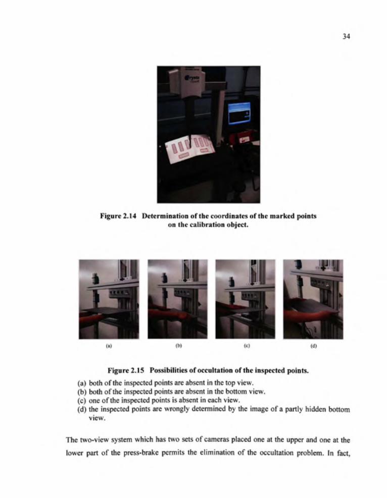
Figure 2.14 Determination of the coordinates of the marked points
on the calibration object 34
Figure 2.15 Possibilities of occultation of the inspected points 34
Figure 2.16 The extraction process 35
Figure 2.17 The experimental set-up for the assessment of the error
of the present vision method 36
Figure 2.18 The coordinates of the bracelet image centers 37
Figure 2.19 Measurement of the bracelet center using CMM 38
Figure 2.20 The experimental set-up for the assessment the error
of the velocity magnitude of the bracelet center 40
Figure 3.1 The inspected points on the worker's hand 42
Figure 3.2 Dimensions of the initial interdiction zone 43
Figure 3.3 Data-flow model of the global process for the multi-points
inspection approach 45
Figure 3.4 The modified test bench 47
Figure 3.5 The emitting spheres 48
Figure 3.6 The extraction process 48
Figure 3.7 The experimental set-up for assessment of the error of positioning 49
Figure 3.8 The experimental set-up for the assessment of the error of the velocity magnitude of the sphere 51

LIST OF A B R E V I A T I O N S
2D Two dimensions 3D Three dimensions ANSI American national standards institute CMM Coordinate measuring machine OHCI Open host controller interface PC Personal computer

INTRODUCTION
Press-brakes are used in many factories due to their versatility. They can be used to bend,
form, straighten pieces, punch holes, and trim edges. However, it has been observed that,
during operations, the operator's hands are constantly in the proximity of the hazardous zone
[1]. Table 1.1 presents the number of compensated accidents in Quebec from 1989 to 1994
reported by the Commission de la Sante et de la Securite du Travail du Quebec (CSST) [1].
A study published by this governmental agency showed that the percentage of accidents
involving the upper limb counted for 35% (approximately 12000 cases) of the total accidents
reported during the period of time fi-om 1979 to 1982 [2]. F. Beauchemin and S. Guertin [3]
in their study of 184 accidents in five manufactures confirmed that 15% of the accidents were
related to press-brakes. Most of the victims were operators (78%), and arms and hands were
involved in 67% of the accidents. This evidence shows that the use of press-brakes can be
hazardous to the operator's hands.
Table 1.1 Statistics for accidents involving compensation in Quebec from 1989 to 1994.
From [1] (1997, pp. 2)
Year
1989
1990
1991
1992
1993
1994
Number of accidents
8947
7450
6699
6031
5684
4725
Death
1
1
5
3
3
1
Much research has been done and many protective systems have been developed in an effort
to solve this problem. However, these systems still have limitafions concerning the protective
zone. Therefore, it is necessary to develop new principles to improve the efficiency of the
protective system, for the safety of the machine operator.

Statement of problem
All of the existing protective systems have a fixed protective zone. These systems can't
distinguish the motions directed towards entering the cutting zone fi-om the ones aiming
towards the exterior area of this dangerous zone. They are therefore too restrictive to meet
production needs. In order to improve the flexibility of the protective system it is necessary
to develop a new protective system, which can take into account the movement of the
worker's hands. In addition, it is known that the movement of the ram in hydraulic press-
brake can be stopped instantaneously at any time during the process [1]. For this reason, a
new protective system for hydraulic press-brakes is recommended.
Objective and contribution s
This work aims at the design of a flexible protective system which is capable taking into
account the instantaneous movement of the worker's hands. The research contributions of
this thesis are:
- calculation of the kinematic parameters of an inspected point on the worker's hand based
on vision;
proposition of a concept for a flexible interdiction zone based on the instantaneous
velocity of the inspected point;
development of a mean to stop the machine by recognizing the interference between the
inspected point and the flexible interdiction zone, calling the spatial traversability vector;
suggestion of two approaches of protecting the worker's hands, one using single-point
inspection and the other using multi-point inspection.
A number of outcomes of this thesis have been published/accepted in the following
conferences.
Published:
1. N.D.P. Tran, A.D. Ngo, and L. Lamarche, 2006. "Development of a Flexible
Protective System for Press-Brakes Using Vision - Part I: Algorithm," in IEEE

International symposium on industrial electronics. (Montreal, Canada, 9-12 July
2006), vol. 1, pp. 630-634.
2. N.D.P. Tran, A.D. Ngo, L. Lamarche, and Phieu Le-Huy, 2007. "Development of a
Flexible Protective System for Press-Brakes Using Vision - Part II: Investigation on
the practicability," in International conference on industrial risk engineering.
(Montreal, Canada, 17-19 December 2007), pp. 396-410.
3. N.D.P. Tran, A.D. Ngo, L. Lamarche, and Phieu Le-Huy, 2009. "Development of a
Flexible Protective System for Press-Brakes Using Vision - Part IV: Investigation on
the error of the kinematic parameters," in Proceedings of the Gesellschaft fur
Arbeitswissenschaft. (Dortmund, Germany, 3-9 March 2009), pp. 543-546.
Accepted:
4. N.D.P. Tran, A.D. Ngo, L. Lamarche, and Phieu Le-Huy, 2009. "Development of a
Flexible Protective System for Press-Brakes Using Vision - Part III: Multi-point
inspection," in International conference on industrial risk engineering. (Reims,
French, 13-15 May 2009).
Organization o f the thesis
The thesis consists of three chapters and two appendices. Chapter one gives an overview of
the existing protective systems and the related works of localization using vision.
Chapter two presents the first approach of the proposed system, with single-point inspection.
This chapter covers the method of calculation of the kinematic parameters of a point on the
worker's hand, the concept of the flexible interdiction zone, the spatial traversability vector,
and the experimental results.
Chapter three presents the second approach of the proposed system, with multi-point
inspection. There is a change in the number and the form of the inspected points, in order to
improve precision of the protective system. The algorithm and the experimental results are
presented, to validate the improvement.

The conclusion and some suggestions for future improvements are then presented.
The first appendix presents the instantaneous vectors and the corresponding flexible
interdiction zones. Finally, the second appendix presents the source code of fiinctions used in
the data-fiow models.
CHAPTER 1
LITERATURE REVIE W
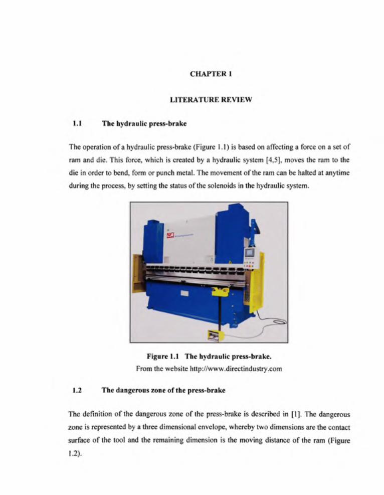
1.1 The hydraulic press-brak e
The operation of a hydraulic press-brake (Figure 1.1) is based on affecting a force on a set of
ram and die. This force, which is created by a hydraulic system [4,5], moves the ram to the
die in order to bend, form or punch metal. The movement of the ram can be halted at anytime
during the process, by setting the status of the solenoids in the hydraulic system.
Figure 1.1 Th e hydraulic press-brake .
From the website http://www.directindustry.com
1.2 The dangerous zone of the press-brak e
The definition of the dangerous zone of the press-brake is described in [1]. The dangerous
zone is represented by a three dimensional envelope, whereby two dimensions are the contact
surface of the tool and the remaining dimension is the moving distance of the ram (Figure
1.2).

Figure 1.2 Th e contact surface of the tool. From [1] (1997. pp. 37)
1.3 Th e existing protective systems
At present, there are many types of guards available for press-brakes:
Fixed guards : A fixed guard consists of an enclosure for the tools that prevents access of
fingers to the trapping area fi-om any direction (Figure 1.3).
Figure 1.3 Press-brak e fixed guard. From the website http://www.hsbeil.com

Interlocking guards: The interlocking guards consist of a screen across the full width of the
bed. This screen is mechanically linked and interlocked with the clutch circuit of the press-
brake and has to be down before the press will operate. Once the component material has
been loaded into the press brake and trapped by the descending ram, the guard screen rises
out of the way (Figure 1.4).
Figure 1.4 Press-brak e interlocking guard. From the website http://www.hsbeil.com
Distance ba r tri p guard : A distance bar trip guard incorporates a bar, with a screen to
prevent access to the tools from underneath. The bar is pulled out to a safe set distance by the
operator, and has to be at that distance before the clutch of the press-brakes will operate. This
bar is either locked in this position for the duration of the stroke or arranged so that any
movement of the bar towards the tools stops the ram of the press-brakes from descending.
The sides and the rear of the press-brakes fitted with this type of device are protected with
fixed guards (Figure 1.5).
Pullback device s an d photo-electri c safety devices: Pullback devices utilize a series of
cables attached to the operator's hands, wrists, and/or arms. This type of device is primarily
used on machines with stroking action. When the slide/ram is in the "up" position, the
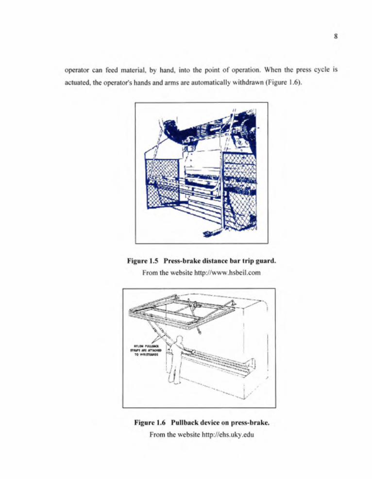
operator can feed material, by hand, into the point of operation. When the press cycle is
actuated, the operator's hands and arms are automatically withdrawn (Figure 1.6).
Figure 1.5 Press-brak e distance bar trip guard. From the website http://www.hsbeil.com
NTLON PULLBIC K j r iUPS AR E ATTUHE D
TO WRISTBAND S
" " • • - - . ^ '
Figure 1.6 Pullbac k device on press-brake. From the website http://ehs.uky.edu
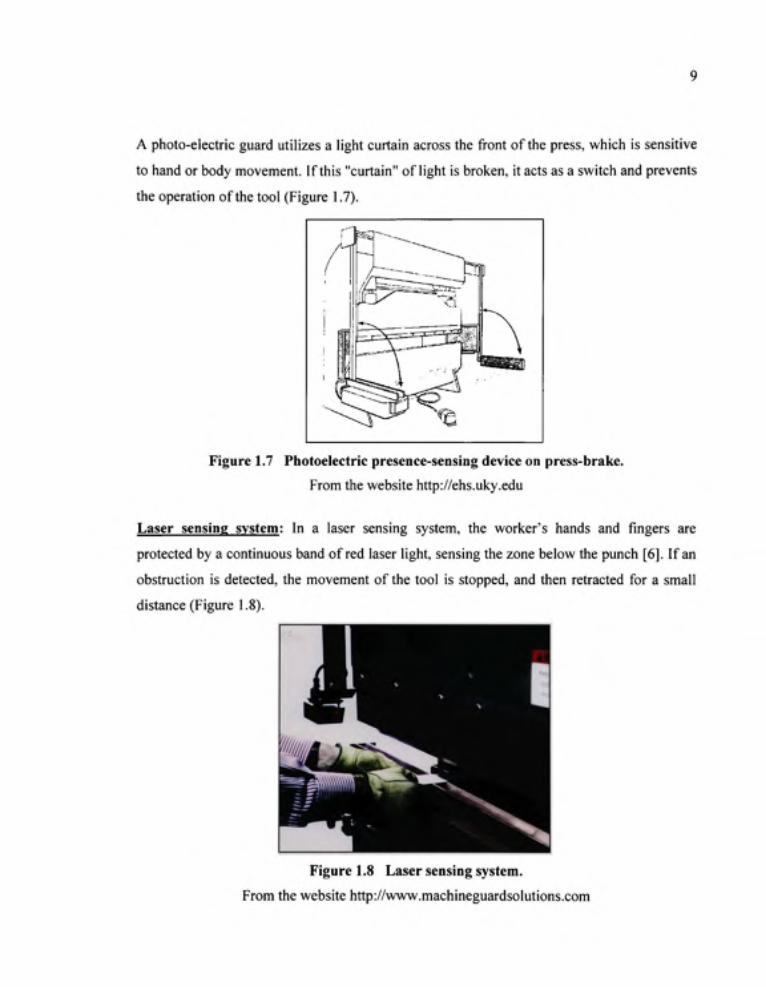
A photo-electric guard utilizes a light curtain across the front of the press, which is sensitive
to hand or body movement. If this "curtain" of light is broken, it acts as a switch and prevents
the operation of the tool (Figure 1.7).
Figure 1.7 Photoelectri c presence-sensing device on press-brake. From the website http://ehs.uky.edu
Laser sensin g system : In a laser sensing system, the worker's hands and fingers are
protected by a continuous band of red laser light, sensing the zone below the punch [6]. If an
obstruction is detected, the movement of the tool is stopped, and then retracted for a small
distance (Figure 1.8).
Figure 1.8 Lase r sensing system. From the website http://www.machineguardsolutions.com

Vision-based system : The vision-based system is equipped with a camera that mounts on the
punch protecting the worker's hands and fingers during the downward movement of the
punch (Figure 1.9). The system creates a safety zone below the punch that is monitored for
intrusion. The safety output makes a signal to stop the downward movement of the punch
whenever an intruding object is detected [7].
Figure 1. 9 Vision-base d safety equipment .
From the website http://www.thefabricator.com
1.4 The research of the protective system usin g vision
C. Kauffman et al. [8] presented a protective method using a vision system. This research
was aimed at detecting 2D location of a point of the worker's hand on the image. The
solution was based on using a color bracelet on a uniform background in order to extract the
bracelet image. By tracking the gravity center of the bracelet, it was possible to recognize the
tracking point location on the image. The safety distance was calibrated in the captured
image. The machine was stopped whenever the tracking point entered this distance.
J. Velten and A. Kummert [9] also developed a system based on a vision system, which
compared the camera image with an image of the empty workspace, having the dangerous

11
area. The inspection area covering the entire worker's hands was used to extract the
endangered components which were hands and fingers. The machine was stopped if the
dangerous area was intruded by the endangered components.
1.5 Th e related works of localization using vision
Ik-Hwan Kim et al. [10] described an active vision system used for object tracking and
distance measurement. The authors used a colored ball and the method of look up table, to
detect the object in the color image. After the extraction of the ball, the vision system moved
the cameras so that the ball's position was at the center of the image. The distance
information of the ball was calculated by the trigonometric measurement method.
Jong-Kyu Oh and Chan-Ho Lee [11] presented a stereo vision system for robot guidance.
The system included a PC based stereo vision system and a robot system. The interesting
point in this research is the investigation of the error when the work-piece is placed at
different depths. The experiment showed the change in error following a change of depth.
The error which occurred whenever the work-piece was located close to the sides of the
image was explained as the effect of lens distortion.
Takushi Sogo et al. [12] described a system for determining location using multiple cameras
placed in space, focused in different directions. The results of the paper concentrated mainly
on precision. The investigation showed the value of the error whenever the object was placed
on some position in 2D space. Moreover, the authors noted that the degree of precision was
dependent on various factors such as: the number of sensors, the arrangement of the sensors,
and so on.
1.6 Conclusio n
Table 1.2 shows the evolution of the protection methods over time. At the beginning, the
principle is to prevent the worker's hands entering the dangerous zone. In the next
generation, the principle is to detect the obstruction of the worker's hands using the sensor.

12
which is fixed at a specific distance (the safety distance) from the punch. However, the
protective systems presented previously are not able to protect the operator's hands in cases
involving the making of small pieces or trays (Figure 1.10).
fa) (b)
Figure 1.1 0 Ris k of hand injury in cases involving working with small pieces or trays using press-brakes .
(a) making small pieces and (b) making trays. From [7] (2007, pp. 12)
Table 1.2 The evolution of the protection methods.
Principles
Preventing the worker's hands from entering
the dangerous zone.
Stopping the machine whenever an obstruction
is detected, fixed protective volume.
Tracking the worker's hands using vision (2D),
fixed protective volume.
Tracking the worker's hands using vision (3D),
flexible protective volume.
Systems/Researches
Fixed guards, interlocking guards, distance bar trip
guard, pullback devices, and two buttons.
Light curtain, laser sensing system, and vision
based system.
C. Kauffman etal.( 1996).
J. Veltel and A. Kummert (2003).
Research work presented in this thesis.

13
Moreover, the existing systems, including the ones using vision technique, do not consider
the direction of the movement of the worker's hands; therefore they are not able to
distinguish the dangerous movements from the safe ones. By consequence, they tend to stop
the press-brake unnecessarily, and in absence of danger.
The new protective system presented in this thesis has two goals: firstly, tracking the
worker's hands using 3D vision; and secondly, generating the flexible protective volume.

CHAPTER 2
THE FLEXIBLE PROTECTIVE SYSTE M WITH SINGLE-POINT INSPECTIO N
2.1 Principl e and definition s
2.1.1 Principl e
The operation of the proposed system is based on the flexible interdiction zone. The space in
front of the punch is divided into three zones. The first one, which is close to the tool, is
called the initial interdiction zone. It is formed without considering the motion of the
worker's hand. The next zone is the fiexible interdiction zone, in which any intrusion must
stop the press-brake. The third zone is the inspection zone, where the kinematic parameters
of the worker's hand are determined using two cameras. These parameters are the position
and the instantaneous velocity of a given point on the worker's hand. The shape and
dimensions of the flexible interdiction zone will be determined using the second parameter in
conjunction with the machine stopping time and the calculation time of the processing loop.
The stop control system is activated whenever the given point on the worker's hand interferes
with the flexible interdiction zone (Figure 2.1).
2.1.2 Definition s
The zones mentioned previously in the principle are defined as follows:
The inspecte d poin t is the center of an emitting bracelet worn by the worker during the
operation.
The initial interdiction zone , denoted as Pi, is represented by a three-dimensional envelope.
Its dimensions depend firstly on the operating space of the punch, secondly on the distance
between the inspected point and the tip of the middle finger of the worker's hand, and finally,
on the maximum error of the location method (Figure 2.2). This zone is always fixed and
independent of the motion of the worker's hand.

15
Emitting bracelet
1 Initial interdiction zone 2 Flexible interdiction zone 3 Inspection zone
ki£^
u LDG
(b)
(a)
ft3=:> u kig^
Stop U k_gv]
(C) (d)
Figure 2.1 Th e operational principle of the proposed system. (a) three zones of the fiexible protective system. (b) the condition for the establishment of the flexible interdiction zone. (c) the instantaneous flexible interdiction zone is generated if the instantaneous velocity
intersects with the initial interdiction zone. (d) the activation of the stop signal depends on the interference between the given point
on the worker's hand and the flexible interdiction zone.
Figure 2.2 Dimension s of the initial interdiction zone.
16
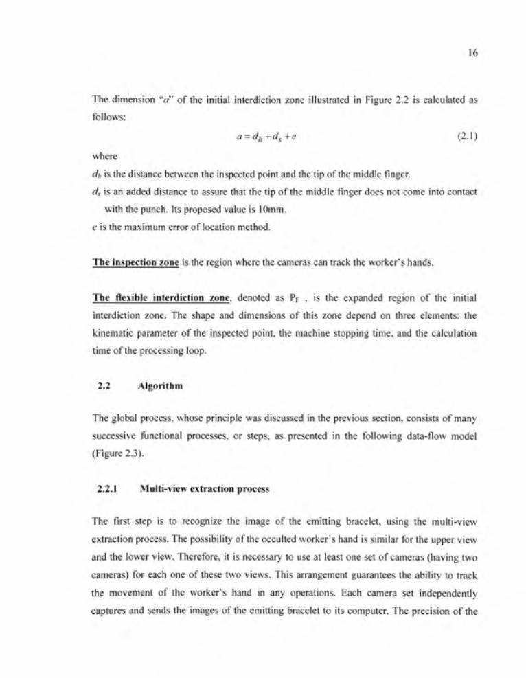
The dimension "a" of the initial interdiction zone illustrated in Figure 2.2 is calculated as
follows:
a = dfj+dg+e (2.1)
where
dh is the distance between the inspected point and the tip of the middle finger.
ds is an added distance to assure that the tip of the middle finger does not come into contact
with the punch. Its proposed value is 10mm.
e is the maximum error of location method.
The inspection zone is the region where the cameras can track the worker's hands.
The flexible interdictio n zone , denoted as PF , is the expanded region of the initial
interdiction zone. The shape and dimensions of this zone depend on three elements: the
kinematic parameter of the inspected point, the machine stopping time, and the calculation
time of the processing loop.
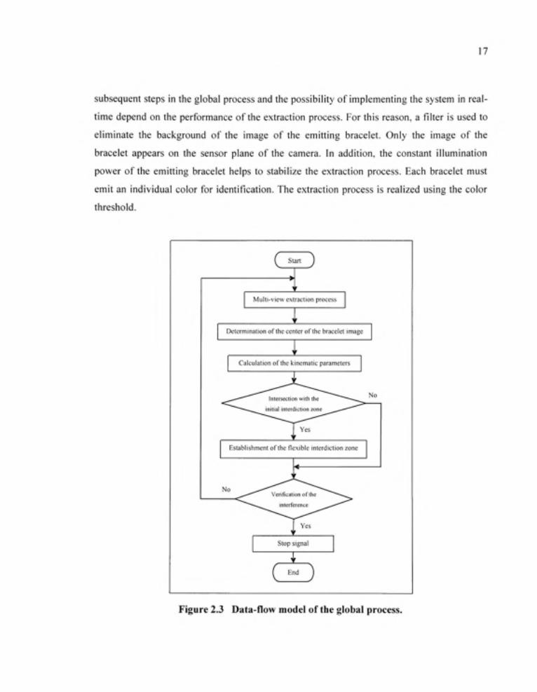
2.2 Algorith m
The global process, whose principle was discussed in the previous section, consists of many
successive functional processes, or steps, as presented in the following data-fiow model
(Figure 2.3).
2.2.1 Multi-vie w extraction process
The first step is to recognize the image of the emitting bracelet, using the multi-view
extraction process. The possibility of the occulted worker's hand is similar for the upper view
and the lower view. Therefore, it is necessary to use at least one set of cameras (having two
cameras) for each one of these two views. This arrangement guarantees the ability to track
the movement of the worker's hand in any operations. Each camera set independently
captures and sends the images of the emitting bracelet to its computer. The precision of the
17
subsequent steps in the global process and the possibility of implementing the system in real
time depend on the performance of the extraction process. For this reason, a filter is used to
eliminate the background of the image of the emitting bracelet. Only the image of the
bracelet appears on the sensor plane of the camera. In addition, the constant illumination
power of the emitting bracelet helps to stabilize the extraction process. Each bracelet must
emit an individual color for identification. The extraction process is realized using the color
threshold.
( start J
Multi-view extraction process
Determination of the center of the bracelet image
Calculation of the kinematic parameters
Establishment of the flexible interdiction zone
No
Figure 2.3 Data-flo w model of the global process.

18
Let three matrices Ij ;7=1,..,3 be the red, green, and blue elements of the captured image. The
threshold Tjk needed for extraction of the ^* bracelet image of each matrix is chosen by visual
observation of the histogram plot and of the specific color of the bracelet. A=1,..,Z); b is the
number of the bracelet. The resulting binary image of each bracelet, denoted as Hk , is
determined as follows:
//^=GiG2G3 (2.2)
where
[0 otherwise (2.3)
u is rows of the matrix.
V is columns of the matrix.
2.2.2 Determinatio n of the center of the bracelet image
On the sensor plane of the camera, the circular bracelet appears as a pixel cloud whose form
could be approximated as a line or as an ellipse, depending on the relative positions of the
bracelet and the camera. Keeping in mind that the inspected point is the virtual center of the
bracelet on the worker's hand, its projection is assumed to be the midpoint of the line or the
center of the ellipse.
Firstly, it is necessary to verify the linearity of the pixels having value "one" in the binary
image, using a correlation coefficient r. n
^ UjVj — n.u.v 7 = 1
i .'=1 -n{uf -n{v)^
r =
where
r is the correlated coefficient.
Uj, V, are coordinates of the /* pixel having value "one" pixel in the binary image.
n is the total of pixels having value "one" in the binary image.
19
u is mean of M,
V is mean of v,
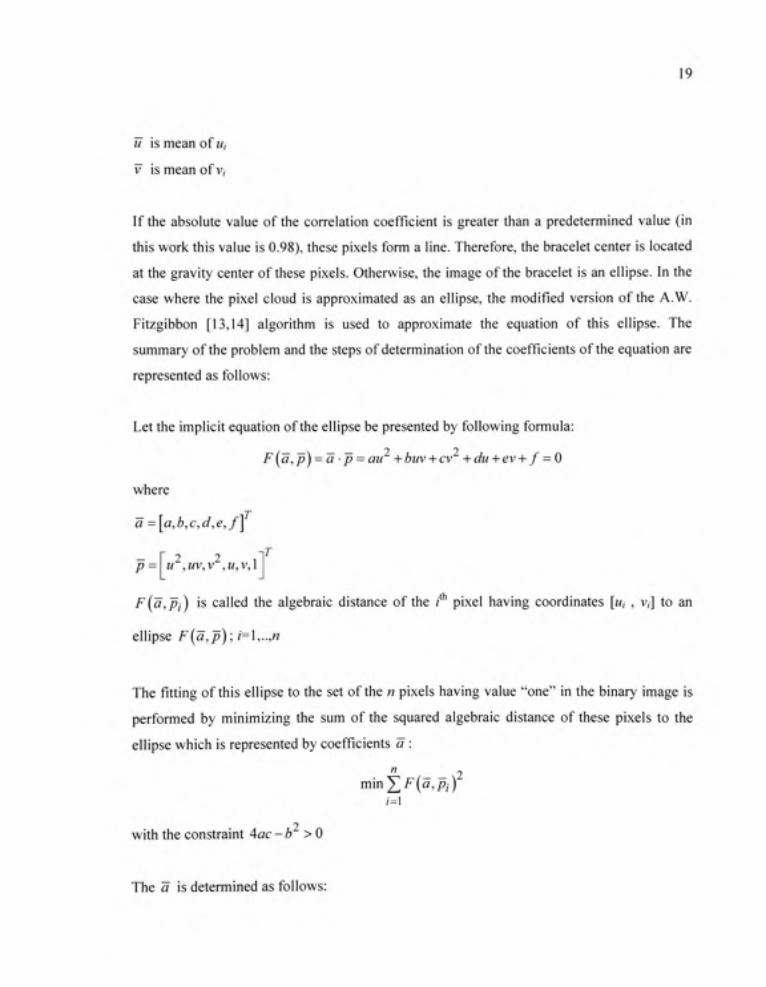
If the absolute value of the correlation coefficient is greater than a predetermined value (in
this work this value is 0.98), these pixels form a line. Therefore, the bracelet center is located
at the gravity center of these pixels. Otherwise, the image of the bracelet is an ellipse. In the
case where the pixel cloud is approximated as an ellipse, the modified version of the A.W.
Fitzgibbon [13,14] algorithm is used to approximate the equafion of this ellipse. The
summary of the problem and the steps of determination of the coefficients of the equation are
represented as follows:
Let the implicit equation of the ellipse be presented by following formula:
F{a,p) = a •p = au +buv + cv +du + ev + f = 0
where
a = [a,b,c,d,e,f]
r nT 2 2
P= U ,UV,V , M, V, 1
F(a,pj) is called the algebraic distance of the / pixel having coordinates [M, , v,] to an
ellipse F[a,p); i=\,..,n
The fitting of this ellipse to the set of the n pixels having value "one" in the binary image is
performed by minimizing the sum of the squared algebraic distance of these pixels to the
ellipse which is represented by coefficients a :
m'mY,F{a,Pi)
2 with the constraint 4ac -b > 0
The a is determined as follows:

20
a = «1
-S^^S^ai^ (2.4)
where
«! is the minimal eigenvector of M = Ci \5'i-5'25'3'5'J j which satisfies the condition
4ac-b^>0
C,= 0 0 2
0 2'
-1 0 0 0
Do
"1 1 1
Uj Vj 1
u„ v„ 1
Si^DiD,
S2 = D[D2
S^=DID2
A
"'
"'
2
"1 1
M,V,-
"«'l'«
vr
V?
^i
Finally, the coordinates of the ellipse center are calculated using the coefficients of the
approximated equation [15]. The coordinates of the ellipse center [Mec,Vgc] are calculated
using the following formula:
_be- 2cd SC 9 ~
4ac-b (2.5) _ bd-2ae
''~ 4ac-b^
2.2.3 Calculatio n of the kinematic parameters
The kinematic parameters, which are the position and the instantaneous velocity of the
inspected point, are calculated independently for each view.

21
2.2.3.1 Determinatio n o f the location of the bracelet center
In order to calculate the 3D coordinates of the bracelet center, it is necessary first to
determine the camera matrix, then to establish the correspondence of the bracelet image
center in the two images appearing in the two cameras.
Determination o f the camera matrix : The camera matrix relates the 2D position of a point
in the image to its 3D location in space. The direct linear transformation method [16] is used
to determine the camera matrices. The summary of the method is as follows:
The camera view and focus are fixed. A calibration object with known coordinates is placed
in the scene. The calibration object has n points. The 3D coordinates of the j point is
(xj,yj,zj\;j=l..n. The 2D coordinates of the projection of they* point on the left and the
right camera are {^i'j,^vj\ and i^Uj,^vj] . Let ^C and ^C be the left and the rig; ht
camera matrix.
Firstly, calculation of the A and B matrix
xi yi zi I 0 0 0 0 -x j Ml -yi u\
A =
0 0 0 0 xi >'!
^« >'« -« 1 0 0 0 0 -^n "« -yn "n
0 0 0 0 x„ y„ z„ \ -x„^v„ -y„^v„
'Ml
, Z, L L 1 -xi vi ->'] vi - r i vi
X; yj Zj \ 0 0 0 0 -Xj Uj -yj u.- -Zj u.-
0 0 0 0 x . yj Zj 1 -xj'vj -y/vj -Zj^Vj
L,
B =
The left camera matrix is determined by this formula:

22
^C = (^^^) A^B (2.6)
Performed similarly for the right camera, this will give the necessary two camera matrices.
Determination o f the correspondence o f the bracele t imag e center: In order to determine
the 3D position of the bracelet center by a vision method, at least two cameras must be used
[17]. The key problem then becomes how to establish the correspondence of the bracelet
image center appearing in two cameras. The feature-based matching method was adopted for
this work. The corresponding feature in this case is the bracelet image center. Keep in mind
that in the case of muhiple bracelets, the image of each bracelet in two cameras was already
identified in the extraction process.
Computation o f th e 3 D coordinate s o f th e bracele t center : It is known that the bracelet
center lies on the ray determined by the coordinates of the bracelet image center and the
camera matrix. As a result, it must be at the intersection of the lines generated by two
cameras. Due to the precision of the approximation and the determination of the camera
matrix, the rays might not always intersect. In that case, the midpoint of the connecting
segment between the two rays is considered as the inspected point [18].
The requirements for calculation of the 3D coordinates of the bracelet center x , are as
follows: Firstly, the cameras matrices C and C. Secondly, the coordinates of the bracelet
image center ( M^^ , " V^ J and | ^M^^ , ^v^ j .
The two equations to determine the ray passing through the left bracelet image center use the
camera matrix C and the coordinates of the bracelet image center! Ug^, ^ecl-
L IL L L \ , IL L L \ , ( L L L \ L ^ec=\ ^ 1 1 - C31 u^c^ + y C12- C32 Ugc)y + \ cu- C33 WecJ2+ Ci4
L IL L L \ , IL L L \ , IL L L \ , L Vec=( ^ 2 1 - ^31 ^ecjx + [ ^ 2 2 - C32 v^^jy + l C23 - C33 Vg^Jz+ C24
23
The remaining ray is determined by using the camera matrix C and the coordinates of the
bracelet image center! ^Ug^.. ^v^^ \.
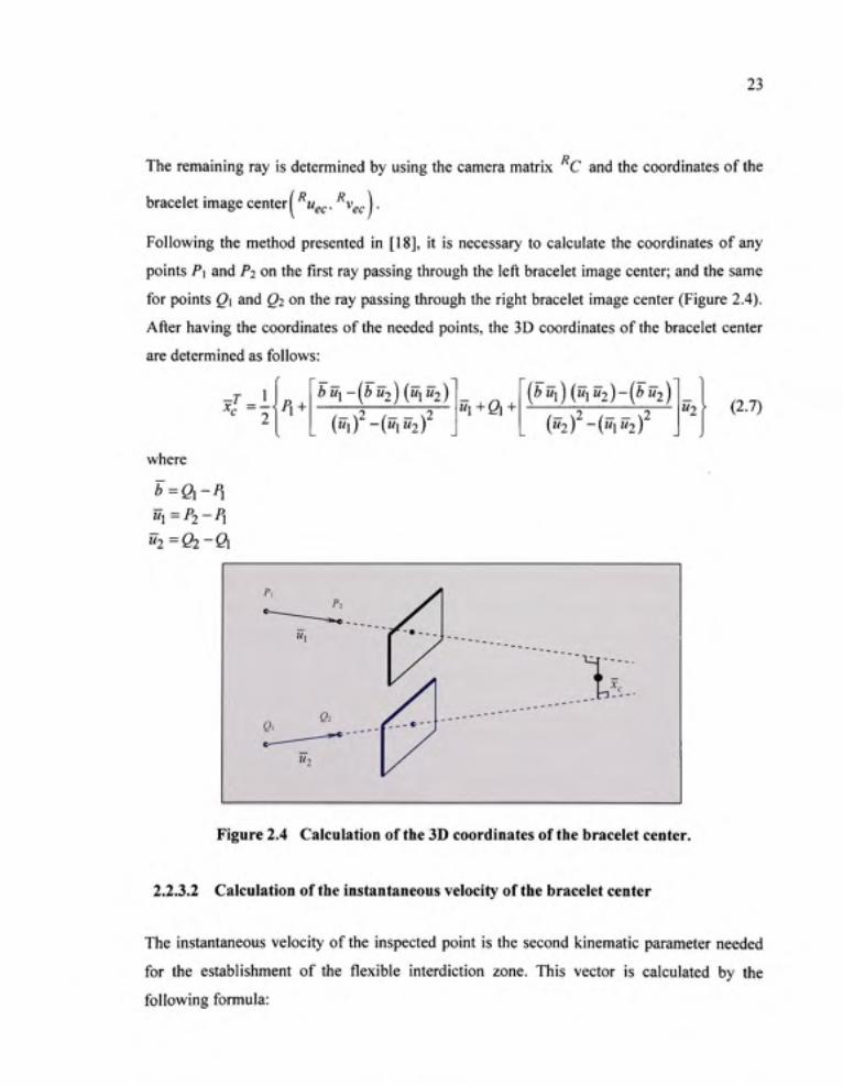
Following the method presented in [18], it is necessary to calculate the coordinates of any
points P\ and P2 on the first ray passing through the left bracelet image center; and the same
for points Q\ and Q2 on the ray passing through the right bracelet image center (Figure 2.4).
After having the coordinates of the needed points, the 3D coordinates of the bracelet center
are determined as follows:
^T P^ + bu^-[bu2){uxU2)
("1) -("i"2) "1+01 +
( Z > M I ) ( M I M 2 ) - ( ^ " 2 )
("2) - (" i"2 ) "2 (2.7)
where
b=Qi-Pi ui=P2-Pi "2 =02-ft
Figure 2.4 Calculatio n of the 3D coordinates of the bracelet center .
2.2.3.2 Calculatio n o f the instantaneous velocity of the bracelet center
The instantaneous velocity of the inspected point is the second kinematic parameter needed
for the establishment of the flexible interdiction zone. This vector is calculated by the
following formula:

24
rr _ Xf X^-l^t (2.8) A/
where
X; is the actual position of the inspected point.
x,_^, is the previous position of the inspected point.
A? is the time interval between two captured images.
2.2.4 Establishmen t o f the flexible interdiction zon e
The flexible interdiction zone constitutes the principal element of the proposed solution for
improving the flexibility of the system.
2.2.4.1 Dimension s of the flexible interdiction zone
The dimensions of the flexible interdiction zone are determined considering the
instantaneous velocity of the inspected point and the calculation time of the processing loop,
as well as the machine stopping time. If the instantaneous velocity intersects the initial
interdiction zone, the instantaneous flexible interdiction zone is generated (Figure 2.5).
Initial interdiction zone _ _ Flexible interdiction zone
Inspected point
Figure 2.5 Determinatio n o f the flexible interdiction zone.
The vector for the dimensional change is calculated as follows:
c=-A:(27]n, +7;c)v;- (2.9)

25
where
_ Jv, if V; intersects with Pj
[ 0 ortherwise
X; is the actual position of the inspected point.
v is the instantaneous velocity of the inspected point.
Vj is the instantaneous velocity of the inspected point whenever the condition of the
intersection between this vector and the boundary of the initial interdiction zone is
satisfied.
k is the safety coefficient.
Tsc is the machine stopping time.
Tim is the maximum time of the processing loop.
2.2.4.2 Shap e of the flexible interdiction zone
The shape of the flexible interdiction zone is determined by considering the interrelation
between the direction of instantaneous velocity of the inspected point and the initial
interdiction zone. Therefore thirteen possible shapes of the flexible interdiction zone can be
generated (Appendix I). In a multi-view system, the flexible interdiction zones are
established independently for each view.
2.2.4.3 Exampl e
In this section, a numerical example of establishing the flexible interdiction zone is
presented. The data are as follows :
- the punch stroke of the press-brake: 154mm;
- the punch length of the press-brake: 305mm;
- the machine stopping time as presented in an example of ANSI [19] for calculating the
safety distance T^^ = 0.18s ;
- the maximum time of the processing loop of this system T^^ = 0.4s;
26
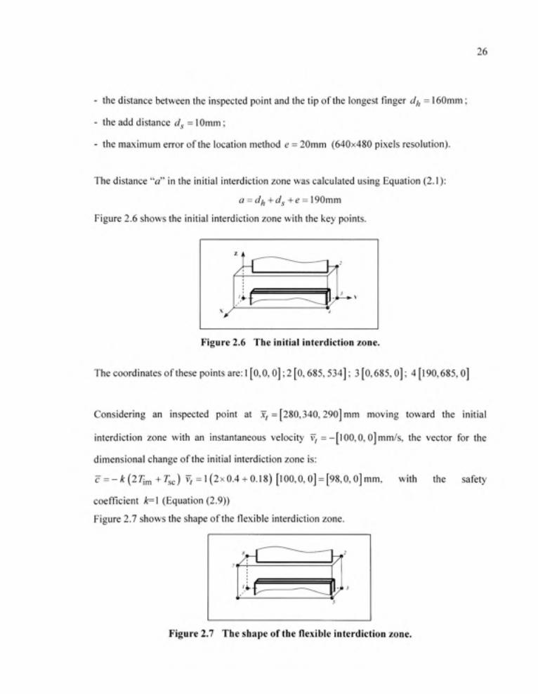
- the distance between the inspected point and the tip of the longest finger dj^ = 160mm;
- the add distance dg = 10mm;
- the maximum error of the location method e = 20mm (640x480 pixels resolution).
The distance "a" in the initial interdiction zone was calculated using Equation (2.1):
a = di^+dg+e = \ 90mm
Figure 2.6 shows the initial interdiction zone with the key points.
Figure 2.6 Th e initial interdiction zone.
The coordinates of these points are: 1 [0,0, O]; 2 [0,685,534]; 3 [0,685, O]; 4 [190,685,0]
Considering an inspected point at x, =[280,340,290] mm moving toward the initial
interdiction zone with an instantaneous velocity v, =-[lOO,0, 0]mm/s, the vector for the
dimensional change of the initial interdiction zone is:
c=-A:(27im+7;c) ? =1(2x0.4 + 0.18) [100,0,0] = [98,0,0]mm, with the safety
coefficient k=\ (Equation (2.9))
Figure 2.7 shows the shape of the flexible interdiction zone.
Figure 2.7 Th e shape of the flexible interdiction zone .

27
Coordinates of the key points of the flexible interdiction zone are: 1 [0,0, O]; 2 [O, 685, 534];
3 [0,685,0]; 5 [288,685,0]; 7 [288,0,534]
2.2.5 Verificatio n o f the interferenc e betwee n th e inspecte d poin t an d th e flexible interdiction zone
For each view, every moving inspected point establishes a corresponding flexible interdiction
zone. The activation of the stop signal depends on the interference between these two
elements. This interference is verified using the spatial traversability vector. The first stop
signal generated by one of the two views will stop the machine.
2.2.5.1 Th e spatial traversability vector
The original planar traversability vector was proposed in the literature as a mean to verify the
relative position between a point and a convex polygon [20]. In order to verify the relative
position between the inspected point and the flexible interdiction zone, which is a convex
polyhedron, it is necessary to develop a new mathematical set of equations called spatial
traversabilty vector applicable for a 3D case.
Definition o f th e spatia l traversabilit y vector : The spatial traversability vector of a point
X with respect to the r-sides convex polyhedron is defined as an r-tuple vector:
7(x,PF)=[sgn(/ i) ,sgn(/2) , . . . ,sgn(/ , )] (2.10)
where f^ represents the algebraic distance between the point x and the plane k as follows:
fk x-x-ik y-y\k --=\k
X2k-x\k yik-yu ^ik-^k ^Sk-^lk y3k-y\k ^3k-^\k
(2.11)
where xjk , yjk , Zjk are the coordinates of they* point (/•=1,..,3) creating the k^ plane {k=\,..,r)
and X, y, z are the coordinates of the point x .

28
Determination o f the direction o f the normal vector o f the k^ plane: The direction of the
normal vector of a plane is determined using the right-hand rule. For example, the positive
direction of the normal vector n of the plane created by three key points 1, 2, and 3 as shown
in Figure 2.8 is, from left to right, derived from the cross product " = (^3 -^2)^(^1 "^2 ) •
Figure 2.8 The norma l vector.
Determination o f the algebraic distanc e f^ between th e poin t x an d th e k^ plane: The
algebraic value of the distance between the point x and the A:* plane was determined by the
direction of the normal vector of this plane and the position of the point x relative to this
plane. The algebraic value of this distance is obtained by replacing the coordinates of the
point X in Equation (2.11). The sgn operator assigns a value of-1, 0, or +1 to the algebraic
distance /^ depending on its sign.
Determination o f th e spatia l traversabilit y vector : The spatial traversability vector
representing the relative position between a point x and a convex polyhedron of r-sides
contains r components of sign /^ with k varies from 1 to r. Note that a point x located inside
the polyhedron generates a known and unique spatial traversability vector.
2.2.5.2 Exampl e
In this example, the r-sides convex polyhedron is the flexible interdiction zone in the
example presented in Section 2.2.4.3. The flexible interdiction zone is limited by 6 planes
{r=6) (Figure 2.9), from 1 to 6 which were formed by the key points following a

29
predetermined order: plane 1 (points 8, 1, 6); plane 2 (points 1, 3, 5); plane 3 (points 2, 3, 5);
plane 4 (points 7, 8, 2); plane 5 (points 8, 1, 3); plane 6 (points 7, 6, 5). The coordinates of
these key points were given previously.
7^
6
^ ^ -^-.
- l i />i> ^ ^ t ^ 5
I-'
Figure 2.9 Th e flexible interdiction zone and the normal vector of the plane 1.
Using Equation (2.11), the algebraic distances between an inspected point
X; =[280,340, 290] mm which was located inside of the flexible interdiction zone and the
plane 1 of this polyhedron was:
x -x j i y-y\\ --:^\\ 280-0 340-0 290-534
/ l = X2i-xii >'2i->'ii ^21-^11= 0 - 0 0 - 0 0-534 =-52289280
^31-^11 >'31->'ll ^31-^11 288-0 0 - 0 0-534
Similarly,
/2 =-57211200 / 3 = 53058240 /4 =48136320 / 5 = 102421200 /6=-2926320
The spatial traversability vector of the inspected point determined by Equation (2.10) was:
7 ( X „ P F ) =[-1,-1,1,1,1,-1]
Similarly, any point located inside the flexible interdiction zone had the same spafial
traversability vector.

30
2.3 Experimenta l
2.3.1 Tes t bench
A test bench was built (Figure 2.10) to simulate the operation of the present algorithm. This
test bench includes a press-brake simulator, two mechanical hands, and a flexible protection
system based on vision. An aluminium frame whose upper horizontal bar can move up and
down was used to simulate the press-brake. The movement of the upper bar was realized by
an electric motor and a ball screw. The motor was controlled by a pedal. The punch was
attached on the upper bar whereas the die was attached on the lower bar. Two mechanical
hands were mounted on two tracks in front of the press-brake. The vision system consists of
two digital stereo heads, filters, and emitting bracelets which were fixed on the mechanical
hands. The stereo heads were made by Videre Design®. Each of them contained two 6mm
focal length lenses. One stereo head was mounted on the upper part of the press-brake
whereas the second one was mounted on the lower part of the press-brake. Each stereo head
was connected to a computer (Intel® Core 2 Duo 2.66GHz). The welder shade#5 glasses were
used as filters. The calculation was executed using a program written in MATLAB .
Figure 2.10 Th e test bench equipped with a flexible protective system using multi-view vision.
31
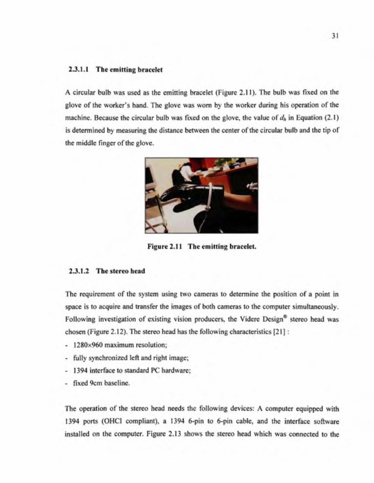
2.3.1.1 Th e emitting bracelet
A circular bulb was used as the emitting bracelet (Figure 2.11). The bulb was fixed on the
glove of the worker's hand. The glove was worn by the worker during his operation of the
machine. Because the circular bulb was fixed on the glove, the value of df, in Equation (2.1)
is determined by measuring the distance between the center of the circular bulb and the tip of
the middle finger of the glove.
Figure 2.11 Th e emitting bracelet.
2.3.1.2 Th e stereo head
The requirement of the system using two cameras to determine the position of a point in
space is to acquire and transfer the images of both cameras to the computer simultaneously.
Following investigation of existing vision producers, the Videre Design® stereo head was
chosen (Figure 2.12). The stereo head has the following characteristics [21] :
- 1280x960 maximum resolution;
- fiilly synchronized left and right image;
- 1394 interface to standard PC hardware;
- fixed 9cm baseline.
The operation of the stereo head needs the following devices: A computer equipped with
1394 ports (OHCI compliant), a 1394 6-pin to 6-pin cable, and the interface software
installed on the computer. Figure 2.13 shows the stereo head which was connected to the

32
computer. After installing the interface software Small Vision System (SVS), it is possible,
using the instruction of "cmat", to set the parameters of the stereo head and to transfer the
images to the MATLAB' workspace.
Figure 2.12 Th e stereo head.
Figure 2.13 Connectio n of a stereo head with a computer.
2.3.1.3 Imag e acquisition
A support library was used to interface with MATLAB . This allows the user to program the
whole process in MATLAB®. A testing function was written to determine the time needed to
transfer the images from the stereo head to MATLAB® under the various image sizes. Table
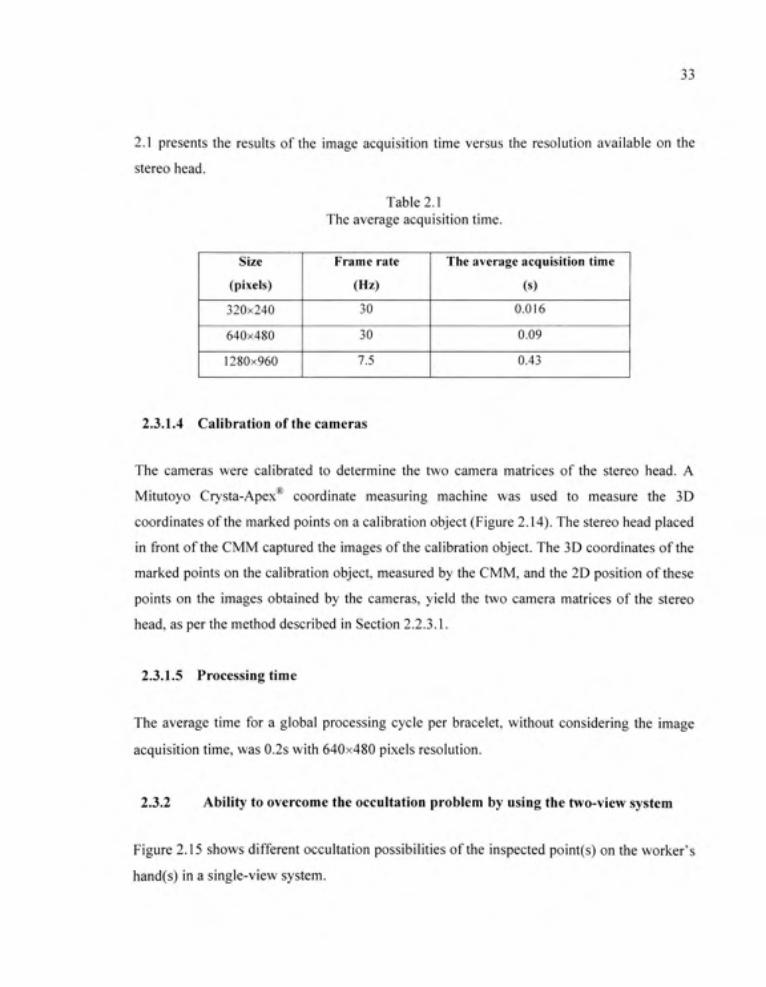
33
2.1 presents the results of the image acquisition time versus the resolution available on the
stereo head.
Table 2.1 The average acquisition time.
Size
(pixels)
320x240
640x480
1280x960
Frame rate
(Hz)
30
30
7.5
The average acquisition time
(s)
0.016
0.09
0.43
2.3.1.4 Calibratio n of the cameras
The cameras were calibrated to determine the two camera matrices of the stereo head. A
Mitutoyo Crysta-Apex coordinate measuring machine was used to measure the 3D
coordinates of the marked points on a calibration object (Figure 2.14). The stereo head placed
in front of the CMM captured the images of the calibration object. The 3D coordinates of the
marked points on the calibration object, measured by the CMM, and the 2D position of these
points on the images obtained by the cameras, yield the two camera matrices of the stereo
head, as per the method described in Section 2.2.3.1.
2.3.1.5 Processin g time
The average time for a global processing cycle per bracelet, without considering the image
acquisition time, was 0.2s with 640x480 pixels resolution.
2.3.2 Abilit y to overcome the occultation proble m b y using the two-view system
Figure 2.15 shows different occultation possibilities of the inspected point(s) on the worker's
hand(s) in a single-view system.
34
^B '
^ |B Figure 2.14 Determinatio n of the coordinates of the marked points
on the calibration object.
Figure 2.15 Possibilitie s of occultation of the inspected points. (a) both of the inspected points are absent in the top view. (b) both of the inspected points are absent in the bottom view. (C) one of the inspected points is absent in each view. (d) the inspected points are wrongly determined by the image of a partly hidden bottom
view.
The two-view system which has two sets of cameras placed one at the upper and one at the
lower part of the press-brake permits the elimination of the occultation problem. In fact,
35
when the inspected points enter the inspection zone, they can be tracked by at least one
camera set. In the case shown in Figure 2.15a the worker's hands are tracked by the lower
set. Figure 2.15b shows the situation where the hands are tracked by the upper set; whereas in
the case of Figure 2.15c each camera set tracks one hand. In the case where the bracelets are
partly hidden in the bottom view, as shown in Figure 2.15d, the bracelets still appears fully in
the upper view. Therefore, the position of the inspected point is determined correctly by the
upper view.
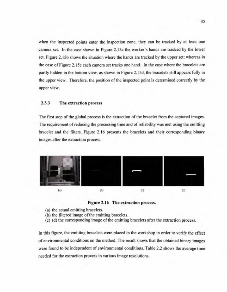
2.3.3 Th e extraction proces s
The first step of the global process is the extraction of the bracelet from the captured images.
The requirement of reducing the processing time and of reliability was met using the emitting
bracelet and the filters. Figure 2.16 presents the bracelets and their corresponding binary
images after the extraction process.
(a) (b) (c) (d)
Figure 2.16 Th e extraction process .
(a) the actual emitting bracelets. (b) the filtered image of the emitting bracelets. (c) (d) the corresponding image of the emitting bracelets after the extraction process.
In this figure, the emitting bracelets were placed in the workshop in order to verify the effect
of environmental conditions on the method. The result shows that the obtained binary images
were found to be independent of environmental conditions. Table 2.2 shows the average time
needed for the extraction process in various image resolutions.
36
Table 2.2 The average time needed for the extraction process in various image resolutions.
Resolution
(pixels)
320 X 240
640 X 480
1280x960
The average time of the extraction process
(s)
0.05
0.1
0.4
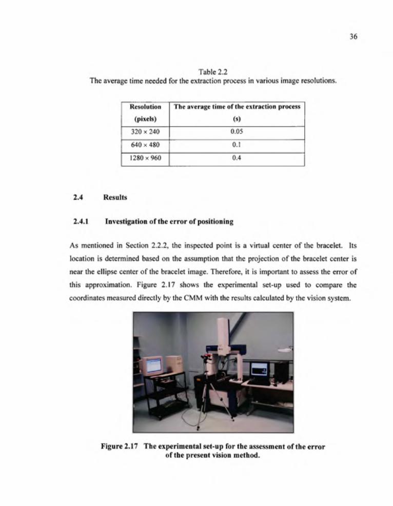
2.4 Results
2.4.1 Investigatio n of the error of positioning
As mentioned in Section 2.2.2, the inspected point is a virtual center of the bracelet. Its
location is determined based on the assumption that the projection of the bracelet center is
near the ellipse center of the bracelet image. Therefore, it is important to assess the error of
this approximation. Figure 2.17 shows the experimental set-up used to compare the
coordinates measured directly by the CMM with the results calculated by the vision system.
Figure 2.17 Th e experimental set-up for the assessment of the error of the present vision method .
37
A mechanical hand wearing the emitting bracelet was placed on the table of the CMM. The
stereo head was placed in front of the CMM. The optical axis of the camera is neither
perpendicular, nor parallel to the movement direction of the bracelet. The computer on the
left hand side of the CMM, which was connected to the stereo head, calculated the position
of the bracelet center by the presented method. The computer on the right side of the CMM
displayed the coordinates of the center of the bracelet measured by the CMM. In order to
compare the results of the two methods, the machine reference of the CMM was used in all
the measurements. The error was evaluated by the difference between the measured position
and the calculated position of the bracelet center.
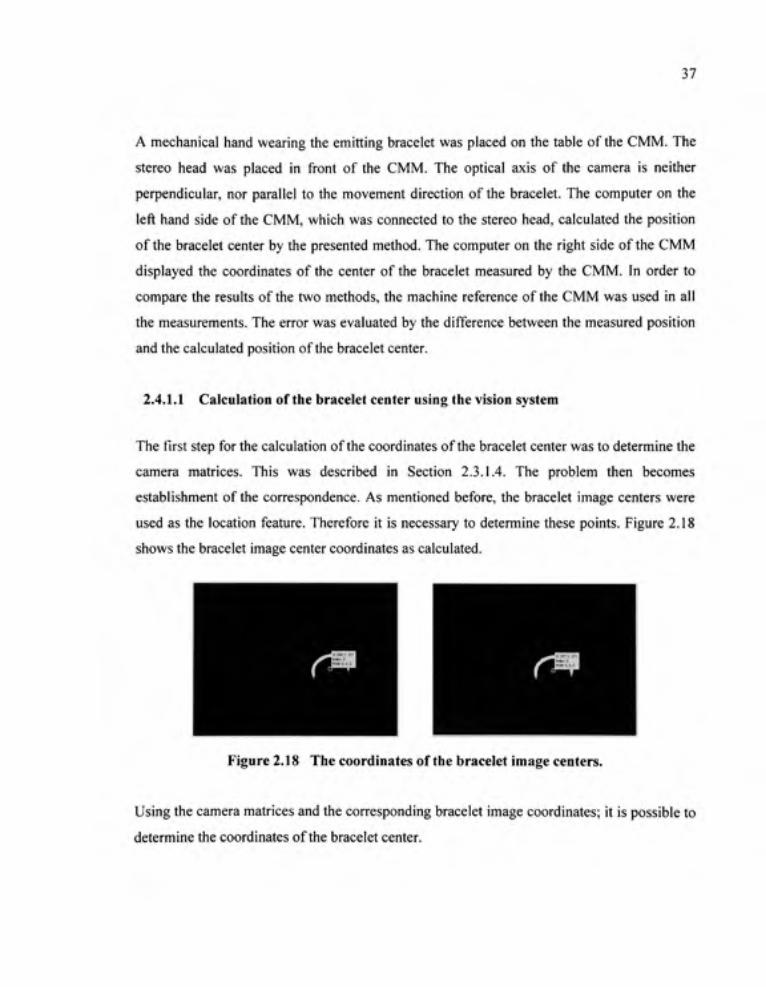
2.4.1.1 Calculatio n of the bracelet center using the vision system
The first step for the calculation of the coordinates of the bracelet center was to determine the
camera matrices. This was described in Section 2.3.1.4. The problem then becomes
establishment of the correspondence. As mentioned before, the bracelet image centers were
used as the location feature. Therefore it is necessary to determine these points. Figure 2.18
shows the bracelet image center coordinates as calculated.
Figure 2.18 Th e coordinates of the bracelet image centers.
Using the camera matrices and the corresponding bracelet image coordinates; it is possible to
determine the coordinates of the bracelet center.

38
2.4.1.2 Measuremen t o f the bracelet center using coordinate measurin g machin e
The coordinates of the bracelet center were also determined independently using CMM
(Figure 2.19). Because the bracelet is circular in shape, the CMM function for circle
measurement was used. The result of the measurement supplies the necessary information,
including the coordinates of the center of the circle and the diameter of the circle.
2.4.1.3 Th e differenc e betwee n th e measure d positio n an d th e calculate d positio n o f the bracelet center
Due to the experimental conditions, it was decided to focus on two factors: firstly the
distance between the stereo head and the bracelet, and secondly the image resolution. Table
2.3 illustrates the difference between the coordinates measured by the CMM and the results
obtained by the vision system in various distances under two resolutions: 640x480 pixels and
1280x960 pixels.
Figure 2.19 Measuremen t of the bracelet center using CMM.

39
Table 2.3 The difference between the coordinates measured by the coordinate measuring machine and
the resuhs obtained by the vision method in various distances and resolutions.
Distance
-700 mm
--800 mm
-900 mm
-1000 mm
Measured by the CMM
(1)
[422±0.5,41±0.5, 166±0.5]
[422±0,5, I82±05, 166±0.5]
[422±0.5,282±0.5, 166±0.5]
[422±0.5, 377±0,5, 166±0.5]
Resolution 1280x960
lx,y,zV
(2)
[424±0,3, 48±0.5, 164±0.3]
[423±0.3, 190±0.5, 164±0.3]
[424±0.3, 292±0.5, 163±0.3]
[424±0.3, 389±0.5, 163±0.3]
Resolution 640x480
\x,y. zj*
(3)
[427±0.3, 56±0.5, 157±0.3]
[427±0.3, 198±0.5, 157±0.3]
[428±0.3, 300±0,5, 156±0,3]
[428±0.3, 396±0.5, 156±0.3]
Difference**
[Ax, Ay, AzV
(4) = ( l )-(2)
[-2, -7, 2]
[-1,-8,2]
[-2,-10,3]
[-2,-12,3]
Difference**
\Ax, \y, Azj*
(5) = ( l)-(3)
[-5,-15,9]
[-5,-16,9]
[-6,-18,10]
[-6,-19,10]
mmm * difference between the mean values
Columns (4) and (5) of Table 2.3 show that firstly, the higher the image resolution, the better
the precision and secondly, the farther the distance separating the stereo head and the bracelet
in the y direction, the larger the difference between the values of the y coordinate obtained by
two measurement methods. It is known that the range resolution of the stereo head (the
minimum distance that the stereo head can distinguish) is the main factor related to the
precision of the vision system [21]. In order to recognize the movement of the inspected
point with greater precision, it is necessary to increase the resolution.
2.4.2 Investigatio n of the error of magnitude of the velocity vector
The instantaneous velocity vector of the inspected point is one of elements affecting the
dimensions of the flexible interdiction zone. Therefore, it is necessary to assess the error of
this value. Figure 2.20 shows the experimental set-up permitting to comparison of the
magnitude of the velocity vector of the inspected point, created by the motorized linear
positioner, with the results calculated by the vision system.
A mechanical hand wearing the emitting bracelet was placed on the table of the motorized
linear positioner, which was controlled by the PC on the left hand side of the positioner

40
(made by Thomson®). The velocity of the bracelet center was thus, equal to the speed of the
table. The speed of the table could be set manually by using the software furnished with the
positioner. The stereo head was placed in front of the positioner. The computer on the right
hand side of the slide, which was connected to the stereo head, calculated the magnitude of
the velocity of the bracelet center by using the vision technique. The error was evaluated by
the difference between the set velocity value and the calculated velocity value.
According to the results of Section 2.4.1.3, the precision increases when the stereo head
works with a high resolution (1280x960 pixels). Unfortunately, the available frame rate is
limited with this resolution. Therefore, it was decided to perform the assessment with the
640x480 pixels resolution (30 frames per second).
The difference was found whenever the bracelet was placed at various distances from the
stereo head. Table 2.4 illustrates the difference between the velocity set on the linear
positioner and the results obtained from the vision system.
Figure 2.20 Th e experimental set-u p for the assessment the error of the velocity magnitude of the bracelet center .

41
Table 2.4 shows that the difference between the setting value of the velocity magnitude and
the calculated one is proportional to the distance between the stereo head and the bracelet.
This error might come from the error of the y coordinate in the process of calculation of
position of the bracelet center.
Table 2.4 The difference between the velocity set on the linear positioner and the resuhs obtained by
the vision system at various distances with a resolution of 640x480 pixels.
Distance
-400 m m
-500 m m
-700 m m
-900 m m
The velocity magnitude set on
the linear positioner (mm/s)
8
8
8
8
The minimum and the maximum
value of the calculated velocity
magnitude (mm/s)
7.9 - 8.3
7.9 - 8. 4
8.4-8.8
8.4 - 9. 0
The number o f
measurement
50
50
50
50
2.5 Conclusion
This chapter presents the development of the first approach of a new protective system for
press-brakes based on vision with single-point inspection, precisely the center of a bracelet
worn by worker's hand. The main feature of this innovative solution is the concept of a
flexible interdiction zone. By using two stereo heads, the motion of the worker's hand can be
tracked in order to establish the flexible interdiction zone in real-time. The spatial
traversability vector for the 3D case was proposed in order to verify the interference between
the inspected point and the flexible interdiction zone. Experimental results were stable,
proving the reliability of the method.

CHAPTER 3
THE FLEXIBLE PROTECTIVE SYSTE M WITH MULTI-POINT INSPECTIO N
3.1 Principl e and definition s
3.1.1 Principl e
The operation of the proposed system is based on the concept of the flexible interdiction
zone. The space in front of the punch is divided into three zones: the initial interdiction zone,
the flexible interdiction zone and the inspection zone. There is an increase the number of
inspected points on the worker's hand. Several inspected points are attached to the worker's
hand (Figure 3.1). At any given moment, every inspected point has a corresponding flexible
interdiction zone. The stop control system is activated whenever an interference between an
inspected point and the corresponding flexible interdiction zone occurs.
Figure 3.1 Th e inspected point s on the worker's hand.
3.1.2 Definition s
The definitions of the inspected point and the zones relating to the protection system are as
follows:
The inspecte d poin t is the center of an emitting sphere fixed on the circular hand bracelet
worn by the worker during the operation. In order to prevent occultation, the bracelet has to
be equipped with at least three emitting spheres. There are thus many inspected points on the

43
hand bracelet. This is the fundamental difference between this approach and the previous
one.
The initial interdiction zone, denoted as Pi, is represented by a three-dimensional envelope.
Its dimensions depend firstly on the operating space of the punch, secondly on the distance
between the center of the bracelet holding the emitting spheres and the tip of the middle
finger of the worker's hand, thirdly on the distance between the center of the bracelet and the
center of the sphere and finally, on the maximum error of location method (Figure 3.2). This
zone is always fixed and independent of the motion of the worker's hand.
Figure 3.2 Dimension s of the initial interdiction zone.
The dimension "a" of the initial interdiction zone illustrated in Figure 3.2 is calculated as
follows:
a = dij+dg +r + e (3.1)
where
dh is the distance between the center of the bracelet with the attached emitting spheres, and
the tip of the middle finger.
ds is an added distance to assure that the tip of the middle finger does not come into contact
with the punch. Its proposed value is 10mm.
r is the distance between the center of the bracelet and the center of the sphere.
e is the maximum error of location method.

44
It is important to mention here that the dimension "o", which is the minimum safe distance to
avoid contact between the tip of the worker's finger and the punch, is equal to the distance
between the tip of the middle finger and the center of the emitting sphere, plus the maximum
error of the location method "e" and the added distance "J/". However, the distance between
the tip of the middle finger and the center of the emitting sphere varies with the inclination of
the bracelet during the operation. Therefore, for the reason of safety, the sum of two fixed
distances ''dh' and "r" are proposed, to assure that the distance between the tip of the middle
finger and the center of the emitting sphere is always smaller than this value.
The inspection zone is the region where the cameras can track the worker's hands.
The flexible interdictio n zone , denoted as PF , is the expanded region of the initial
interdiction zone. The shape and dimensions of this zone depend on three elements: the
kinematic parameter of the inspected point, the machine stopping time, and the calculation
time of the processing loop.
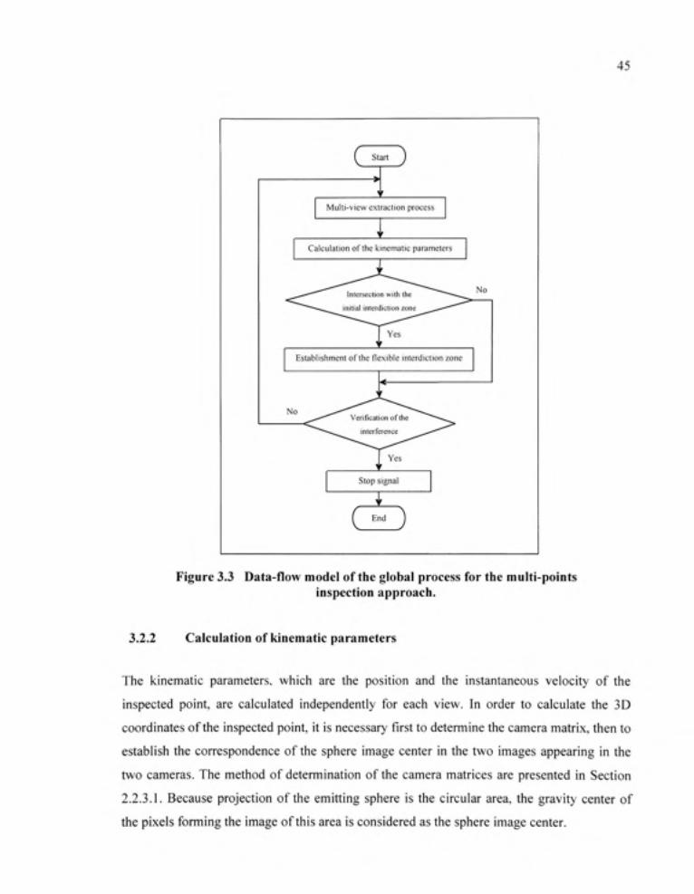
3.2 Algorith m
The multi-points inspection approach implies some change in the global process. Figure 3.3
shows the new global process.
3.2.1 Multi-vie w extraction proces s
The protective system uses at least one set of cameras for the upper view and the lower view.
Each camera set independently captures and sends the images of the emitting spheres to its
computer. Each sphere must emit an individual color for identification. The extraction
process is realized using the color threshold.
45
( star t J
Multi-view extraction process
Calculation of the kinematic parameters
Establishment of the flexible interdiction zone
Stop signal
( End J
Figure 3.3 Data-flo w model of the global process for the multi-points inspection approach.
3.2.2 Calculatio n of kinematic parameters
The kinematic parameters, which are the position and the instantaneous velocity of the
inspected point, are calculated independently for each view. In order to calculate the 3D
coordinates of the inspected point, it is necessary first to determine the camera matrix, then to
establish the correspondence of the sphere image center in the two images appearing in the
two cameras. The method of determination of the camera matrices are presented in Section
2.2.3.1. Because projection of the emitting sphere is the circular area, the gravity center of
the pixels forming the image of this area is considered as the sphere image center.
46
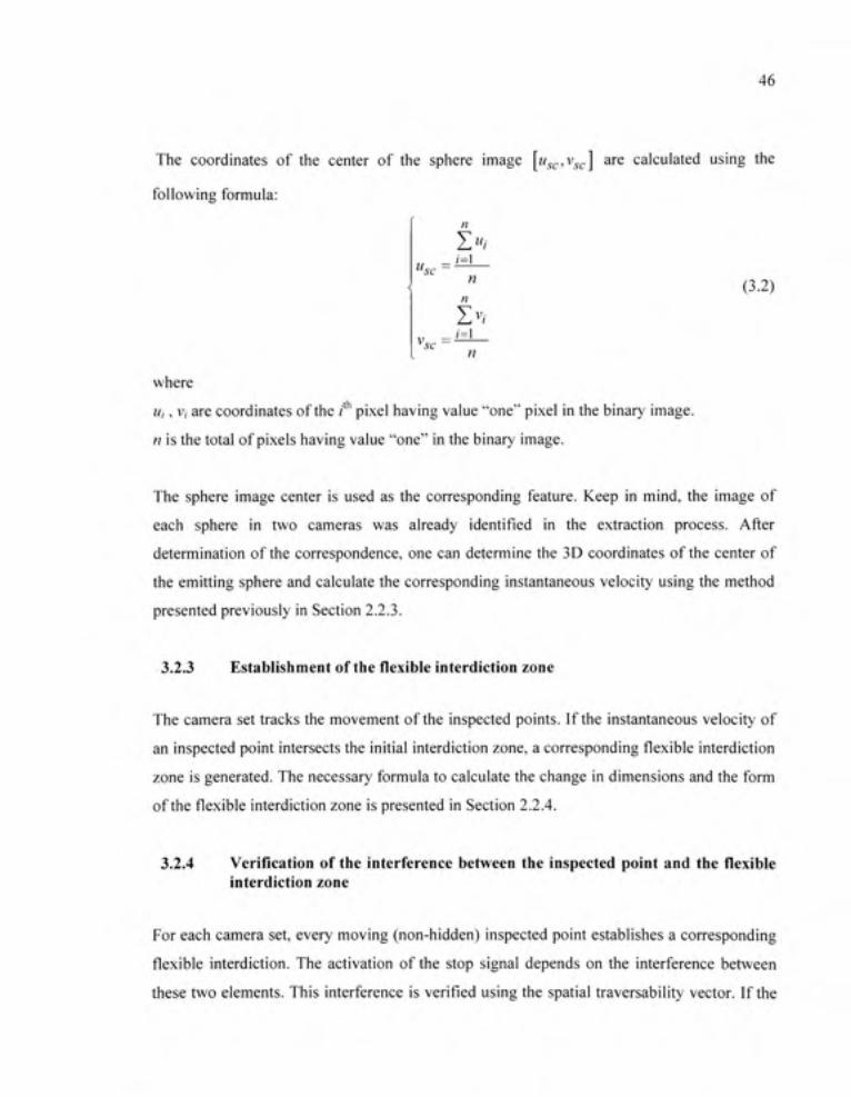
The coordinates of the center of the sphere image [w^c' ' ic] ^^^ calculated using the
following formula:
"sc
^sc
Z"; _ /= 1
n
n
Zv, ; = 1
(3.2)
n where
u,, V, are coordinates of the /* pixel having value "one" pixel in the binary image.
n is the total of pixels having value "one" in the binary image.
The sphere image center is used as the corresponding feature. Keep in mind, the image of
each sphere in two cameras was already identified in the extraction process. After
determination of the correspondence, one can determine the 3D coordinates of the center of
the emitting sphere and calculate the corresponding instantaneous velocity using the method
presented previously in Section 2.2.3.
3.2.3 Establishmen t o f the flexible interdiction zon e
The camera set tracks the movement of the inspected points. If the instantaneous velocity of
an inspected point intersects the initial interdiction zone, a corresponding flexible interdiction
zone is generated. The necessary formula to calculate the change in dimensions and the form
of the flexible interdiction zone is presented in Section 2.2.4.
3.2.4 Verificatio n o f the interferenc e betwee n th e inspecte d poin t an d th e flexible interdiction zon e
For each camera set, every moving (non-hidden) inspected point establishes a corresponding
flexible interdiction. The activation of the stop signal depends on the interference between
these two elements. This interference is verified using the spatial traversability vector. If the

47
inspected point is inside the corresponding fiexible interdiction zone, the corresponding
spatial traversability vector will have a known value. At this moment, the stop signal
reasoned by this interference is activated.
Keeping in mind that there are as many inspected points as the number of the emitting
spheres on the bracelet; and each inspected point can generate a stop signal in case of
interference. The first activated stop signal will stop the machine.
3.3 Experimental
3.3.1 Test bench
The test bench was modified in order to work with the multi-point inspection system. Figure
3.4 shows the modified test bench. The main difference is in the vision system that consisted
of two digital stereo heads, filters, and the emitting spheres (color electrical bulbs) which
were fixed on the mechanical hands.
Figure 3.4 Th e modified test bench.
Figure 3.5 shows a mechanical hand equipped with two electrical bulbs of different colors.

48
Figure 3.5 Th e emitting spheres.
3.3.1.1 Th e processing time
The average time for a global processing cycle per sphere, without considering the image
acquisition time, was 0.2s with 640x480 pixels resolution.
3.3.2 Th e extraction proces s
The first step of the global process is extraction of the spheres from the captured image.
Figure 3.6 presents the spheres and their corresponding binary images after the extraction
process. The experiment was performed with a mechanical hand. In this case, a sphere is
occulted by the wrist.
(a) (b) (c )
Figure 3.6 Th e extraction process . (d)
(a) the actual emitting spheres. (b) the filtered image of the emitting spheres. (c) (d) the corresponding images of the emitting spheres after the extraction process.
49
It was observed that with this multi-point inspection system it is possible to track many
inspected points at the same time. Figure 3.6 shows that in the case of three emitting spheres,
it was possible to identify two of them.
3.4 Results
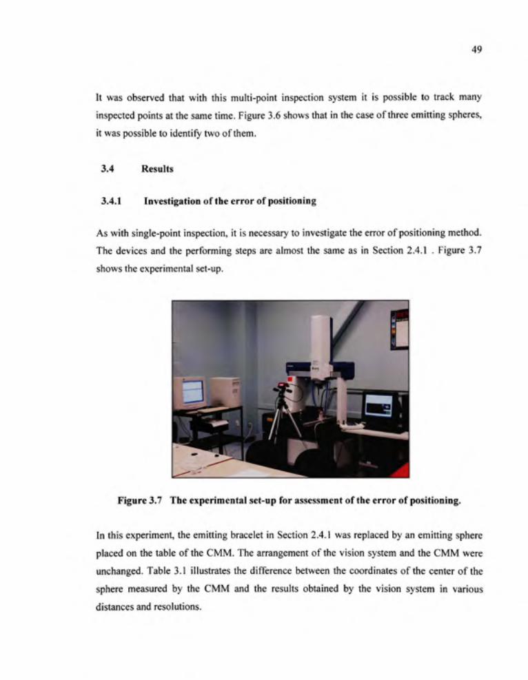
3.4.1 Investigatio n of the error of positioning
As with single-point inspection, it is necessary to investigate the error of positioning method.
The devices and the performing steps are almost the same as in Section 2.4.1 . Figure 3.7
shows the experimental set-up.
3* ^ f f %^m\ Ai// 1^ 1 i M
^ " ^ _
Figure 3.7 Th e experimental set-up for assessment of the error of positioning.
In this experiment, the emitting bracelet in Section 2.4.1 was replaced by an emitting sphere
placed on the table of the CMM. The arrangement of the vision system and the CMM were
unchanged. Table 3.1 illustrates the difference between the coordinates of the center of the
sphere measured by the CMM and the results obtained by the vision system in various
distances and resolutions.

50
Table 3.1 The difference between the coordinates measured by the coordinate measuring machine and
the results obtained by the vision system in various distances and resolutions.
Distance
-700 mm
-800 mm
-900 mm
-1000 mm
Measured by the CMM
1* V, :|*
(1)
[366±0.5, 53±0.5, 209±0.5]
[366±0.5, 176±0,5,209±0.5]
[366±0.5, 279±0.5, 209±0.5]
[366±0.5, 375±0.5, 209±0.5]
Resolution 1280x96 0
lx,y, z\'
(2)
[368±0.3, 59±0.5, 206±0.3]
[367±0.3, 181±0.5, 207±0.3]
[367±0.3, 283±0.5, 207±0.3]
[368±0.3, 383±0.5, 206±0.3]
Resolution 640x480
lx,y, zr
(3)
[369±0.3, 67±0.5, 202±0.3]
[368±0.3, 185±0.5,203±0.3]
[369±0.3, 291±0.5, 202±0.3]
[371±0.3, 392±0.5,200±0.3]
Difference**
|A.v, Av, A;)*
(4) = ( l ) - (2)
[-2, -6, 3]
[-1.-5,2]
[-1,-4.2]
[-2, -8, 3]
Difference**
|Ax, Av, AzI*
(5) = ( l )-(3)
[-3,-14,7]
[-2. -9, 6]
[-3,-12,7]
[-5,-17,9]
* in mm
** difference between the mean values
The resuhs in Table 3.1 show the influence of the distance separating the stereo head and the
sphere, and the influence of the image resolution on the precision of the positioning method.
The first factor plays a negative role, whereas the second factor is directly proportional to the
precision. Comparing Table 3.1 and Table 2.3 confirms the superiority of the second
approach where the center of the emitting sphere was used as the inspected point, instead of
the center of the emitting bracelet. It was demonstrated [22] that in certain specific situation,
the location of the bracelet image center (the center of the approximated ellipse) did not
coincide with the projection of the bracelet center.
3.4.2 Investigatio n of the error of the velocity magnitud e
Similar to Section 2.4.2, the error of the velocity magnitude of the inspected point was
performed by comparing the velocity magnitude of the center of the sphere by two different
methods.
Figure 3.8 shows the experimental set-up allowing comparing of a known velocity of the
inspected point with the results calculated by the vision system. In this experiment, an
emitting sphere was placed on the table of the motorized linear positioner with controllable
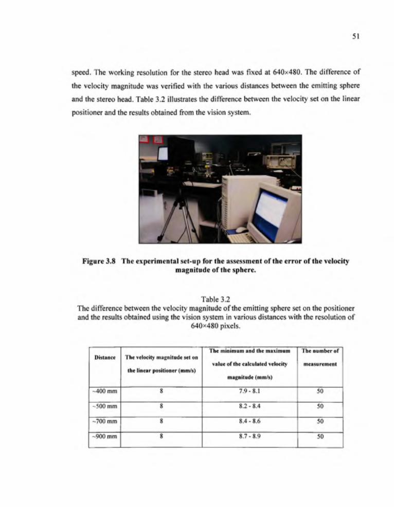
51
speed. The working resolution for the stereo head was fixed at 640x480. The difference of
the velocity magnitude was verified with the various distances between the emitting sphere
and the stereo head. Table 3.2 illustrates the difference between the velocity set on the linear
positioner and the resuhs obtained from the vision system.
Figure 3.8 Th e experimental set-up for the assessment of the error of the velocity magnitude of the sphere.
Table 3.2 The difference between the velocity magnitude of the emitting sphere set on the positioner and the resuhs obtained using the vision system in various distances with the resolution of
640x480 pixels.
Distance
-400 mm
-500 mm
-700 mm
-900 mm
The velocity magnitude set on
the linear positioner (mm/s)
8
8
8
8
The minimum and the maximum
value of the calculated velocity
magnitude (mm/s)
7.9-8.1
8.2 - 8.4
8.4 - 8.6
8.7-8.9
The number of
measurement
50
50
50
50

52
Column (3) of Table 3.2 shows that the precision of the measured velocity magnitude
decreases with the distance between the stereo head and the emitting sphere. It is also
observed that the difference between the maximum and the minimum values is smaller for
this approach, in comparison with the previous one. Again, this amelioration might come
from the better precision of the >» coordinate in the positioning step.
3.5 Conclusio n
Chapter three presents the investigation of a different approach for the flexible protective
system for press-brakes with multi-point scheme. In this system, the movement of each
worker's hand is inspected by some inspected points attached on the wrist. Precision is
higher when the inspected point is the center of the emitting sphere, than when it is the center
of the emitting bracelet. The disadvantage of the approach lies in the increase in processing
time due to the increase in the number of the inspected points.

CONCLUSION
The purpose of this thesis is to present a new principle, primarily aimed to improve existing
protective systems for hydraulic press-brakes. The new system must have the ability to
recognize situations in which it is not necessary to stop the machines, which is lacking in the
actual protective systems. The validity of the principle for such a system is proven in
Chapters 3 and 4 of the thesis. The new theory is based on determination of the direction of
movement of one or several inspected point(s) on the worker's hand. This would serve to
eliminate machine stoppage in cases which are not actually dangerous, and also to create a
protective zone capable of changing the protection volume according to the velocity of the
inspected point, in order to stop the machine appropriately, in cases of increased speed of the
inspected point towards the area defined as the dangerous zone.
In order to fiilfill this purpose, certain criteria were deemed necessary for the design of the
protective system for press-brakes. The criteria are as follows :
- recognition of cases in which the movement of the worker's hand actually poses danger,
based on the direction of the velocity of the inspected point;
usage of the velocity vector of the movement of the inspected point having dangerous
direction, to determine the necessary dimensions of the protective zone, in order to make
this zone more suitable. The magnitude of the velocity vector of the inspected point is the
second factor taken into consideration;
- system must make the decision to stop the machine automatically, based on the relation
between the position of the inspected point and the outline of the protective zone.
The experimental results prove the capability of vision technology to determine the kinematic
parameters of the inspected point.
Theoretically, two definitions concerning the inspected point have been presented. According
to the first definition, the center of the emitting bracelet is the inspected point. In the second
definition, the center of the emitting sphere is the inspected point. Both methods permit

54
capturing the image of the emitting bracelet and the emitting sphere on the sensor of the
camera in a stable fashion.
Another problem, which has been resolved, is the guarantee that the inspected point be
tracked continuously by the protective system. Several camera sets are distributed at viewing
locations where there is a possibility that the inspected point may be hidden during machine
operation. Specifically, distribution of the camera sets must guarantee continuous inspection
of the inspected point by at least one camera set, at all times.
In theory, the form of the flexible protective zone is decided based on the direction of the
velocity vector of the inspected point. Equation (2.9) is proposed for determination of this
zone. This equation integrates the velocity vector of the inspected point, as well as the
constants relating to the process of stopping the machine punch, into the establishment of the
flexible protective zone.
The mathematical tool used for making the decision to stop the machine, namely
traversibility vector, has been modified for application in 3D situations. This tool is used to
verify the entry of the inspected point into the protective zone and simplifies the task of
verification.
Concerning the investigation of the error of positioning, the results measured by visual
method were verified with the values measured by CMM of Mitutoyo. For the investigation
of the error of magnitude of the velocity vector, the resuhs measured by visual technique
were also verified with the resuhs measured by the positioner.
In the case of the emitting bracelet, measurement of the position of the inspected point using
the vision technique, at a distance of 900mm, under 1280x960 pixels resolution,
demonstrated a difference of 10mm on the>' coordinate, compared with the value measured
by CMM. In the method using the emitting sphere, this difference was 4mm. In addition, the

55
experiments also show that the resolution of the camera is an important factor in increasing
precision. Increasing the resolution significantly improves the precision of location.
The average magnitude of the velocity vector, measured using vision technology, with the
emitting bracelet at a distance of 900mm, under 640x480 pixels resolution, had a difference
of 9% compared with the set speed of the positioner. In the method using the emitting sphere,
this difference was 10%.
Tends of development
The proposed protective system is presented by the approaches and the primary experiments.
Even though the prospects applying the system in practice, it could be upgraded in fiature
according to some directions as follows :
- improvement of the processing time of the system;
- manufacture of the glove attaching the emitting bracelets or the emitting spheres.

APPENDIX I
SHAPES OF THE FLEXIBLE INTERDICTION ZONE
Instantaneous vectors and the corresponding flexible interdiction zones, the black lines
represent the initial interdiction zone, while the bold lines (both blue and black) represent the
flexible interdiction zone.

APPENDIX I I
SOURCE CODE OF FUNCTIONS
Capture images
% Capture 2 images of the stereo head
% Set the initial parameters
% Save 2 images to matrices
function [left,right]=layanhSVS
cmat('init');
cmat('open');
cmat('setSize',640,480);
cmat('setRate',30);
cmat('setColor',l,l);
cmat('setRect',l);
cmat('start');
left=zeros(480,640,3);
right=zeros(480,640,3);
cmat('getlmage',left,right);
left = uint8(round(left*255));
right = uint8(round(right*255));
cmat('stop');
cmat('close');

58
Extraction of the emitting object by the method of color threshold
% Extract objects to the binary images
% Known thresholds
fiinction [Outputimagel ,Output_image2]=tachobject(left,right)
rl=left(:,:,l);
gl=left(:,:,2);
bl=left(:,:,3);
Outputimagel = roicolor(r 1,200,255).'^roicolor(g 1,100,180).*roicolor(b 1,30,120);
r2=right(:,:,l);
g2=right(:,:,2);
b2=right(:,:,3);
Output_image2 = roicolor(r2,200,255).*roicolor(g2,100,180).*roicolor(b2,30,120);
Determination o f the coordinates of the center of the fitting ellipse
% Approximating bracelet to an ellipse
% Determining the center of the ellipse
function [Cx,Cy]=tinhtoadotamellipse_fitting(Output_image_f)
% Build the design matrix
[m,n]=size(Output_image_f);
ee=0;
for i=l:m
forj=l:n
if (Output_image_f(i,j)~=0)
59
ee=ee-)-l;
Dl(ee,l)=i^2;
Dl(ee,2)=i*j;
Dl(ee,3)=j^2;
D2(ee,l)=i;
D2(ee,2)=j;
D2(ee,3)=l;
end
end
end
% Build the scatter matrix
S1=D1'*D1
S2=D1'*D2
S3=D2'*D2
% T,M
T=- inv(S3)*S2';
M=SI+S2*T;
M=[M(3,:)./2;-M(2,:);M(l,:)./2];
% Eigenvalues , Calcul a
[evec,eval]=eig(M);
cond=4*evec(l,:) .* evec(3,:) - evec(2,:) .^2;
al=evec(:, find(cond>0));
a=[al;T*al];

60
% Center coordinate C(Cx,Cy)
Cx=((a(2)*a(5)-2*a(3)*a(4))/(4*a(l)*a(3)-(a(2)'^2)));
Cy=((a(2)*a(4)-2*a(l)*a(5))/(4*a(l)*a(3)-(a(2)^2)));
Determination o f the camera matrice s
% Determining 2 camera matrices of the stereo head
% Input data
% 3D coordinates of the calibration object
x=[149.6 60.9 60.9 149.6 149.4 60.7 60.9 149.4 150.5 61.8 61.8 150.5 150.7 62 62 150.7
151.7 62 63.3 152 152.6 64.164.2 153];
y=[36.7 36.7 63 62.2 96.3 96.7 121.6 121.7 155.2 155.6 181.5 180.7 245.9 246.9 272.7 271.9
310.3 311.3 337 336 370.7 371.4 397 396.5];
z=[86.3 85.9 93.9 93.9 104.7 104.8 113 113 124 123.5 132 132.1 133.4 133.3 125.2 125.4
113 112.8 104.5 104.8 93.6 93.4 85.6 85.9];
% 2D location of the corners of the left camera
ul=[540 540 518 519 490 488 464 465 433 433 405 406 336 336 305 306 267 266 238 239
206 205 180 180]; %Left
vl=[197 286 286 196 195 289 289 195 193 290 290 193 192 290 290 192 192 287 286 192
192 284 283 192];
% 2D location of the comers of the right camera
u2=[474 474 448 450 418 416 390 390 356 356 326 327 256 255 228 228 192 190 166 165
136 135 111 111]; %Right
v2=[183 273 275 182 181 276 276 181 179 277 278 179 178 277 276 178 178 273 272 178
178 269 268 178];

61
n=24;
j=i ;
% Transform matrix of 1 st camera
for i=l:n
A10,:)=[x(i) y(i) z(i) 10 0 0 0 -(x(i)*ul(i)) -(y(i)*ul(i)) -(z(i)*ul(i))];
Aia+1,:)=[0 0 0 0 x(i) y(i) z(i) 1 -(x(i)*vl(i)) -(y(i)*vl(i)) -(z(i)*vl(i))];
B10)=ul(i);
B10+l)=vl(i);
j=2*i+l;
end
Cl=(inv(Al'*Al))*Al'*(Bl');
R1=B1'-A1*C1;
% Transform matrix of 2nd camera
for i=l:n
A20,:)=[x(i) y(i) z(i) 10 0 0 0 -(x(i)*u2(i)) -(y(i)*u2(i)) -(z(i)*u2(i))];
A2a+1,:)=[0 0 0 0 x(i) y(i) z(i) 1 -(x(i)*v2(i)) -(y(i)*v2(i)) -(z(i)*v2(i))];
B2a)=u2(i);
B2a+l)=v2(i);
j=2*i+l;
end
C2=(inv(A2'*A2))*A2'*(B2');
R2=B2'-A2*C2;

62
Determination o f the 3D coordinates of the inspected poin t
% 3D coordinates of the inspected point was determined by using 2D ellipse center
coordinates and the camera matrices
function [TD]=tinhtoado3D(Cxl,Cyl,Cxr,Cyr)
uu(l) = Cyl;
vv(l) = Cxl;
uu(2) = Cyr;
vv(2) = Cxr;
% 3D coordinates
% Points Pl(z=3), P2(z=10)
ATC1=[C1(1)-Cl(9)*uu(l) Cl(2)-Cl(10)*uu(l); Cl(5)-Cl(9)*vv(l) Cl(6)-Cl(10)*vv(l)];
BTCl=[uu(l)-Cl(4)-(Cl(3)-Cl(ll)*uu(l))*3;vv(l)-Cl(8)-(Cl(7)-Cl(ll)*vv(l))*3];
XTCl=(inv(ATCl))*BTCl;
PI=[XTC1(1);XTC1(2);3];
ATC1=[C1(1)-Cl(9)*uu(l) Cl(2)-Cl(10)*uu(l); Cl(5)-CI(9)*vv(l) Cl(6)-Cl(10)*vv(l)];
BTCl=[uu(l)-Cl(4)-(Cl(3)-Cl(ll)*uu(l))*10;vv(l)-Cl(8)-(Cl(7)-Cl(ll)*vv(l))*10];
XTCl=(inv(ATCl))*BTCl;
P2=[XTC1(1);XTC1(2);10];
P1P2=P2-P1;
% Points Ql(z=3), Q2(z=10)
ATC2=[C2(1)-C2(9)*uu(2) C2(2)-C2(10)*uu(2); C2(5)-C2(9)*vv(2) C2(6)-C2(10)*vv(2)];
BTC2=[uu(2)-C2(4)-(C2(3)-C2(l l)*uu(2))*3; vv(2)-C2(8)-(C2(7)-C2(l l)*vv(2))*3];

63
XTC2=(inv(ATC2))*BTC2;
Q1=[XTC2(1);XTC2(2);3];
ATC2=[C2(1)-C2(9)*uu(2) C2(2)-C2(10)*uu(2); C2(5)-C2(9)*vv(2) C2(6)-C2(10)*vv(2)]:
BTC2=[uu(2)-C2(4)-(C2(3)-C2(l l)*uu(2))*10; vv(2)-C2(8)-(C2(7)-C2(l l)*vv(2))*10];
XTC2=(inv(ATC2))*BTC2;
Q2=[XTC2(1); XTC2(2);10];
Q1Q2=Q2-Q1;
% Calculation of al, a2
P1Q1=Q1-P1;
AF=[dot(P 1 P2,P 1P2) -(dot(P 1 P2,Q 1Q2)) ;dot(P 1 P2,Q 1Q2) -(dot(Q 1 Q2,Q 1Q2))];
BF=[dot(P 1Q1 ,P 1 P2);dot(P 1Q1 ,Q 1Q2)];
XF=(inv(AF))*BF;
al=XF(l);
a2=XF(2);
% 3D coordinates
V=P1 + al*PlP2 -(Ql +a2*QlQ2);
% V: shortest vector connecting the two lines
MV=sqrt(dot(V,V))
% Module of V for verifying error in corresponding image points
TD=0.5*((Pl+al*PlP2) + (Ql+a2*QlQ2));
% Display coordinates of the inspected point (3D coordinates)

64
Verification o f th e conditio n intersectio n o f th e instantaneou s vecto r o f th e inspecte d
point with the initial interdiction zon e
fiinction [cat]=check(xl,yl,zl,x2,y2,z2,iz_x,iz_y,iz_z)
% Data of 6 planes
a=iz_x; % plan intersect with x axes
b=iz_y; % plan intersect with y axes
c=iz_z; % plan intersect with z axes
x(l)=xl;
y(l)=yl;
z(l)=zl;
x(2)=x2
y(2)=y2
z(2)=z2
% Check of intersection
dk=0;
% dk=l having intersection , dk=0 not intersecting between vector and one of five planes
% MPl: z=0 , 0 <= X <=a , 0 <= y <=b
xmpl=x(l) + (x(2)-x(l))*(-z(l))/(z(2)-z(l));
ympl=y(l) + (y(2)-y(l))*(-z(l))/(z(2)-z(l));
if (0<=xmpl)&(xmpl<=a)«fe(0<=ympl)&(ympl<=b) dk(l)=l; else dk(l)=0; end
65
% MP2: y=b , 0 <= x <=a, 0 <= z <=c
xmp2=x(l) + (x(2)-x(l))*(b-y(l))/(y(2)-y(l));
zmp2=z(l) + (z(2)-z(l))*(b-y(l))/(y(2)-y(l));
if (0<=xmp2)&(xmp2<=a)&(0<=zmp2)«&(zmp2<=c) dk(2)=l; else dk(2)=0; end
% MP3: z=c , 0 <= X <=a , 0 <= y <=b
xmp3=x(l) + (x(2)-x(l))*(c-z(l))/(z(2)-z(l));
ymp3=y(l) + (y(2)-y(l))*(c-z(l))/(z(2)-z(l));
if (0<=xmp3)&(xmp3<=a)&(0<=ymp3)&(ymp3<=b) dk(3)=l; else dk(3)=0; end
% MP4: y=0 , 0 <= x <=a , 0 <= z <=c
xmp4=x(l) + (x(2)-x(l))*(-y(l))/(y(2)-y(l));
zmp4=z(l) + (z(2)-z(l))*(-y(l))/(y(2)-y(l));
if (0<=xmp4)&(xmp4<=a)&(0<=zmp4)&(zmp4<=c) dk(4)=l; else dk(4)=0; end
% MP5: x=a , 0 <= y <=b , 0 <= z <=c
ymp5=y(l) + (y(2)-y(l))*(a-x(l))/(x(2)-x(l));
zmp5=z(l) + (z(2)-z(l))*(a-x(l))/(x(2)-x(l));
if (0<=ymp5)«fe(ymp5<=b)&(0<=zmp5)&(zmp5<=c) dk(5)=l; else dk(5)=0; end
if (dk(l)==0)&(dk(2)==0)&(dk(3)==0)&(dk(4)==0)«&(dk(5)==0) cat=0; else cat=l; end
end

66
Establishment of the flexible interdiction zon e
% Calculation of new coordinates of a point establishing the flexible interdiction zone
% citx X coordinate of the vector of dimension change
% i is the case corresponding to the direction of the instantaneous vector of the inspected
point
% a,b,c is 3 dimensions of the initial interdiction zone
function [dnx,dny,dnz]=toadomoi(citx,city,citz,i,a,b,c)
% New coordinates
switch i
case 1
dnx=-citx -I- a;
dny=-city;
dnz=-citz;
case 2
dnx=-citx -I- a;
dny=-city -I- b;
dnz=-citz;
case 3
dnx=-citx -I- a;
dny=-city -I- b;
dnz=-citz + c;
case 4
dnx=-citx -I- a;
dny=-city;
dnz=-citz -I- c;
case 5

67
dnx=
dny
dnz=
case 6
dnx-
dny=
dnz=
case 7
dnx=
dny=
dnz=
case 8
dnx=
dny
dnz
end
citx;
-city;
-citz;
-citx;
-city + b;
citz;
•citx;
•city -I- b ;
•citz + c;
-citx;
-city;
-citz + c;
function [vecint,xdirec,ydirec,zdirec]=vectorflexible(xl,yl,zl,x2,y2,z2,ti)
% Data
% Coordinates of 2 points creating the displacement vector of the inspected point
x(l)=xl;
y(l)=yl;
z(l)=zl;
x(2)=x2;
y(2)=y2;
z(2)=z2;
t=ti;
68
% The interval time performing the displacement of the inspected point
t_response=0.18; % Response time of the stop system
t_img=0.2; % Maximum processing time of vision
k=l;
% Tinh vector flexible
vit=[(x2-x 1 )/t;(y2-y 1 )/t;(z2-z 1 )/t];
% Velocity vector
m_v it=sqrt(dot( V it, v it));
% Magnitude of velocity vector
m_cit=k*(t_response-l- t_img)*m_vit;
% Magnitude of the dimension change vector
vecint=m_cit;
% Dimension change vector
xdirec=(x2-xl )/(t'''m_vit);
ydirec=(y2-yl)/(t*m_vit);
zdirec=(z2-zl)/(t*m_vit);
% Direction of the dimension change vector (normaled)
Verification o f the interference betwee n the inspected poin t and the flexible interdictio n
zone
fiinction [stop]=check_inside_flexible(xl,yl,zl,x2,y2,z2,ti,iz_x,iz_y,iz_z)

69
% Input
a=iz_x;
b=iz_y;
c=iz_z;
x(l)=xl;
y(l)=yl;
z(l)=zl;
x(2)=x2;
y(2)=y2;
z(2)=z2;
t=ti;
% Code_cit
code_cit=10;
dk=0;
cit=[(x2-xl)/t;(y2-yl)/t;(z2-zl)/t];
citt=[0;0;0];
fori=l:3
if(cit(i)<0)citt(i)=-l;end
if(cit(i)>0)citt(i)=l;end
end
[cat]=check(xl ,y 1 ,z 1 ,x2,y2,z2,a,b,c)
% cat=l having intersection, cat=0 not intersecting between vector and one of five planes

70
switch cat
case 1
if citt==[-l;0;0] code_cit=l;
elseif citt==
elseif citt==
elseif citt
elseif citt==
elseif citt=
elseif citt=
elseif citt=
elseif citt=
elseif citt==
elseif citt==
elseif citt==
elseif citt==
else code_cit=14; end
otherwise
code_cit=14;
end
[-1;1;1] code_cit=2;
[-1;1;-1] code_cit=3;
[0;l;0]code_cit=4;
[0;0;-l]code_cit=5;
[-1;-1;I] code_cit=6;
[-1;-1;-1] code_cit=7;
[0;-l;0]code_cit=8;
[0;0;1] code_cit=9;
[-l;l;0]code_cit=10;
[-l;-l;0]code_cit=ll;
[-l;0;-l]code_cit=12;
[-l;0;l]code_cit=13;
% Check condition of interference
% Code values of cit, having 27 cases of cit, only consider with
% 8 cases, those cases when it is considered that the flexible dangerous zone is the initial
interdiction zone
switch codecit
case 1
[vecint,xdirec,ydirec,zdirec]=vectorflexible(xl,yl,zl,x2,y2,z2,ti);
cit=[vecint*xdirec;vecint*ydirec;vecint*zdirec];
71
[dnx 1 ,dny 1 ,dnz 1 ]=toadomoi(cit( 1 ),cit(2),cit(3), 1 ,a,b,c);
[dnx2,dny2,dnz2]=toadomoi(cit(l),cit(2),cit(3),2,a,b,c);
[dnx3,dny3,dnz3]=toadomoi(cit(l),cit(2),cit(3),3,a,b,c);
[dnx4,dny4,dnz4]=toadomoi(cit(l),cit(2),cit(3),4,a,b,c);
[al]=diem_matphang(x(2),y(2),z(2),a,0,0,a,b,0,0,b,0);
[a2]=diem_matphang(x(2),y(2),z(2),a,b,c,a,b,0,0,b,0);
[a3]=diem_matphang(x(2),y(2),z(2),a,0,c,a,b,c,0,b,c);
[a4]=diem_matphang(x(2),y(2),z(2),a,0,0,a,0,c,0,0,c);
[anf5]=diem_matphang(x(2),y(2),z(2),dnxl,dnyl,dnzl,dnx2,dny2,dnz2,dnx3,dny3,dnz3);
[a6]=diem_matphang(x(2),y(2),z(2),0,b,0,0,b,c,0,0,c);
if (0<al)&(0>a2)&(0>a3)&(0>a4)&(0>anf5)&(0<a6) dk=l; else dk=0; end
% dk=l
% inside
case 2
[vecint,xdirec,ydirec,zdirec]=vectorflexible(xl,yl,zl,x2,y2,z2,ti);
cit=[vecint*xdirec;vecint*ydirec;vecint*zdirec]
[dnx 1 ,dny 1 ,dnz 1 ]=toadomoi(cit( 1 ),cit(2),cit(3), 1 ,a,b,c)
[dnx2,dny2,dnz2]=toadomoi(cit( 1 ),cit(2),cit(3),2,a,b,c)
[dnx3,dny3,dnz3]=toadomoi(cit(l),cit(2),cit(3),3,a,b,c)
[dnx4,dny4,dnz4]=toadomoi(cit( 1 ),cit(2),cit(3),4,a,b,c)
[dnx5,dny5,dnz5]=toadomoi(cit(l),cit(2),cit(3),5,a,b,c)
[dnx6,dny6,dnz6]=toadomoi(cit( 1 ),cit(2),cit(3),6,a,b,c)
[dnx8,dny8,dnz8]=toadomoi(cit( 1 ),cit(2),cit(3),8,a,b,c)

72
[a2]=diem_matphang(x(2),y(2),z(2),a,b,0,a,b,c,0,b,c);
[a3]=diem_matphang(x(2),y(2),z(2),a,b,c,a,0,c,0,0,c);
[a6]=diem_matphang(x(2),y(2),z(2),0,b,0,0,b,c,0,0,c);
[anl4]=diem_matphang(x(2),y(2),z(2),dnx5,dny5,dnz5,dnx8,dny8,dnz8,dnx4,dny4,dnz4);
[anl6]=diem_matphang(x(2),y(2),z(2),dnx5,dny5,dnz5,dnx8,dny8,dnz8,0,0,c);
[anl3]=diem_matphang(x(2),y(2),z(2),dnx4,dny4,dnz4,dnx8,dny8,dnz8,0,0,c);
[anf2]=diem_matphang(x(2),y(2),z(2),dnx2,dny2,dnz2,dnx3,dny3,dnz3,a,b,c);
[anO]=diem_matphang(x(2),y(2),z(2),dnx3,dny3,dnz3,dnx4,dny4,dnz4,a,0,c);
[anf5]=diem_matphang(x(2),y(2),z(2),dnxl,dnyl,dnzl,dnx2,dny2,dnz2,dnx3,dny3,dnz3);
[andl]=diem_matphang(x(2),y(2),z(2),dnxl,dnyl,dnzl,dnx2,dny2,dnz2,dnx6,dny6,dnz6);
[and2]=diem_matphang(x(2),y(2),z(2),dnx2,dny2,dnz2,dnx6,dny6,dnz6,0,b,0);
[and6]=diem_matphang(x(2),y(2),z(2),dnx5,dny5,dnz5,dnx6,dny6,dnz6,0,b,0);
if
(0<a2)&(0<a3)&(0<a6)&(0<anl4)&(0>anl6)&(0<anl3)&(0<anf2)&(0<anf3)&(0>anf5)&(0<
andl)&(0>and2)&(0<and6) dk=l; else dk=0; end
case 3
[vecint,xdirec,ydirec,zdirec]=vectorflexible(x 1 ,y 1 ,z 1 ,x2,y2,z2,ti);
cit=[vecint*xdirec;vecint*ydirec:vecint*zdirec];
[dnxl ,dny 1 ,dnz 1 ]=toadomoi(cit( 1 ),cit(2),cit(3), 1 ,a,b,c);
[dnx2,dny2,dnz2]=toadomoi(cit(l),cit(2),cit(3),2,a,b,c);
[dnx3,dny3,dnz3]=toadomoi(cit(l),cit(2),cit(3),3,a,b,c);
[dnx4,dny4,dnz4]=toadomoi(cit(l),cit(2),cit(3),4,a,b,c);

73
[dnx5,dny5,dnz5]=toadomoi(cit(l),cit(2),cit(3),5,a,b,c);
[dnx7,dny7,dnz7]=toadomoi(cit(l),cit(2),cit(3),7,a,b,c);
[dnx8,dny8,dnz8]=toadomoi(cit(l),cit(2),cit(3),8,a,b,c);
[al]=diem_matphang(x(2),y(2),z(2),a,0,0,a,b,0,0,b,0);
[a2]=diem_matphang(x(2),y(2),z(2),a,b,0,a,b,c,0,b,c);
[a6]=diem_matphang(x(2),y(2),z(2),0,b,0,0,b,c,0,0,c);
[anu2]=diem_matphang(x(2),y(2),z(2),dnx3,dny3,dnz3,dnx7,dny7,dnz7,0,b,c);
[anu3]=diem_matphang(x(2),y(2),z(2),dnx3,dny3,dnz3,dnx7,dny7,dnz7,dnx8,dny8,dnz8);
[anu6]=diem_matphang(x(2),y(2),z(2),dnx7,dny7,dnz7,dnx8,dny8,dnz8,0,0,c);
[anl 1 ]=diem_matphang(x(2),y(2),z(2),dnxl,dny 1 ,dnzl ,dnx5,dny5,dnz5,0,0,0);
[anl4]=diem_matphang(x(2),y(2),z(2),dnx5,dny5,dnz5,dnx8,dny8,dnz8,dnx4,dny4,dnz4);
[anl6]=diem_matphang(x(2),y(2),z(2),dnx5 ,dny 5 ,dnz5 ,dnx8,dny 8,dnz8,0,0,c);
[anfl]=diem_matphang(x(2),y(2),z(2),dnxl,dnyl,dnzl,dnx2,dny2,dnz2,a,b,0);
[anf2]=diem_matphang(x(2),y(2),z(2),dnx2,dny2,dnz2,dnx3,dny3,dnz3,a,b,c);
[anf5]=diem_matphang(x(2),y(2),z(2),dnxl,dnyl,dnzl,dnx2,dny2,dnz2,dnx3,dny3,dnz3)
if
(0<al )&(0<a2)&(0<a6)&(0<anu2)&(0>anu3)&(0<anu6)&(0>anl 1 )&(0<anl4)&(0>anl6)&(0
<ann)&(0<anf2)&(0>anf5) dk=l; else dk=0; end
case 4
[vecint,xdirec,ydirec,zdirec]=vectorflexible(xl,yl,zl,x2,y2,z2,ti);
cit=[vecint*xdirec;vecint*ydirec;vecint*zdirec];
[dnxl,dny 1 ,dnz 1 ]=toadomoi(cit( 1 ),cit(2),cit(3), 1 ,a,b,c);
[dnx4,dny4,dnz4]=toadomoi(cit( 1 ),cit(2),cit(3),4,a,b,c);

74
[dnx8,dny8,dnz8]=toadomoi(cit(l),cit(2),cit(3),8,a,b,c);
[al]=diem_matphang(x(2),y(2),z(2),a,0,0,a,b,0,0,b,0);
[a2]=diem_matphang(x(2),y(2),z(2),a,b,c,a,b,0,0,b,0);
[a3]=diem_matphang(x(2),y(2),z(2),a,0,c,a,b,c,0,b,c);
[anl4]=diem_matphang(x(2),y(2),z(2),dnxl,dnyl,dnzl,dnx4,dny4,dnz4,dnx8,dny8,dnz8);
[a5]=diem_matphang(x(2),y(2),z(2),a,0,c,a,b,0,a,b,c);
[a6]=diem_matphang(x(2),y(2),z(2),0,b,0,0,b,c,0,0,c);
if (0<al)«fe(0>a2)&(0>a3)&(0>anl4)&(0>a5)&(0<a6) dk=l; else dk=0; end
case 5
[vecint,xdirec,ydirec,zdirec]=vectorflexible(xl,yl,zl,x2,y2,z2,ti);
cit=[vecint*xdirec;vecint*ydirec;vecint*zdirec];
[dnx3,dny3,dnz3]=toadomoi(cit(l),cit(2),cit(3),3,a,b,c);
[dnx4,dny4,dnz4]=toadomoi(cit(l),cit(2),cit(3),4,a,b,c);
[dnx7,dny7,dnz7]=toadomoi(cit(l),cit(2),cit(3),7,a,b,c);
[al]=diem_matphang(x(2),y(2),z(2),a,0,0,a,b,0,0,b,0);
[a2]=diem_matphang(x(2),y(2),z(2),a,b,c,a,b,0,0,b,0);
[anu3]=diem_matphang(x(2),y(2),z(2),dnx4,dny4,dnz4,dnx3,dny3,dnz3,dnx7,dny7,dnz7);
[a4]=diem_matphang(x(2),y(2),z(2),a,0,0,0,0,0,0,0,c);
[a5]=diem_matphang(x(2),y(2),z(2),a,0,c,a,b,0,a,b,c);
[a6]=diem_matphang(x(2),y(2),z(2),0,b,0,0,b,c,0,0,c);
if (0<al)&(0>a2)&(0>anu3)&(0<a4)&(0>a5)&(0<a6) dk=l; else dk=0; end

75
case 6
[vecint,xdirec,ydirec,zdirec]=vectorflexible(x 1 ,y 1 ,z 1 ,x2,y2,z2,ti);
cit=[vecint*xdirec;vecint*ydirec;vecint*zdirec];
[dnxl,dny 1 ,dnz 1 ]=toadomoi(cit( 1 ),cit(2),cit(3), 1 ,a,b,c)
[dnx2,dny2,dnz2]=toadomoi(cit(l),cit(2),cit(3),2,a,b,c)
[dnx3,dny3,dnz3]=toadomoi(cit(l),cit(2),cit(3),3,a,b,c)
[dnx4,dny4,dnz4]=toadomoi(cit( 1 ),cit(2),cit(3),4,a,b,c)
[dnx5,dny5,dnz5]=toadomoi(cit(l),cit(2),cit(3),5,a,b,c)
[dnx6,dny6,dnz6]=toadomoi(cit(l),cit(2),cit(3),6,a,b,c)
[dnx7,dny7,dnz7]=toadomoi(cit( 1 ),cit(2),cit(3),7,a,b,c)
[a3]=diem_matphang(x(2),y(2),z(2),a,0,c,a,b,c,0,b,c);
[a4]=diem_matphang(x(2),y(2),z(2),a,0,0,0,0,0,0,0,c);
[a6]=diem_matphang(x(2),y(2),z(2),0,b,0,0,b,c,0,0,c);
[anr2]=diem_matphang(x(2),y(2),z(2),dnx3,dny3,dnz3,dnx7,dny7,dnz7,dnx6,dny6,dnz6);
[anr3]=diem_matphang(x(2),y(2),z(2),dnx3,dny3,dnz3,dnx7,dny7,dnz7,0,b,c);
[anr6]=diem_matphang(x(2),y(2),z(2),dnx7,dny7,dnz7,dnx6,dny6,dnz6,0,b,0);
[anf3]=diem_matphang(x(2),y(2),z(2),dnx3,dny3,dnz3,dnx4,dny4,dnz4,a,0,c);
[anf4]=diem_matphang(x(2),y(2),z(2),dnx 1 ,dny 1 ,dnz 1 ,dnx4,dny4,dnz4,a,0,c);
[anf5]=diem_matphang(x(2),y(2),z(2),dnxl,dnyl,dnzl,dnx2,dny2,dnz2,dnx3,dny3,dnz3);
[andl]=diem_matphang(x(2),y(2),z(2),dnxl,dnyl,dnzl,dnx2,dny2,dnz2,dnx6,dny6,dnz6);
[and4]=diem_matphang(x(2),y(2),z(2),dnx 1 ,dny 1 ,dnz 1 ,dnx5 ,dny 5 ,dnz5,0,0,0);
[and6]=diem_matphang(x(2),y(2),z(2),dnx5,dny5,dnz5,dnx6,dny6,dnz6,0,b,0);

76
if
(0>a3)«&(0<a4)&(0<a6)&(0<anr2)&(0>anr3)&(0>anr6)«&(0<anfi)&(0>anf4)«S:(0>anf5)«&(0<
andl)&(0<and4)&(0<and6) dk=l; else dk=0; end
case 7
[vecint,xdirec,ydirec,zdirec]=vectorflexible(xl,yl,zl,x2,y2,z2,ti);
cit=[vecint*xdirec;vecint*ydirec;vecint*zdirec];
[dnxl ,dny 1 ,dnz 1 ]=toadomoi(cit( 1 ),cit(2),cit(3), 1 ,a,b,c)
[dnx2,dny2,dnz2]=toadomoi(cit(l),cit(2),cit(3),2,a,b,c)
[dnx3,dny3,dnz3]=toadomoi(cit(l),cit(2),cit(3),3,a,b,c)
[dnx4,dny4,dnz4]=toadomoi(cit(l),cit(2),cit(3),4,a,b,c)
[dnx6,dny6,dnz6]=toadomoi(cit( 1 ),cit(2),cit(3),6,a,b,c)
[dnx7,dny7,dnz7]=toadomoi(cit( 1 ),cit(2),cit(3),7,a,b,c)
[dnx8,dny8,dnz8]=toadomoi(cit(l),cit(2),cit(3),8,a,b,c)
[al]=diem_matphang(x(2),y(2),z(2),a,0,0,a,b,0,0,b,0);
[a4]=diem_matphang(x(2),y(2),z(2),a,0,0,0,0,0,0,0,c);
[a6]=diem_matphang(x(2),y(2),z(2),0,b,0,0,b,c,0,0,c);
[anrl]=diem_matphang(x(2),y(2),z(2),dnx2,dny2,dnz2,dnx6,dny6,dnz6,0,b,0);
[anr2]=diem_matphang(x(2),y(2),z(2),dnx2,dny2,dnz2,dnx6,dny6,dnz6,dnx7,dny7,dnz7);
[anr6]=diem_matphang(x(2),y(2),z(2),dnx7,dny7,dnz7,dnx6,dny6,dnz6,0,b,0);
[anf 1 ]=diem_matphang(x(2),y(2),z(2),a,b,0,a,0,0,dnx 1 ,dny 1 ,dnz 1);
[anf4]=diem_matphang(x(2),y(2),z(2),dnx 1 ,dny 1 ,dnz 1 ,dnx4,dny4,dnz4,a,0,c);
[anf5]=diem_matphang(x(2),y(2),z(2),dnxl,dnyl,dnzl,dnx2,dny2,dnz2,dnx3,dny3,dnz3);
[anu3]=diem_matphang(x(2),y(2),z(2),dnx4,dny4,dnz4,dnx3,dny3,dnz3,dnx7,dny7,dnz7);
[anu4]=diem_matphang(x(2),y(2),z(2),dnx4,dny4,dnz4,dnx8,dny8,dnz8,0,0,c);

77
[anu5]=diem_matphang(x(2),y(2),z(2),dnx8,dny8,dnz8,dnx7,dny7,dnz7,0,b,c);
if
(0<al)&(0<a4)&(0<a6)&(0>anr2)«&(0>anr6)«S:(0<ann)&(0>anf4)&(0>anf5)&(0>anu3)«&(0
>anu4)&(0>anu5) dk=l; else dk=0; end
case 8
[vecint,xdirec,ydirec,zdirec]=vectorflexible(xl,yl,zl,x2,y2,z2,ti);
cit=[vecint*xdirec;vecint*ydirec;vecint*zdirec];
[dnx2,dny2,dnz2]=toadomoi(cit(l),cit(2),cit(3),2,a,b,c);
[dnx3,dny3,dnz3]=toadomoi(cit(l),cit(2),cit(3),3,a,b,c);
[dnx6,dny6,dnz6]=toadomoi(cit(l),cit(2),cit(3),6,a,b,c);
[al]=diem_matphang(x(2),y(2),z(2),a,0,0,a,b,0,0,b,0);
[anr2]=diem_matphang(x(2),y(2),z(2),dnx3,dny3,dnz3,dnx2,dny2,dnz2,dnx6,dny6,dnz6);
[a3]=diem_matphang(x(2),y(2),z(2),a,0,c,a,b,c,0,b,c);
[a4]=diem_matphang(x(2),y(2),z(2),a,0,0,0,0,0,0,0,c);
[a5]=diem_matphang(x(2),y(2),z(2),a,0,c,a,b,0,a,b,c);
[a6]=diem_matphang(x(2),y(2),z(2),0,b,0,0,b,c,0,0,c);
if (0<al)&(0>anr2)&(0>a3)&(0<a4)&(0>a5)«&(0<a6) dk=l; else dk=0; end
case 9
[vecint,xdirec,ydirec,zdirec]=vectorflexible(xl,yl,zl,x2,y2,z2,ti);
cit=[vecint*xdirec;vecint*ydirec;vecint*zdirec]
[dnx 1 ,dny 1 ,dnz 1 ]=toadomoi(cit( 1 ),cit(2),cit(3), 1 ,a,b,c);

78
[dnx2,dny2,dnz2]=toadomoi(cit( 1 ),cit(2),cit(3),2,a,b,c);
[dnx6,dny6,dnz6]=toadomoi(cit( 1 ),cit(2),cit(3),6,a,b,c);
[and 1 ]=diem_matphang(x(2),y(2),z(2),dnx 1 ,dny 1 ,dnz 1 ,dnx2,dny2,dnz2,dnx6,dny6,dnz6);
[a2]=diem_matphang(x(2),y(2),z(2),a,b,c,a,b,0,0,b,0);
[a3]=diem_matphang(x(2),y(2),z(2),a,0,c,a,b,c,0,b,c);
[a4]=diem_matphang(x(2),y(2),z(2),a,0,0,0,0,0,0,0,c);
[a5]=diem_matphang(x(2),y(2),z(2),a,0,c,a,b,0,a,b,c);
[a6]=diem_matphang(x(2),y(2),z(2),0,b,0,0,b,c,0,0,c);
if (0<andl)&(0>a2)&(0>a3)«&(0<a4)&(0>a5)«fe(0<a6) dk=l; else dk=0; end
case 10
[vecint,xdirec,ydirec,zdirec]=vectorflexible(x 1 ,y 1 ,z 1 ,x2,y2,z2,ti);
cit=[vecint*xdirec;vecint*ydirec;vecint*zdirec]
[dnx 1 ,dny 1 ,dnz 1 ]=toadomoi(cit( 1 ),cit(2),cit(3), 1 ,a,b,c)
[dnx2,dny2,dnz2]=toadomoi(cit( 1 ),cit(2),cit(3),2,a,b,c)
[dnx3,dny3,dnz3]=toadomoi(cit(l),cit(2),cit(3),3,a,b,c)
[dnx4,dny4,dnz4]=toadomoi(cit( 1 ),cit(2),cit(3),4,a,b,c)
[dnx5,dny5,dnz5]=toadomoi(cit(l),cit(2),cit(3),5,a,b,c)
[dnx8,dny8,dnz8]=toadomoi(cit(l),cit(2),cit(3),8,a,b,c)
[al]=diem_matphang(x(2),y(2),z(2),a,0,0,a,b,0,0,b,0);
% Khong can thiet lam , chi de tao ra convex polygon
[a2]=diem_matphang(x(2),y(2),z(2),a,b,c,a,b,0,0,b,0);
[a3]=diem_matphang(x(2),y(2),z(2),a,0,c,a,b,c,0,b,c);
[a6]=diem_matphang(x(2),y(2),z(2),0,b,0,0,b,c,0,0,c);

79
[anl4]=diem_matphang(x(2),y(2),z(2),dnx5,dny5,dnz5,dnx8,dny8,dnz8,dnx4,dny4,dnz4);
[anf2]=diem_matphang(x(2),y(2),z(2),dnx2,dny2,dnz2,dnx3,dny3,dnz3,a,b,c);
[anf5]=diem_matphang(x(2),y(2),z(2),dnxl,dnyl,dnzl,dnx2,dny2,dnz2,dnx3,dny3,dnz3);
if (0<al)«S:(0>a2)&(0>a3)«S:(0<a6)&(0<anl4)&(0<anf2)&(0>anf5) dk=l; else dk=0; end
case
[vecint,xdirec,ydirec,zdirec]=vectorflexible(xl,yl.zl,x2,y2,z2,ti);
cit=[vecint*xdirec;vecint*ydirec;vecint*zdirec];
[dnx 1 ,dny 1 ,dnz 1 ]=toadomoi(citi
[dnx2,dny2,dnz2]=toadomoi(citi
[dnx3 ,dny 3 ,dnz3]=toadomoi(citi
[dnx4,dny4,dnz4]=toadomoi(citi
[dnx6,dny6,dnz6]=toadomoi(citi
[dnx7,dny7,dnz7]=toadomoi(citi
(l),cit(2),cit(3),l,a,b,c);
(l),cit(2),cit(3),2,a,b,c);
(l),cit(2),cit(3),3,a,b,c);
(l),cit(2),cit(3),4,a,b,c);
(l),cit(2),cit(3),6,a,b,c);
(l),cit(2),cit(3),7,a,b,c);
[al]=diem_matphang(x(2),y(2),z(2),a,0,0,a,b,0,0,b,0);
[a3]=diem_matphang(x(2),y(2),z(2),a,0,c,a,b,c,0,b,c);
[a4]=diem_matphang(x(2),y(2),z(2),a,0,0,0,0,0,0,0,c);
[a6]=diem_matphang(x(2),y(2),z(2),0,b,0,0,b,c,0,0,c):
[anr2]=diem_matphang(x(2),y(2),z(2),dnx3,dny3,dnz3,dnx7,dny7,dnz7,dnx6,dny6,dnz6);
[anr6]=diem_matphang(x(2),y(2),z(2),dnx7,dny7,dnz7,dnx6,dny6,dnz6,0,b,0);
[anf4]=diem_matphang(x(2),y(2),z(2),dnxl,dnyl,dnzl,dnx4,dny4,dnz4,a,0,c);
[anf5]=diem_matphang(x(2),y(2),z(2),dnxl,dnyl,dnzl,dnx2,dny2,dnz2,dnx3,dny3,dnz3);

80
if(0<al)&(0>a3)«S:(0<a4)&(0<a6)&(0<anr2)&(0>anr6)&(0>anf4)&(0>anf5)dk=l;else
dk=0;end
case 12
[vecint,xdirec,ydirec,zdirec]=vectorflexible(x 1 ,y 1 ,z 1 ,x2,y2,z2,ti);
cit=[vecint*xdirec;vecint*ydirec;vecint*zdirec];
[dnx 1 ,dny 1 ,dnz 1 ]=toadomoi(cit( 1 ),cit(2),cit(3), 1 ,a,b,c);
[dnx2,dny2,dnz2]=toadomoi(cit( 1 ),cit(2),cit(3),2,a,b,c);
[dnx3,dny3,dnz3]=toadomoi(cit(l),cit(2),cit(3),3,a,b,c);
[dnx7,dny7,dnz7]=toadomoi(cit( 1 ),ch(2),cit(3),7,a,b,c);
[dnx8,dny8,dnz8]=toadomoi(cit(l),cit(2),cit(3),8,a,b,c);
[al]=diem_matphang(x(2),y(2),z(2),a,0,0,a,b,0,0,b,0);
[a2]=diem_matphang(x(2),y(2),z(2),a,b,0,a,b,c,0,b,c);
[a4]=diem_matphang(x(2),y(2),z(2),a,0,0,0,0,0,0,0,c);
[a6]=diem_matphang(x(2),y(2),z(2),0,b,0,0,b,c,0,0,c);
[anu3]=diem_matphang(x(2),y(2),z(2),dnx3,dny3,dnz3,dnx7,dny7,dnz7,dnx8,dny8,dnz8);
[anu6]=diem_matphang(x(2),y(2),z(2),dnx7,dny7,dnz7,dnx8,dny8,dnz8,0,0,c);
[anfl]=diem_matphang(x(2),y(2),z(2),dnxl,dnyl,dnzl,dnx2,dny2,dnz2,a,b,0);
[anf5]=diem_matphang(x(2),y(2),z(2),dnxl,dnyl,dnzl,dnx2,dny2,dnz2,dnx3,dny3,dnz3);
if (0<al)&(0<a2)&(0<a4)&(0<a6)&(0>anu3)&(0<anu6)&(0<anfl)&(0>anf5) dk=l;
else dk=0; end
case 13
[vecint,xdirec,ydirec,zdirec]=vectorflexible(xl,yl,zl,x2,y2,z2,ti);

cit=[vecint*xdirec;vecint*ydirec;vecint*zdirec];
[dnx 1 ,dny 1 ,dnz 1 ]=toadomoi(cit( 1 ),cit(2),cit(3), 1 ,a,b,c)
[dnx2,dny2,dnz2]=toadomoi(cit(l),cit(2),cit(3),2,a,b,c);
[dnx3,dny3,dnz3]=toadomoi(cit(l),cit(2),cit(3),3,a,b,c);
[dnx4,dny4,dnz4]=toadomoi(cit(l),cit(2),cit(3),4,a,b,c);
[dnx5,dny5,dnz5]=toadomoi(cit(l),cit(2),cit(3),5,a,b,c);
[dnx6,dny6,dnz6]=toadomoi(cit( 1 ),cit(2),ch(3),6,a,b,c);
[a2]=diem_matphang(x(2),y(2),z(2),a,b,0,a,b,c,0,b,c);
[a3]=diem_matphang(x(2),y(2),z(2),a,b,c,a,0,c,0,0,c);
[a4]=diem_matphang(x(2),y(2),z(2),a,0,0,0,0,0,0,0,c);
[a6]=diem_matphang(x(2),y(2),z(2),0,b,0,0,b,c,0,0,c);
[anf3]=diem_matphang(x(2),y(2),z(2),dnx3,dny3,dnz3,dnx4,dny4,dnz4,a,0,c);
[anf5]=diem_matphang(x(2),y(2),z(2),dnxl,dnyl,dnzl,dnx2,dny2,dnz2,dnx3,dny3,dnz3);
[and 1 ]=diem_matphang(x(2),y(2),z(2),dnx 1 ,dny 1 ,dnz 1 ,dnx2,dny2,dnz2,dnx6,dny6,dnz6);
[and6]=diem_matphang(x(2),y(2),z(2),dnx5,dny5,dnz5,dnx6,dny6,dnz6,0,b,0);
if (0<a2)«&(0<a3)&(0<a4)&(0<a6)&(0<anf3)&(0>anf5)«S:(0<andI)&(0<and6) dk=l;
else dk=0; end
case 14
[al]=diem_matphang(x(2),y(2),z(2),a,0,0,a,b,0,0,b,0);
[a2]=diem_matphang(x(2),y(2),z(2),a,b,c,a,b,0,0,b,0);
[a3]=diem_matphang(x(2),y(2),z(2),a,0,c,a,b,c,0,b,c);
[a4]=diem_matphang(x(2),y(2),z(2),a,0,0,0,0,0,0,0,c);
[a5]=diem_matphang(x(2),y(2),z(2),a,0,c,a,b,0,a,b,c);
[a6]=diem_matphang(x(2),y(2),z(2),0,b,0,0,b,c,0,0,c);

82
if (0<al)&(0>a2)«&(0>a3)&(0<a4)&(0>a5)&(0<a6) dk=l; else dk=0; end
end
% Make decision
if (dk==0) disp('the inspected point is NOT INSIDE the flexible interdiction zone');
elseif (dk==l) disp('the inspected point is fNSIDE the flexible interdiction zone');
end
stop=dk;

BIBLIOGRAPHY
[1] A.D. Ngo, Y. Beauchamp, P. Le-Huy, S.N. Sean, and C. Kauffinann, 1997. "La securite dans 1'utilisation de machine dangereuse : Les presses-plieuse dans le secteur de la fabrication d'equipement de transport et de machines," Rapport de recherche ISST.
[2] CSST, 1985. "Dispositifs de protection sur les machines".
[3] F. Beauchemin and S. Guertin, 1989. "Presses, cisailles, plieuses, etude des accidents dans cinq usines de fabrication de produits en metal," Ergo norme Inc.
[4] P.A. Dressing and D.N. Valvano, 1997. "Control system for a hydraulic press brake," United States patent number 5622915.
[5] N. Ariji and Kanagawa, 2005. "Device and method for controlling stop of hydraulic press and device and method for detecting trouble of speed selector valve," United States patent number 6920821.
[6] R.M. Appleyyard and K.S. Davies, 2001. "Optical safety device for mounting on a moving member," United States patent number 6316763.
[7] Sick, 2007. "V4000 Press Brake Sensor for safeguarding of press brakes", https://www.mysick.com/saqqara/get.aspx?id=IMOO 14597.
[8] C. Kauffmann, P. Le-Huy, A.D. Ngo, and Y. Beauchamp, 1996. "A vision system with command by adaptive anticipation," in International conference on human aspects of advanced manufacturing, pp. 93-96.
[9] J. Velten and A. Kummert, 2003. "FPGA-implementation of signal processing algorithm for video based industrial safety applications," Lecture notes in computer science. Springer Berlin, pp. 1004-1007.
[10] Ik-Hwan Kim, Do-Eun Kim, You-Sung Cha, Kwang-hee Lee, and Tae-Yong Kuc, 2007. "An embodiment of stereo vision system for mobile robot for real-time measuring distance and object tracking," in IEEE International conference on control, automation and system, pp. 1029-1033.

84
[11] Jong-Kyu Oh and Chan-Ho Lee, 2007. "Development of a stereo vision system for industrial robots," in IEEE International conference on control, automation and system, pp. 659-663.
[12] T. Sogo, H. Ishiguro, and M.M. Trivedi, 2000. "Real-time target localization and tracking by N-ocular stereo," in IEEE Workshop on omnidirectional vision, pp. 153-160.
[13] A.W. Fitzgibbon, M. Pilu, and R.B. Fisher, 1999. "Direct least squares fitting of ellipses," IEEE Transactions on pattern analysis and machine intelligence, vol. 21,pp. 476-480.
[14] Radim Halir and Jan Flusser, 1998. "Numerically stable direct least squares fitting of ellipses," m Proceedings of WSCG'98, pp. 125-132.
[15] P.L. Rosin, 1999. "Further five-point fit ellipse fitting," Graphical models and image processing, vol. 61, pp. 245-259.
[16] J. Heikkila and O. Silven, 1997. "A Four-step Camera Calibration Procedure with Implicit Image Correction", in IEEE Computer society conference on computer vision and pattern recognition, pp. 1106-1112.
[17] M.Z. Brown, D. Burschka, and G.D. Hager, 2003. "Advances in computational stereo", IEEE Transactions on pattern analysis and machine intelligence, vol. 25, pp. 993-1008.
[18] L.G. Shapiro and G.C. Stockman, 2001. "Computer vision," New Jersey: Pentrice Hall, pp. 428-430.
[19] www.stabilitytech.com/documents/CalculateSafetyDistances.doc
[20] J.A. Janet, R.C. Lou, and M.G. Kay, 1994. "T-vectors make autonomous mobile robot motion planning an self-referencing more efficient," in IEEE International conference on intelligent robots and systems, pp. 578-594.
[21] Videre Design, 2007. "STH-MDCS3/-C Stereo head user manual".

85
[22] F. Noo, R. Clackdoyle, and C. Mennessier, 2000. "Analysis method based on identification of ellipse parameters for scanner calibration in cone-beam tomography," Physics and medicine and biology, vol. 45, pp. 3489-3508.


![P515730.PDF [Page: 1 of 61] Image Cover Sheet 'C A ll 0 8 1 · structures de donnees C++, cornrne celles utilisees pour les objectifs, les plans et les modeles, dans le cadre d'un](https://static.fdocuments.in/doc/165x107/5fc9da4c0487c725ec12010d/page-1-of-61-image-cover-sheet-c-a-ll-0-8-1-structures-de-donnees-c-cornrne.jpg)