Ecodial Advance Calculation 4eschneider.pl/download/14 Oprogramowanie/OLD/Ecodial 4.2 ENG - do...
44
Technical help Ecodial Advance Calculation 4.2
Transcript of Ecodial Advance Calculation 4eschneider.pl/download/14 Oprogramowanie/OLD/Ecodial 4.2 ENG - do...

Technical help
Ecodial Advance Calculation 4.2
Ecodial Advanced Calculations 4.2
Technical help Page 2/44
Contents
Component names
Main changes following the Cenelec TR50480 report
Types of system earthing
Types of transformer losses
Diversity factor Ks
Switchgear status and operating modes
Discrimination of protective devices
Check on the thermal stress in cables
Discrimination of residual-current protective devices
Cascading
Withdrawable circuit breakers and switches
Electrical operating mechanisms for circuit breakers and switches
Remote opening of switches
Visible break
Classification of residual current devices
Type of residual-current protection
High-sensitivity residual-current protection
Medium-sensitivity residual-current protection
Maximum permissible voltage drop for loads
Circuit voltage-drop tolerances
Cable installation method
ctional area Maximum, permissible cross-se
Third-order harmonic distortion
Manual and alternate solutions
Additional derating coefficients for wiring systems
Waiver of overload-protection requirements for safety circuits
Power factor for short-circuits on LV sources
Calculation of LV-source phase impedances, based on Ik3max
Calculation of LV-source neutral impedances, based on Ik1min
Calculation of LV-source PE impedances, based on Ief
Calculation of LV-source PE impedances, based on Ief2min
Ecodial Advanced Calculations 4.2
Technical help Page 3/44
Consistency of LV-source input parameters
Type of regulation of LV capacitor banks
Types of LV capacitor banks
Coordination of circuit breakers and contactors
Trip classes of motor thermal protection
Motor inrush currents
Transient over-torque of variable speed drives
ystems Single-pole breaking capacity at phase-to-phase voltage on IT s
Single-pole breaking capacity at phase-to-neutral voltage on TN systems
Ecodial Advanced Calculations 4.2
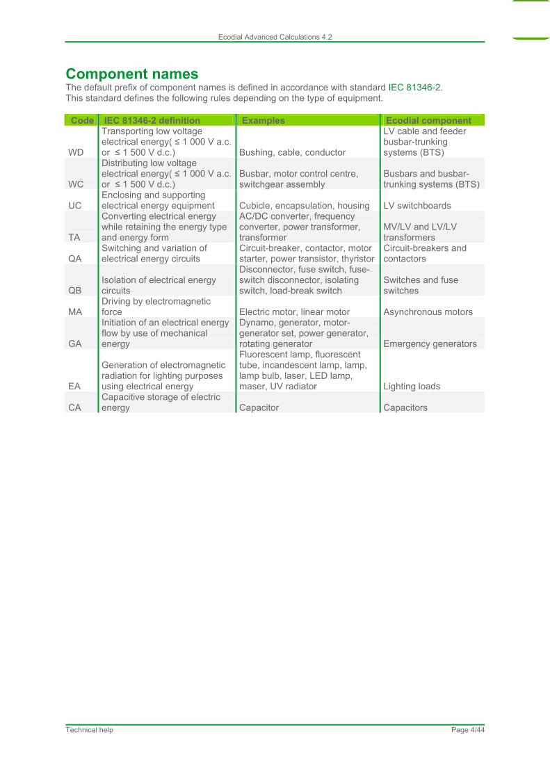
Component names The default prefix of component names is defined in accordance with standard IEC 81346-2. This standard defines the following rules depending on the type of equipment.
Code IEC 81346-2 definition Examples Ecodial component
WD
Transporting low voltage electrical energy( ≤ 1 000 V a.c. or ≤ 1 500 V d.c.) Bushing, cable, conductor
LV cable and feeder busbar-trunking systems (BTS)
WC
Distributing low voltage electrical energy( ≤ 1 000 V a.c. or ≤ 1 500 V d.c.)
Busbar, motor control centre, switchgear assembly
Busbars and busbar-trunking systems (BTS)
UC Enclosing and supporting electrical energy equipment Cubicle, encapsulation, housing LV switchboards
TA
Converting electrical energy while retaining the energy type and energy form
AC/DC converter, frequency converter, power transformer, transformer
MV/LV and LV/LV transformers
QA Switching and variation of electrical energy circuits
Circuit-breaker, contactor, motor starter, power transistor, thyristor
Circuit-breakers and contactors
QB Isolation of electrical energy circuits
Disconnector, fuse switch, fuse-switch disconnector, isolating switch, load-break switch
Switches and fuse switches
MA Driving by electromagnetic force Electric motor, linear motor Asynchronous motors
GA
Initiation of an electrical energy flow by use of mechanical energy
Dynamo, generator, motor-generator set, power generator, rotating generator Emergency generators
EA
Generation of electromagnetic radiation for lighting purposes using electrical energy
Fluorescent lamp, fluorescent tube, incandescent lamp, lamp, lamp bulb, laser, LED lamp, maser, UV radiator Lighting loads
CA Capacitive storage of electric energy Capacitor Capacitors
Technical help Page 4/44
Ecodial Advanced Calculations 4.2
Main changes following the Cenelec TR50480 report
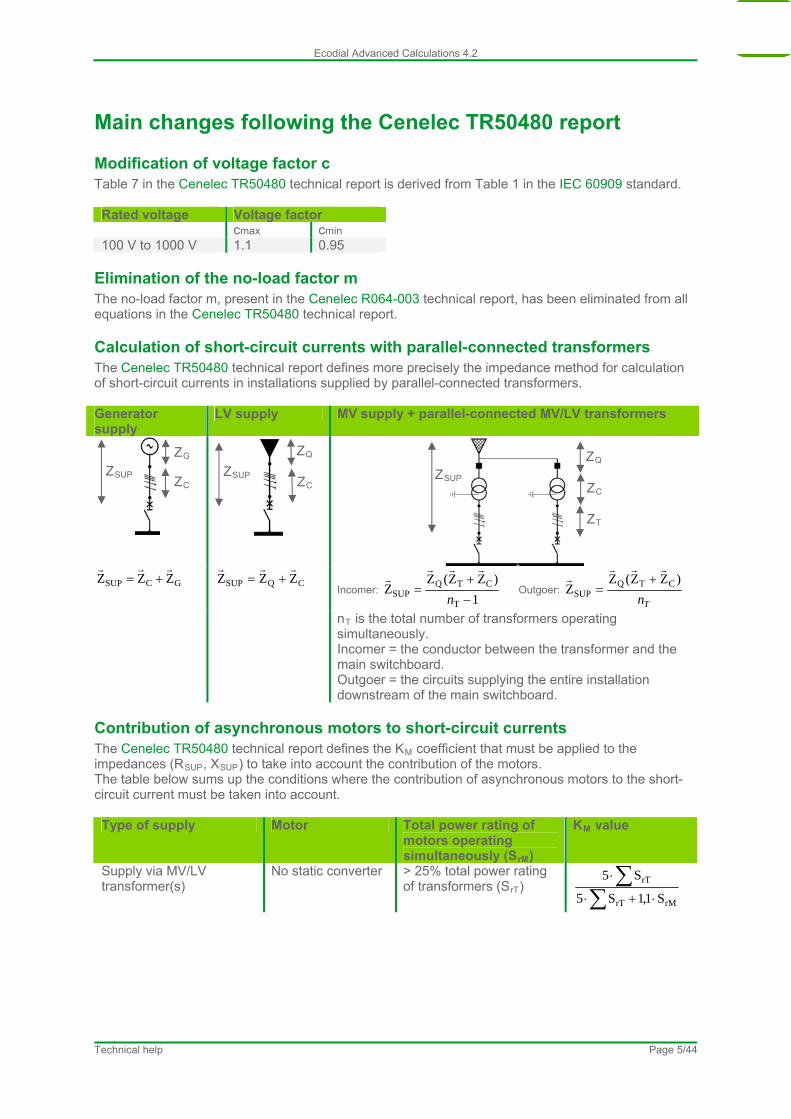
Modification of voltage factor c Table 7 in the Cenelec TR50480 technical report is derived from Table 1 in the IEC 60909 standard. Rated voltage Voltage factor cmax cmin 100 V to 1000 V 1.1 0.95
Elimination of the no-load factor m The no-load factor m, present in the Cenelec R064-003 technical report, has been eliminated from all equations in the Cenelec TR50480 technical report.
Calculation of short-circuit currents with parallel-connected transformers The Cenelec TR50480 technical report defines more precisely the impedance method for calculation of short-circuit currents in installations supplied by parallel-connected transformers. Generator supply
LV supply MV supply + parallel-connected MV/LV transformers
GCSUP ZZZ
CQSUP ZZZ
Incomer:
1
)ZZ(ZZ
T
CTQSUP
n
Outgoer: Tn
)ZZ(ZZ CTQ
SUP
nT is the total number of transformers operating simultaneously. Incomer = the conductor between the transformer and the main switchboard. Outgoer = the circuits supplying the entire installation downstream of the main switchboard.
ZC
ZQ
ZSUP ZSUP ZC
ZG
ZSUP ZC
ZT
ZQ
Contribution of asynchronous motors to short-circuit currents The Cenelec TR50480 technical report defines the KM coefficient that must be applied to the impedances (RSUP, XSUP) to take into account the contribution of the motors. The table below sums up the conditions where the contribution of asynchronous motors to the short-circuit current must be taken into account. Type of supply Motor Total power rating of
motors operating simultaneously (SrM)
KM value
Supply via MV/LV transformer(s)
No static converter > 25% total power rating of transformers (SrT)
rMrT
rT
S1,1S5
S5
Technical help Page 5/44
Ecodial Advanced Calculations 4.2
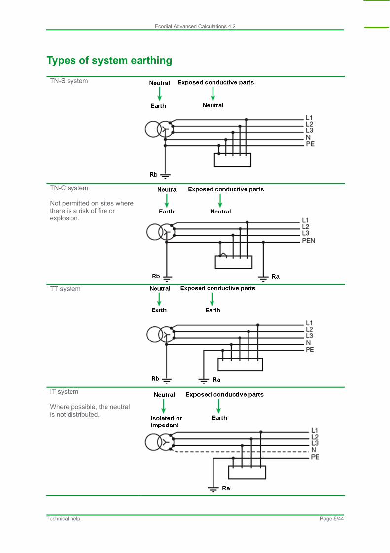
Types of system earthing TN-S system
TN-C system Not permitted on sites where there is a risk of fire or explosion.
TT system
IT system Where possible, the neutral is not distributed.
Technical help Page 6/44
Ecodial Advanced Calculations 4.2
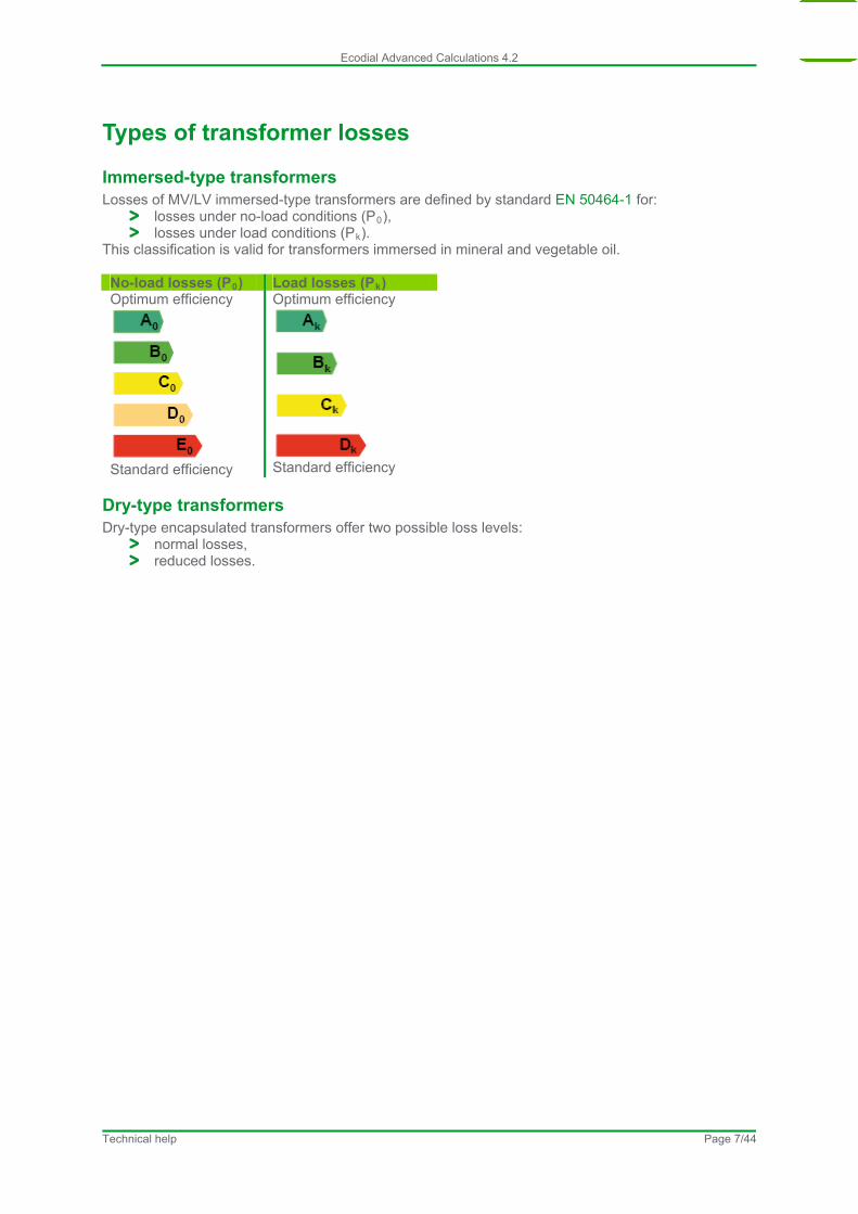
Types of transformer losses
Immersed-type transformers Losses of MV/LV immersed-type transformers are defined by standard EN 50464-1 for:
losses under no-load conditions (P0), losses under load conditions (Pk).
This classification is valid for transformers immersed in mineral and vegetable oil. No-load losses (P0) Load losses (Pk) Optimum efficiency
Standard efficiency
Optimum efficiency
Standard efficiency
Dry-type transformers Dry-type encapsulated transformers offer two possible loss levels:
normal losses, reduced losses.
Technical help Page 7/44

Ecodial Advanced Calculations 4.2
Diversity factor Ks Standard IEC 60439-1 defines the diversity-factor (Ks) values that may be used if more precise information on switchboards and busbar-trunking systems (BTS) is lacking. Ecodial uses these values by default to calculate the design currents for BTSs and busbars.
Switchboard busbars Number of outgoers Ks 1 1 2-3 0.9 4-5 0.8 6 to 9 0.7 10 and more 0.6
Distribution BTS Number of outgoers Ks 1 1 2-3 0.9 4-5 0.8 6 to 9 0.7 10 to 40 0.6 Over 40 0.5
Diversity factor and operating mode For distribution BTSs and busbars, it is possible to set a diversity factor for each type of operating mode. Simply select an operating mode and enter a value between 0 and 1 for the Ks parameter. The value becomes the default value for the current operating mode (the lock next to the parameter closes ) and Ecodial will no longer modify the value as a function of the number of outgoers. In the other operating modes, the Ks value will continue to be calculated by Ecodial, unless the value is set as indicated above.
Technical help Page 8/44
Ecodial Advanced Calculations 4.2
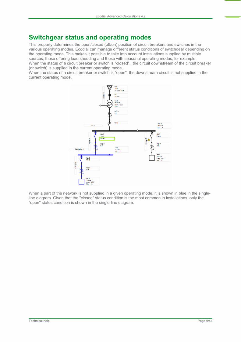
Switchgear status and operating modes This property determines the open/closed (off/on) position of circuit breakers and switches in the various operating modes. Ecodial can manage different status conditions of switchgear depending on the operating mode. This makes it possible to take into account installations supplied by multiple sources, those offering load shedding and those with seasonal operating modes, for example. When the status of a circuit breaker or switch is "closed",, the circuit downstream of the circuit breaker (or switch) is supplied in the current operating mode. When the status of a circuit breaker or switch is "open", the downstream circuit is not supplied in the current operating mode.
When a part of the network is not supplied in a given operating mode, it is shown in blue in the single-line diagram. Given that the "closed" status condition is the most common in installations, only the "open" status condition is shown in the single-line diagram.
Technical help Page 9/44
Ecodial Advanced Calculations 4.2
Discrimination of protective devices
Principle
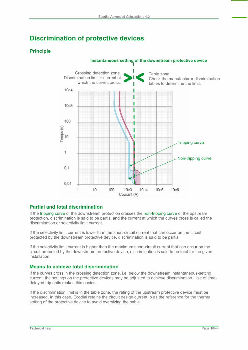
Tripping curve
Non-tripping curve
Table zone. Check the manufacturer discrimination tables to determine the limit.
Crossing detection zone. Discrimination limit = current at
which the curves cross.
Instantaneous setting of the downstream protective device
Partial and total discrimination If the tripping curve of the downstream protection crosses the non-tripping curve of the upstream protection, discrimination is said to be partial and the current at which the curves cross is called the discrimination or selectivity limit current. If the selectivity limit current is lower than the short-circuit current that can occur on the circuit protected by the downstream protective device, discrimination is said to be partial. If the selectivity limit current is higher than the maximum short-circuit current that can occur on the circuit protected by the downstream protective device, discrimination is said to be total for the given installation.
Means to achieve total discrimination If the curves cross in the crossing detection zone, i.e. below the downstream instantaneous-setting current, the settings on the protective devices may be adjusted to achieve discrimination. Use of time-delayed trip units makes this easier. If the discrimination limit is in the table zone, the rating of the upstream protective device must be increased. In this case, Ecodial retains the circuit design current Ib as the reference for the thermal setting of the protective device to avoid oversizing the cable.
Technical help Page 10/44
Ecodial Advanced Calculations 4.2
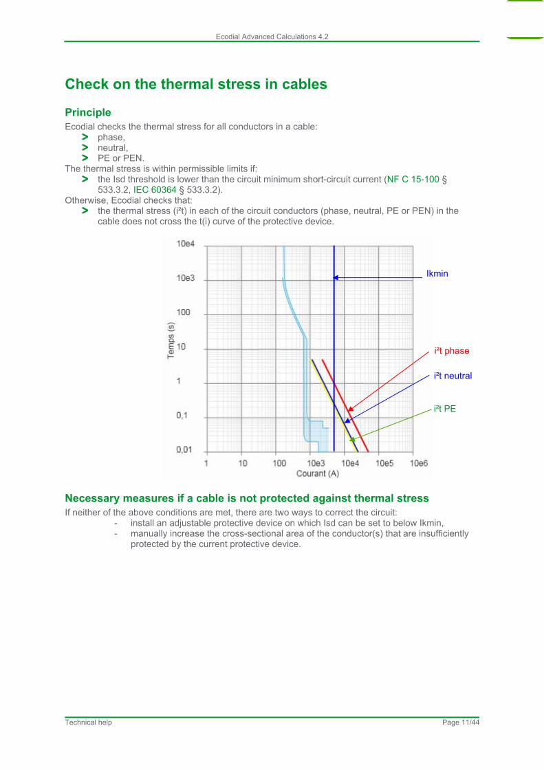
Check on the thermal stress in cables
Principle Ecodial checks the thermal stress for all conductors in a cable:
phase, neutral, PE or PEN.
The thermal stress is within permissible limits if: the Isd threshold is lower than the circuit minimum short-circuit current (NF C 15-100 §
533.3.2, IEC 60364 § 533.3.2). Otherwise, Ecodial checks that:
the thermal stress (i²t) in each of the circuit conductors (phase, neutral, PE or PEN) in the cable does not cross the t(i) curve of the protective device.
Ikmin
i²t phase
i²t PE
i²t neutral
Necessary measures if a cable is not protected against thermal stress If neither of the above conditions are met, there are two ways to correct the circuit:
- install an adjustable protective device on which Isd can be set to below Ikmin, - manually increase the cross-sectional area of the conductor(s) that are insufficiently
protected by the current protective device.
Technical help Page 11/44
Ecodial Advanced Calculations 4.2
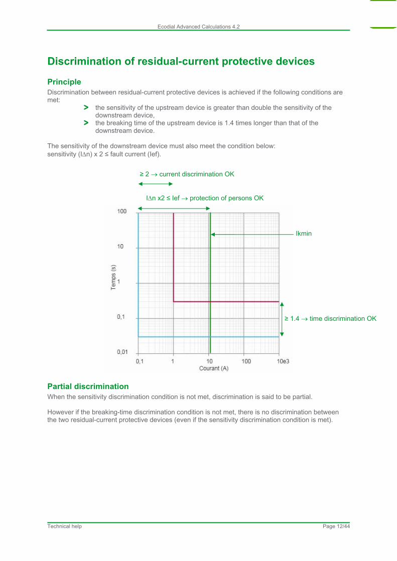
Discrimination of residual-current protective devices
Principle Discrimination between residual-current protective devices is achieved if the following conditions are met:
the sensitivity of the upstream device is greater than double the sensitivity of the downstream device,
the breaking time of the upstream device is 1.4 times longer than that of the downstream device.
The sensitivity of the downstream device must also meet the condition below: sensitivity (In) x 2 ≤ fault current (Ief).
≥ 2 current discrimination OK
In x2 ≤ Ief protection of persons OK
Ikmin
≥ 1.4 time discrimination OK
Partial discrimination When the sensitivity discrimination condition is not met, discrimination is said to be partial. However if the breaking-time discrimination condition is not met, there is no discrimination between the two residual-current protective devices (even if the sensitivity discrimination condition is met).
Technical help Page 12/44
Ecodial Advanced Calculations 4.2
Cascading
Default and individual parameter settings On the Project parameters tab, in the zone for device selection, it is possible to request that the system attempt to set up cascading for all final protection devices, i.e. those immediately upstream of the loads. It is on the final circuits that there is the greatest number of outgoers and consequently that cascading can provide the greatest benefits. In addition, there is an individual parameter for each circuit breaker in the installation, among the circuit-breaker properties, to activate or deactivate system attempts to establish cascading.
Attempts to find a cascading solution When cascading is requested for a circuit breaker, Ecodial looks for a cascading solution with the upstream circuit breaker. If Ecodial cannot find a cascading solution with the upstream circuit breaker, a warning message is displayed in the alarm window and solutions without cascading are proposed.
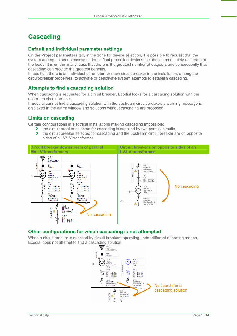
Limits on cascading Certain configurations in electrical installations making cascading impossible:
the circuit breaker selected for cascading is supplied by two parallel circuits, the circuit breaker selected for cascading and the upstream circuit breaker are on opposite
sides of a LV/LV transformer. Circuit breaker downstream of parallel MV/LV transformers
Circuit breakers on opposite sides of an LV/LV transformer
No cascading
No cascading
Other configurations for which cascading is not attempted When a circuit breaker is supplied by circuit breakers operating under different operating modes, Ecodial does not attempt to find a cascading solution.
No search for a cascading solution
Technical help Page 13/44
Ecodial Advanced Calculations 4.2
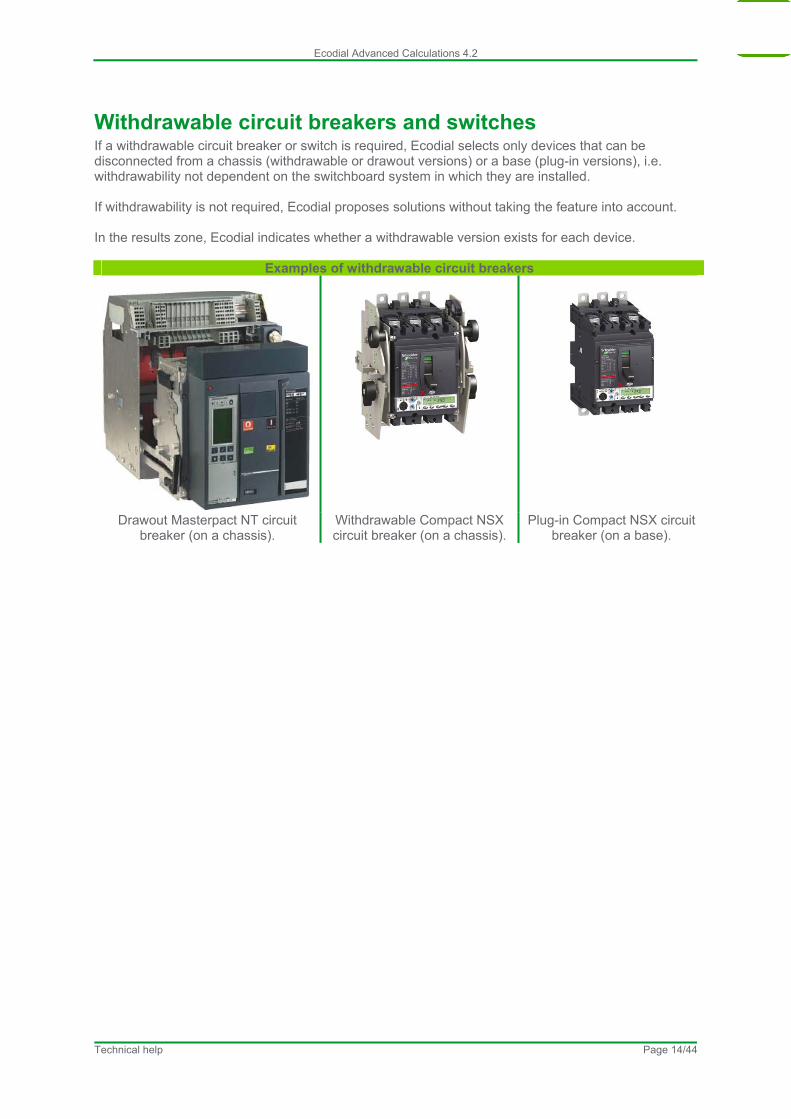
Withdrawable circuit breakers and switches If a withdrawable circuit breaker or switch is required, Ecodial selects only devices that can be disconnected from a chassis (withdrawable or drawout versions) or a base (plug-in versions), i.e. withdrawability not dependent on the switchboard system in which they are installed. If withdrawability is not required, Ecodial proposes solutions without taking the feature into account. In the results zone, Ecodial indicates whether a withdrawable version exists for each device.
Examples of withdrawable circuit breakers
Drawout Masterpact NT circuit breaker (on a chassis).
Withdrawable Compact NSX circuit breaker (on a chassis).
Plug-in Compact NSX circuit breaker (on a base).
Technical help Page 14/44
Ecodial Advanced Calculations 4.2
Electrical operating mechanisms for circuit breakers and switches If a circuit breaker or switch requires a motorised electrical operating mechanism, Ecodial selects only devices offering the option. If the option is not required, Ecodial proposes solutions without taking the option into account. In the results zone, Ecodial indicates whether the option exists for each device.
Technical help Page 15/44

Ecodial Advanced Calculations 4.2
Remote opening of switches If remote opening of a switch is required, Ecodial selects only devices offering the option. This function may be used, for example, for load shedding. If the option is not requested, Ecodial selects only devices that cannot be remotely opened. In the absence of an indication (parameter set to Any), Ecodial proposes solutions without taking the option into account. In all cases, Ecodial indicates in the results zone whether each device can be remotely opened or not.
Technical help Page 16/44

Ecodial Advanced Calculations 4.2
Visible break For certain applications, visible breaking of circuit may be required for safety reasons. On a device offering visible break, the operator can see via a transparent screen that the contacts are in fact open. For example, the Interpact INV range offers a double safety function with visible break and positive contact indication.
If visible break is required on a switch, Ecodial selects only switches offering the function. If it is not required, Ecodial selects only devices not offering the function. In the absence of an indication (parameter set to Any), Ecodial proposes solutions without taking the function into account. In all cases, Ecodial indicates for each device in the results zone whether the function is available.
Technical help Page 17/44
Ecodial Advanced Calculations 4.2
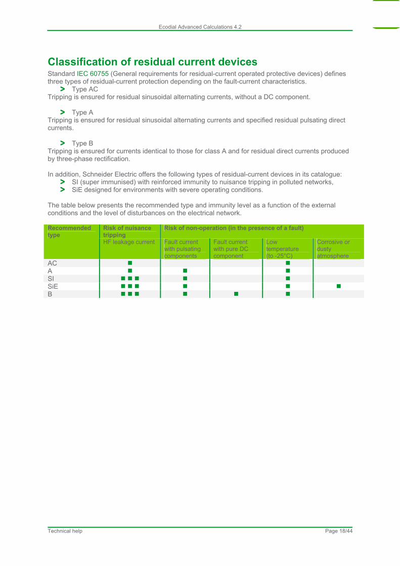
Classification of residual current devices Standard IEC 60755 (General requirements for residual-current operated protective devices) defines three types of residual-current protection depending on the fault-current characteristics.
Type AC Tripping is ensured for residual sinusoidal alternating currents, without a DC component.
Type A Tripping is ensured for residual sinusoidal alternating currents and specified residual pulsating direct currents.
Type B Tripping is ensured for currents identical to those for class A and for residual direct currents produced by three-phase rectification. In addition, Schneider Electric offers the following types of residual-current devices in its catalogue:
SI (super immunised) with reinforced immunity to nuisance tripping in polluted networks, SiE designed for environments with severe operating conditions.
The table below presents the recommended type and immunity level as a function of the external conditions and the level of disturbances on the electrical network.
Risk of nuisance tripping
Risk of non-operation (in the presence of a fault) Recommended type
HF leakage current Fault current with pulsating components
Fault current with pure DC component
Low temperature (to -25°C)
Corrosive or dusty atmosphere
AC A SI SiE B
Technical help Page 18/44
Ecodial Advanced Calculations 4.2
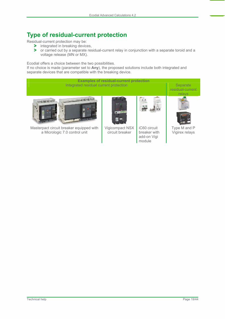
Type of residual-current protection Residual-current protection may be:
integrated in breaking devices, or carried out by a separate residual-current relay in conjunction with a separate toroid and a
voltage release (MN or MX). Ecodial offers a choice between the two possibilities. If no choice is made (parameter set to Any), the proposed solutions include both integrated and separate devices that are compatible with the breaking device.
Examples of residual-current protection Integrated residual current protection Separate
residual-current relays
Masterpact circuit breaker equipped with
a Micrologic 7.0 control unit Vigicompact NSX
circuit breaker iC60 circuit breaker with add-on Vigi module
Type M and P Vigirex relays
Technical help Page 19/44
Ecodial Advanced Calculations 4.2
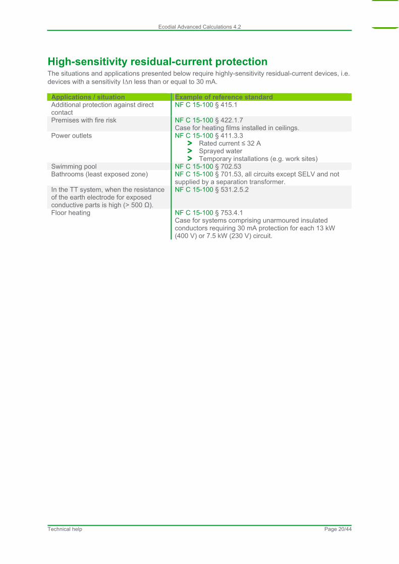
High-sensitivity residual-current protection The situations and applications presented below require highly-sensitivity residual-current devices, i.e. devices with a sensitivity In less than or equal to 30 mA. Applications / situation Example of reference standard Additional protection against direct contact
NF C 15-100 § 415.1
Premises with fire risk NF C 15-100 § 422.1.7 Case for heating films installed in ceilings.
Power outlets NF C 15-100 § 411.3.3 Rated current ≤ 32 A Sprayed water Temporary installations (e.g. work sites)
Swimming pool NF C 15-100 § 702.53 Bathrooms (least exposed zone) NF C 15-100 § 701.53, all circuits except SELV and not
supplied by a separation transformer. In the TT system, when the resistance of the earth electrode for exposed conductive parts is high (> 500 Ω).
NF C 15-100 § 531.2.5.2
Floor heating NF C 15-100 § 753.4.1 Case for systems comprising unarmoured insulated conductors requiring 30 mA protection for each 13 kW (400 V) or 7.5 kW (230 V) circuit.
Technical help Page 20/44
Ecodial Advanced Calculations 4.2
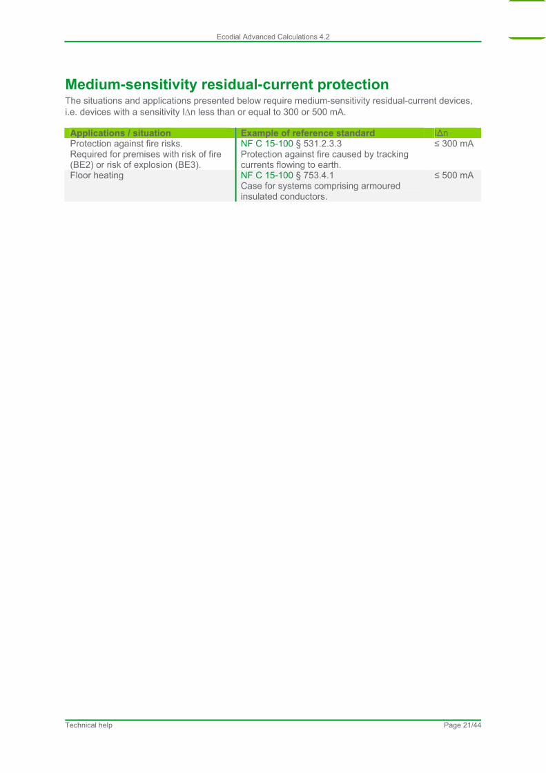
Medium-sensitivity residual-current protection The situations and applications presented below require medium-sensitivity residual-current devices, i.e. devices with a sensitivity In less than or equal to 300 or 500 mA. Applications / situation Example of reference standard IΔn Protection against fire risks. Required for premises with risk of fire (BE2) or risk of explosion (BE3).
NF C 15-100 § 531.2.3.3 Protection against fire caused by tracking currents flowing to earth.
≤ 300 mA
Floor heating NF C 15-100 § 753.4.1 Case for systems comprising armoured insulated conductors.
≤ 500 mA
Technical help Page 21/44
Ecodial Advanced Calculations 4.2
Maximum permissible voltage drop for loads
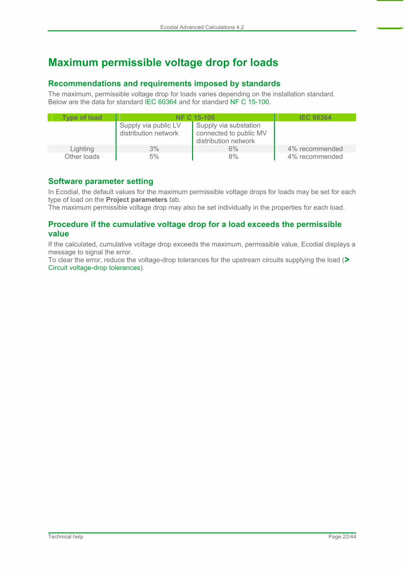
Recommendations and requirements imposed by standards The maximum, permissible voltage drop for loads varies depending on the installation standard. Below are the data for standard IEC 60364 and for standard NF C 15-100.
Type of load NF C 15-100 IEC 60364 Supply via public LV
distribution network Supply via substation connected to public MV distribution network
Lighting 3% 6% 4% recommended Other loads 5% 8% 4% recommended
Software parameter setting In Ecodial, the default values for the maximum permissible voltage drops for loads may be set for each type of load on the Project parameters tab. The maximum permissible voltage drop may also be set individually in the properties for each load.
Procedure if the cumulative voltage drop for a load exceeds the permissible value If the calculated, cumulative voltage drop exceeds the maximum, permissible value, Ecodial displays a message to signal the error. To clear the error, reduce the voltage-drop tolerances for the upstream circuits supplying the load ( Circuit voltage-drop tolerances).
Technical help Page 22/44
Ecodial Advanced Calculations 4.2
Circuit voltage-drop tolerances The default value for circuit voltage-drop tolerances can be set on the Projects parameters tab for:
cables, busbar-trunking systems (BTS).
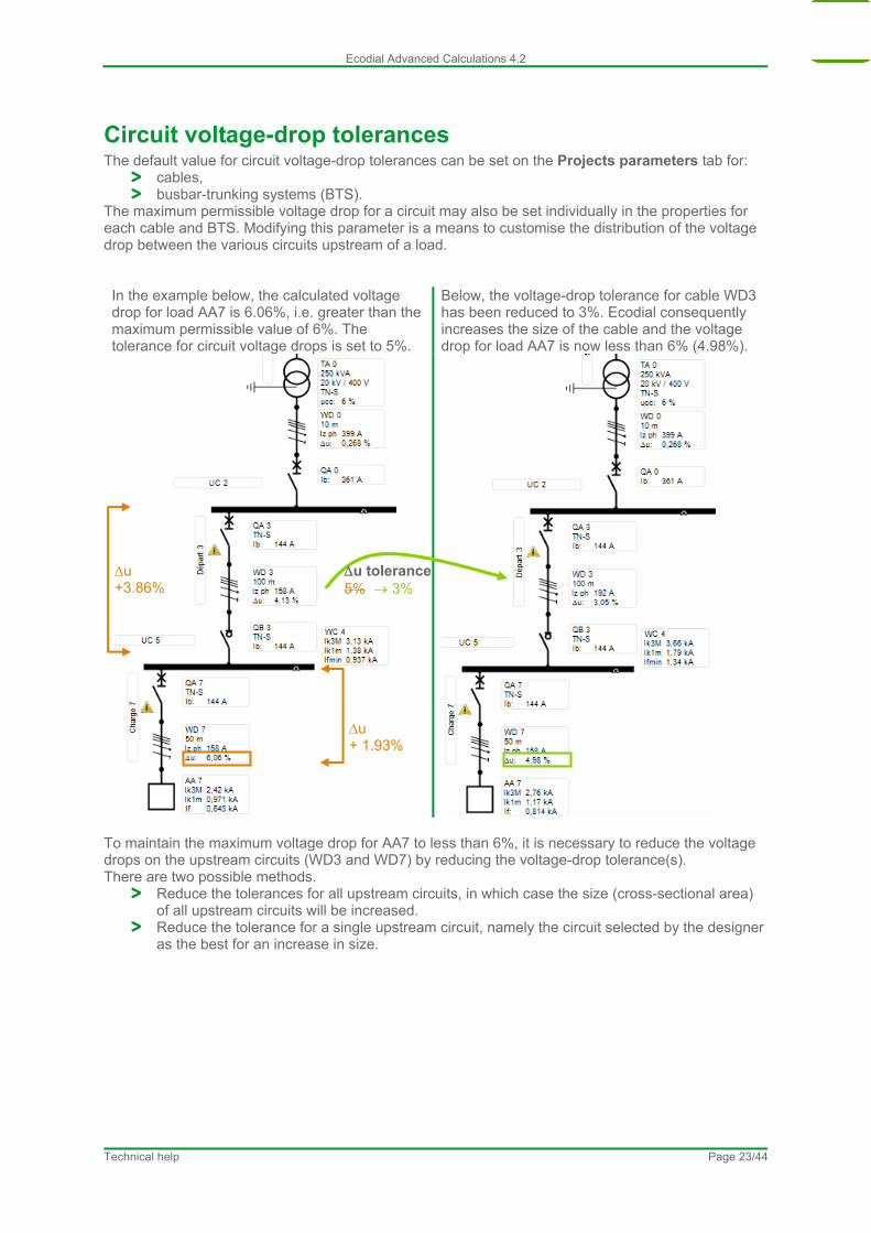
The maximum permissible voltage drop for a circuit may also be set individually in the properties for each cable and BTS. Modifying this parameter is a means to customise the distribution of the voltage drop between the various circuits upstream of a load. In the example below, the calculated voltage drop for load AA7 is 6.06%, i.e. greater than the maximum permissible value of 6%. The tolerance for circuit voltage drops is set to 5%.
Below, the voltage-drop tolerance for cable WD3 has been reduced to 3%. Ecodial consequently increases the size of the cable and the voltage drop for load AA7 is now less than 6% (4.98%).
u +3.86%
u tolerance 5% 3%
u + 1.93%
To maintain the maximum voltage drop for AA7 to less than 6%, it is necessary to reduce the voltage drops on the upstream circuits (WD3 and WD7) by reducing the voltage-drop tolerance(s). There are two possible methods.
Reduce the tolerances for all upstream circuits, in which case the size (cross-sectional area) of all upstream circuits will be increased.
Reduce the tolerance for a single upstream circuit, namely the circuit selected by the designer as the best for an increase in size.
Technical help Page 23/44

Ecodial Advanced Calculations 4.2
Cable installation method Click the Modify installation method command to modify the installation method. In the window, the information is presented in two steps:
description of the situation and of the installation system, definition of the parameters for the grouping factor that depends on the installation method.
Ecodial presents in the results zone of the window:
the installation-method number, the reference method used, a complete description of the installation method, a diagram.
Technical help Page 24/44
Ecodial Advanced Calculations 4.2
Maximum, permissible cross-sectional area This parameter may be used to limit the size (cross-sectional area) of cables and conductors. For values above the permissible limit, parallel cables are run in order to comply with the theoretical size required for the design current of the wiring system.
Technical help Page 25/44
Ecodial Advanced Calculations 4.2
Third-order harmonic distortion
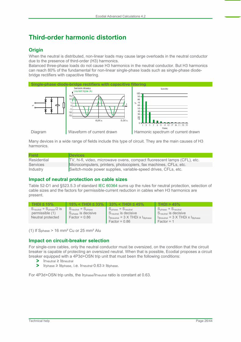
Origin When the neutral is distributed, non-linear loads may cause large overloads in the neutral conductor due to the presence of third-order (H3) harmonics. Balanced three-phase loads do not cause H3 harmonics in the neutral conductor. But H3 harmonics can reach 80% of the fundamental for non-linear single-phase loads such as single-phase diode-bridge rectifiers with capacitive filtering. Single-phase diode-bridge rectifiers with capacitive filtering
Diagram Waveform of current drawn Harmonic spectrum of current drawn Many devices in a wide range of fields include this type of circuit. They are the main causes of H3 harmonics. Field Devices Residential TV, hi-fi, video, microwave ovens, compact fluorescent lamps (CFL), etc. Services Microcomputers, printers, photocopiers, fax machines, CFLs, etc. Industry Switch-mode power supplies, variable-speed drives, CFLs, etc.
Impact of neutral protection on cable sizes Table 52-D1 and §523.5.3 of standard IEC 60364 sums up the rules for neutral protection, selection of cable sizes and the factors for permissible-current reduction in cables when H3 harmonics are present.
THDI ≤ 15% 15% < THDI ≤ 33% 33% < THDI ≤ 45% THDI > 45% Sneutral = Sphase/2 is permissible (1) Neutral protected
Sneutral = Sphase Sphase is decisive
Factor = 0.86
Sphase = Sneutral Sneutral is decisive IBneutral = 3 X THDi x IBphase Factor = 0.86
Sphase = Sneutral Sneutral is decisive IBneutral = 3 X THDi x IBphase Factor = 1
(1) If Sphase > 16 mm² Cu or 25 mm² Alu
Impact on circuit-breaker selection For single-core cables, only the neutral conductor must be oversized, on the condition that the circuit breaker is capable of protecting an oversized neutral. When that is possible, Ecodial proposes a circuit breaker equipped with a 4P3d+OSN trip unit that must been the following conditions:
Irneutral ≥ IBneutral Irphase ≥ IBphase, i.e. Irneutral·0.63 ≥ IBphase.
For 4P3d+OSN trip units, the Irphase/Irneutral ratio is constant at 0.63.
Technical help Page 26/44
Ecodial Advanced Calculations 4.2
Manual and alternate solutions The Select another product command provides access to two separate functions:
selection of alternate solutions validated by Ecodial during a calculation, manual selection of a product from the catalogue.
This command is available for the components listed below: LV cables, busbar-trunking systems (BTS), circuit breakers, switches, residual-current devices.
Alternate selection Alternate solutions may be accessed only after a calculation has been validated. If that is the case and the Select another product command is launched, the selection window automatically opens the Calculated products window. Then simply select the desired solution using the values proposed in the selection zone. The results zone is updated with the new solution. When OK is clicked, the solution is confirmed (locked), i.e. it will be used for future calculations.
Manual selection A prior, validated calculation is not required to access solutions in the catalogue. If a calculation has not yet been validated, the selection window automatically opens the Entire catalogue window. If a calculation has been validated, Ecodial opens the Calculated products selection window. Select Entire catalogue to access the entire catalogue. When a product is selected manually from the catalogue, it is "locked" for use in future calculations.
Processing of locked solutions When a solution has been locked by a user (via a manual or alternate selection), Ecodial no longer calculates the component, but it does check that the locked solution meets electrotechnical requirements. If a requirement is not met, the locked solution fails the check, the calculation is stopped and an error message is issued. To clear the problem, it is necessary to unlock the solution and restart the calculation.
Technical help Page 27/44
Ecodial Advanced Calculations 4.2
Additional derating coefficients for wiring systems This coefficient is applied in addition to the other coefficients for the installation method. The table below provides examples of typical values that should be applied when certain external conditions exist. External condition Example of recommendation (NF C 15-100) Coefficient values Premises with risk of explosion (BE3)
Permissible current values for conductors must be reduced by 15%
0.85
Significant exposure to solar radiation (AN3)
Permissible current values for conductors must be reduced by 15%
0.85
Technical help Page 28/44

Ecodial Advanced Calculations 4.2
Waiver of overload-protection requirements for safety circuits For safety reasons, an application may need to continue operation even under fault conditions, in which case overload protection should be inhibited. The inhibition function is required notably for motors used to remove smoke from public buildings. Ecodial includes a function to waiver thermal protection for circuit breakers supplying loads. In this case, two types of circuit breakers are proposed by Ecodial:
circuit breakers without thermal protection and equipped with an MA trip unit, circuit breakers equipped with a control unit enabling inhibition of thermal protection (e.g.
Micrologic 5.0). In compliance with the recommendation contained in NF C 15-100, Ecodial sizes the circuit breaker and the cable to accept 1.5 times the design current of the circuit.
Technical help Page 29/44

Ecodial Advanced Calculations 4.2
Power factor for short-circuits on LV sources By default, Ecodial proposes the values drawn from Table 11 in standard IEC 60947-2 which specifies the test conditions used to determine circuit-breaker breaking capacities.
Short-circuit current (kA) Power factor for short-circuits PFsc
Ikmax ≤ 3 0.9 3 < Ikmax ≤ 4.5 0.8 4.5 < Ikmax ≤ 6 0.7 6 < Ikmax ≤ 10 0.5 10 < Ikmax ≤ 20 0.3 20 < Ikmax ≤ 50 0.25 50 < Ikmax 0.2
Technical help Page 30/44
Ecodial Advanced Calculations 4.2
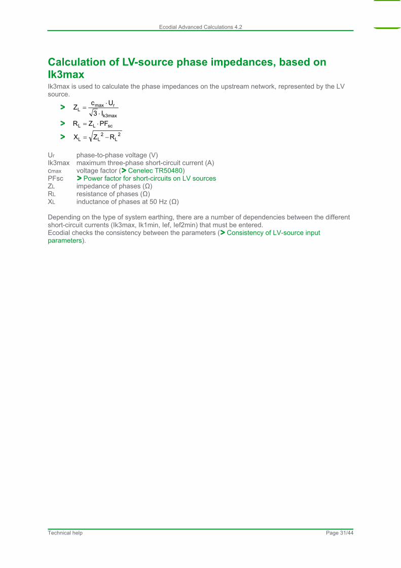
Calculation of LV-source phase impedances, based on Ik3max Ik3max is used to calculate the phase impedances on the upstream network, represented by the LV source.
k3max
rmaxL
I3
UcZ
scLL PFZR
2L
2LL RZX
Ur phase-to-phase voltage (V) Ik3max maximum three-phase short-circuit current (A) cmax voltage factor ( Cenelec TR50480) PFsc Power factor for short-circuits on LV sources ZL impedance of phases (Ω) RL resistance of phases (Ω) XL inductance of phases at 50 Hz (Ω) Depending on the type of system earthing, there are a number of dependencies between the different short-circuit currents (Ik3max, Ik1min, Ief, Ief2min) that must be entered. Ecodial checks the consistency between the parameters ( Consistency of LV-source input parameters).
Technical help Page 31/44
Ecodial Advanced Calculations 4.2
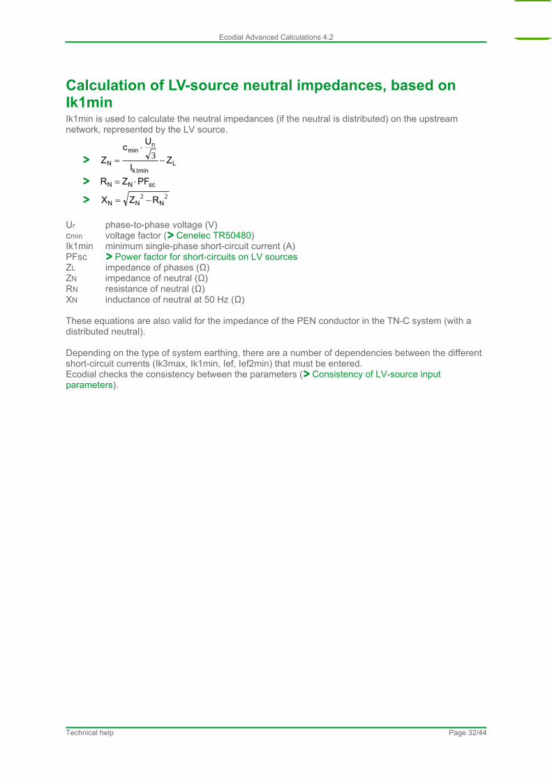
Calculation of LV-source neutral impedances, based on Ik1min Ik1min is used to calculate the neutral impedances (if the neutral is distributed) on the upstream network, represented by the LV source.
Lmink
nmin
N ZI
Uc
Z
1
3
scN N PFZR
22NNN RZX
Ur phase-to-phase voltage (V) cmin voltage factor ( Cenelec TR50480) Ik1min minimum single-phase short-circuit current (A) PFsc Power factor for short-circuits on LV sources ZL impedance of phases (Ω) ZN impedance of neutral (Ω) RN resistance of neutral (Ω) XN inductance of neutral at 50 Hz (Ω) These equations are also valid for the impedance of the PEN conductor in the TN-C system (with a distributed neutral). Depending on the type of system earthing, there are a number of dependencies between the different short-circuit currents (Ik3max, Ik1min, Ief, Ief2min) that must be entered. Ecodial checks the consistency between the parameters ( Consistency of LV-source input parameters).
Technical help Page 32/44
Ecodial Advanced Calculations 4.2
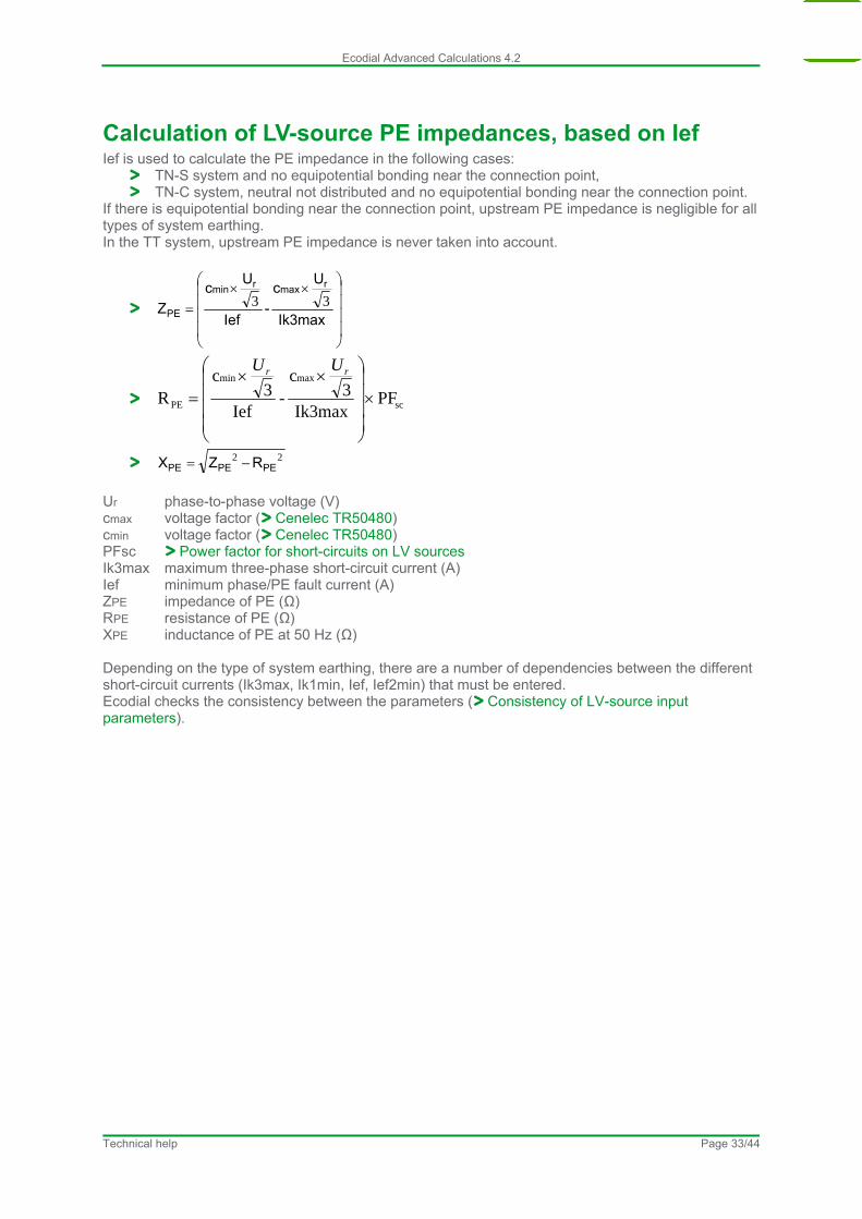
Calculation of LV-source PE impedances, based on Ief Ief is used to calculate the PE impedance in the following cases:
TN-S system and no equipotential bonding near the connection point, TN-C system, neutral not distributed and no equipotential bonding near the connection point.
If there is equipotential bonding near the connection point, upstream PE impedance is negligible for all types of system earthing. In the TT system, upstream PE impedance is never taken into account.
Ik3max
Uc
-Ief
Uc
Z
rmaxrmin
PE33
sc
maxmin
PE PFIk3max
3c
-Ief
3c
R
rr UU
22PEPEPE RZX
Ur phase-to-phase voltage (V) cmax voltage factor ( Cenelec TR50480) cmin voltage factor ( Cenelec TR50480) PFsc Power factor for short-circuits on LV sources Ik3max maximum three-phase short-circuit current (A) Ief minimum phase/PE fault current (A) ZPE impedance of PE (Ω) RPE resistance of PE (Ω) XPE inductance of PE at 50 Hz (Ω) Depending on the type of system earthing, there are a number of dependencies between the different short-circuit currents (Ik3max, Ik1min, Ief, Ief2min) that must be entered. Ecodial checks the consistency between the parameters ( Consistency of LV-source input parameters).
Technical help Page 33/44
Ecodial Advanced Calculations 4.2
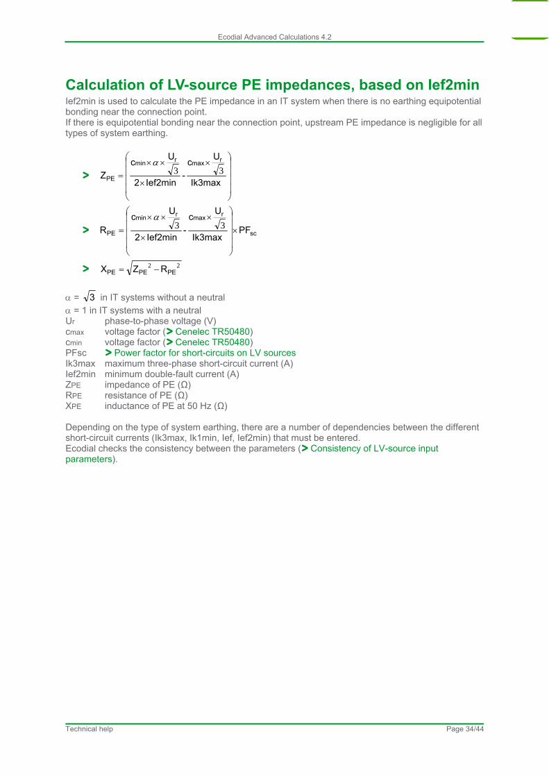
Calculation of LV-source PE impedances, based on Ief2min Ief2min is used to calculate the PE impedance in an IT system when there is no earthing equipotential bonding near the connection point. If there is equipotential bonding near the connection point, upstream PE impedance is negligible for all types of system earthing.
Ik3max
Uc
-Ief2min2
Uc
Z
rmaxrmin
PE33
sc
rmax
rmin
PE PFIk3max
Uc
-Ief2min2
Uc
R
33
22PEPEPE RZX
= 3 in IT systems without a neutral
= 1 in IT systems with a neutral Ur phase-to-phase voltage (V) cmax voltage factor ( Cenelec TR50480) cmin voltage factor ( Cenelec TR50480) PFsc Power factor for short-circuits on LV sources Ik3max maximum three-phase short-circuit current (A) Ief2min minimum double-fault current (A) ZPE impedance of PE (Ω) RPE resistance of PE (Ω) XPE inductance of PE at 50 Hz (Ω) Depending on the type of system earthing, there are a number of dependencies between the different short-circuit currents (Ik3max, Ik1min, Ief, Ief2min) that must be entered. Ecodial checks the consistency between the parameters ( Consistency of LV-source input parameters).
Technical help Page 34/44
Ecodial Advanced Calculations 4.2
Technical help Page 35/44
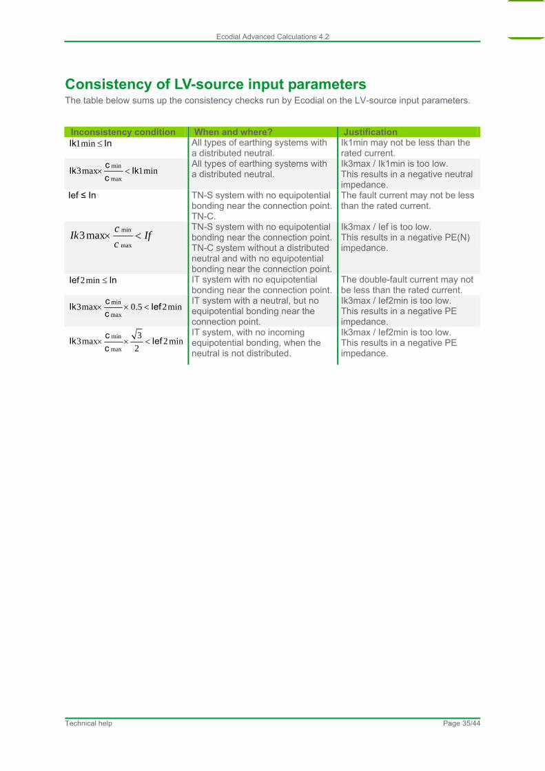
Consistency of LV-source input parameters The table below sums up the consistency checks run by Ecodial on the LV-source input parameters.
Inconsistency condition When and where? Justification InIk min1 All types of earthing systems with
a distributed neutral. Ik1min may not be less than the rated current.
min1max3max
minIk
c
cIk
All types of earthing systems with a distributed neutral.
Ik3max / Ik1min is too low. This results in a negative neutral impedance.
Ief ≤ In TN-S system with no equipotential bonding near the connection point.TN-C.
The fault current may not be less than the rated current.
Ifc
cIk
max
minmax3
TN-S system with no equipotential bonding near the connection point.TN-C system without a distributed neutral and with no equipotential bonding near the connection point.
Ik3max / Ief is too low. This results in a negative PE(N) impedance.
InIef min2 IT system with no equipotential bonding near the connection point.
The double-fault current may not be less than the rated current.
min25.0max3max
minIef
c
cIk
IT system with a neutral, but no equipotential bonding near the connection point.
Ik3max / Ief2min is too low. This results in a negative PE impedance.
min22
3max3
max
minIef
c
cIk
IT system, with no incoming equipotential bonding, when the neutral is not distributed.
Ik3max / Ief2min is too low. This results in a negative PE impedance.
Ecodial Advanced Calculations 4.2
Type of regulation of LV capacitor banks
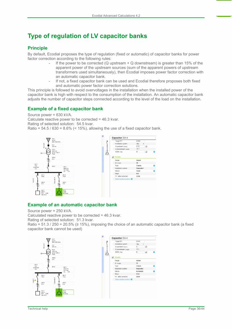
Principle By default, Ecodial proposes the type of regulation (fixed or automatic) of capacitor banks for power factor correction according to the following rules:
- If the power to be corrected (Q upstream + Q downstream) is greater than 15% of the apparent power of the upstream sources (sum of the apparent powers of upstream transformers used simultaneously), then Ecodial imposes power factor correction with an automatic capacitor bank.
- If not, a fixed capacitor bank can be used and Ecodial therefore proposes both fixed and automatic power factor correction solutions.
This principle is followed to avoid overvoltages in the installation when the installed power of the capacitor bank is high with respect to the consumption of the installation. An automatic capacitor bank adjusts the number of capacitor steps connected according to the level of the load on the installation.
Example of a fixed capacitor bank Source power = 630 kVA. Calculate reactive power to be corrected = 46.3 kvar. Rating of selected solution: 54.5 kvar. Ratio = 54.5 / 630 = 8.6% (< 15%), allowing the use of a fixed capacitor bank.
Example of an automatic capacitor bank Source power = 250 kVA. Calculated reactive power to be corrected = 46.3 kvar. Rating of selected solution: 51.3 kvar. Ratio = 51.3 / 250 = 20.5% (≥ 15%), imposing the choice of an automatic capacitor bank (a fixed capacitor bank cannot be used)
Technical help Page 36/44
Ecodial Advanced Calculations 4.2
Types of LV capacitor banks
Principle The type of capacitor bank is determined by the level of harmonic disturbances at the point of connection of the capacitor bank. The flow of harmonic currents in the installation leads to harmonic voltages across the terminals of the capacitors that can cause overcurrents at harmonic frequencies.
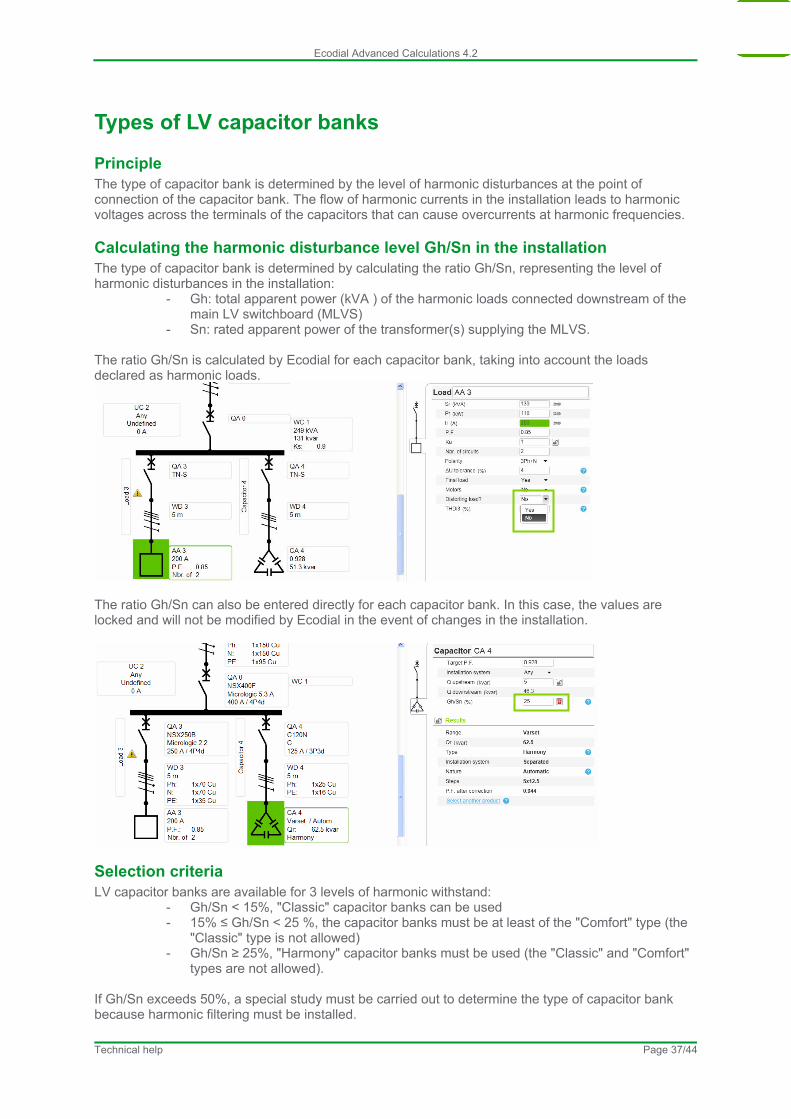
Calculating the harmonic disturbance level Gh/Sn in the installation The type of capacitor bank is determined by calculating the ratio Gh/Sn, representing the level of harmonic disturbances in the installation:
- Gh: total apparent power (kVA ) of the harmonic loads connected downstream of the main LV switchboard (MLVS)
- Sn: rated apparent power of the transformer(s) supplying the MLVS. The ratio Gh/Sn is calculated by Ecodial for each capacitor bank, taking into account the loads declared as harmonic loads.
The ratio Gh/Sn can also be entered directly for each capacitor bank. In this case, the values are locked and will not be modified by Ecodial in the event of changes in the installation.
Selection criteria LV capacitor banks are available for 3 levels of harmonic withstand:
- Gh/Sn < 15%, "Classic" capacitor banks can be used - 15% ≤ Gh/Sn < 25 %, the capacitor banks must be at least of the "Comfort" type (the
"Classic" type is not allowed) - Gh/Sn ≥ 25%, "Harmony" capacitor banks must be used (the "Classic" and "Comfort"
types are not allowed). If Gh/Sn exceeds 50%, a special study must be carried out to determine the type of capacitor bank because harmonic filtering must be installed.
Technical help Page 37/44

Ecodial Advanced Calculations 4.2
Reactive power threshold This parameter determines the reactive power threshold above which power factor correction is required. If the reactive power consumed by the installation is less than this value, installation of power factor correction capacitors is unnecessary even if the PF is less than the Target PF. The following two conditions must therefore be satisfied before Ecodial will carry out capacitor bank calculations:
- PF < Target PF - Reactive power consumed > Threshold (50 kvar by default).
Technical help Page 38/44
Ecodial Advanced Calculations 4.2
Coordination of circuit breakers and contactors
Definition Standard IEC 60947-4-1 defines two types of coordination.
Type Definition Type 1 Deterioration of the contactor and the relay is acceptable under two conditions:
- no danger to operating personnel, - no danger to any components other than the contactor and the relay
Type 2 Only minor welding of the contactor or starter contacts is permissible and the contacts must be easily separated. Following type-2 coordination tests, the switchgear and controlgear functions must be fully operational.
When the switchgear and controlgear includes both the circuit breaker and contactor functions, coordination is considered to be total.
Which type of coordination is needed? Selection of a type of coordination depends on the operating conditions encountered. The goal is to achieve the best balance between the user’s needs and the cost of the installation.
Type user’s needs / cost of the optimised installation Type 1 Qualified maintenance service,
Low cost of switchgear and controlgear, Continuity of service is not imperative or may be ensured by simply replacing the faulty motor drawer.
Type 2 Continuity of service is imperative, Limited maintenance service, Specifications stipulating type 2.
Technical help Page 39/44
Ecodial Advanced Calculations 4.2
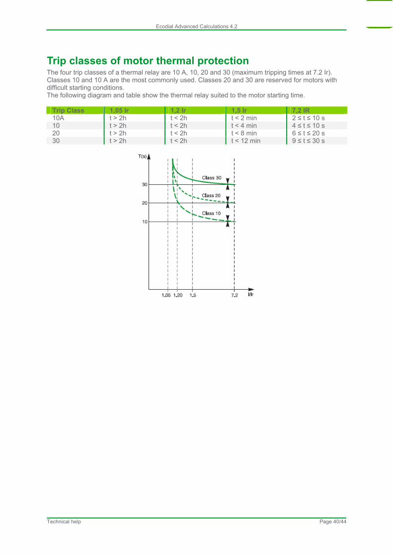
Trip classes of motor thermal protection The four trip classes of a thermal relay are 10 A, 10, 20 and 30 (maximum tripping times at 7.2 Ir). Classes 10 and 10 A are the most commonly used. Classes 20 and 30 are reserved for motors with difficult starting conditions. The following diagram and table show the thermal relay suited to the motor starting time.
Trip Class 1,05 Ir 1,2 Ir 1,5 Ir 7,2 IR 10A t > 2h t < 2h t < 2 min 2 ≤ t ≤ 10 s 10 t > 2h t < 2h t < 4 min 4 ≤ t ≤ 10 s 20 t > 2h t < 2h t < 8 min 6 ≤ t ≤ 20 s 30 t > 2h t < 2h t < 12 min 9 ≤ t ≤ 30 s
Technical help Page 40/44

Ecodial Advanced Calculations 4.2
Motor inrush currents
Principle When the motor inrush or starting current is greater than 19 Ir, device ratings are increased by 20% to satisfy optimum starting and coordination conditions.
Example I’’start/Ir ≤ 19 For an 11 kW motor with direct-on-line starting, the following protection is selected: Circuit breaker: P25 M 23 A Contactor: LC1D25
Example I’’start/Ir > 19 For an 11 kW motor with direct-on-line starting, the following protection is selected: Circuit breaker: GV2ME 32 A Contactor: LC1D32
Technical help Page 41/44
Ecodial Advanced Calculations 4.2
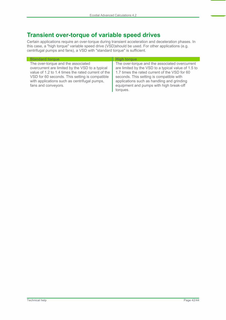
Transient over-torque of variable speed drives Certain applications require an over-torque during transient acceleration and deceleration phases. In this case, a "high torque" variable speed drive (VSD)should be used. For other applications (e.g. centrifugal pumps and fans), a VSD with "standard torque" is sufficient.
Standard torque High torque The over-torque and the associated overcurrent are limited by the VSD to a typical value of 1.2 to 1.4 times the rated current of the VSD for 60 seconds. This setting is compatible with applications such as centrifugal pumps, fans and conveyors.
The over-torque and the associated overcurrent are limited by the VSD to a typical value of 1.5 to 1.7 times the rated current of the VSD for 60 seconds. This setting is compatible with applications such as handling and grinding equipment and pumps with high break-off torques.
Technical help Page 42/44

Ecodial Advanced Calculations 4.2
Single-pole breaking capacity at phase-to-phase voltage on IT systems When a double fault occurs on an IT system, the protective devices must be able to break the double-fault current on a single pole at the phase-to-phase voltage. In IT installations, Ecodial therefore checks that the protective device satisfies the following two conditions:
- breaking capacity (Icu) greater than the maximum short-circuit current (Ik3max, Ik2max or Ik1max)
- single-pole breaking capacity at the phase-to-phase voltage greater than the double-fault current
The short-circuit currents Ik3max, Ik2max and Ik1max are calculated in compliance with Cenelec TR50480 technical report. For the double-fault current, Ecodial check that the breaking capacity at the phase-to-phase voltage is greater than:
- the current Ief calculated in compliance with Cenelec TR50480 technical report - 0.15 times the 3-phase short-circuit current at the point considered if this current is
less than or equal to 10 000 A - 0.25 times the 3-phase short-circuit current at the point considered if this current is
less than or equal to 10 000 A
Technical help Page 43/44
Ecodial Advanced Calculations 4.2
Technical help Page 44/44
Single-pole breaking capacity at phase-to-neutral voltage on TN systems Interpretation sheet F13 (dated February 2010) of standard NF C 15-100 indicates explicitly that, for TN installations, the protective devices must be able to break the double-fault current on a single pole at the phase-to-neutral voltage. No equivalent indication exists in standard IEC 60364, however all versions of Ecodial carry out this check for all protective devices and indicate the single-pole breaking capacity at the phase-to-neutral voltage when it is different than the breaking capacity Icu of the device.