EcoChill - tk-s.ru · At Thermax, not only are the products eco-friendly, but also the...
14
FOR AIRCONDITIONING AND INDUSTRIAL COOLING The eco-friendly solution .... FUEL DRIVEN ABSORPTION CHILLER - HEATERS 40 NTR - 75 NTR EcoChill TM The Latest Super Efficient Series
Transcript of EcoChill - tk-s.ru · At Thermax, not only are the products eco-friendly, but also the...
F O R A I R C O N D I T I O N I N G A N D I N D U S T R I A L C O O L I N G
T h e e c o - f r i e n d l y s o l u t i o n . . . .
F U E L D R I V E N A B S O R P T I O N C H I L L E R - H E A T E R S
ST
UD
IOM
AR
S
40 NTR - 75 NTR
EcoChill
TM
The Latest Super Efficient Series
some of our pres t i g ious ins ta l l a t i ons
tab l e o f conten t s
fuel driven absorption chiller-heaterEcoChill
TM
Conserving Energy and
Preserving the Environment.
At Thermax, not only are the
products eco-friendly, but also the
manufacturing processes. They
even conform to the Kyoto
Protocol and are in absolute
tandem with Clean Development
Mechanisms Code (CDM) which
is becoming the order of times
worldwide.
VA
PO
UR
ABSORPTION
CH
ILL
ER
S
CFC
FREE
Introduction 3
Features 4-5
Controls & Safeties 6
7
Technical Specifications 8-9
GA Drawing 11
Foundation Drawing 11
Cycle Diagrams 12
Operating Principle 13
Testing Procedure 7
Manufacturing
P & I Diagram 10
2
Name Application Country
Capital Leisure Pvt. Ltd. Entertainment India
McDonald’s Restaurant India
Sun & Sand Hotel India
Cross Word Book Stores India
Diamond Jubilee Bank Bank India
M. S. University Education India
Mahanagar Gas Ltd. Office India
Polycoat Powders Ltd. Chemicals India
ESSEX Records Office UK
Nonio Hiross Office Portugal
Mother Textile Textile Bangladesh
PRAN Agriculture Bangladesh
Epic Garment Textile Bangladesh
Pizza Hut Restaurant India
Commercial Automobiles Automobile India
Nerolac Paints Paints India

a company with engineering excellence ...
Thermax, a technology driven company has been in the core sectors of
for more than 25 years and has
defined its business as -
Electricity is scarce and expensive. It should be used
only where it is irreplaceable. Keeping this in mind, Thermax took up
the challenge of finding an alternative for traditional electrically
operated compression chillers. About a decade ago, Thermax
introduced the revolutionary concept of
for air-conditioning and process cooling requirements, in India.
Considering the growing demand for Vapour Absorption Chillers,
Thermax set up its state-of-the-art manufacturing plant in 1988, in
India at Pune which has been awarded the ISO 9001 and the ISO 14001
certificates. Needless to mention, these chillers conform to
international standards. To maintain these high standards, a team of
workers and engineers is specially trained and exposed to global work
and quality culture. With this positive and innovative attitude, Thermax
has carved a niche in the global market where competition is stiff and
performance is the only criteria.
Thermax sales and after-sales service is efficient, responsive and
responsible. Our Engineers understand customer requirements, design
the most optimal solutions and ensure quality at every stage, to achieve
customer delight.
Energy, Environment and Exports
Conserving Energy and Preserving the
Environment.
Vapour Absorption Chillers
3
C M Y K
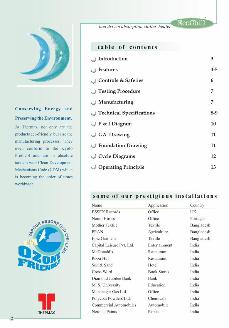
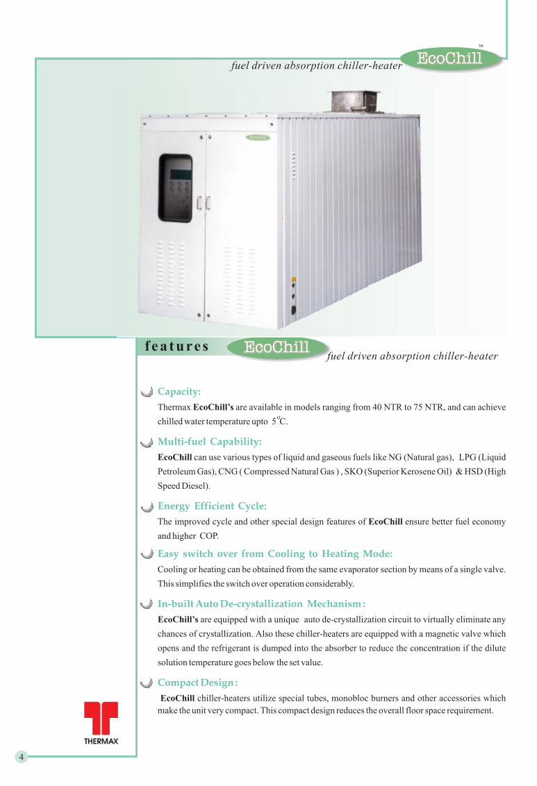
Capacity:
Multi-fuel Capability:
Energy Efficient Cycle:
Easy switch over from Cooling to Heating Mode:
In-built Auto De-crystallization Mechanism :
Compact Design :
Thermax are available in models ranging from 40 NTR to 75 NTR, and can achieve
chilled water temperature upto 5 C.
can use various types of liquid and gaseous fuels like NG (Natural gas), LPG (Liquid
Petroleum Gas), CNG ( Compressed Natural Gas ) , SKO (Superior Kerosene Oil) & HSD (High
Speed Diesel).
The improved cycle and other special design features of ensure better fuel economy
and higher COP.
Cooling or heating can be obtained from the same evaporator section by means of a single valve.
This simplifies the switch over operation considerably.
are equipped with a unique auto de-crystallization circuit to virtually eliminate any
chances of crystallization. Also these chiller-heaters are equipped with a magnetic valve which
opens and the refrigerant is dumped into the absorber to reduce the concentration if the dilute
solution temperature goes below the set value.
chiller-heaters utilize special tubes, monobloc burners and other accessories which
make the unit very compact. This compact design reduces the overall floor space requirement.
EcoChill’s
EcoChill
EcoChill
EcoChill’s
EcoChill
o
4
f ea turesfuel driven absorption chiller-heater
fuel driven absorption chiller-heaterEcoChill
TM
EcoChill
TM

opt iona l f ea tures
Simplified Generator Design :
On-line Purging :
Cross-over Piping:
PLC based Control Panel :
Corrosion Inhibitors:
Casing :
The High Temperature Generator of is provided with concentric cylinder, without any fire tubes,
thereby increasing the overall reliability of the unit and reducing the maintenance.
The factory mounted and tested purging unit consists of a palladium cell, an optional electrical motor
driven purge pump, storage tank, necessary piping and valves. Any non-condensable gas generated in the
chiller during operation, is purged continuously into the storage tank, thereby maintaining high vacuum in
the shell. The non-condensable gases collected in the storage tank can be purged periodically.
The cross-over piping from absorber to condenser is a standard feature in . It reduces the piping
work, welding, at site.
is provided with the state-of-the-art PLC based control panel, with unique display, user friendly
interface and data-logging system.
uses the new generation corrosion inhibitor, Lithium Molybdate, which is more effective than
the conventionally used Lithium Nitrate and Lithium Chromate. Lithium Nitrate can generate
Ammonium Nitrate (NH NO ) which is harmful to Copper.
chiller-heaters are factory insulated and are provided with all weather proof casing for outdoor
installation.
EcoChill
EcoChill
EcoChill
EcoChill
EcoChill
4 3
Special tube metallurgy for Evaporator / Absorber / Condenser :
The selection of tube material is done purely on the basis of the water quality available at the jobsite. Accordingly,
Thermax offers special tube material.Cupro-nickel as the
tested
-Capacity
- Fuel Consumption
- Cooling water inlet / outlet temperatures
When specified, can be provided with automatic purging system that expels non-condensables
continuously out of the storage tank or chiller depending upon the vacuum condition prevailing inside. This not
only enhances the convenience in operation but also drastically reduces / eliminates frequent human intervention
during operation.
Factory Performance Test :
After assembly, can be individually performance at the conditions specified by the customer.
During Performance Test, readings are taken for various parameters like :
- Chilled water inlet / outlet temperatures
EcoChills
EcoChills
.
Auto Purging :
fuel driven absorption chiller-heaterEcoChill
TM
5
PLC contro l s
C O N T R O L S
S A F E T I E S
Antifreeze Protection :
Crystallization Protection :
L-cut refrigerant pump.
Antifreeze thermostat.
Chilled water pump interlock.
Chilled water flow safety device.
HTG high temperature cutout.
Cooling water low temperature trip.
Alarm Cycle :
Motor Protection :
Chiller routine fault alarm.
Total shutdown alarm.
Absorbent pump thermal cutout.
Refrigerant pump overload relay.
Purge pump overload relay.
* HTG - High Temperature Generator
6
EcoChill
TM
EcoChill
TM
fuel driven absorption chiller-heater
Improved Reliability :
Elaborate Diagnostics :
Easier Operation & Maintenance :
Data Acquisition and Logging :
Holiday Schedule :
EcoChill incorporates a state-of-the-art programmable logic controller, which
incredibly enhances its flexibility and reliability. It brings along all the advantages
of a solid state control system. Elimination of rigid electro-mechanical control
components promises enhanced reliability and fail safe operation, which reduces
maintenance and ensures minimum downtime of the unit.
Control system allows the user to log parameters noted in the last one week, at a
sampling time of one hour. During a trip condition, the data is logged at a faster,
adjustable sampling time. Also a log of last six alarms with date and time stamp is
maintained.
Client can programme the units operating schedule as per his convenience so that
the it is switched on or switched off as per the programmed schedule. This
schedule can be set by the customer anytime.
Thermax Control system provides a host of diagnostic information such as
hardware related faults, trip causes, sensor errors, pump errors and data history
regarding previously occurred faults and alarms. This equips the operator with an
overview of the unit and adequate data for faster and easier troubleshooting and
routine maintenance.
Unique 2 line display, keypad and the software constitute a user-friendly operator
interface. The operator can easily control the functions, with the aid of self-
explanatory messages appropriately displayed on the screen. The status screen
provides audio-visual alarms and displays warnings about any abnormal conditions
in the unit function. This alerts the operator, specifying the abnormality, to initiate
the necessary action.
T E S T I N G P R O C E D U R E EcoChill
TM
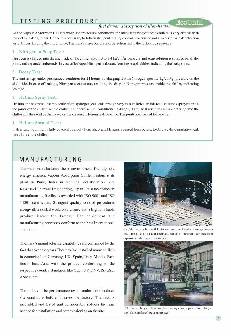
Thermax manufactures these environment friendly and
energy efficient Vapour Absorption Chiller-heaters at its
plant in Pune, India in technical collaboration with
Kawasaki Thermal Engineering, Japan. Its state-of-the-art
manufacturing facility is awarded with ISO 9001 and ISO
14001 certificates. Stringent quality control procedures
alongwith a skilled workforce ensure that a highly reliable
product leaves the factory. The equipment and
manufacturing processes conform to the best International
standards.
Thermax’s manufacturing capabilities are confirmed by the
fact that over the years Thermax has installed many chillers
in countries like Germany, UK, Spain, Italy, Middle East,
South East Asia with the product conforming to the
respective country standards like CE, TUV, DNV, ISPESL,
ASME, etc.
The units can be performance tested under the simulated
site conditions before it leaves the factory. The factory
assembled and tested unit considerably reduces the time
needed for installation and commissioning on the site.
M A N U F A C T U R I N G
CNC drilling machine with high speed and direct feed technology ensures
fine tube hole finish and accuracy, which is important for leak tight
expansion and effective heat transfer.
CNC Gas cutting machine for plate cutting ensures precision cutting of
shell plates and profile cut tube plates.
7
fuel driven absorption chiller-heater
As the Vapour Absorption Chillers work under vacuum conditions, the manufacturing of these chillers is very critical with
respect to leak tightness. Hence it is necessary to follow stringent quality control procedures and also perform leak detection
tests. Understanding the importance, Thermax carries out the leak detection test in the following sequence :
Nitrogen is charged into the shell side of the chiller upto 1.3 to 1.4 kg/cm g pressure and soap solution is sprayed on all the
joints and expanded tube ends. In case of leakage, Nitrogen leaks out, forming soap bubbles, indicating the leak points.
The unit is kept under pressurized condition for 24 hours, by charging it with Nitrogen upto 1.3 kg/cm g pressure on the
shell side. In case of leakage, Nitrogen escapes out, resulting in drop in Nitrogen pressure inside the chiller, indicating
leakage.
Helium, the next smallest molecule after Hydrogen, can leak through very minute holes. In this test Helium is sprayed on all
the joints of the chiller. As the chiller is under vacuum conditions, leakages, if any, will result in Helium entering into the
chiller and thus will be displayed on the screen of Helium leak detector. The joints are marked for repairs.
In this test, the chiller is fully covered by a polythene sheet and Helium is passed from below, to observe the cumulative leak
rate of the entire chiller.
2
2
1. Nitrogen or Soap Test :
2. Decay Test :
3. Helium Spray Test :
4. Helium Shroud Test :

C M Y K
Gas driven
T E C H N I C A L S P E C I F I C A T I O N S
8
fuel driven absorption chiller-heaterEcoChill
TM
Model Numbers UNIT EC 40 GX EC 50 GX EC 60 GX EC 75 GX
CoolingUSRT 40 50 60 75
kW 140.4 175.5 210.6 263.25
Heating kW 107.2 134.0 160.8 201.0
Chilled Water Inlet / Outlet Temp. C 12.2 / 6.7
Hot water Inlet / Outlet Temp. C 55.8 / 60
Connection Diameter mmNB 65 80
No of passes (Evaporator) nos. 6 4
Inlet / Outlet Temperature C 29.4 /
Connection Diameter mmNB 80 100
Maximum Heat Inputkcal/hr 162302 202878 244317 304748
kW 188 235 283 353
Rated Heat Input (Cooling) kW 130 163 196 244
Rated Heat Input (Heating) kW 130 163 196 244
Gas Cons
Burner Control On / Of High-Low
Absorbent Pump kW 0.75 1.1
Refrigerant Pump kW 0.1
Palladium Cell kW 0.03
Purge Pump kW 0.25
Burner Motor kW 0.25 0.75
Electric Consumption kVA 3.7 4.1 5.0
Power Supply 415 V( 10%), 50 Hz ( 5%), 3 Phase+N
Flow Rate m /hr 22.0 27.5 33.0 41.2
Friction Loss mWC 3.0 5 3.125 4.75
Flow Rate m /hr 40 50 60 75
34.8
Friction Loss mWC 6.8 11.3 7.4 11.3
No of passes (Absorber) nos. 6 4
No of passes (Condenser) nos. 2
umption Nm /hr 10.9 13.6 16.3 20.4
3
3
3
+ +
Capacity
Chilled / Hot waterCircuit
Cooling WaterCircuit
Fuel Circuit
ElectricalData
0
0
0
Gas consumption is based on Gross Calorific Value 10350 k
Heat input is based on Gross Calorific Value
Ambient condition should be between 5 to 45°C
Cooling water inlet temperature should be above 22°C
Minimum chilled water outlet temperature is 5
Fouling factor in water circuits is 0.0001 hrm /kCal
Maximum allowable pressure drop in chimney duct = 8 mm WC
Performance is according to JIS B8622
Cal/kg
°C
°C
Maximum Allowable pressure in chilled water / cooling water circuits = 5 kg/cm (g)
2
2
T E C H N I C A L S P E C I F I C A T I O N S
9
fuel driven absorption chiller-heaterEcoChill
TM
Model Numbers
Capacity
Chilled / Hot waterCircuit
Cooling WaterCircuit
Fuel Circuit
ElectricalData
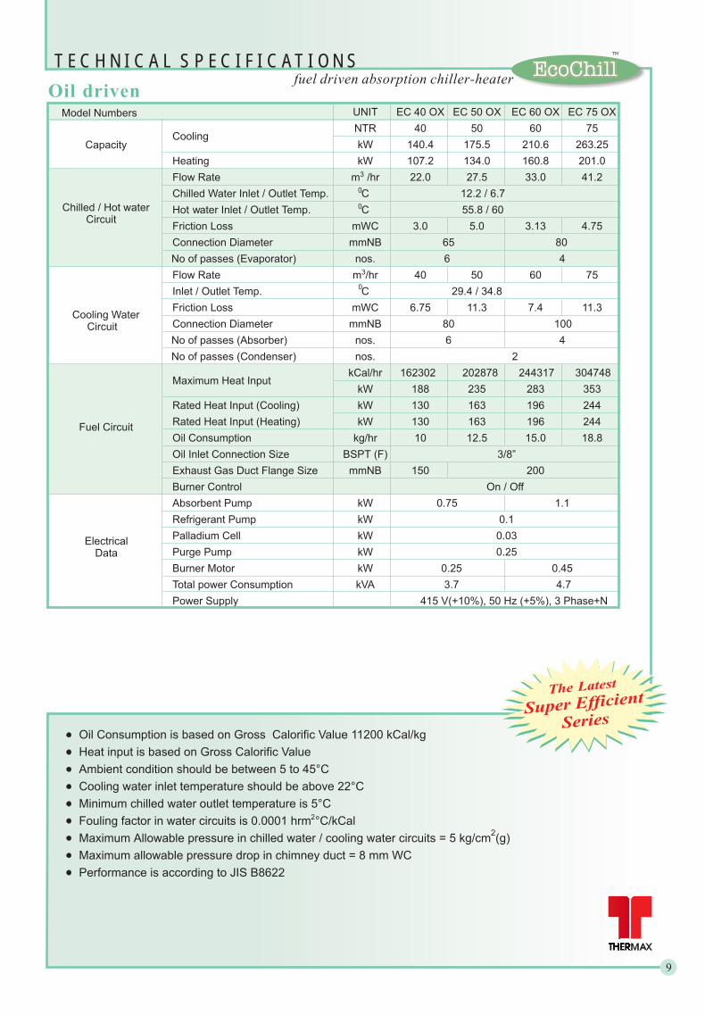
UNIT EC 40 OX EC 50 OX EC 60 OX EC 75 OX
CoolingNTR 40 50 60 75
kW 140.4 175.5 210.6 263.25
Heating kW 107.2 134.0 160.8 201.0
Chilled Water Inlet / Outlet Temp. C 12.2 / 6.7
Hot water Inlet / Outlet Temp. C 55.8 / 60
Connection Diameter mmNB 65 80
No of passes (Evaporator) nos. 6 4
Inlet / C 29.4 / 34.8
Connection Diameter mmNB 80 100
Maximum Heat InputkCal/hr 162302
kW 188 235 283 353
Rated Heat Input (Cooling) kW 130 163 196 244
Rated Heat Input (Heating) kW 130 163 196 244
Oil Cons
Burner Control On / Off
Absorbent Pump kW 0.75 1.1
Refrigerant Pump kW 0.1
Palladium Cell kW 0.03
Purge Pump kW 0.25
Burner Motor kW 0.25 0.45
Total power Consumption kVA 3.7 4.7
Power Supply 415 V(+10%), 50 Hz (+5%), 3 Phase+N
Flow Rate m /hr 22.0 27.5 33.0 41.2
Friction Loss mWC 3.0 5.0 3.13 4.75
Flow Rate m /hr 40 50 60 75
Outlet Temp.
Friction Loss mWC 6.75 11.3 7.4 11.3
No of passes (Absorber) nos. 6 4
No of passes (Condenser) nos. 2
202878 244317 304748
umption kg/hr 10 12.5 15.0 18.8
Oil Inlet Connection Size BSPT (F) 3/8”
Exhaust Gas Duct Flange Size mmNB 150 200
3
3
Oil driven
0
0
0
Oil Consumption is based on Gross Calorific Value 11200 /kg
Heat input is based on Gross Calorific Value
Ambient condition should be between 5 to 45°C
Cooling water inlet temperature should be above 22°C
Minimum chilled water outlet temperature is 5
Fouling factor in water circuits is 0.0001 hrm /kCal
Maximum allowable pressure drop in chimney duct = 8 mm WC
Performance is according to JIS B8622
kCal
°C
°C
Maximum Allowable pressure in chilled water / cooling water circuits = 5 kg/cm (g)
2
2
The Latest
Super Efficient
Series
C M Y K
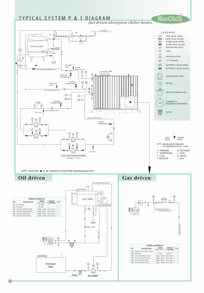
T Y P I C A L S Y S T E M P & I D I A G R A Mfuel driven absorption chiller-heater
Oil driven Gas driven
10
COOLING WATER BYPASS LINE
DOWNBLOW
COOLING TOWER
PI TI
WATER OUTLET
TO SUMP
Chemical
cleaning valve
TIPI
CHILLED WATER OUTLET
Air purge
valve
FM
CHILLED WATER INLET
TI
PI
Drain valve
COOLING WATER PUMPS
M
(1 WORKING + 1 STD BY)
M
PI
PI
Drain Valve
FM
COOLING WATER INLET
PI
PI
Chemical
cleaning valve
PI
PIM
PI
PIM
WATER
MAKE UP
COOLINGvalve
Air purge
TI
PI
cleaning valve
Chemical
cleaning valveChemical
AIR HEADER
E/P
TIC
ITSL
TE
*
1000 mmWC (max)
Gas 200 mmWC (min)
Natu
ralG
as
Supply
PI PI
GATE VALVE (OPEN)
GLOBE VALVE (OPEN)
NON RETURN VALVE
``Y'' STRAINER
GATE VALVE (CLOSE)
GLOBE VALVE (CLOSE)
GAS REGULATOR
COCK
CENTRIFUGAL PUMP
BUTTERFLY VALVE (OPEN)
BUTTERFLY VALVE (CLOSE)
PI MOTOR
AIR FILTER REGULATOR
E/PCURRENT TO
PNEUMATIC CONVERTER
L E G E N D S
FILTER
MultiBlock
SIZES
100NB
100NB
80NB
80NB
1-1/2" BSP
---
60/75SR.
N2
N6
N5
N3
N4
N1
CHILLED WATER INLET
CHILLED WATER OUTLET
COOLING WATER INLET
DESCRIPTION
COOLING WATER OUTLET
NOZZLE SCHEDULE
GAS INLET
EXHAUST GAS OUTLET DUCT
80NB
80NB
65NB
65NB
40/50QTY
BSPT `F'
BS10 TAB.`E'
NOZZLE
FL.RATING
---
1
1
1
1
1
1
BS10 TAB.`E'
BS10 TAB.`E'
BS10 TAB.`E'
TI
Isolation Valve
STORAGE
TANK
40 mesh40 meshOIL PUMPOIL PUMP
MPI
DAY TANKLSL
LSH
OIL FROM STORAGE TANK
Drain
Air Vent
Max.2.0
mts
.
LALLSL I 2
1I
PI
3/8" BSP
3/8" BSP
SIZES
CHILLED WATER INLET
COOLING WATER OUTLET
OIL RETURN
NOZZLE SCHEDULE
CHILLED WATER OUTLET
COOLING WATER INLET
OIL INLETN2
N6
N4
N5
N3
SR.
N1
DESCRIPTION
80NB
80NB
65NB
65NB
40/50 FL.RATING
NOZZLE
---
---
100NB
100NB
80NB
80NB
60/75
1
1
1
1
1
1
QTY
BS10 TAB.`E'
BS10 TAB.`E'
BS10 TAB.`E'
BS10 TAB.`E'
SCOPE
CLIENTSCOPE
THERMAX
R - RECORDER
L - LOWI - INDICATOR
M - METERF - FLOW
L - LEVELT - TEMPERATURE
P - PRESSURE
NOTE :
NOTE : Install either or scheme for Cooling Water inlet temperature control
MAXIMUM BACK PRESSURE
AT CONDENSATE OUTLET - 2mWC.
EcoChill
TM

F O U N D A T I O N D R A W I N G
FOR REFERENCE ONLY
11
T Y P I C A L G E N E R A L A R R A N G E M E N T EcoChill
TM
PLANN2
N5
N6
N4
N3
X
X
X
X
X
X
X
X
N2
X
X X
X
N1
N2
DRAIN DITCH AROUND FOUNDATION TO
ALL DIMENSIONS ARE IN MILLIMETRES.
WATERPROOF FOR EASE OF MAINTENANCE WORK.THE FLOOR SURFACE SHOULD BE MADE
ARE SUPPLIED ALONG WITH CHILLER.FOUNDATION BOLTS (WITH NUTS & WASHERS)
4)BE PROVIDED.
3)
1)
2)
EC 40 GX / OX
EC 50 GX / OX
EC 60 GX / OX
EC 75 GX / OX
MODEL A
518
490
530
550
B
1660
2060
2480
3080
NOTES
NTR 40 50 60 75
Length (L) mm 2610 2990 3370 3998
Width (W) mm 1400 1400 1400 1400
Height (H) mm 2220 2220 2220 2220
Operating Weight x 10 kg 3 3.4 3.8 4.5
Maximum Shipping Weight x 10 kg 2.8 3.2 3.6 4.2
mm 1635 2035 2435 3035
3
3
OverallDimensions
Weight
Capacity
Clearance for Tube Removal
Note: Gas driven and Oil driven chillers have same dimensions
fuel driven absorption chiller-heater1
51
5
20
47
13
70
16
70
75
75
M
10
0
75
20A
FOUNDATION ARRANGEMENT
CHILLER BASE
260
CHILLER CASING OUTLINE
PLAN
80
180
75
M16 NUTWASHER 40x40x6
ANCHOR BOLTS
4 x M16
CHILLER FRAME OUTLINE
M
FOUNDATION POCKET
212x390x250 DEPTH
B 110
11
76
50
SECTION `M-M'
75
17
5
160230
FFL
260
FOUNDATION POCKET
212x390x250 DEPTH
N
VIEW FROM `N'
130130
62
50
fuel driven absorption chiller-heater
12
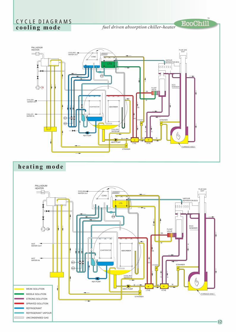
C Y C L E D I A G R A M Scoo l ing mode
hea t ing mode
EcoChill
TM
COOLING
WATER OUT
W
ABSORBEREVAPORATOR
FLOATVALVE
SEPARATION BOX
S
SS
W
SS
SS
SS
W
W
W W
LTHE HTHE
WW
ABSO.PUMP
LTG
COND
REF.PUMP
ECO-
NOMISER
STRAINER
COOLINGWATER IN
STRAINER
VAPOUR
SV2
SV1
DT8
STRAINER
M
HEATER
PALLADIUM
HOTWATER OUT
HOTWATER IN
WEAK SOLUTION
STRONG SOLUTION
SPRAYED SOLUTION
REFRIGERANT
UNCONDENSED GAS
REFRIGERANT VAPOUR
MIDDLE SOLUTION
W
FURNACE ASSLY.
FURNACE ASSLY.
ABSORBEREVAPORATOR
FLOATVALVE
SEPARATION BOX
FLUE GASEXIT
FLUE GASEXIT
SS
M
SS
SS
SS
LTHE HTHE
WW
ABSO.PUMP
LTG
COND
REF.PUMP
ECO-
NOMISER
COOLING
WATER IN
STRAINER
STRAINER
VAPOUR
M
SV2
SV1
DT8
STRAINER
HEATER
PALLADIUM
CHILLED
WATER OUT
COOLING
WATER OUT
CHILLED
WATER IN
W W
fuel driven absorption chiller-heater
Absorption process
Cooling water
LiBr solutionConcentrated
Water (refrigerant) Closed vessel
VacuumChilled water
Water circulatingheat exchangertubes
ConcentratedLiBr solution
Water (refrigerant)
Refrigerant vapour
Drivingheat source
Diluted solution
Absorption pump
Chilled water
Absorber
Cooling water
Concentratedsolution
Liquidrefrigerant
Refrigerant vapourGeneratorCondenser
Absorbent Pump
Driving heatsource
Coolingwater
Coolingwater
AbsorbentPump
Chilled water
CONDENSER GENERATOR
EVAPORATOR ABSORBER
5
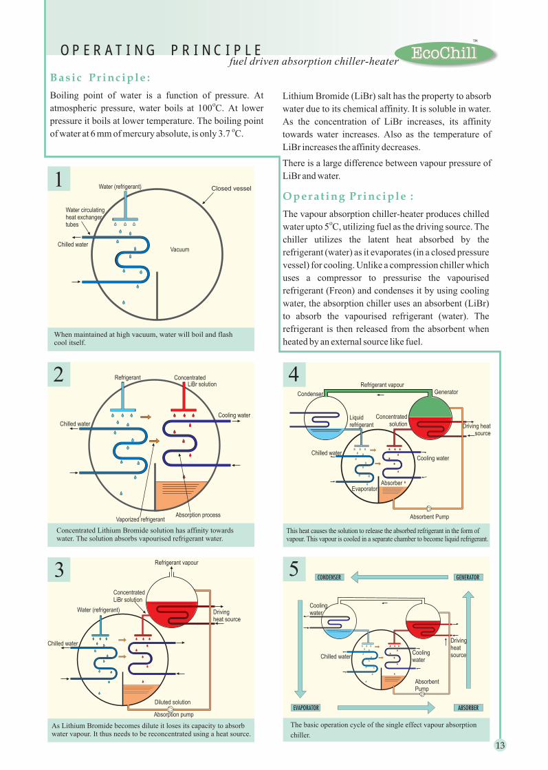
O P E R A T I N G P R I N C I P L E
Vaporized refrigerant
Refrigerant
Chilled water
Chilled water
Evaporator
4
1
2
3
Drivingheatsource
When maintained at high vacuum, water will boil and flashcool itself.
Concentrated Lithium Bromide solution has affinity towardswater. The solution absorbs vapourised refrigerant water.
As Lithium Bromide becomes dilute it loses its capacity to absorbwater vapour. It thus needs to be reconcentrated using a heat source.
The basic operation cycle of the single effect vapour absorption
chiller.
This heat causes the solution to release the absorbed refrigerant in the form ofvapour. This vapour is cooled in a separate chamber to become liquid refrigerant.
Opera t ing Pr inc iple :
The vapour absorption chiller-heater produces chilled
water upto 5 C, utilizing fuel as the driving source. The
chiller utilizes the latent heat absorbed by the
refrigerant (water) as it evaporates (in a closed pressure
vessel) for cooling. Unlike a compression chiller which
uses a compressor to pressurise the vapourised
refrigerant (Freon) and condenses it by using cooling
water, the absorption chiller uses an absorbent (LiBr)
to absorb the vapourised refrigerant (water). The
refrigerant is then released from the absorbent when
heated by an external source like fuel.
o
Basic Pr inc iple :
Boiling point of water is a function of pressure. At
atmospheric pressure, water boils at 100 C. At lower
pressure it boils at lower temperature. The boiling point
of water at 6 mm of mercury absolute, is only 3.7 C.
o
o
Lithium Bromide (LiBr) salt has the property to absorb
water due to its chemical affinity. It is soluble in water.
As the concentration of LiBr increases, its affinity
towards water increases. Also as the temperature of
LiBr increases the affinity decreases.
There is a large difference between vapour pressure of
LiBr and water.
EcoChill
TM
13

In view of our constant endeavour to improve the quality of products,we reserve the rights to alter or change design specifications and contents ofthis literature without prior notice and without incurring any obligations. Visit us at : www.thermaxindia.com/acd
Distributor / Agent
THERMAX LTD.ABSORPTION COOLING DIVISION
ACD/EcoChill/08/01
Thermax Inc.
Thermax Europe Ltd. :
U.K.
Thermax Rus Ltd. :Russia
Thermax Ltd. :Saudi Arabia
Thermax Ltd. :Kenya
Thermax Ltd. :
Nigeria
Thermax Ltd. :
Thermax Ltd. :
Indonesia
Thermax Ltd. :Bangladesh
Thermax Ltd. :Sri Lanka
40440 Grand River Avenue, Novi Michigan 48375, U.S.A.Tel : 00-1-248-426 0428 / 474 3050 Fax : 00-1-248-474 5790Email : [email protected]
Suite 7A, Britannia House, Leagrave Road, Luton, Bedfordshire,LU3 1RJ,Tel : 00-44-1582-727756 Fax : 00-44-1582-731538Email : [email protected]
Ulitsa Vavilova, House 69/75, Office 915, Moscow 117846,Tel : 00-7095-9350490-92 Fax : 00-7095-1347410Email : [email protected]
C/o. CIDC - Masdar, PO Box 20753, Al Khobar 31952,Tel : 00-966-3-891 9897 / 9594 / Fax No : 00-966-3-8914388 / 8911656Email : [email protected]
C/o. Spenomatic Kenya Ltd.,Post Box 39935, Nairobi,Tel : 00-254-2-803122/860264 / Fax : 00-254-2-444360Email : [email protected]
C/o. Multichem Industries Ltd., Plot D2, Israel Adebajo Close,Off Ladipo Oluwole Avenue, PO Box 5671, Ikeja, Lagos,Tel : 00-234-1-4924019 / 4936162 / Fax No : 00-234-1-4923998 / 2693746Email : [email protected]
Block B-22/3, Menara Bangsar, Jalan Maarof,
PT Comexindo Persada, Bidakara Bldg. 6 floor,Jl. Jendral Gatot Subroto KAV 71-73, Pancoran, Jakarta 12870,
35, New Eskaton Road, Sufia House, Dhaka,
C/o. Lalan Engg. Ltd. 344, Grandpass Road, Colombo-14,
Thermax Ltd. : U.A.E.
Malaysia
PO Box 17156 Jebel Ali, Dubai,Tel : 00-971-4-8816481 Fax : 00-971-4-8816039Email : [email protected]
Bukit Bandaraya, 59100 Kuala Lumpur,Tel : 00-60-3-2534775 Fax : 00-60-3-2544775Email : [email protected]
Tel : 00-62-21-83793259 / Fax : 00-62-21-83793258Email : [email protected]
Tel : 011-808001, 011-867393 / Fax No : 00-880-2-832963Email : [email protected]
Tel : 00-941-325997 /329566 / Fax No : 00-941-447060Email : [email protected]
th
Thermax world-wide network
REGISTERED OFFICE / WORKSD-13 MIDC Industrial Area,Chinchwad, Pune 411 019. INDIATel : 00-91-20- 7475941-49 / 7470436Fax : 00-91-20- 7475907
ST
UD
IOM
AR
S