Eclipse Gearbox
18
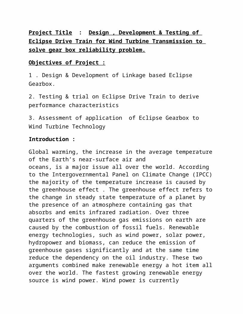
Project Title : Design , Development & Testing of Eclipse Drive Train for Wind Turbine Transmission to solve gear box reliability problem. Objectives of Project : 1 . Design & Development of Linkage based Eclipse Gearbox. 2. Testing & trial on Eclipse Drive Train to derive performance characteristics 3. Assessment of application of Eclipse Gearbox to Wind Turbine Technology Introduction : Global warming, the increase in the average temperature of the Earth’s near-surface air and oceans, is a major issue all over the world. According to the Intergovernmental Panel on Climate Change (IPCC) the majority of the temperature increase is caused by the greenhouse effect . The greenhouse effect refers to the change in steady state temperature of a planet by the presence of an atmosphere containing gas that absorbs and emits infrared radiation. Over three quarters of the greenhouse gas emissions on earth are caused by the combustion of fossil fuels. Renewable energy technologies, such as wind power, solar power, hydropower and biomass, can reduce the emission of greenhouse gases significantly and at the same time reduce the dependency on the oil industry. These two arguments combined make renewable energy a hot item all over the world. The fastest growing renewable energy source is wind power. Wind power is currently
-
Upload
dineshvhaval -
Category
Documents
-
view
39 -
download
1
description
xz
Transcript of Eclipse Gearbox
Project Title : Design , Development & Testing of Eclipse Drive Train for Wind Turbine Transmission to solve gear box reliability problem.
Objectives of Project :
1 . Design & Development of Linkage based Eclipse Gearbox.
2. Testing & trial on Eclipse Drive Train to derive performance characteristics
3. Assessment of application of Eclipse Gearbox to Wind Turbine Technology
Introduction :
Global warming, the increase in the average temperature of the Earth’s near-surface air andoceans, is a major issue all over the world. According to the Intergovernmental Panel on Climate Change (IPCC) the majority of the temperature increase is caused by the greenhouse effect . The greenhouse effect refers to the change in steady state temperature of a planet by the presence of an atmosphere containing gas that absorbs and emits infrared radiation. Over three quarters of the greenhouse gas emissions on earth are caused by the combustion of fossil fuels. Renewable energy technologies, such as wind power, solar power, hydropower and biomass, can reduce the emission of greenhouse gases significantly and at the same time reduce the dependency on the oil industry. These two arguments combined make renewable energy a hot item all over the world. The fastest growing renewable energy source is wind power. Wind power is currently responsible for about 1:5% of the world’s electricity use [2]. Because of this high interest in wind energy, it becomes more and more important to increase the efficiency of wind energy conversion systems (WECS), also called wind turbines.
A wind turbine extracts kinetic energy from the wind and converts this into mechanical energy. This mechanical energy is then converted to electrical energy by means of a generator. A wind turbine extracts the maximum amount of energy from the
wind when operating at an optimal rotor speed, which depends on the wind speed. Because the wind speed is variable by nature, the optimal rotor speed also varies. Earlier research has shown that variable speed operation of the rotor results in a higher energy production compared to a system operating at one constant speed. Next to an increase in energy production, variable speed operation enables a reduction in dynamic loads acting on the mechanical components [3, 4, 5, 6]. However, a problem arises when the speed of the rotor varies while the wind turbine must deliver AC power with a fixed phase and frequency to the electrical grid. To match the grid requirements, current variable speed wind turbines incorporate expensive power electronics to convert the variable frequency power to a constant frequency. The power electronics have a limited efficiency and they can introduce harmonic distortion of the AC current in the electrical grid, reducing the quality of the produced power. Next to these disadvantages, power electronics are one of the main sources of failure in wind turbines. They account for about 25% of turbine failures and, unlike mechanical failures, they are not predictable and therefore increase maintenance costs. At the moment, a number of wind turbines using a different technology to obtain the variable speed are available on the market. These technologies incorporate some kind of variable transmission in the drive train to control the rotor speed.
WIND TURBINES : The technology of extracting energy from the wind is an old technology. The first wind mills date back more than 2000 years and were for example used as a water pump. Over the years, especially around the 17th century, more applications have been developed and wind mills became an important feature in the industrialization.Nowadays, wind mills are better known as wind turbines and they are not used for milling grain, sawing wood or pumping water, but they are used to generate electricity. This so-called ’green’ electricity has evolved enormously over the past few decades. The high prices and coming shortage of oil, together with the global warming caused by the emission of carbon dioxide, are the main reasons for the interest in sustainable
energy. Since wind is a natural resource, the technology is sustainable and at the same time the emissions during operation are close to zero. These are all characteristics that make the wind energy industry so interesting. The energy payback time of a wind turbine is about 3¡6 months, The depending on the availability of wind at the turbinelocation.
Problem definition :Wind energy conversion system
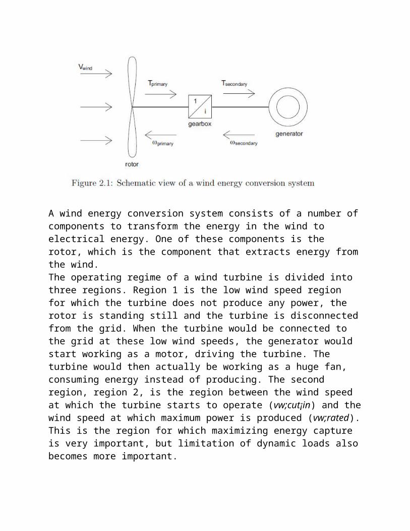
The complete system required to convert the energy in the wind to electricity is called a wind energy conversion system (WECS). Such a system consists of a rotor to capture the energy in the wind, a gearbox configuration to speed up the rotational speed of the shaft and a generator to convert the mechanical energy into electrical energy. A schematic view of a WECS is shown in Figure 2.1. The efficiency of the total system is not only determined by the efficiencies of the gearbox and generator, but also by the amount of energy that can be extracted from the wind.
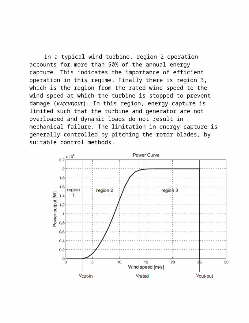
A wind energy conversion system consists of a number of components to transform the energy in the wind to electrical energy. One of these components is the rotor, which is the component that extracts energy from the wind.The operating regime of a wind turbine is divided into three regions. Region 1 is the low wind speed region for which the turbine does not produce any power, the rotor is standing still and the turbine is disconnected from the grid. When the turbine would be connected to the grid at these low wind speeds, the generator would start working as a motor, driving the turbine. The turbine would then actually be working as a huge fan, consuming energy instead of producing. The second region, region 2, is the region between the wind speed at which the turbine starts to operate (vw;cut¡in) and the wind speed at which maximum power is produced (vw;rated). This is the region for which maximizing energy capture is very important, but limitation of dynamic loads also becomes more important.
In a typical wind turbine, region 2 operation accounts for more than 50% of the annual energy capture. This indicates the importance of efficient operation in this regime. Finally there is region 3, which is the region from the rated wind speed to the
wind speed at which the turbine is stopped to prevent damage (vw;cut¡out). In this region, energy capture is limited such that the turbine and generator are not overloaded and dynamic loads do not result in mechanical failure. The limitation in energy capture is generally controlled by pitching the rotor blades, by suitable control methods.
Blade pitch control is used to control the aerodynamic power captured from the wind. By pitching the rotor blades along their longitudinal axis, the aerodynamic efficiency of the rotor is changed. A disadvantage of using blade pitching below rated speed is that less energy is extracted from the wind, decreasing the efficiency.
EXISTING SOLUTION :
Power ElectronicsVariable speed operation of the generator results in the
production of current with a variable frequency.The frequency of the produced current is determined by the electrical angular speed of the generator. For the electrical grid to remain stable, the frequency and phase of all power generating units must remain synchronous within narrow limits. When the frequency of the generator varies too much, in the order of 2 Hz, circuit breakers cause the generator to disconnect from the system, preventing damage to the grid. However, small deviations in the generator frequency canindicate instability in the grid
Power electronics is a technology that is developing rapidly. Higher current and voltage ratings are available, efficiency increases and costs decrease. Therefore, power converters are widely used in the wind turbine industry to improve the performance of wind turbines. However, there are also a number of disadvantages of using power electronics.Disadvantages of Power Electronics
The biggest disadvantage of power electronics is reliability. Mechanical components show wear & tear and therefore any failures in these components can be predicted, maintenance can be scheduled before failure occurs. Unfortunately power electronics do not show signs of degrading, therefore failures cannot be predicted and these sudden failures are very expensive to repair. Together with high failure costs, power electronics tend to fail quite rapidly because they are very sensitive to voltage spikes .In the wind energy industry about25% of all failures is due to the power electronics.
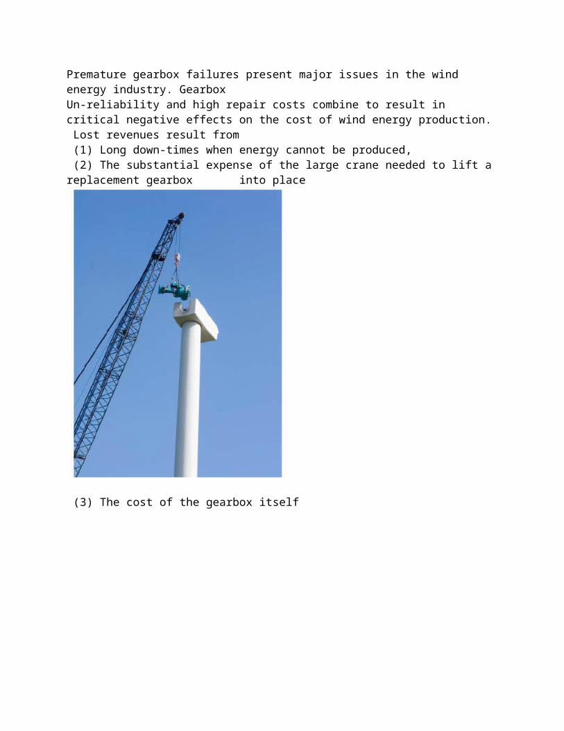
Need for project :Premature gearbox failures present major issues in the wind energy industry. GearboxUn-reliability and high repair costs combine to result in critical negative effects on the cost of wind energy production. Lost revenues result from (1) Long down-times when energy cannot be produced, (2) The substantial expense of the large crane needed to lift a replacement gearbox into place
(3) The cost of the gearbox itself

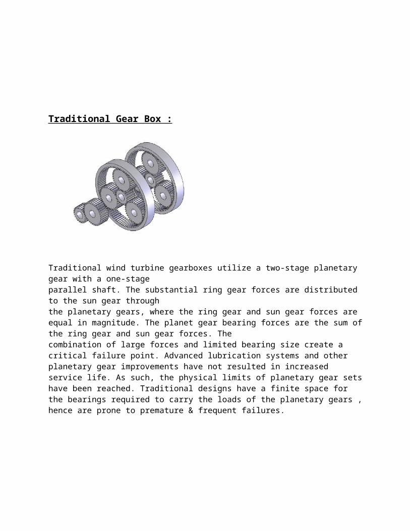
Traditional Gear Box :
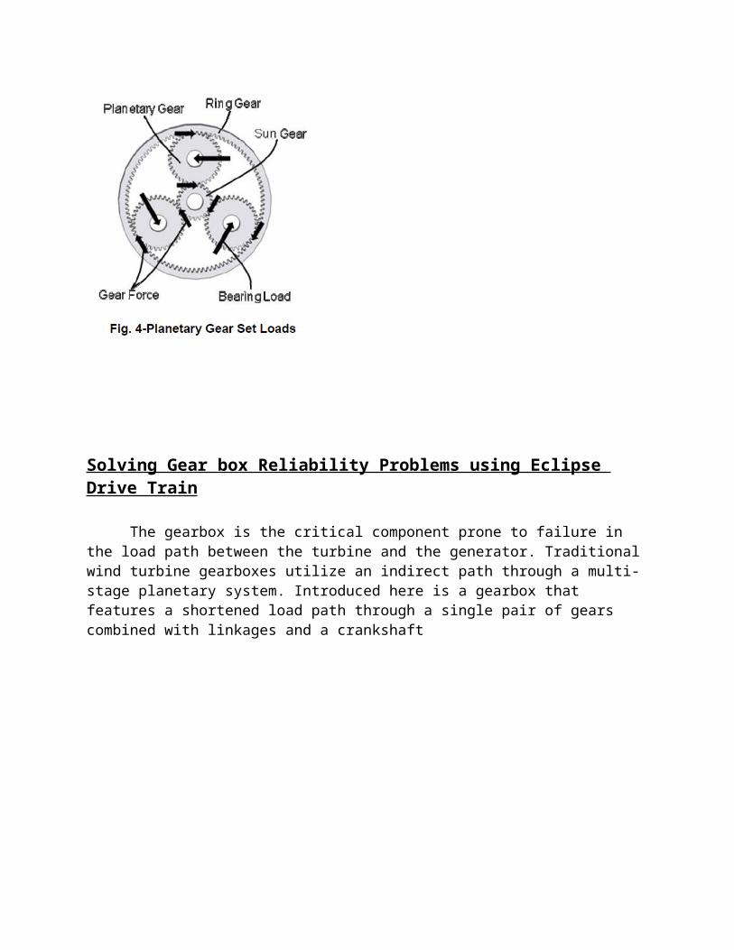
Traditional wind turbine gearboxes utilize a two-stage planetary gear with a one-stageparallel shaft. The substantial ring gear forces are distributed to the sun gear throughthe planetary gears, where the ring gear and sun gear forces are equal in magnitude. The planet gear bearing forces are the sum of the ring gear and sun gear forces. Thecombination of large forces and limited bearing size create a critical failure point. Advanced lubrication systems and other planetary gear improvements have not resulted in increased service life. As such, the physical limits of planetary gear sets have been reached. Traditional designs have a finite space for the bearings required to carry the loads of the planetary gears , hence are prone to premature & frequent failures.
Solving Gear box Reliability Problems using Eclipse Drive Train
The gearbox is the critical component prone to failure in the load path between the turbine and the generator. Traditional wind turbine gearboxes utilize an indirect path through a multi-stage planetary system. Introduced here is a gearbox that features a shortened load path through a single pair of gears combined with linkages and a crankshaft
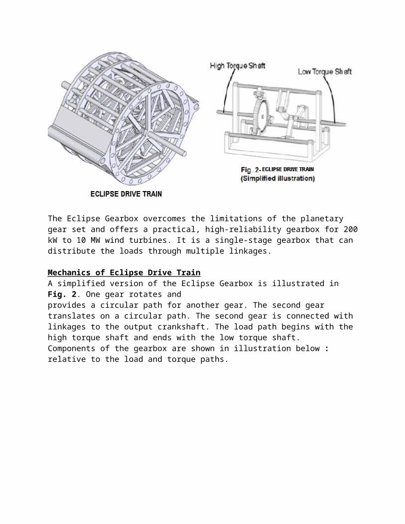
The Eclipse Gearbox overcomes the limitations of the planetary gear set and offers a practical, high-reliability gearbox for 200 kW to 10 MW wind turbines. It is a single-stage gearbox that can distribute the loads through multiple linkages.
Mechanics of Eclipse Drive TrainA simplified version of the Eclipse Gearbox is illustrated in Fig. 2. One gear rotates andprovides a circular path for another gear. The second gear translates on a circular path. The second gear is connected with linkages to the output crankshaft. The load path begins with the high torque shaft and ends with the low torque shaft.Components of the gearbox are shown in illustration below : relative to the load and torque paths.
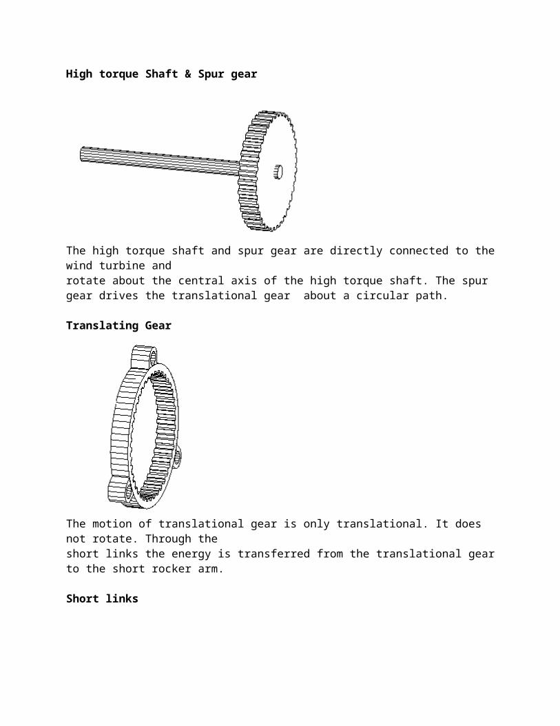
High torque Shaft & Spur gear
The high torque shaft and spur gear are directly connected to the wind turbine androtate about the central axis of the high torque shaft. The spur gear drives the translational gear about a circular path.
Translating Gear
The motion of translational gear is only translational. It does not rotate. Through theshort links the energy is transferred from the translational gear to the short rocker arm.
Short links
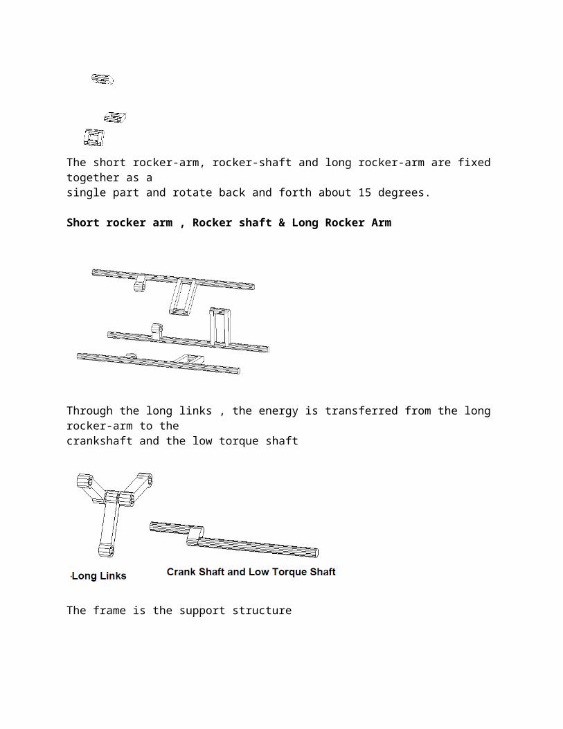
The short rocker-arm, rocker-shaft and long rocker-arm are fixed together as asingle part and rotate back and forth about 15 degrees.
Short rocker arm , Rocker shaft & Long Rocker Arm
Through the long links , the energy is transferred from the long rocker-arm to thecrankshaft and the low torque shaft
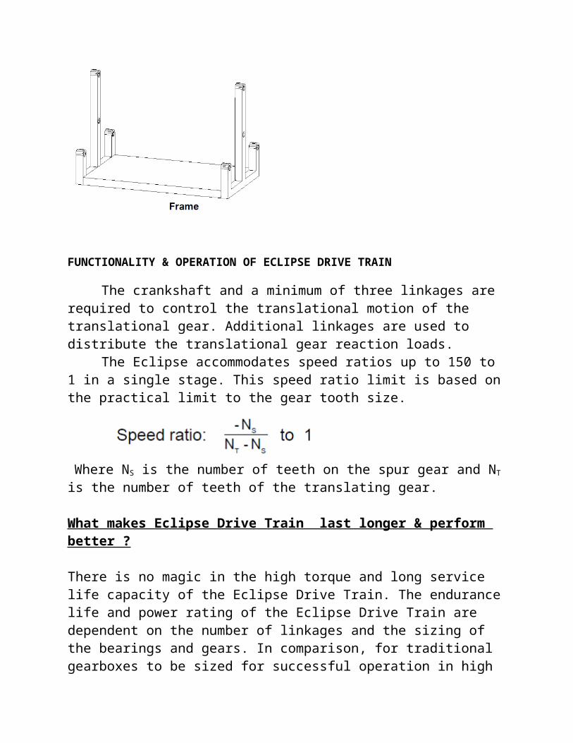
The frame is the support structure
FUNCTIONALITY & OPERATION OF ECLIPSE DRIVE TRAIN
The crankshaft and a minimum of three linkages are required to control the translational motion of the translational gear. Additional linkages are used to distribute the translational gear reaction loads.
The Eclipse accommodates speed ratios up to 150 to 1 in a single stage. This speed ratio limit is based on the practical limit to the gear tooth size.
Where NS is the number of teeth on the spur gear and NT is the number of teeth of the translating gear.
What makes Eclipse Drive Train last longer & perform better ?
There is no magic in the high torque and long service life capacity of the Eclipse Drive Train. The endurance life and power rating of the Eclipse Drive Train are dependent on the number of linkages and the sizing of the bearings and gears. In comparison, for traditional gearboxes to be sized for successful operation in highpower wind turbines, their cost, weight and size would be prohibitive.
The linkages are designed with respect to manufacturing tolerances, joint free play and stiffness to maintain evenly distributed linkage loads throughout the Eclipse system, regardless of the loads applied to the windmill blades. The linkages act in parallel to distribute the translational gear loads. The gear loads are distributed over multiple bearings. The bearings in the linkages rotate back and forth about 15 degrees.
Only the bearings on the crankshaft and the alignment bearings for the high and low torque shafts rotate a complete 360 degrees.The amplitude of the gear tooth stresses are substantially reduced due to the loads being distributed over a greater number of teeth The lower gear tooth stressesSubstantially increase the fatigue life of the gears.
What makes Eclipse Drive more Efficient ?The mechanical design efficiency of the Eclipse Drive train results in significantly greater efficiency than traditional planetary gearboxes, due to the reduced number of energy
dissipating components and to the fact that energy travels though only one set of gears and bearings.
There are two primary components that dissipate energy in a gearbox system: the gear tooth contact and the bearing contact. A basic rule of thumb in gearbox design for energy loss through gear tooth contact is approximatelyone half of one percent (1/2 of 1%) for every stage of gear interaction that the energypasses through. Bearing contacts contribute energy loss through rolling motion. The linkage bearings in the Eclipse are small in size in relation to traditional gearbox bearings and rotate back and forth about 15 degrees, producing only minimal energy losses. Only the crankshaft bearings rotate a complete 360 degrees and are similarly relatively small in size. Traditional gearbox systems routinely sufferenergy losses amounting to four to five percent (4-5%) due to multiple stage planetary gear sets and massive bearings. The Eclipse gearbox will operate with a totalmechanical efficiency of approximately 99 percent. Until this claim is validated by testing, a conservative estimate would be a mechanical efficiency no less than 98 percent.
Endurance Life, Size and Weight of Eclipse Drive TrainThe long endurance life, small size and light weight are the
primary strengths of the Eclipse Gearbox. Its size is equivalent to a traditional gearbox with half the weight. Even with half the weight, the Eclipse Gearbox handles greater torque loads with gears and bearings selected to handle all the requirements of the most challenging wind turbine applications, while maintaining endurance over a greaterlength of time. Gear tooth contact stress is substantially lower due the increase in the number of gear teeth that are simultaneously engaged. The decreased tooth contact stress directly increases the endurance life and torque capacity of the gears.
Refferences1.Modeling and Control of wind turbines using a Continuously Variable Transmission-M.J. Verdonschot DCT 2009.028
2. US Patent #1,613,344 "Power Transmission" -George Constantinesco
3. Trends in wind turbine drive trains - Dipl. Ing. ETH Hanspeter Dinner, EES KISSsoft GmbH, Switzerland