EchoSonic II MN300610 Rev A 09 JUL 0809 JUL 09 EchoSonic II 5 of 26 Rev A MN300610 Introduction: The...
26
09 JUL 09 EchoSonic II 1 of 26 Rev A MN300610 EchoSonic II Manual 09 JUL 08 Revision A Flowline Inc. 10500 Humbolt Street Los Alamitos, CA 90720 Tel: (562) 598-3015 Fax: (562) 431-8507 www.flowline.com
Transcript of EchoSonic II MN300610 Rev A 09 JUL 0809 JUL 09 EchoSonic II 5 of 26 Rev A MN300610 Introduction: The...

09 JUL 09 EchoSonic II 1 of 26 Rev A MN300610
EchoSonic II Manual
09 JUL 08 Revision A
Flowline Inc. 10500 Humbolt Street
Los Alamitos, CA 90720 Tel: (562) 598-3015 Fax: (562) 431-8507
www.flowline.com

2 of 26 EchoSonic II 09 JUL 08 MN300610 Rev A
09 JUL 09 EchoSonic II 3 of 26 Rev A MN300610
Preface This manual explains how to use the EchoSonic II, LU27 LU28 and LU29 series level transmitter. Warranty, Service & Repair To register your product with the manufacturer, go to the Flowline website for on-line registration. The website address is as follows:
www.flowline.com On-line Warranty Registration can be found under Contact Us in the Navigation Bar along the side of the home page. If for some reason your product must be returned for factory service, go to the Flowline website to receive a Material Return Authorization number (MRA), providing the following information:
1. Full Part Number, Full Serial Number 2. Name and telephone number of someone who can answer technical questions related
to the product and its application. 3. Return Shipping Address 4. Brief Description of the Symptom 5. Brief Description of the Application
On-line Material Return Authorization can be found under Contact Us in the Navigation Bar along the side of the home page. Click on Return Authorization to begin the MRA request. Once you have received a MRA number, ship the product prepaid in its original packing to:
Flowline Factory Service MRA_____ 10500 Humbolt Street Los Alamitos, CA 90720
To avoid delays in processing your repair, write the MRA on the shipping label. Please include the information about the malfunction with your product. This information enables our service technicians to process your repair order as quickly as possible.
4 of 26 EchoSonic II 09 JUL 08 MN300610 Rev A
Warranty Flowline warrants to the original purchaser of its products that such products will be free from defects in material and workmanship under normal use and service for a period which is equal to the shorter of one year from the date of purchase of such products or two years from the date of manufacture of such products. This warranty covers only those components of the products which have non-moving and not subject to normal wear. Moreover, products which are modified or altered, and electrical cables which are cut to length during installation are not covered by this warranty. Flowline’s obligation under this warranty is solely and exclusively limited to the repair or replacement, at Flowline’s option, of the products (or components thereof) which Flowline’s examination proves to its satisfaction to be defective. FLOWLINE SHALL HAVE NO OBLIGATION FOR CONSEQUENTIAL DAMAGES TO PERSONAL OR REAL PROPERTY, OR FOR INJURY TO ANY PERSON. This warranty does not apply to products which have been subject to electrical or chemical damage due to improper use, accident, negligence, abuse or misuse. Abuse shall be assumed when indicated by electrical damage to relays, reed switches or other components. The warranty does not apply to products which are damaged during shipment back to Flowline’s factory or designated service center or are returned without the original casing on the products. Moreover, this warranty becomes immediately null and void if anyone other than service personnel authorized by Flowline attempts to repair the defective products. Products which are thought to be defective must be shipped prepaid and insured to Flowline’s factory or a designated service center (the identity and address of which will be provided upon request) within 30 days of the discovery of the defect. Such defective products must be accompanied by proof of the date of purchase. Flowline further reserves the right to unilaterally waive this warranty and to dispose of any product returned to Flowline where: a. There is evidence of a potentially hazardous material present with product. b. The product has remained unclaimed at Flowline for longer than 30 days after dutifully requesting disposition of the product. THERE ARE NO WARRANTIES WHICH EXTEND BEYOND THE DESCRIPTION ON THE FACE OF THIS WARRANTY. This warranty and the obligations and liabilities of Flowline under it are exclusive and instead of, and the original purchaser hereby waives, all other remedies, warranties, guarantees or liabilities, express or implied. EXCLUDED FROM THIS WARRANTY IS THE IMPLIED WARRANTY OF FITNESS OF THE PRODUCTS FOR A PARTICULAR PURPOSE OR USE AND THE IMPLIED WARRANTY OF MERCHANTABILITY OF THE PRODUCTS. This warranty may not be extended, altered or varied except by a written instrument signed by a duly-authorized officer of Flowline, Inc.
09 JUL 09 EchoSonic II 5 of 26 Rev A MN300610
Introduction: The EchoSonic II is a general-purpose ultrasonic level transmitter that provides a loop powered 4-20 mA output. The 4-20 mA output can be used to provide the proportional level of liquid in any tank or vessel. The signal can be connected to any device that accepts a loop powered 4-20 mA signal, such as a PLC, SCADA, DCS, display, controller, etc. New Features
• Simple configuration with WebCal software, no more target calibration. • Adjustable Loop Fail-Safe, Hold Last, Empty, Full, 21 mA, 22 mA • Easy to reverse mA output, 4-20 mA to 20-4 mA • Adjustable start-up condition, Empty, Mid (12 mA), Full, Over range (22 mA) • Increased output filtering
Table of Contents Introduction ............................................................................................................................5 New Features ............................................................................................................................5 About this manual ......................................................................................................................6 Specifications ............................................................................................................................8 Dimensions ............................................................................................................................8 Getting Started ...........................................................................................................................9 USB® Fob Interface ....................................................................................................10 WebCal ........................................................................................................................11 Step 1: Configuration .......................................................................................12 Step 2: Tank Levels .........................................................................................14 Step 3: Write to Unit ........................................................................................14 Wiring ..........................................................................................................................15 Wiring Diagram ...........................................................................................................15 Wiring EchoSonic II ....................................................................................................15 Installation ..........................................................................................................................17 Position and Mount ......................................................................................................17 Mounting Guide ...........................................................................................................18 Fitting Selection ...........................................................................................................18 Tank Adapter: ..................................................................................................18 Riser .................................................................................................................19 Flange ...............................................................................................................19 Side Mount Fitting ...........................................................................................19 Stand Pipe ........................................................................................................20 Advanced Feature ....................................................................................................................21 Appendix ..........................................................................................................................23 Updating WebCal Software .........................................................................................23 Updating Transmitter Firmware ..................................................................................24 Factory Defaults ...........................................................................................................25 Troubleshooting ...........................................................................................................26

6 of 26 EchoSonic II 09 JUL 08 MN300610 Rev A
About this Manual: PLEASE READ THE ENTIRE QUICK START PRIOR TO INSTALLING OR USING THIS PRODUCT. This manual includes information on the EchoSonic II series Ultrasonic Level Switch from FLOWLINE. Please refer to the part number located on the switch label to verify the exact model configuration, which you have purchased. User’s Responsibility for Safety: FLOWLINE manufactures a broad range of level sensing technologies. While each of these sensors is designed to operate in a wide variety of applications, it is the user’s responsibility to select a sensor model that is appropriate for the application, install it properly, perform tests of the installed system, and maintain all components. The failure to do so could result in property damage or serious injury. Proper Installation and Handling: Only properly trained staff should install and/or repair this product. Install the transmitter with the included Viton gasket and never over tighten the transmitter within the fitting. Always check for leaks prior to system start-up. Wiring and Electrical: A supply voltage of 14 to 28 VDC is used to power the EchoSonic II. Electrical wiring of the transmitter should be performed in accordance with all applicable national, state, and local codes. Material Compatibility: The enclosure is made of Polycarbonate (PC). The transducer is made of Polyvinylidene Fluoride (PVDF). Make sure that the model, which you have selected, is chemically compatible with the application media. Enclosure: While the transmitter housing is liquid-resistant the EchoSonic II is not designed to be operational when immersed. It should be mounted in such a way that the enclosure and transducer do not come into contact with the application media under normal operational conditions. Safety • Installation should be done by properly trained staff • Supply voltage should never exceed a maximum of 28 VDC • Make sure the sensor is chemically compatible with your application • Design a fail-safe system that accommodates the possibility of sensor and/or power failure. • This sensor should not be used in classified hazardous environments Make a Fail-Safe System: Design a fail-safe system that accommodates the possibility of transmitter and/or power failure. FLOWLINE recommends the use of redundant backup systems and alarms in addition to the primary system. Flammable, Explosive or Hazardous Applications: EchoSonic II should not be used within classified hazardous environments. Warning: Always use the Viton gasket when installing the EchoSonic II, and make sure that all electrical wiring of the switch is in accordance with applicable codes.

09 JUL 09 EchoSonic II 7 of 26 Rev A MN300610
Components: EchoSonic II is offered in three different models. Depending on the model purchased, you may or may not have been shipped all the components shown below. You do however, need an EchoSonic II, USB® Fob and Viton® gasket to configure, install and operate EchoSonic II. • EchoSonic II
o LU27-01 – 8.2’ (2.5 m) range, Type 6P encl., 1” NPT o LU27-11 – 8.2’ (2.5 m) range, Type 6P encl., 1” G o LU28-01 – 24.6’ (7.5 m) range, Type 6P encl., 2” NPT o LU28-11 – 24.6’ (7.5 m) range, Type 6P encl., 2” G o LU29-01 – 32.8’ (10 m) range, Type 6P encl., 2” NPT o LU29-11 – 32.8’ (10 m) range, Type 6P encl., 2” G
• Viton Gasket o Part #200128 for LU27-01 or LU27-11 o Part #220129 for LU28-01, LU28-11, LU29-01 or LU29-11
• USB® Fob o Part #LI99-1001
• Quick Start Guide

8 of 26 EchoSonic II 09 JUL 08 MN300610 Rev A
Specifications: Range: LU27: 4" to 8.2' (10 cm to 2.5m) LU28: 8" to 24.6' (20 cm to 7.5m) LU29: 8" to 32.8' (20 cm to 10m) Accuracy: ± 0.2% @ Max. Range Resolution: LU27: 0.039” (1 mm) LU28/29: 0.079” (2 mm) Beam width: LU27: 2” (5 cm) dia. LU28/29: 3" (7.6 cm) dia. Dead band: LU27: 4” (10 cm) LU28/29: 8” (20 cm) Memory: Non-volatile Supply voltage: 24 VDC Consumption: 0.5 W Loop resistance: 500 Ohms @ 24 VDC
Signal output: 4-20 mA, two-wire Signal invert: 4-20 mA or 20-4 mA Configuration: WebCal® PC Windows®
USB 2.0
Fail-safety: 4 mA, 20 mA, 21 mA, 22 mA or hold last Process temp.: F: -4° to 140° C: -20° to 60° Temp. comp.: Automatic Ambient temp.: F: -31° to 140° C: -35° to 60° Pressure: MWP = 30 PSI Enclosure type: Type 6P encapsulated,
corrosion resistance & submersible
Encl. material: Polycarbonate Trans. material: PVDF Cable jacket mat.: Polyurethane Cable type: 4-cond., shielded Cable length: 10’ (3 m) Process mount: LU27: 1” NPT (1” G) LU28/29: 2” NPT (2” G) Mount. gasket: Viton® Classification: General purpose Compliance: RoHS Approvals: CE, cFMus
Dimensions:
Side View / LU27 Series
Side View / LU28 and LU29 Series

09 JUL 09 EchoSonic II 9 of 26 Rev A MN300610
Getting Started: EchoSonic II is configured through WebCal, a PC software program. WebCal is a free download from Flowline’s website. You must download and install WebCal prior to plugging in the USB® Fob. Please go to http://www.flowline.com/webcal and select download.
WebCal System Requirements Windows® XP or 2000 10 mB hard drive space
256 mB RAM 1 USB® 2.0 port
Internet connection
10 of 26 EchoSonic II 09 JUL 08 MN300610 Rev A
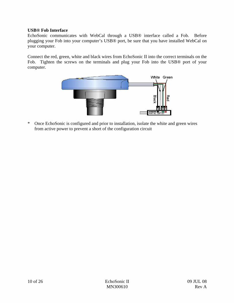
USB® Fob Interface EchoSonic communicates with WebCal through a USB® interface called a Fob. Before plugging your Fob into your computer’s USB® port, be sure that you have installed WebCal on your computer. Connect the red, green, white and black wires from EchoSonic II into the correct terminals on the Fob. Tighten the screws on the terminals and plug your Fob into the USB® port of your computer.
* Once EchoSonic is configured and prior to installation, isolate the white and green wires
from active power to prevent a short of the configuration circuit

09 JUL 09 EchoSonic II 11 of 26 Rev A MN300610
WebCal With EchoSonic II connected to your computer, open the WebCal software by clicking on the WebCal icon. Follow steps 1-3 to configure the transmitter. Click “Help” in the lower right hand corner and open the help menu of WebCal for additional instructions on WebCal. If you need additional assistance using WebCal, please contact a Flowline Applications engineer at (562) 598-3015.

12 of 26 EchoSonic II 09 JUL 08 MN300610 Rev A
WebCal Step 1: Configuration This section of WebCal is where you select the application’s configuration settings. Start from the top and work to the bottom, choosing the selections that are applicable to your configuration. “Not Applicable” will automatically show when a selection doesn’t apply to your configuration settings, and you may move on. All configuration settings must be selected or have “Not Applicable” before you can continue to step 2.
Loop Fail-Safe This feature allows you to select the fail-safe current output if the sensor fails to detect a return signal. When the sensor regains signal, the output current will revert back to the current level condition.
o Hold Last Value - The output will remain in the same state as the last echo detected. Example: If the output was 6.7 mA just prior to the lost signal, the device will continue to output 6.7 mA. When the sensor regains signal, the output will indicate the level when the signal was regain.
o Empty - The output will revert to the current value for a Empty condition. The empty state is dependent upon the Output at Empty setting. When 4 mA at Bottom is selected, the sensor will output 4 mA when a fail-safe condition occurs. If 20 mA at Bottom is selected, the sensor will output 20 mA when a fail-safe condition occurs
o Full - The output will revert to the current value for a Full condition. The full state is dependent upon the Output at Empty setting. When 4 mA at Bottom is selected, the sensor will output 20 mA when a fail-safe condition occurs. If 20 mA at Bottom is selected, the sensor will output 4 mA when a fail-safe condition occurs
o Overfill (21mA) - The output current will go to 21mA when the return signal is lost.
o Overfill (22mA) - The output current will go to 22mA when the return signal is lost.
Right click on any menu that you may have questions on to open the help menu.

09 JUL 09 EchoSonic II 13 of 26 Rev A MN300610
Output at Empty This feature allows you to select the orientation of the 4 to 20mA output (4 to 20 mA or 20 to 4 mA). Choose which output setting best fits the application. Typical installations are set with 4 mA at Bottom. This will not affect the performance of the sensor other than the output of the EchoSonic II. WebCal’s factory default is 4mA at bottom and 20mA at top. When connecting your sensor to a display, you must account for your output settings.
o 4mA at Bottom - The output current will be 4mA when the sensor measures an empty tank and 20mA when the sensor measures a full tank.
o 20mA at Bottom - The output current will be 20mA when the sensor measures an empty tank and 4mA when the sensor measures a full tank
Startup Condition This feature allows the operator to select the output current on initial startup prior to acquiring a true return signal (level measurement). This only occurs during the initial powering of EchoSonic II and the transmitter will revert to the correct level reading when the level is acquired.
o Empty - Selects the start up current established in Output at Empty. Example: Select 4 mA at Bottom, the output will remain at 20 mA until the unit acquires a true return echo. Select 20 mA at Bottom, the output will remain at 20 mA until the unit acquires a true return echo.
o Mid Tank - When selected, the startup current will read 12 mA until the unit acquires a true return echo.
o Full Tank - Uses the opposite current that was selected in Output at Empty. Example: If you select 4 mA at Bottom then the start up current would be 20 mA. If you select 20 mA at Bottom then the start up current would be 4 mA.
o Overfill (22mA) - The output at startup would be 22 mA. This condition will remain until the unit acquires a true return echo.

14 of 26 EchoSonic II 09 JUL 08 MN300610 Rev A
WebCal Step 2: Tank Levels This section of WebCal is where you enter application measurement values. All values must be filled in before moving to step 3.
Sensor Height: Distance from the bottom of the tank to the bottom of the transducer. Fill Height: Distance from the bottom of the tank to the maximum liquid height.
WebCal Step 3: Write to Unit After you have entered configurations and tank values, click “Write to Unit” and send the configuration to your EchoSonic. Now use WebCal’s file management features to save your configuration by clicking “Save Config File” and print your wiring diagram by clicking “Wiring Diagram.”
Write to Unit Wiring diagram
Save Config File

09 JUL 09 EchoSonic II 15 of 26 Rev A MN300610
Wiring Diagram
Wiring EchoSonic After you have finished positioning and mounting EchoSonic II, follow WebCal’s wiring diagram to wire EchoSonic II. Flowline recommends using a qualified licensed electrician to wire EchoSonic II and your application’s components. Note: Do not extend the White & Green wires beyond 15’. Note: Once EchoSonic is configured, isolate the white and green wires from active power to prevent a short of the configuration circuit.

16 of 26 EchoSonic II 09 JUL 08 MN300610 Rev A
09 JUL 09 EchoSonic II 17 of 26 Rev A MN300610
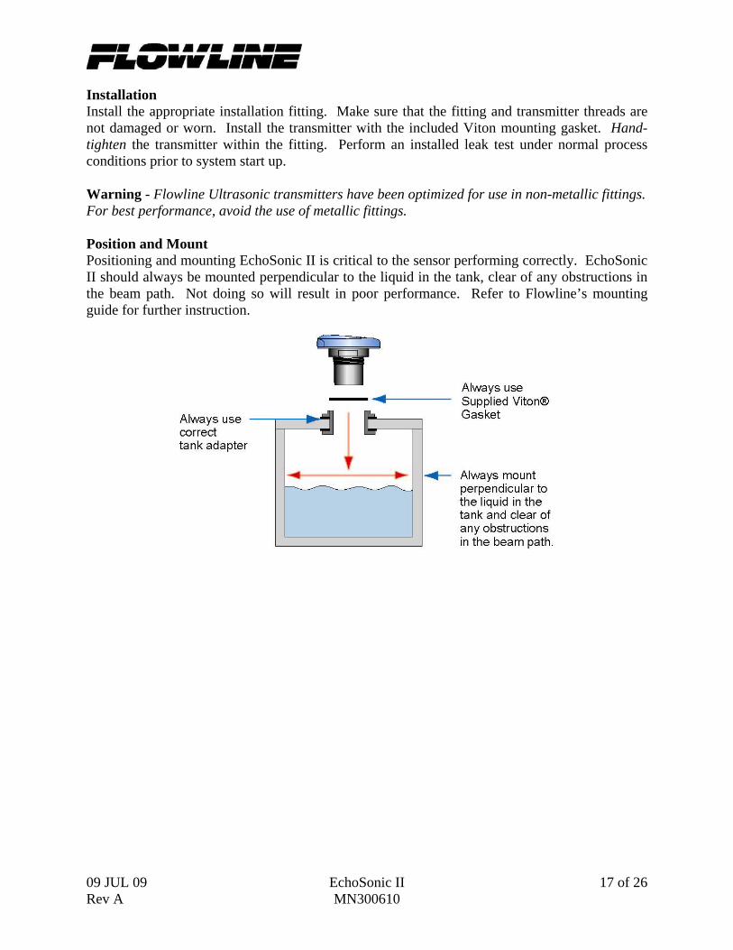
Installation Install the appropriate installation fitting. Make sure that the fitting and transmitter threads are not damaged or worn. Install the transmitter with the included Viton mounting gasket. Hand-tighten the transmitter within the fitting. Perform an installed leak test under normal process conditions prior to system start up. Warning - Flowline Ultrasonic transmitters have been optimized for use in non-metallic fittings. For best performance, avoid the use of metallic fittings. Position and Mount Positioning and mounting EchoSonic II is critical to the sensor performing correctly. EchoSonic II should always be mounted perpendicular to the liquid in the tank, clear of any obstructions in the beam path. Not doing so will result in poor performance. Refer to Flowline’s mounting guide for further instruction.

18 of 26 EchoSonic II 09 JUL 08 MN300610 Rev A
Mounting Guide 1. Do not mount at an angle 2. Liquid should never enter the dead band 3. Mount at least 2” from the side wall 4. Do not mount where obstacles will intrude on 2” beam width 5. Do not mount in a vacuum 6. Never screw directly into tank, always use a non-metallic fitting 7. Always use a tank adapter with the minimal height possible
Do not install at
angle relative to the liquid.
Do not install within 3” of tank sidewall.
Do not install with objects in the beam.
Do not install in applications with
vacuum.
Fitting Selection: Check the part number to determine the required fitting mount size and thread type. EchoSonic II is commonly installed in tank adapters, flanges, brackets or standpipes. Note: Always include the gasket when installing the EchoSonic II.
1. Tank Adapter: Select a tank adapter fitting with minimal height so as to ensure that the installed transducer will not be substantially elevated into the fitting such as the Hayward 2” Tank Adapter (socket by thread). For the LU27 series, add a Reducer Bushing such as the Spears 2” x 1”, thread x thread, Reducer Bushing (series 839-249, Flowline p/n LM52-1001). Avoid tank adapter (thread x thread) styles and/or pipe stops forward of the installed transducer.
2” Tank Adapter Socket x Thread
Tank Adapter w/ 2”x1” Reducer Bushing
Tank Adapter Thread x Thread
Do not use thread x thread

09 JUL 09 EchoSonic II 19 of 26 Rev A MN300610
2. Riser: Installations with tall, narrow risers can impede the acoustic signal. Select a fitting with the right riser height versus inner diameter geometry.
3. Flange: If installing on a flange, select a flange with a thread that is above the plane of the flange, such as the Spears 2” One Piece Flange (series 852-020). Avoid the use of blind flanges with tapped threads or flanges where the threads are even with the plane of the flange, such as the Banjo 2" Poly ANSI Flange (series AF200).
2” Flange w/
thread out of plane 2” Flange w/
thread in plane 2” Flange w/
Reducer Bushing
Do not use thread in plane
If the installation requires the use of a blind flange, tap a thread 1” larger than the sensors thread and add a Reducer Bushing such as a Spears thread x thread Reducer Bushing [Use the 439-338 (3” x 2”) for LU28/LU29 series or 439-249 (2” x 1”) for LU27 series].
4. Side Mount Bracket: The LM50-1001 side mount bracket or equivalent can be used for open tank top installations against the sidewall. For the LU27 series, order the LM50-1001-1, which includes a 2”x 1” Reducer Bushing.

20 of 26 EchoSonic II 09 JUL 08 MN300610 Rev A
5. Stand Pipe: A standpipe maybe used to dampen turbulence. Flowline recommends using a standpipe when foam is present in the application. Select a 2” pipe for the LU27 series and a 3” pipe for all other models. The pipe length should run the measurement span. Cut a 45°notch at the bottom of the pipe and drill a 1/4”pressure equalization hole high in the dead band.
6. Reducer Bushings: A reducer bushing can be used to decouple the EchoSonic II from metallic fittings or flanges with threads in the plane or to connect the transmitter to a larger stand pipe.
Flowline P/N Hayward P/N Description LM52-1400 439-249 2" Thread x 1" Thread,
PVC, Sch 40 LM52-1410 438-249 2" Socket x 1" Thread,
PVC, Sch 40 LM52-2400 439-338 3" Thread x 2" Thread,
PVC, Sch 40 LM52-2410 438-338 3" Socket x 2" Thread,
PVC, Sch 40 Thread x Thread Socket x Thread Reducer Bushing Reducer Bushing
09 JUL 09 EchoSonic II 21 of 26 Rev A MN300610
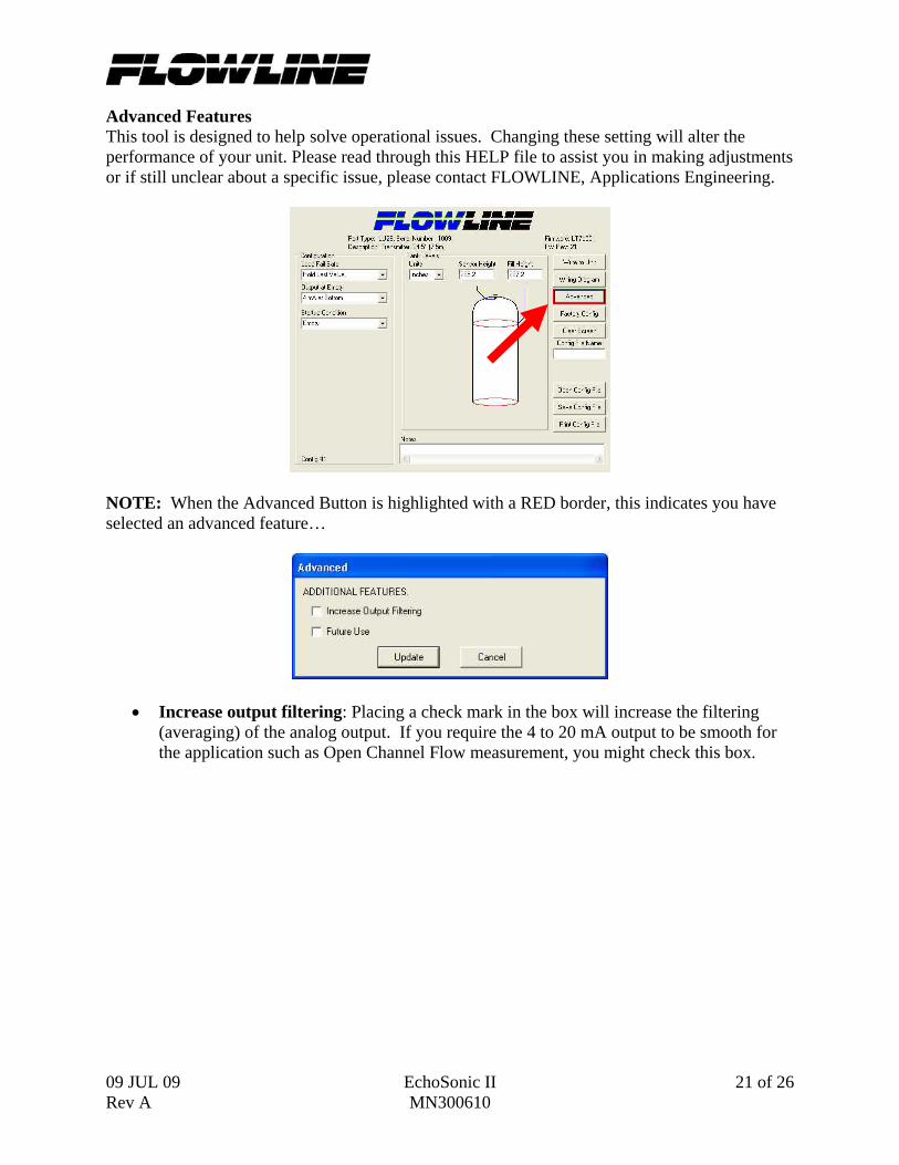
Advanced Features This tool is designed to help solve operational issues. Changing these setting will alter the performance of your unit. Please read through this HELP file to assist you in making adjustments or if still unclear about a specific issue, please contact FLOWLINE, Applications Engineering.
NOTE: When the Advanced Button is highlighted with a RED border, this indicates you have selected an advanced feature…
• Increase output filtering: Placing a check mark in the box will increase the filtering (averaging) of the analog output. If you require the 4 to 20 mA output to be smooth for the application such as Open Channel Flow measurement, you might check this box.

22 of 26 EchoSonic II 09 JUL 08 MN300610 Rev A

09 JUL 09 EchoSonic II 23 of 26 Rev A MN300610
Appendix Updating WebCal Software WebCal software can be updated directly from the software. Simply click on the Updates Tab at the top of the window and press the WebCal button. Make sure that your computer has access to the Internet. If not, an error window will appear. When the WebCal button is pressed, the software will check the version of software you re using with the most recent version at Flowline. If the versions are similar, a window indicating that the most recent version is installed. If not, then a window will appears asking to download the latest version. Follow the instructions for installing the latest version.

24 of 26 EchoSonic II 09 JUL 08 MN300610 Rev A
Updating Transmitter Firmware WebCal software can also be used to update the firmware inside the EchoSonic II transmitter. This feature allows the transmitter to be updated when new features are added. First open WebCal with an EchoSonic II transmitter connected and the latest version of WebCal downloaded to your PC.
Click on the Updates Tab and then click on Browse to select the Firmware update.
Select the latest version of the firmware (*.fep) file and click on Open. To identify the latest version, look in the part number and the version will be after the letters “ver”.
Confirm that the address is correct and then click on Update Sensor to begin the firmware update. This step should take less than 1 minute. You can follow the progress with the status bar to the right of the Update Sensor button. When completed, click on the Configuration tab to configure the transmitter. Remember, when the Firmware has been updated, the unit will return to its original factory settings.
09 JUL 09 EchoSonic II 25 of 26 Rev A MN300610
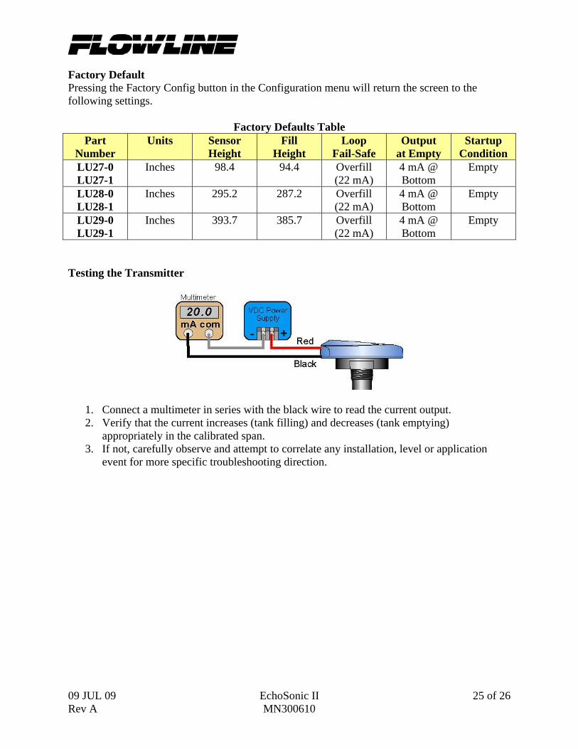
Factory Default Pressing the Factory Config button in the Configuration menu will return the screen to the following settings.
Factory Defaults Table Part
Number Units Sensor
Height Fill
Height Loop
Fail-Safe Output
at Empty Startup
Condition LU27-0 LU27-1
Inches 98.4 94.4 Overfill (22 mA)
4 mA @ Bottom
Empty
LU28-0 LU28-1
Inches 295.2 287.2 Overfill (22 mA)
4 mA @ Bottom
Empty
LU29-0 LU29-1
Inches 393.7 385.7 Overfill (22 mA)
4 mA @ Bottom
Empty
Testing the Transmitter
1. Connect a multimeter in series with the black wire to read the current output. 2. Verify that the current increases (tank filling) and decreases (tank emptying)
appropriately in the calibrated span. 3. If not, carefully observe and attempt to correlate any installation, level or application
event for more specific troubleshooting direction.

26 of 26 EchoSonic II 09 JUL 08 MN300610 Rev A
Troubleshooting
PROBLEM SOLUTION Transmitter indicates a current of 0 mA
Check the wiring for an open circuit. An open circuit is the most common issue with a 0 mA signal
Transmitter jumps to a current reading between 19 and 20 mA
Check the installation of the transmitter. Bad installation fittings will cause false signals near the top of the tank, which typically translates to a signal between 19 and 20 mA. Also look for interference just below the transmitter. If the transmitter is installed in a metal fitting, switch to a plastic fitting.
Transmitter indicates a current over 23 mA
Immediately check the wiring for a short circuit. The EchoSonic II is current limited to 22 mA. Anything above 23 mA indicates a short circuit.
Transmitter always jumps to LOST condition
Check the dimensional configuration (Height and Fill H) of the EchoSonic II. Make sure that the Fill H setting corresponds to the full level of liquid (from the bottom up) and not the distance from the transmitter to the liquid (top down).
Output of transmitter is opposite of the level of liquid
Check the Output at Empty Setting. Make sure the setting is correct (4mA at bottom or 20 mA at bottom).
No Unit Detected in WebCal
WebCal cannot detect an EchoSonic II connected to the computer. Check that the Fob is connected to the USB port. Also check that all four wires (Red, Black, White and Green) are securely attached to the Fob.
Internet error. The server name or address could not be resolved.
This is a warning indicating the computer configuring EchoSonic II is not connected to the internet. Click OK to continue. Flowline recommends being connecting to the internet for all configurations. Not being connected to the internet will not prevent the EchoSonic II from being configured.