ECET 211 Electric Machines & Controls Lecture 4-2 …lin/ECET211/spring2016/1-Lectures/...ECET 211...
21
1 1 ECET 211 Electric Machines & Controls Lecture 4-2 Motor Control Devices: Part 3. Sensors Part 4. Actuators Text Book: Electric Motors and Control Systems , by Frank D. Petruzella, published by McGraw Hill, 2015. Paul I-Hai Lin, Professor of Electrical and Computer P.E. States of Indiana & California Dept. of Computer, Electrical and Information Technology Purdue University Fort Wayne Campus Prof. Paul Lin Lecture 4 Motor Control Devices Chapter 4. Motor Control Devices • Part 1. Manually Operated Switches • Part 2. Mechanically Operated Switches • Part 3. Sensors • Part 4. Actuators Prof. Paul Lin 2
Transcript of ECET 211 Electric Machines & Controls Lecture 4-2 …lin/ECET211/spring2016/1-Lectures/...ECET 211...

1
1
ECET 211 Electric Machines & Controls
Lecture 4-2 Motor Control Devices:Part 3. Sensors
Part 4. Actuators
Text Book: Electric Motors and Control Systems, by Frank D.
Petruzella, published by McGraw Hill, 2015.
Paul I-Hai Lin, Professor of Electrical and Computer
P.E. States of Indiana & California
Dept. of Computer, Electrical and Information Technology
Purdue University Fort Wayne Campus
Prof. Paul Lin
Lecture 4 Motor Control Devices
Chapter 4. Motor Control Devices
• Part 1. Manually Operated Switches
• Part 2. Mechanically Operated Switches
• Part 3. Sensors
• Part 4. Actuators
Prof. Paul Lin 2

2
Part 3 Sensors
Sensors
• Devices that are used to detect, and often to measure, the
magnitude of real world parameters such as distance, position
velocity, acceleration, temperature, sound, force, light, etc
• Operated by converting mechanical, magnetic, thermal, optical,
and chemical variations into electrical voltage and currents.
• Sensors are categorized by what they measure
Proximity Sensors, Photoelectric Sensors
Hall Effect Sensors, Ultrasonic Sensors
Temperature Sensors, Velocity and Position Sensors
Flow Measurement, Magnetic Flowmeters
• Play an important role in modern manufacturing process control
Prof. Paul Lin 3
Part 3 Sensors
Figure 4-33 Typical sensor Applications
• Light sensor
• Pressure sensor
• Bard code sensor (reader)
Prof. Paul Lin 4
3
Part 3 Sensors: Proximity Sensors
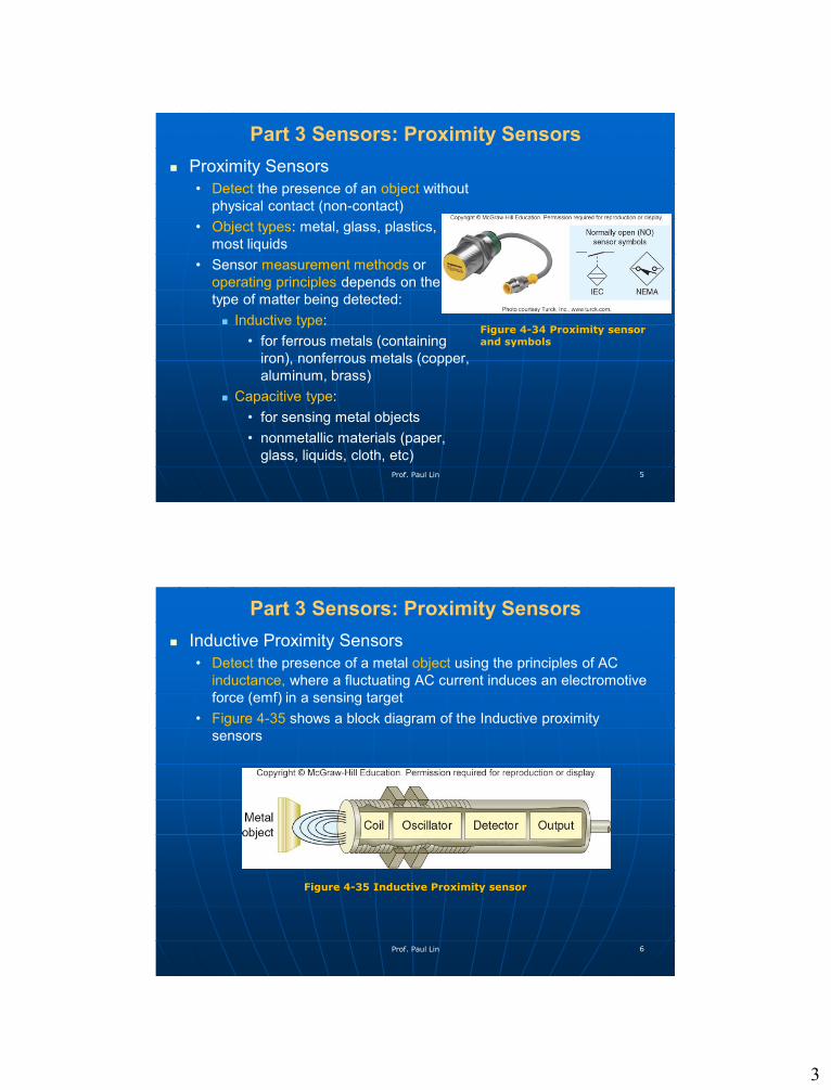
Proximity Sensors
• Detect the presence of an object without
physical contact (non-contact)
• Object types: metal, glass, plastics,
most liquids
• Sensor measurement methods or
operating principles depends on the
type of matter being detected:
Inductive type:
• for ferrous metals (containing
iron), nonferrous metals (copper,
aluminum, brass)
Capacitive type:
• for sensing metal objects
• nonmetallic materials (paper,
glass, liquids, cloth, etc)
Prof. Paul Lin 5
Figure 4-34 Proximity sensor and symbols
Part 3 Sensors: Proximity Sensors
Inductive Proximity Sensors
• Detect the presence of a metal object using the principles of AC
inductance, where a fluctuating AC current induces an electromotive
force (emf) in a sensing target
• Figure 4-35 shows a block diagram of the Inductive proximity
sensors
Prof. Paul Lin 6
Figure 4-35 Inductive Proximity sensor
4
Part 3 Sensors: Proximity Sensors
Inductive Proximity Sensors
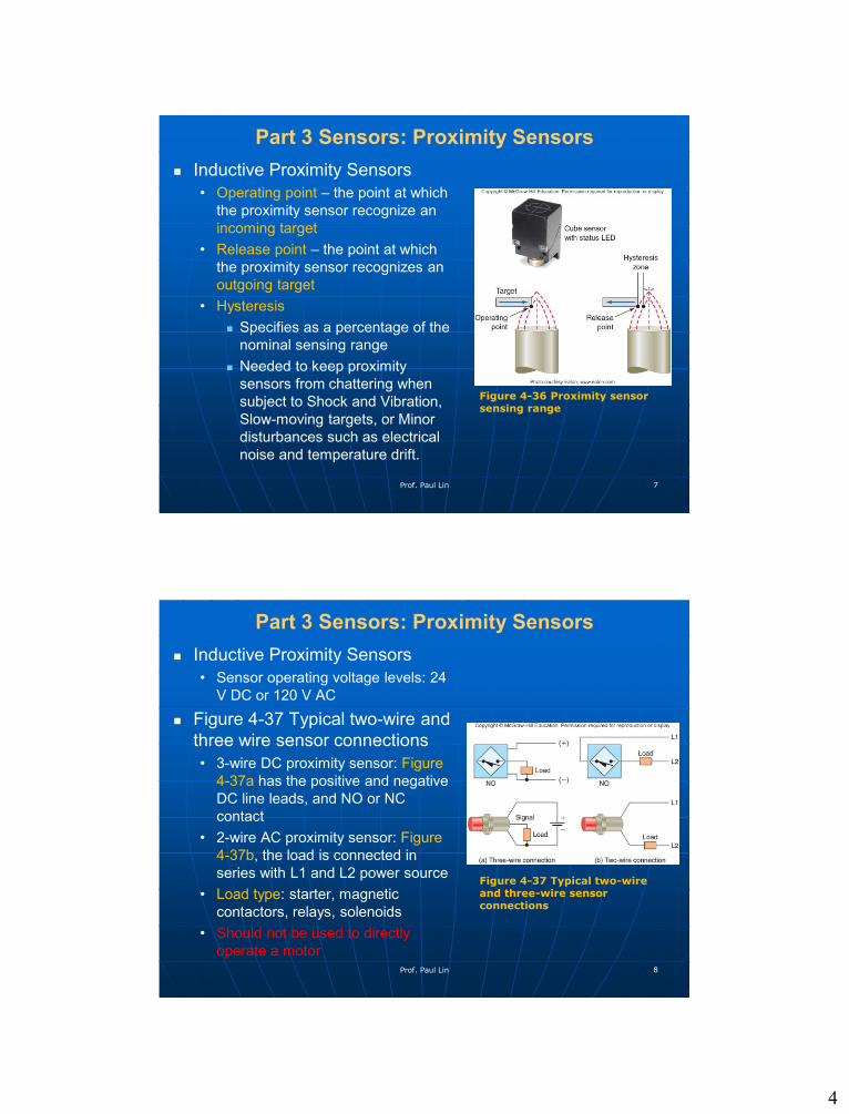
• Operating point – the point at which
the proximity sensor recognize an
incoming target
• Release point – the point at which
the proximity sensor recognizes an
outgoing target
• Hysteresis
Specifies as a percentage of the
nominal sensing range
Needed to keep proximity
sensors from chattering when
subject to Shock and Vibration,
Slow-moving targets, or Minor
disturbances such as electrical
noise and temperature drift.
Prof. Paul Lin 7
Figure 4-36 Proximity sensor sensing range
Part 3 Sensors: Proximity Sensors
Inductive Proximity Sensors
• Sensor operating voltage levels: 24
V DC or 120 V AC
Figure 4-37 Typical two-wire and
three wire sensor connections
• 3-wire DC proximity sensor: Figure
4-37a has the positive and negative
DC line leads, and NO or NC
contact
• 2-wire AC proximity sensor: Figure
4-37b, the load is connected in
series with L1 and L2 power source
• Load type: starter, magnetic
contactors, relays, solenoids
• Should not be used to directly
operate a motor Prof. Paul Lin 8
Figure 4-37 Typical two-wire and three-wire sensor connections

5
Proximity Sensors
Capacitive Proximity Sensors
• Detect the presence of a metal object using the principles of
capacitance (C = ε A/d); where C is the capacitance, ε is the
dielectric constant, A is the metal electrode area, and d is the
distance between the two electrodes
• Figure 4-38 Capacitive proximity sensor
Prof. Paul Lin 9
Proximity Sensors
Capacitive Proximity Sensors
• Figure 4-39 Capacitive proximity sensor liquid detection
• An application example for detecting empty container
Cardboard container: lower dielectric constant, εC
Liquid: higher dielectric constant, εLiquid
• Empty containers are automatically diverted via the push
rod
Prof. Paul Lin 10

6
Photoelectric Sensors
Photoelectric Sensors
• An optical control device that operates by detecting a visible or
non-visible beam of light and responding to a change in the
receiving light intensity.
• Two components: a transmitter (light source) and a receiver
(sensor), may or may not be housed in the same unit
• Figure 4-40 Photoelectric sensor
• Scan techniques to detect object
Through-Beam Scanning
Retro-reflective Scanning
Diffuse scanning
Fiber-optics
Prof. Paul Lin 11
Through-Beam Scanning Photoelectric Sensors
Direct scan, placed the
transmitter and receiver in
direct line with each other
Detect: Light being blocked -
Yes/No
Long range sensing: up to 300
feet
More reliable method in area
of heavy dust, mist, and other
types of airborne
contaminants
Figure 4-41 Through-beam
scan
An example: Garage door
opener
Prof. Paul Lin 12

7
Photoelectric Sensors
Retro-reflective Scan Sensor
(Figure 4-42)
• The transmitter and receiver
are housed in the same
enclosure
• Used for medium-range
applications
• May not be able to detect shiny
targets
• Because it cannot differentiate
the Light reflective back from
the reflector vs. Light reflective
back from the target
Polarized Retro-reflective Scan
Sensor (Figure 4-43): Over come
this problem
Prof. Paul Lin 13
Photoelectric Sensors
Diffuse Scan Sensor
• The transmitter and receiver are housed in the same enclosure.
• A light reflector is not needed.
• Receiver picks up some of the diffused (scattered) light.
• Maximum sensing length: 40 inch
• Figure 4-44 Diffuse scan sensor: inspect the presence of the
polarity mark on a capacitor (or any other mark inspection)
Prof. Paul Lin 14
8
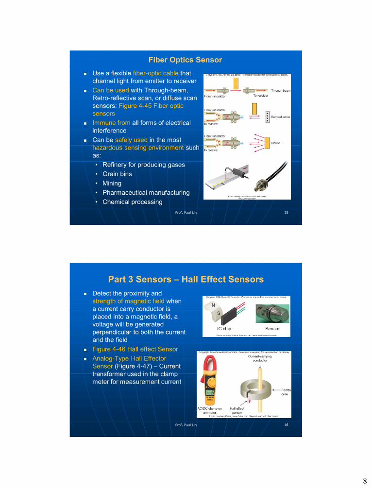
Fiber Optics Sensor
Use a flexible fiber-optic cable that
channel light from emitter to receiver
Can be used with Through-beam,
Retro-reflective scan, or diffuse scan
sensors: Figure 4-45 Fiber optic
sensors
Immune from all forms of electrical
interference
Can be safely used in the most
hazardous sensing environment such
as:
• Refinery for producing gases
• Grain bins
• Mining
• Pharmaceutical manufacturing
• Chemical processing
Prof. Paul Lin 15
Part 3 Sensors – Hall Effect Sensors
Detect the proximity and
strength of magnetic field when
a current carry conductor is
placed into a magnetic field, a
voltage will be generated
perpendicular to both the current
and the field
Figure 4-46 Hall effect Sensor
Analog-Type Hall Effector
Sensor (Figure 4-47) – Current
transformer used in the clamp
meter for measurement current
Prof. Paul Lin 16
9
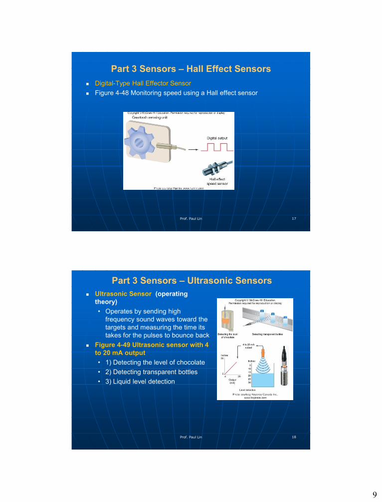
Part 3 Sensors – Hall Effect Sensors
Digital-Type Hall Effector Sensor
Figure 4-48 Monitoring speed using a Hall effect sensor
Prof. Paul Lin 17
Part 3 Sensors – Ultrasonic Sensors
Ultrasonic Sensor (operating
theory)
• Operates by sending high
frequency sound waves toward the
targets and measuring the time its
takes for the pulses to bounce back
Figure 4-49 Ultrasonic sensor with 4
to 20 mA output
• 1) Detecting the level of chocolate
• 2) Detecting transparent bottles
• 3) Liquid level detection
Prof. Paul Lin 18

10
Part 3 Sensors – Ultrasonic Sensors
Figure 4-50 Ultrasonic wind sensor
• Wind turbine system application for
determining wind speed and direction
• Four sensors, one at each major
compass point (N-S, E-W)
Operating Theory
• N S, E W: fire ultrasonic sound
pulses to opposing sensors
• In still air: all pulses’ time of flight are
equal
• Wind blow: it increases the time of
flight for pulses traveling against it
• System calculates the wind speed
and direction
Prof. Paul Lin 19
Part 3 Sensors – Temperature Sensors
Types of sensors
• Thermocouple:
High temperature measurement; output DC mV
Type B (870 °C to 1700 °C / 1000°F to 3100°F)
Type E (-200 °C to 900 °C / -330°F to 1600°F)
Type J (0 °C to 760 °C / 32°F to 1400°F)
Type K (-200 °C to 1260 °C / -330°F to 2300°F)
Types R, S, T, C, P
• Resistance Temperature Detector (RTD):
Positive temperature coefficient (PTC) R: Temp
increase => R increase
• Thermistor: negative temperature coefficient (NTC) R
• IC sensor
Prof. Paul Lin 20

11
Part 3 Sensors – Temperature Sensors
Types of sensors
• Thermistor:
Negative temperature coefficient (NTC) R
Temperature range: -100 °C to 500 °C
• IC sensor
RTD, Thermistor, Thermocouple Comparison Chart,
http://digital.ni.com/public.nsf/allkb/C50FA55B3B2F85D986257
2D00083350E
Prof. Paul Lin 21
Criteria Thermocouple RTD Thermistor
Temp Range -267 °C to 2316 °C -240 °C to 649 °C -100 °C to 500 °C
Accuracy Good Best Good
Linearity Better Best Good
Sensitivity Good Better Best
Cost Best Good Better
Part 3 Sensors – Temperature Sensors
Figure 4-51 Thermocouple
heat sensor
• Hot junction (measurement
junction)
• Cold junction (reference
junction)
• Type K (-200 °C to 1260 °C /
-330°F to 2300°F
• Hot junction at 300 °C =>
12.2 mV
Prof. Paul Lin 22

12
Part 3 Sensors – Temperature Sensors
Figure 4-52 Thermocouple tip
styles
Prof. Paul Lin 23
Figure 4-53 Typical thermowell
installation
Part 3 Sensors – Temperature Sensors
Resistance Temperature Detector (RTD):
• Positive temperature coefficient (PTC) R
• Temp increase => R increase
• Temperature Ranges: -50 ° C to 500 ° C for thin film RTD, -200
°C to 850 ° C for wire-wound RTD,
http://www.omega.com/temperature/pdf/rtd_gen_specs_ref.pdf
• Figure 4-54 Resistance temperature detector
Prof. Paul Lin 24

13
Part 3 Sensors – Temperature Sensors
Thermistors
• Thermally sensitive resistor
• NTC (Negative Temp
Coefficient): Temp increase,
R decrease
• Figure 4-55 Thermistors
IC Temperature Sensor
• Figure 4-56 Integrated circuit
temperature sensor
Prof. Paul Lin 25
Part 3 Sensors – Velocity & Position Sensors
Tachometer
• Figure 4-57 Tachometer
generator
Magnetic Pickup Sensor (Figure
4-58)
Encoder (Figure 4-9 Optical
encoder)
Prof. Paul Lin 26
Figure 4-58Figure 4-59

14
Part 3 Sensors – Flow Measurement
Turbine Flowmeters
• Like windmills utilizes their
angular velocity (rotational
speed) to indicate flow
velocity
• Figure 4-60
Target Flowmeters
• Measure the drag force on
the inserted target flat disk,
and convert it to the flow
velocity
• Figure 4-61
Prof. Paul Lin 27
Part 3 Sensors – Flow Measurement
Magnetic Flowmeters
• Electromagnetic flowmeters or induction flowmeters
• Obtained the flow velocity by measuring the changes of
induced voltage of the conductive fluid passing across a
controlled magnetic field
• Figure 4-62 Magnetic flowmeter
Prof. Paul Lin 28

15
Part 4 Actuators
Relays
Solenoids
Solenoid Valves
Stepper Motors
Servo Motors
Prof. Paul Lin 29
Part 4 Actuators
Actuator
• A device that converts electrical signal to mechanical movement.
Actuator Types
• Relays
• Solenoids
• Solenoid Valves
• Stepper Motors
• Servo Motors
Prof. Paul Lin 30
16
Part 4 Actuators Figure 4-63 Electromagnetic
relay
Prof. Paul Lin 31
Figure 4-64 Relay motor
control circuit
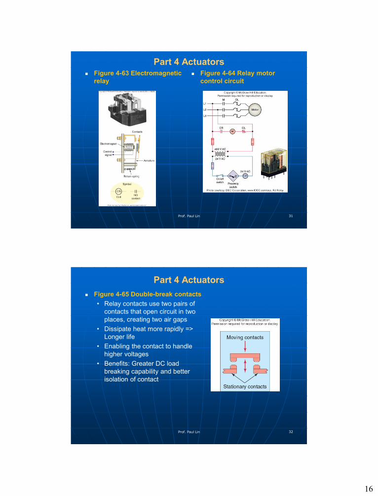
Part 4 Actuators
Figure 4-65 Double-break contacts
• Relay contacts use two pairs of
contacts that open circuit in two
places, creating two air gaps
• Dissipate heat more rapidly =>
Longer life
• Enabling the contact to handle
higher voltages
• Benefits: Greater DC load
breaking capability and better
isolation of contact
Prof. Paul Lin 32

17
Part 4 Actuators
Dry contact
• A dry contact refers to one that
has both terminals available and
in which neither contact is initially
connected to a voltage source
Figure 4-66 shows a magnetic
starter with an extra dry contact
Prof. Paul Lin 33
Part 4 Actuators
Solenoid
• A electromechanical
solenoid is a device that
uses electrical energy to
cause mechanical control
action
• A solenoid consists of
A coil
Frame
Plunger (or armature)
• Types: AC or DC solenoid
• Categories: Linear, Rotary
• Action: energized vs
deenergized
• Figure 4-67 Solenoid
construction and operationProf. Paul Lin 34

18
Part 4 Actuators
Solenoid
• A electromechanical
solenoid is a device that
uses electrical energy to
cause mechanical control
action
• A solenoid consists of a
coil, frame, plunger (or
armature), Figure 4-67
Solenoid construction and
operation
• Types: AC or DC solenoid
• Categories: Linear, Rotary;
Figure 4-68
• Actions: energized vs
deenergized
Prof. Paul Lin 35
Part 4 Actuators
Solenoid Valve
• A combination of a
solenoid coil operator and
value
• It controls the flow of
liquids, gases, steam, and
other media.
• Figure 4-69 Solenoid value
construction and principle
of operation
Prof. Paul Lin 36

19
Part 4 Actuators
Figure 4-70 Solenoid
valve operated tank
filling and empty
operation
• Tank filling operation:
Solenoid A
Fill tank sensor
Control relay
(1CR)
• Tank emptying :
Solenoid B
Empty tank sensor
Control relay
(2CR)
Prof. Paul Lin 37
Part 4 Actuators
Stepper Motors
• A brushless DC motor with the rotor
carries a set of permanent magnets,
and the stator has a set of coils.
Figure 4-72 Stepper Motor
operation
• The shaft of a stepper motor rotate
in discrete increments when
electrical command pulsed are
applied to it in proper sequence.
• An example: a stepper that 1.8
degree per pulse step, would take
200 pulses to make a 360 degree
rotation
• Stepper system are used most often
in “open-loop” control system
• Figure 4-71 Stepper motor/drive
unitProf. Paul Lin 38

20
Part 4 Actuators
Servo Motors
• All servo motors operate in close-
loop mode with speed or position
feedback.
• Stepper system are used most often
in “open-loop” control system
• Figure 4-73 Open- and closed-loop
motor control system
Prof. Paul Lin 39
Part 4 Actuators
Figure 4-74 Closed-loop servo
system
Major component
• Controller
• Servo amplifier
• Servo motor
• Load
• Feedback devices (position, speed)
Prof. Paul Lin 40

21
Part 4 Actuators Figure 4-75 Brushless DC motor with integrated drive
Major component
• Reference, Run/Stop, FWD/REV
• Controller
• Driver
• Brushless DC motors (BLDCs), with three-phase stator (A-B-C)
Prof. Paul Lin 41
Summary & Conclusion
Questions?Contact Prof. Lin through:
Email: [email protected]
Prof. Paul Lin 42