
ECEN620: Network Theory Broadband Circuit …spalermo/ecen620/lecture14_ee620...Sam Palermo Analog &...
13
Sam Palermo Analog & Mixed-Signal Center Texas A&M University ECEN620: Network Theory Broadband Circuit Design Fall 2012 Lecture 14: Sample-Reset Loop Filter
Transcript of ECEN620: Network Theory Broadband Circuit …spalermo/ecen620/lecture14_ee620...Sam Palermo Analog &...

Sam Palermo Analog & Mixed-Signal Center
Texas A&M University
ECEN620: Network Theory Broadband Circuit Design
Fall 2012
Lecture 14: Sample-Reset Loop Filter

Announcements & Agenda
• HW2 is due today
• Split Proportional & Integral Path Filters • Pattern Jitter • Sample-Reset Loop Filter
2
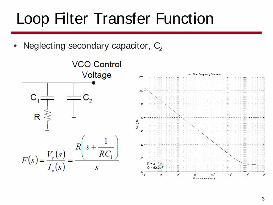
Loop Filter Transfer Function
3
• Neglecting secondary capacitor, C2
Split Proportional & Integral Gain Path
4
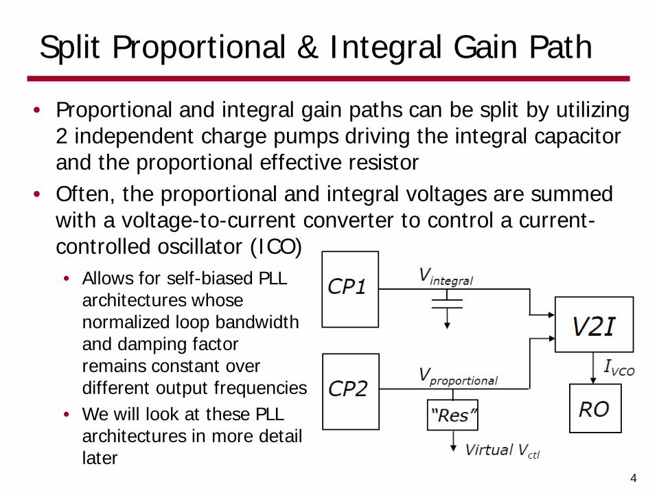
• Proportional and integral gain paths can be split by utilizing 2 independent charge pumps driving the integral capacitor and the proportional effective resistor
• Often, the proportional and integral voltages are summed with a voltage-to-current converter to control a current-controlled oscillator (ICO) • Allows for self-biased PLL
architectures whose normalized loop bandwidth and damping factor remains constant over different output frequencies
• We will look at these PLL architectures in more detail later
Control Voltage Ripple
5
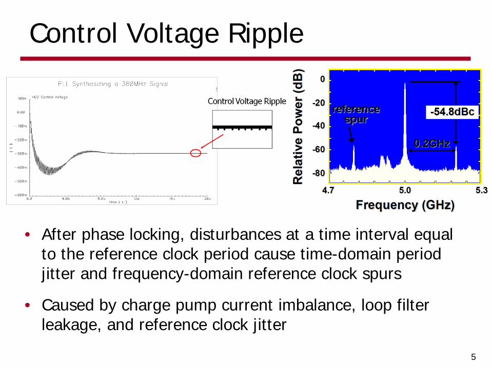
• After phase locking, disturbances at a time interval equal to the reference clock period cause time-domain period jitter and frequency-domain reference clock spurs
• Caused by charge pump current imbalance, loop filter leakage, and reference clock jitter

Pattern Jitter
• A dominant form of pattern jitter is due to the proportional gain term, ICP*R
• Every time the reference clock goes high, charge pump mismatch current dropped on the filter resistor causes control voltage ripple
• This results in shorter output cycles that occur at a time interval equal to the reference clock period
6

Pattern Jitter w/ Secondary Capacitor
• Adding a secondary loop filter capacitor introduces extra filtering, which reduces the control voltage disturbance amplitude, but extends it over many cycles
• Makes the typical ideal second-order PLL into a third-order system
• Stability limits the size of C2
7

PLL w/ Sample-Reset Loop Filter
8
• A PLL with a standard RC filter produces a voltage spike equal to ICP*R for a duration equal to the phase error
• A sample-reset loop filter replaces the resistor with a capacitor that is charged during the phase error and reset every reference cycle
• This spreads the correction voltage nearly uniformly over the entire reference period and reduces the correction voltage peak value
• This eliminates the need for additional filtering with a secondary capacitor, providing the opportunity for near 90° phase margin

Sample-Reset Loop Filter w/ Single Capacitor
9
• A single-capacitor implementation still has a (reduced) ripple component due to the sample, hold, and reset operation
• Also, a very short reset pulse needs to be generated, which may be difficult to realize with the control logic
Sample-Reset Loop Filter w/ Double Capacitors
10
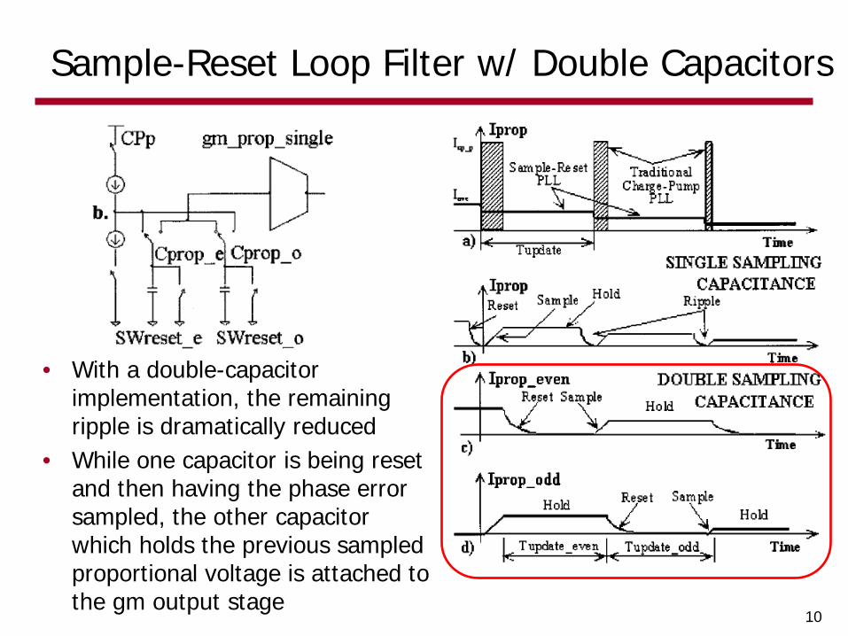
• With a double-capacitor implementation, the remaining ripple is dramatically reduced
• While one capacitor is being reset and then having the phase error sampled, the other capacitor which holds the previous sampled proportional voltage is attached to the gm output stage

Sample-Reset PLL Small-Signal Model
11
( ) ( ) ( )
( )
i
icomiicpmpupdateico
pcp
mi
mpupdate
p
i
icp
pcpico
i
miicp
p
mpupdatepcp
i
miicpproplpf
p
mpupdateprop
i
mi
MCKgI
sgTKI
s
ggT
CC
II
sKCgI
sH
CgTI
sCgI
sIsIsI
CgT
K
sCg
sK
ππ
π
ππ
22
12
22 :Current ICO Total
:Path alProportion
:Path Integral
__2
_
__
__int
int
+
+
+
=
+
=+=
=
=
=
=
==
p
mpupdatepcp
miicp
iico
z
n
mpupdate
mi
i
p
pcp
icpz
i
icomiicpn
CgTI
gMICK
gTg
CC
II
MCKgI
_
_
_
__
221
21
2
πωωζ
ωπ
ω

ICO Control Waveforms
12
• PLL w/ sample-reset filter has dramatically reduced ripple voltage on oscillator control signal
• The control signal displays an almost ideal stair-step response
PLL w/ Sample-Reset Filter Standard Charge Pump PLL
Next Time
• VCOs
13


![ECEN620: Network Theory Broadband Circuit Design Fall 2014 · 2020. 10. 30. · Multiphase Clock Generation ... • Sinusoidal • Linear [Bulzacchelli] [Weinlader] 15. DLL Frequency](https://static.fdocuments.in/doc/165x107/60eb74e02337a65b583b6c1e/ecen620-network-theory-broadband-circuit-design-fall-2014-2020-10-30-multiphase.jpg)