
ECE544: Communication Networks-II, Spring 2007 D. Raychaudhuri Lecture 7 Includes teaching materials...
75
ECE544: Communication Networks-II, Spring 2007 D. Raychaudhuri Lecture 7 Includes teaching materials from L. Peterson
-
date post
20-Dec-2015 -
Category
Documents
-
view
214 -
download
0
Transcript of ECE544: Communication Networks-II, Spring 2007 D. Raychaudhuri Lecture 7 Includes teaching materials...
ECE544: Communication Networks-II, Spring 2007
D. Raychaudhuri
Lecture 7
Includes teaching materials from L. Peterson
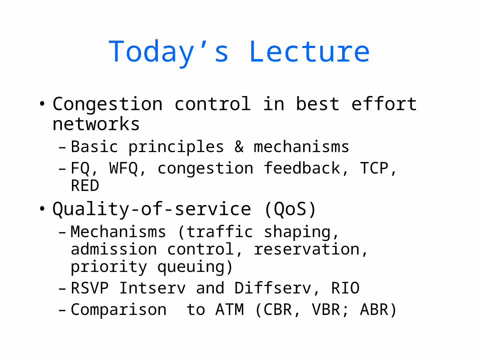
Today’s Lecture
• Congestion control in best effort networks– Basic principles & mechanisms– FQ, WFQ, congestion feedback, TCP, RED
• Quality-of-service (QoS)– Mechanisms (traffic shaping, admission
control, reservation, priority queuing)– RSVP Intserv and Diffserv, RIO– Comparison to ATM (CBR, VBR; ABR)
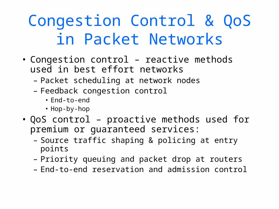
Congestion Control & QoS in Packet Networks
• Congestion control – reactive methods used in best effort networks– Packet scheduling at network nodes– Feedback congestion control
• End-to-end• Hop-by-hop
• QoS control – proactive methods used for premium or guaranteed services:– Source traffic shaping & policing at entry
points– Priority queuing and packet drop at routers– End-to-end reservation and admission control
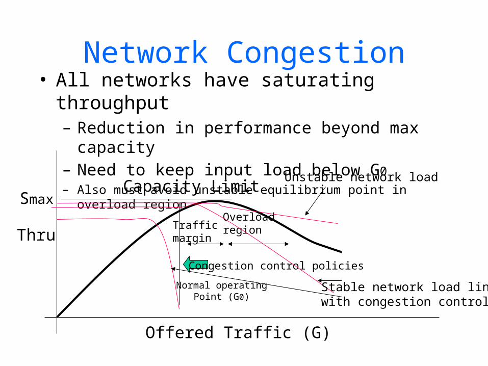
Network Congestion• All networks have saturating throughput
– Reduction in performance beyond max capacity
– Need to keep input load below G0
– Also must avoid unstable equilibrium point in overload region
Overloadregion
Normal operatingPoint (G0)
Capacity LimitSmax
Offered Traffic (G)
ThruTrafficmargin
Congestion control policies
Unstable network load
Stable network load lineswith congestion control

Queue Scheduling
• A queue scheduler employs 2 strategies:– Which packet to serve (transmit) next– Which packet to drop next (when
required)

FIFO Queuing
• FIFO:first-in-first-out (or FCFS: first-come-first-serve)
• Arriving packets get dropped when queue is full regardless of flow or importance - implies drop-tail
• Important distinction:– FIFO: scheduling discipline– Drop-tail: drop policy

Fair Queuing
• Main idea:– maintain a separate queue for each
flow currently flowing through router– router services queues in Round-
Robin fashion

FQ illustrationFlow 1
Flow 2
Flow n
I/P O/P
Variation: Weighted Fair Queuing (WFQ)
Some Complications
• Packets are of different length• We really need bit-by-bit round-
robin• FQ simulates bit-by-bit RR
– Not feasible to interleave bits!
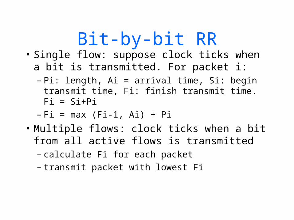
Bit-by-bit RR• Single flow: suppose clock ticks when a bit
is transmitted. For packet i:– Pi: length, Ai = arrival time, Si: begin transmit
time, Fi: finish transmit time. Fi = Si+Pi– Fi = max (Fi-1, Ai) + Pi
• Multiple flows: clock ticks when a bit from all active flows is transmitted– calculate Fi for each packet– transmit packet with lowest Fi

Bit-by-bit RR
Source 1 Source 2
Outbound Link1 unit/sec
Pkt 2-1=3 units
Pkt 1-1=2 units
Pkt 2-2=2 units
Pkt 1-2=1 unit
Pkt 1-3=1 unit
Channel clock - 1
P(1,1) = 2P(1,2) = 1P(1,3) = 1
P(2,1) = 3P(2,2) = 2
Start with A(*,*)=0 (all pkts arrive at T=0)
F(1,1) = 1F(1,2) = 1.5F(1,3) = 2
F(2,1) = 1.5F(2,2) = 2.5
Fi = max (Fi-1, Ai) + Pi
2 3 4 5

Bit-by-bit RR example
F=10
Flow 1(arriving)
Flow 2transmitting
Output
F=2
F=5
F=8
Flow 1 Flow 2 Output
F=10
Cannot preempt packetcurrently being transmitted
Congestion Avoidance
• TCP approach:– Detect congestion after it happens
and back off on offered rate– Increase load trying to maximize
utilization until loss occurs• Alternatively:
– We can try to predict congestion and reduce rate before loss occurs
– This is called congestion avoidance

Congestion Control via Feedback to Source
• TCP’s “blind” approach:– Detect congestion after it happens
and back off on offered rate– Increase load trying to maximize
utilization until loss occurs
SourceRate(bps)
Congestion detected(via packet loss)
Time-out
Pkt losscleared
Additive increaseMultiplicative decrease

Congestion Control via Router Feedback
• Router has unified view of queuing behavior
• Routers can distinguish between propagation and persistent queuing delays
• Routers can decide on transient congestion, based on workload

Solving the Full Queues Problem
• Drop packets before queue becomes full (early drop)
• Intuition: notify senders of incipient congestion– Example: early random drop (ERD):
• If qlen > drop level, drop each new packet with fixed probability p
• Does not control misbehaving users

Random Early Detection (RED)
• Motivation:– High bw-delay flows have large queues
to accommodate transient congestion– TCP detects congestion from loss - after
queues have built up and increase delay
• Aim:– Keep throughput high and delay low– Accommodate bursts
Random Early Detection (RED)
• Detect incipient congestion, allow bursts• Keep power (throughput/delay) high
– keep average queue size low– assume hosts respond to lost packets
• Avoid window synchronization– randomly mark packets
• Avoid bias against bursty traffic• Some protection against ill-behaved users

RED Algorithm
• Maintain running average of queue length
• If avg < minth do nothing– Low queuing, send packets through
• If avg > maxth, drop packet– Protection from misbehaving sources
• Else mark packet in a manner proportional to queue length– Notify sources of incipient congestion
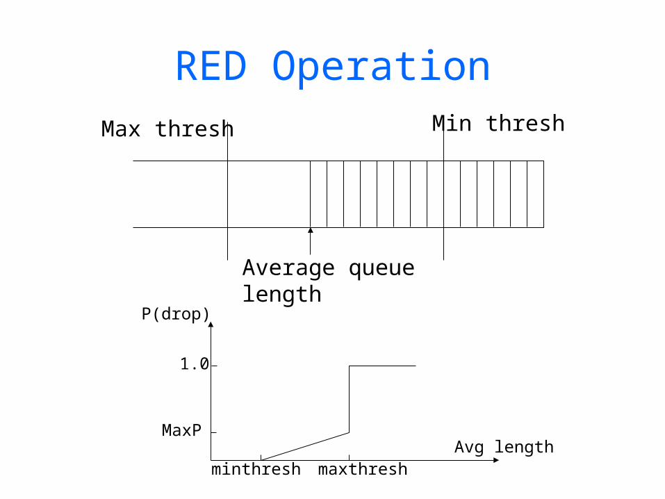
RED OperationMin threshMax thresh
Average queuelength
minthresh maxthresh
MaxP
1.0
Avg length
P(drop)

Quality of Service
OutlineRealtime ApplicationsIntegrated ServicesDifferentiated Services

Realtime Applications• Require “deliver on time” assurances
– must come from inside the network
– Example application (audio)– sample voice once every 125us– each sample has a playback time– packets experience variable delay in network– add constant factor to playback time: playback point
Microphone
Speaker
Sampler,A D
converter
Buffer,D A
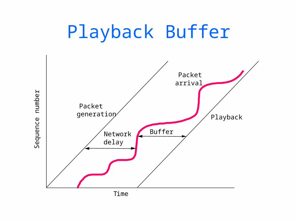
Playback BufferS
eque
nce
num
ber
Packetgeneration
Networkdelay
Buffer
Playback
Time
Packetarrival

Example Distribution of Delays
1
2
3
Pa
cke
ts (
%)
90% 97% 98% 99%
150 20010050
Delay (milliseconds)
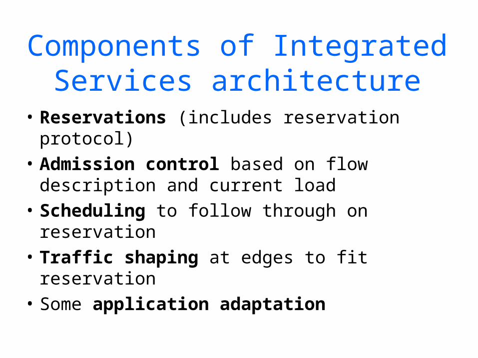
Components of Integrated Services architecture
• Reservations (includes reservation protocol)
• Admission control based on flow description and current load
• Scheduling to follow through on reservation
• Traffic shaping at edges to fit reservation• Some application adaptation
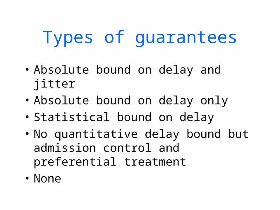
Types of guarantees
• Absolute bound on delay and jitter• Absolute bound on delay only• Statistical bound on delay• No quantitative delay bound but
admission control and preferential treatment
• None

Internet service classes proposed by IETF
• Guaranteed service– firm bounds on e2e delays and bandwidth
• Controlled load– “a QoS closely approximating the QoS that
same flow would receive from an unloaded network element, but uses capacity (admission) control to assure that this service is received even when the network element is overloaded”
• Best effort

Taxonomy of applications
Applications
ElasticReal-Time
Loss, delay tolerant
IntolerantInteractive
Non-adaptiveadaptive Non-adaptive
Delayadaptive
Rateadaptive
Rateadaptive
Asynchronous
Interactive-bulk

Statistical multiplexing
• Share output link among many sources• Strong law of large numbers:
– Given large set of uncorrelated flows, total BW required nearly constant even if individual flows vary a lot
– Intuition: if many flows, then each is small compared to aggregate and bursts come at different times
– if correlated, bursts come at same time

Self-similarity
• Problem: self-similarity persists at all levels
• Burstiness even for aggregates• Heavy-tailed distributions at all
aggregations

Utility curve shapes
BW
U
BW
U
BW
U Stay to the right and youare fine for all curves
Elastic Hard real-time
Delay-adaptive
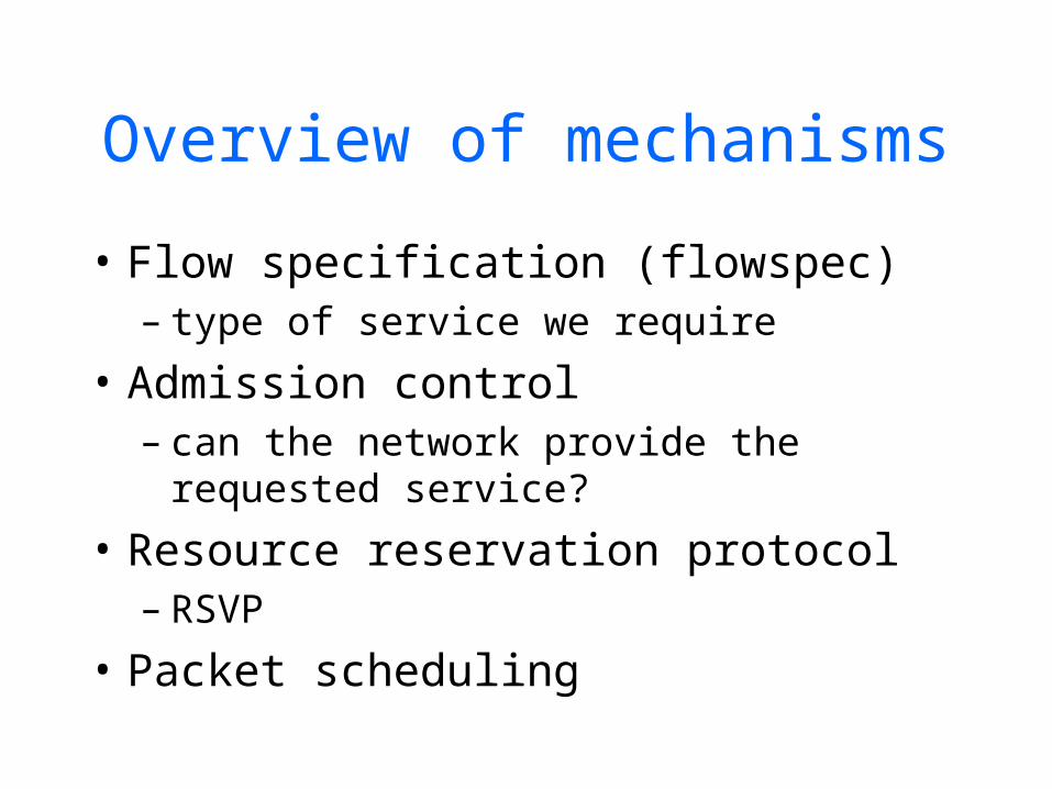
Overview of mechanisms
• Flow specification (flowspec)– type of service we require
• Admission control– can the network provide the requested
service?
• Resource reservation protocol– RSVP
• Packet scheduling
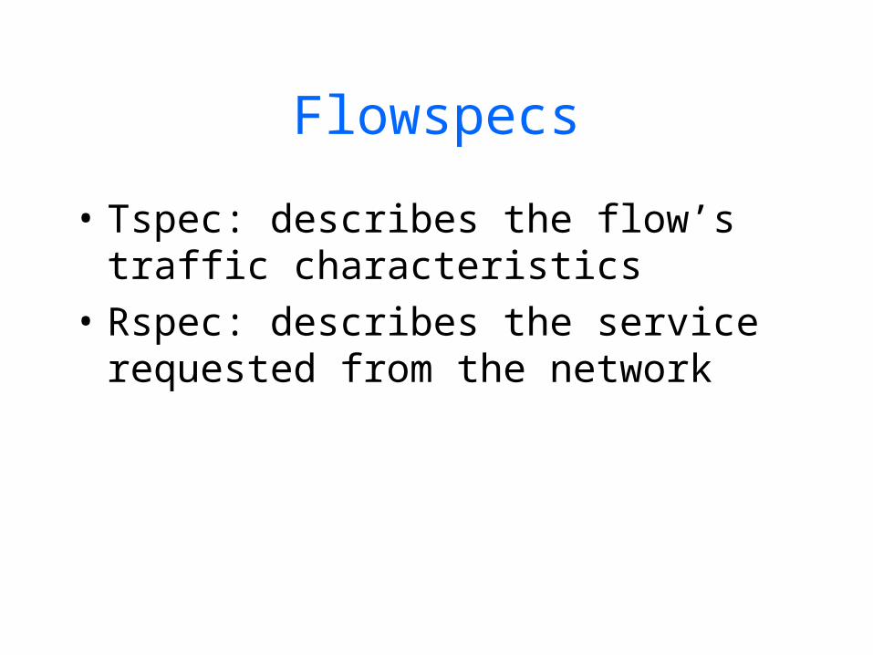
Flowspecs
• Tspec: describes the flow’s traffic characteristics
• Rspec: describes the service requested from the network

Token bucket filter• Described by 2 parameters:
– token rate r: rate of tokens placed in the bucket– bucket depth B: capacity of the bucket
• Operation:– tokens are placed in bucket at rate r– if bucket fills, tokens are discarded– sending a packet of size P uses P tokens– if bucket has P tokens, packet sent at max rate,
else must wait for tokens to accumulate
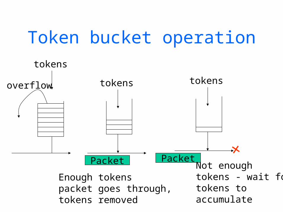
Token bucket operation
tokens
Packet
overflow
tokens
tokens
Packet
Enough tokenspacket goes through,tokens removed
Not enoughtokens - wait fortokens toaccumulate
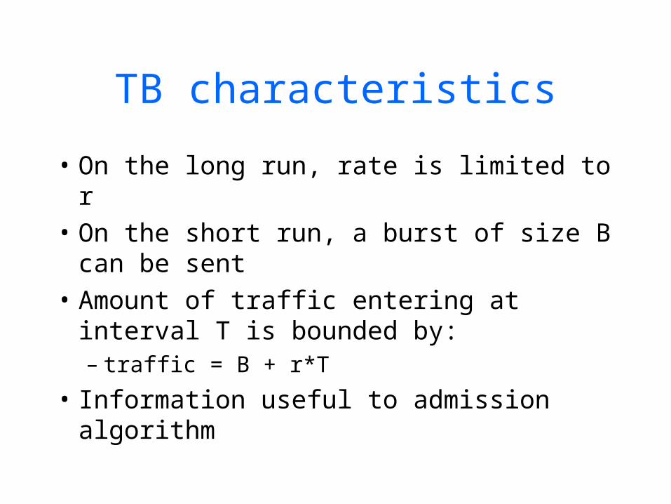
TB characteristics
• On the long run, rate is limited to r• On the short run, a burst of size B
can be sent• Amount of traffic entering at
interval T is bounded by:– traffic = B + r*T
• Information useful to admission algorithm

Token bucket specs
BW
Time
1
2
1 2 3
Flow A
Flow BFlow A: r = 1 Mbps, B=1 byte
Flow B: r = 1 Mbps, B=1MB

Admission control
• When new flow, look at Rspec and Tspec and decide whether to admit or reject
• Not policing

Parekh bound on delay across net
Di = (bucket size/weighted rate allocated) + [(nhops - 1) * MaxPacketLen / weighted rate allocation] + m=1 to hopi (max packet length / outbound bw at hop)– 1st term: delay when running at full speed– 2nd term: packetization effects– 3rd term: added delay due to packet approx
of FQ (goes away as data rate increases)
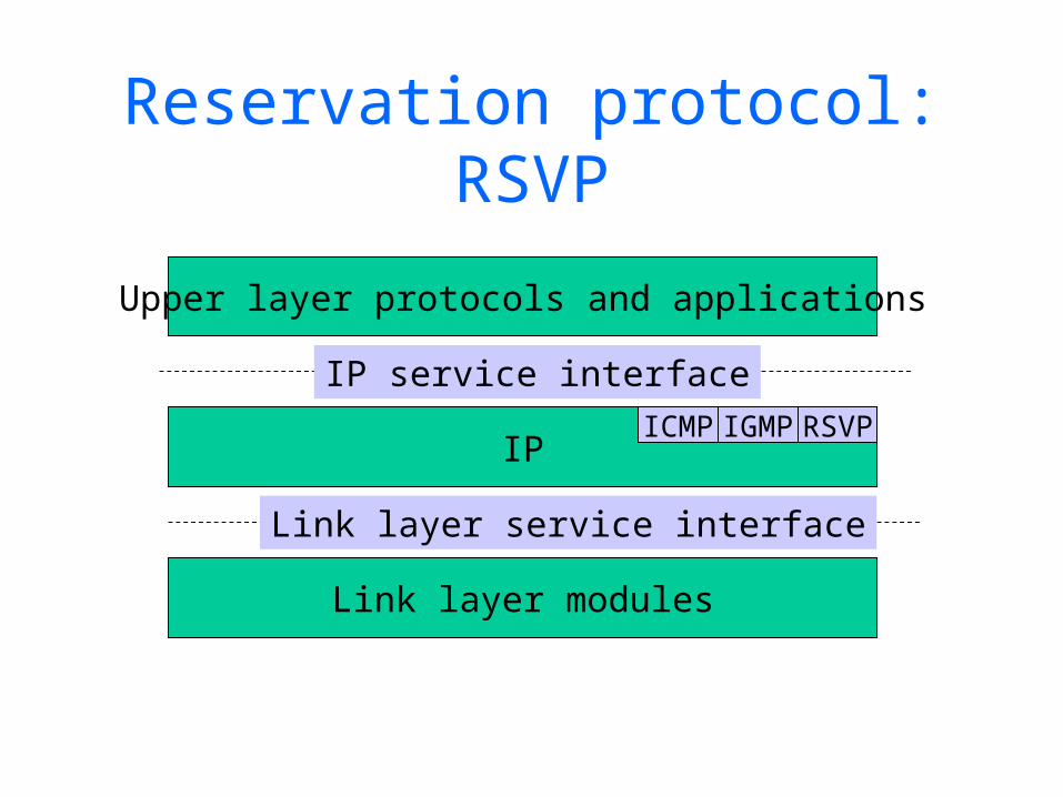
Reservation protocol: RSVP
Upper layer protocols and applications
IP
Link layer modules
ICMP IGMP RSVP
IP service interface
Link layer service interface
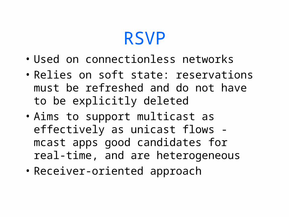
RSVP• Used on connectionless networks• Relies on soft state: reservations must
be refreshed and do not have to be explicitly deleted
• Aims to support multicast as effectively as unicast flows - mcast apps good candidates for real-time, and are heterogeneous
• Receiver-oriented approach

Role of RSVP
• Rides on top of unicast/multicast routing protocols
• Carries resource requests all the way through the network
• At each hop consults admission control and sets up reservation. Informs requester if failure
• RSVP only carries messages

Changing reservation
• Receiver-oriented approach and soft state make it easy to modify reservation
• Modification sent with periodic refresh
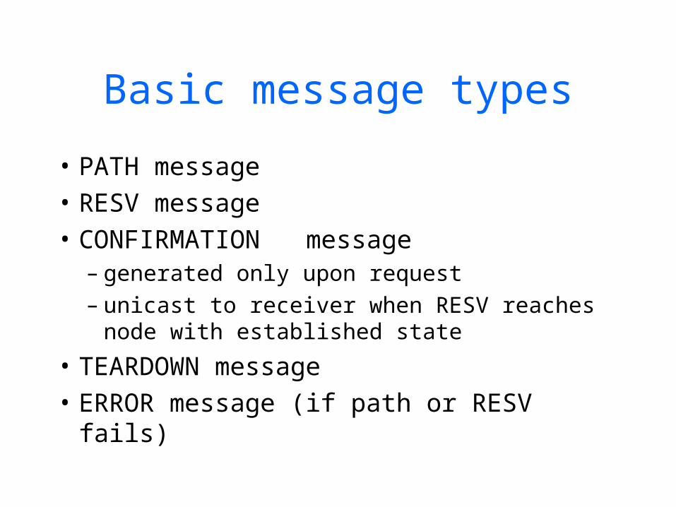
Basic message types
• PATH message• RESV message• CONFIRMATION message
– generated only upon request– unicast to receiver when RESV reaches
node with established state
• TEARDOWN message• ERROR message (if path or RESV fails)

Making a reservation
• Receivers make reservation• Before making a reservation,
receiver must know:– type of traffic sender will send (Tspec)– path the sender’s packets will follow
• Both can be accomplished by sending PATH messages

PATH messages• PATH messages carry sender’s Tspec• Routers note the direction PATH
messages arrived and set up reverse path to sender
• Receivers send RESV messages that follow reverse path and setup reservations
• If reservation cannot be made, user gets an error

PATH and RESV messages
R
Sender 1
Sender 2
receiver 1
receiver 2
R R
R
PATH
PATH RESV
RESV
RESV (merged)
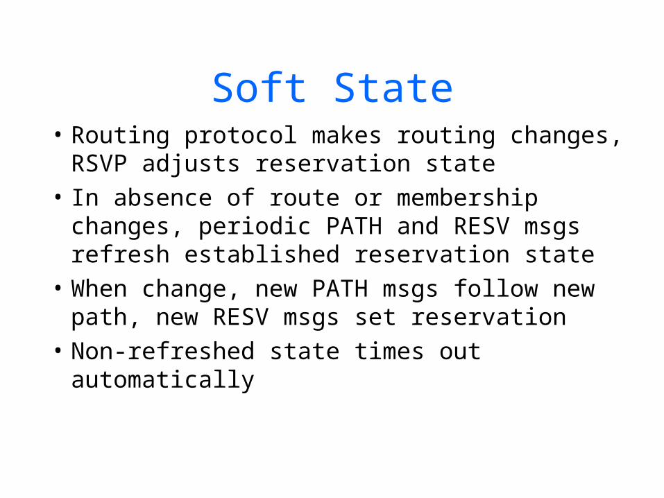
Soft State• Routing protocol makes routing changes,
RSVP adjusts reservation state• In absence of route or membership
changes, periodic PATH and RESV msgs refresh established reservation state
• When change, new PATH msgs follow new path, new RESV msgs set reservation
• Non-refreshed state times out automatically
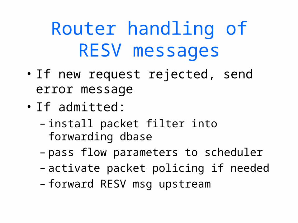
Router handling of RESV messages
• If new request rejected, send error message
• If admitted:– install packet filter into forwarding
dbase– pass flow parameters to scheduler– activate packet policing if needed– forward RESV msg upstream
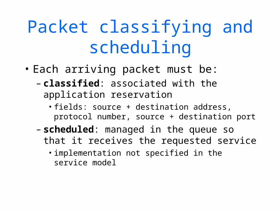
Packet classifying and scheduling
• Each arriving packet must be:– classified: associated with the
application reservation• fields: source + destination address,
protocol number, source + destination port
– scheduled: managed in the queue so that it receives the requested service• implementation not specified in the service
model

RSVP and multicast
• Reservations from multiple receivers for a single sender are merged together at branching points
• Reservations for multiple senders may not be added up:– audio conference, not many talk at same
time– only subset of speakers (filters)– mixers and translators
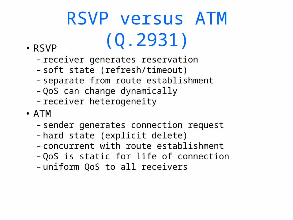
RSVP versus ATM (Q.2931)• RSVP
– receiver generates reservation– soft state (refresh/timeout)– separate from route establishment– QoS can change dynamically– receiver heterogeneity
• ATM– sender generates connection request– hard state (explicit delete)– concurrent with route establishment– QoS is static for life of connection– uniform QoS to all receivers
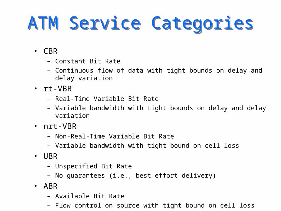
ATM Service CategoriesATM Service Categories
• CBR– Constant Bit Rate– Continuous flow of data with tight bounds on delay and delay
variation
• rt-VBR– Real-Time Variable Bit Rate– Variable bandwidth with tight bounds on delay and delay
variation
• nrt-VBR– Non-Real-Time Variable Bit Rate– Variable bandwidth with tight bound on cell loss
• UBR– Unspecified Bit Rate– No guarantees (i.e., best effort delivery)
• ABR– Available Bit Rate– Flow control on source with tight bound on cell loss

Traffic ManagementTraffic Management
• Problem: Providing quality of service– How should ATM network resources be allocated to
ensure good performance including preventing congestion, e.g., how many virtual channels should be assigned to a particular transmission link?
• Solution: Traffic Management– Specify the traffic "contract" on each virtual
channel/path– Route (including rejecting setup request) each virtual
channel/path along a path with adequate resources (Admission Control)
– Mark (via Cell Loss Priority bit) for loss all cells that violate the contract (Traffic Policing)
77 66 55 44 33 22 11 00
Generic Flow Generic Flow ControlControl
Virtual Path Virtual Path IdentifierIdentifier
Virtual Path Virtual Path IdentifierIdentifier
Virtual Channel Virtual Channel IdentifierIdentifier
Virtual ChannelVirtual ChannelIdentifierIdentifier
CLPCLP
Header ErrorHeader ErrorCheckCheck
PayloadPayload(48 bytes)(48 bytes)
Virtual Channel Virtual Channel IdentifierIdentifier
Payload Type Payload Type IdentifierIdentifier

Generic Cell Rate Algorithm
Generic Cell Rate Algorithm
• For a sequence of cell arrival times, {tk}, determines which cells conform to the traffic contract
• A counter scheme based on two parameters denoted GCRA(I,L)– Increment parameter: I
• affects cell rate
– Limit parameter: L• affects cell bursts
• “Leaky bucket”– A cell that would cause the bucket to
overflow is non-conforming
One unit leak One unit leak per unit of timeper unit of time
I for each cell I for each cell arrivalarrival
L + IL + I
77 66 55 44 33 22 11 00
Generic Flow Generic Flow ControlControl
Virtual Path Virtual Path IdentifierIdentifier
Virtual Path Virtual Path IdentifierIdentifier
Virtual Channel Virtual Channel IdentifierIdentifier
Virtual ChannelVirtual ChannelIdentifierIdentifier
CLPCLP
Header ErrorHeader ErrorCheckCheck
PayloadPayload(48 bytes)(48 bytes)
Virtual Channel Virtual Channel IdentifierIdentifier
Payload Type Payload Type IdentifierIdentifier

Smooth TrafficSmooth Traffic
CellCell CellCell NoNoCellCell
Bucket fill just before and just after cell transmit timeBucket fill just before and just after cell transmit time
GCRA(1.5, .5)GCRA(1.5, .5)
t+t+t-t-
11
22
t+t+t-t-
11
22
t+t+t-t-
11
22
t+t+t-t-
11
22
CellCell CellCell
t+t+t-t-
11
22
timetime
77 66 55 44 33 22 11 00
Generic Flow Generic Flow ControlControl
Virtual Path Virtual Path IdentifierIdentifier
Virtual Path Virtual Path IdentifierIdentifier
Virtual Channel Virtual Channel IdentifierIdentifier
Virtual ChannelVirtual ChannelIdentifierIdentifier
CLPCLP
Header ErrorHeader ErrorCheckCheck
PayloadPayload(48 bytes)(48 bytes)
Virtual Channel Virtual Channel IdentifierIdentifier
Payload Type Payload Type IdentifierIdentifier
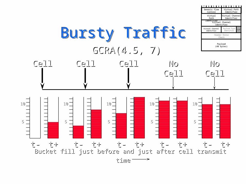
Bursty TrafficBursty Traffic
55
1010
t+t+t-t-
55
1010
t+t+t-t-
55
1010
t+t+t-t-
55
1010
t+t+t-t-
55
1010
t+t+t-t-
CellCell CellCell CellCell NoNoCellCell
NoNoCellCell
Bucket fill just before and just after cell transmit Bucket fill just before and just after cell transmit
GCRA(4.5, 7)GCRA(4.5, 7)
timetime
77 66 55 44 33 22 11 00
Generic Flow Generic Flow ControlControl
Virtual Path Virtual Path IdentifierIdentifier
Virtual Path Virtual Path IdentifierIdentifier
Virtual Channel Virtual Channel IdentifierIdentifier
Virtual ChannelVirtual ChannelIdentifierIdentifier
CLPCLP
Header ErrorHeader ErrorCheckCheck
PayloadPayload(48 bytes)(48 bytes)
Virtual Channel Virtual Channel IdentifierIdentifier
Payload Type Payload Type IdentifierIdentifier

Payload Type IdentifierPayload Type Identifier• Bit 3: Used to discriminate data cells
from operation, administration, maintenance cells.
• Bit 2: Used to indicate congestion in data cells (Bit 3 = 0)– Set by Switches– Source and Destination Behavior Defined for
Available Bit Rate Flow Control VCC’s
• Bit 1: Carried transparently end-to-end in data cells– Used by AAL5
Payload Type Payload Type IdentifierIdentifier
77 66 55 44 33 22 11 00
Generic Flow Generic Flow ControlControl
Virtual Path Virtual Path IdentifierIdentifier
Virtual Path Virtual Path IdentifierIdentifier
Virtual Channel Virtual Channel IdentifierIdentifier
Virtual ChannelVirtual ChannelIdentifierIdentifier
CLPCLP
Header ErrorHeader ErrorCheckCheck
PayloadPayload(48 bytes)(48 bytes)
Virtual Channel Virtual Channel IdentifierIdentifier
CC

SourceSource DestinationDestination
++ ++ ++Forward RM* CellsForward RM* Cells
CongestionCongestionIndicationIndication
++ ++RateRate
IndicationIndicationRate & CongestionRate & Congestion
IndicationIndication
*- Resource Management*- Resource Management
Backward RM* CellsBackward RM* Cells
B
ABR Feedback
• Source sets Actual Cell Rate Source sets Actual Cell Rate based on rate & congestion based on rate & congestion feedbackfeedback
Payload Type Payload Type IdentifierIdentifier
77 66 55 44 33 22 11 00
Generic Flow Generic Flow ControlControl
Virtual Path Virtual Path IdentifierIdentifier
Virtual Path Virtual Path IdentifierIdentifier
Virtual Channel Virtual Channel IdentifierIdentifier
Virtual ChannelVirtual ChannelIdentifierIdentifier
CLPCLP
Header ErrorHeader ErrorCheckCheck
PayloadPayload(48 bytes)(48 bytes)
Virtual Channel Virtual Channel IdentifierIdentifier
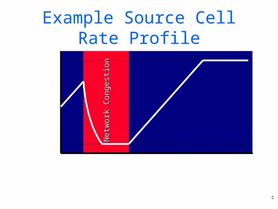
Example Source Cell Rate Profile
PeakCell Rate
MinimumCell Rate
Act
ual
Cell
Rate
Time
Netw
ork
Con
gest
ion
Netw
ork
Con
gest
ion
C
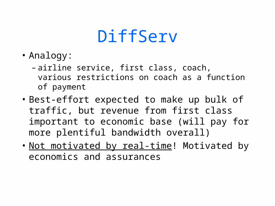
DiffServ• Analogy:
– airline service, first class, coach, various restrictions on coach as a function of payment
• Best-effort expected to make up bulk of traffic, but revenue from first class important to economic base (will pay for more plentiful bandwidth overall)
• Not motivated by real-time! Motivated by economics and assurances

Types of service• Premium service: (type P)
– admitted based on peak rate– conservative, virtual wire services– unused premium goes to best effort
(subsidy!)
• Assured service: (type A)– based on expected capacity usage profiles– traffic unlikely to be dropped if user maintains
profile. Out-of-profile traffic marked

Differences with RSVP
• No need for reservations: just mark packets
• Packet marking can be done at administrative boundaries before injecting packets into network
• Significant savings in signaling, much simpler overall
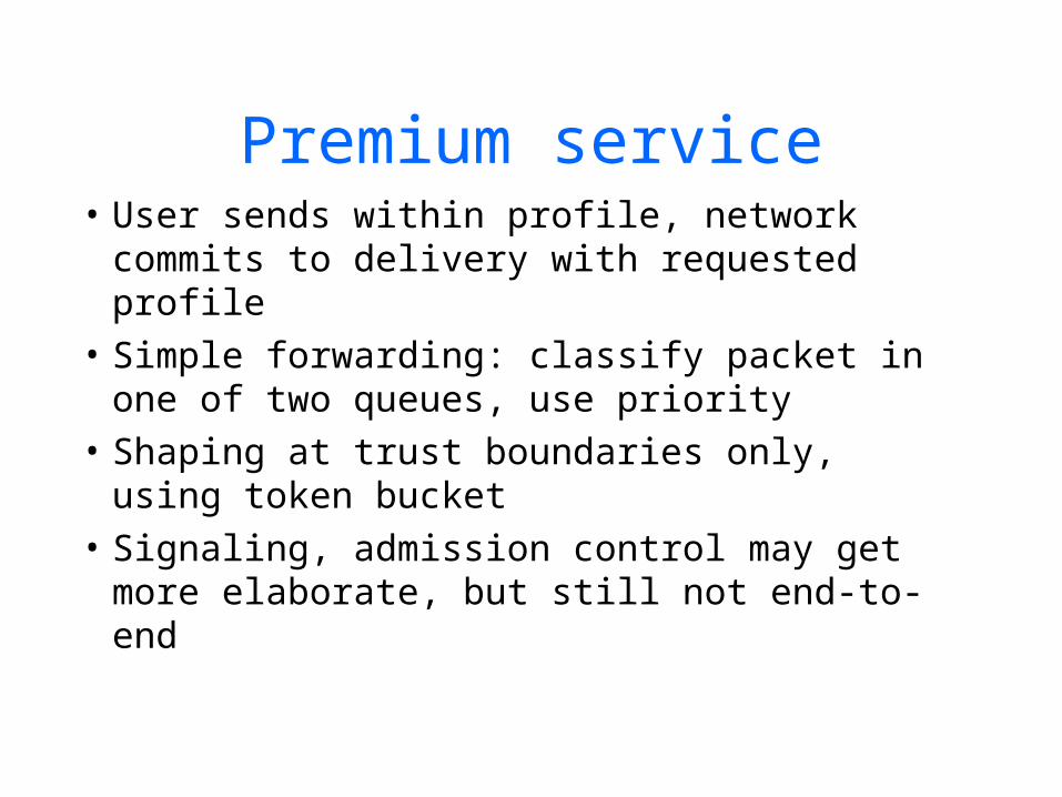
Premium service• User sends within profile, network
commits to delivery with requested profile
• Simple forwarding: classify packet in one of two queues, use priority
• Shaping at trust boundaries only, using token bucket
• Signaling, admission control may get more elaborate, but still not end-to-end

Premium traffic flow
first hoprouter
internalrouter
borderrouter
host
borderrouter
ISP
Company A
Unmarkedpacket flow
Packets in premiumflows have bit set
Premium packet flowrestricted to R bytes/sec

2-bit differentiated service
• Precedence field encodes P & A type packets
• P packets are queued at higher priority than ordinary best effort
• A packets treated preferentially wrt dropping probability in the normal queue
• Leaf and border routers have input and output tasks - other routers just output

Leaf router input functionality
ClearA & P
bits
Packetclassifier
Marker 1
Marker N
Forwardingengine
Arrivingpacket Best effort
Flow
1Fl
ow N
Markers: service class, rate, permissible burst size
Marker function in routers
• Leaf routers have traffic profiles - they classify packets based on packet header
• If no profile present, pass as best effort• If profile is for A:
– mark in-profile packets with A, forward others unmarked
• If profile is for P:– delay out-of -profile packets to shape into
profile

Markers to implement two different services
Wait fortoken
Set P bitPacketinput
Packetoutput
Test iftoken Set A bit
token
No token
Packetinput
Packetoutput
Drop on overflow
Output forwarding
• 2 queues: P packets on higher priority queue
• Lower priority queue implements RED “In or Out” scheme (RIO)
• At border routers profile meters test marked flows:– drop P packets out of profile– unmark A packets
Router output interface for two-bit architecture
P-bit set?
If A-bit setincr A_cnt
High-priority Q
Low-priority Q
If A-bit setdecr A_cnt
RIO queuemanagement
Packets out
yes
no

Border router input interface Profile Meters
Arrivingpacket
Is packetmarked?
Tokenavailable?
Tokenavailable?
Clear A-bit
Drop packet
Forwardingengine
A set
P set
token
token
Not marked
no
no

Red with In or Out (RIO)• Similar to RED, but with two separate
probability curves• Has two classes, “In” and “Out” (of
profile)• “Out” class has lower Minthresh, so
packets are dropped from this class first• As avg queue length increases, “in”
packets are dropped

RIO drop probabilities
MaxP
1.0
Minout Minin MaxinMaxout
P(drop)
AvgLen

75
Today’s Homework• Peterson & Davie, Chap 4,6
-6.13-6.32-6.43-6.44-6.45
Download and browse RSVP & DiffServe RFC’s