Chapter 10 Bresenham’s Algorithm Data Structures and Graphics or Working with Models.
Upload
hoangnguyetCategory
view
219download
0
ECE532 Project Group ReportMD Simulation Performance Acceleration based MPI on FPGA Platform
Hao Jun Liu, Chao [email protected], [email protected]
1 Project Overview
1.1 Goals
The first goal of our project is to develop an MD(Molecule Dynamic) simulation engine on FPGA. Thesecond goal is to add MPI as the synchronization protocol so that it is possible to run multiple simulationengines on FPGA. The ultimate goal is to measure the performance of the simulation engines and pin pointthe performance bottlenecks so that improvement of the engine can be made.
1.2 Project Background
MD simulation is a simulation technique that calculates atoms’ positions based on the forces between them.The algorithm we have is implemented in C++ and we used ImpulseC compiler to compile the C++ codeinto VHDL. ImpulseC is a subset of C with additional libraries provided. The Impulse C code used in ourdesign is hand written based on the C++ code we have. The ultimate goal is to use a cluster of FPGAs torun MD simulation faster compared with regular high performance machines with lower power.
1.3 System Block Diagram
Fig. 1 is the current block diagram of the simulation core.
Figure 1: System Block Diagram
1
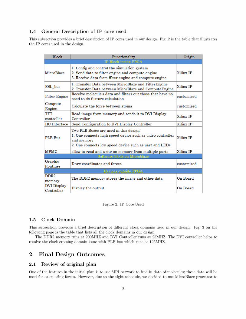
1.4 General Description of IP core used
This subsection provides a brief description of IP cores used in our design. Fig. 2 is the table that illustratesthe IP cores used in the design.
Figure 2: IP Core Used
1.5 Clock Domain
This subsection provides a brief description of different clock domains used in our design. Fig. 3 on thefollowing page is the table that lists all the clock domains in our design.
The DDR2 memory runs at 200MHZ and DVI Controller runs at 25MHZ. The DVI controller helps toresolve the clock crossing domain issue with PLB bus which runs at 125MHZ.
2 Final Design Outcomes
2.1 Review of original plan
One of the features in the initial plan is to use MPI network to feed in data of molecules; these data will beused for calculating forces. However, due to the tight schedule, we decided to use MicroBlace processor to
2

Figure 3: Clock Domain
transfer the data to hardware cores via FSL bus.Another important change in the project is to reduce the number of floating points calculation in the
FilterEngine block and ComputeEngine block. This is because the float point calculation consumes over300 DSP cores on FPGA. The FPGA we have contains only 64 DSP cores. The total number of requiredDSP cores exceeds the number available on the FPGA. Therefore we decided to reduce some floating pointscalculation that are not critical in the design.
2.2 Final Design
We have successfully build a system that is capable of performing MD simulation. The FilterEngine blockcan receive input data of molecules, send out desirable ones via FSL bus and discard the rest. The Com-puteEngine block can receive data from the FilterEngine block and calculate forces between molecules. Bothblocks are customized and implemented in hardware. Finally the result forces can be plotted on the monitorusing DVI controller. The drawing function is implemented in software running on MicroBlaze processor.The requirement of this project is to have at least one processor and have at least one customized core inthe design. We have successfully accomplished that.
In order to achieve better performance, our design requires significant improvememnts and this will bediscussed in section 4.
3 Description of IP Blocks
3.1 MicroBlaze Processor
MicroBlaze is a built-in soft processor that is provided as part of the EDK.[5] The processor is added intothe design through Xilinx EDK project wizard.[1] The processor has the following two functions:
• MicroBlaze contains the instructions for writing and read to and from system memory and FSL bus.
• A software program is running on the MicroBlaze which controls the entire system.
3.2 FSL Bus
FSL (Fast Simplex Link) bus is provided in the Xilinx IP catalog named as FSL V20. The FSL bus is auni-directional point-point FIFO-based communication channel bus. It is mainly used for transfering datafrom register file on the MicroBlaze processor to FilterEngine Block and ComputeEngine Block.[2]
3.3 Filter Engine Block
Filter Engine Block is a fully customized block. One molecule is surrounded by multiple molecules. Onlymolecules nearby contribute significant forces. Hence the function of this block is to determine whichmolecules are necessary for calculating forces. This block receives positions of molecules from MicroBlazeand writes back to MicroBlaze via FSL bus.
3

The Filter Engine is designed by first writing Impulse C code that is supported by the ImpulseC compiler.The compiler then generates HDL that can be used as an IP core in EDK. Two levels of simulations areperformed to ensure the functionality of the core. The first one is a software level simulation performed bythe CoDeveloper Application Manager, Fig. 4 gives an example of software simulation of the Filter Engine.We did another level of simulation, the behavioral simulation. Fig. 5 on the following page gives an exampleof behavioral simulation using Modelsim.
Figure 4: Filter Engine Application Manager Simulation
3.4 Compute Engine Block
ComputerEngine Block is another fully customized hardware block. The function of this block is to calculateforces between molecules. This block receives data produced by the FilterEngine block from MicroBlaze andwrites back to MicroBlaze via FSL bus.
The Compute Engine is designed in the same way as the Filter Engine. Fig. 6 on page 6 gives an exampleof behavioral simulation using Modelsim.
3.5 DVI controller Block
DVI(Digital Visual Interface) controller is provided in the Xilinx IP catalog. The DVI controller reads datafrom a video buffer and displays the image on screen.[3]
3.6 Software Program
The software is capable of plotting coordinates and lines on the screen based on Bresenham’s line algorithm.This program is running on MicroBlaze Processor.
4 Design Methodology
4.1 Impulse CoDeveloper
The customized blocks Filter Engine and Compute Engine are generated by impulse C software-to-hardwarecompiler.[5] This compiler is included in the Impulse CoDeveloper. In the design process, we used this tool tocompile impulse C code to VHDL code. It has been demonstrated that the generated VHDL code is reliableand also is synthesizable by Xilinx ISE. By using this tool, the IP core design time is reduced significantly.
Here is a list of advantages and disadvantages or space of improvement of the Impulse CoDeveloperAdvantages:
• Much lower hardware development time if the designers understand the limitation of this compiler
4

Figure 5: Filter Engine Modelsim Simulation
• Easier to add functionality into a hardware block
Disadvantages:
• A long learning process of the limitations of this tool
• No widely available technical support and discussion forum
• Programming Model does not support external memory via PLB bus
4.2 Future improvement and suggestion
Our Project is only a preliminary step in developing an MD simulator running on FPGA using MPI protocol.First, the MPI protocol is not added in at this point due to the tight schedule. Second, mapping the entiresoftware algorithm is almost impossible on FPGA. The chip area is not large enough to hold all the functions.Moreover, the traditional memory model used in software does not works well in hardware. To make thingseven worse, control flow instructions can dramatically reduce area efficiency thus reduce overall systemperformance. Therefore, new programming paradigm in designing accelerators on FPGAs has to be devised.
Since Hao Jun is going to continue on this project with Prof. Chow during the summer, he could improvethe design in the following aspects:
5

Figure 6: Compute Engine Modelsim Simulation
• implement a better algorithm to perform MD simulation on hardware with low number of DSP cores
• use MPI as the coherence protocol
• implement multiple hardware computing engines to improve the performance of the design
6
APPENDIX
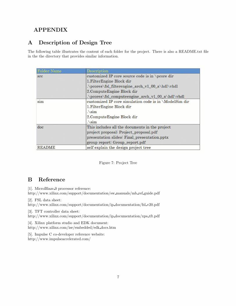
A Description of Design Tree
The following table illustrates the content of each folder for the project. There is also a README.txt filein the the directory that provides similar information.
Figure 7: Project Tree
B Reference
[1]. MicroBlaze 0 processor reference:http://www.xilinx.com/support/documentation/sw manuals/mb ref guide.pdf
[2]. FSL data sheet:http://www.xilinx.com/support/documentation/ip documentation/fsl v20.pdf
[3]. TFT controller data sheet:http://www.xilinx.com/support/documentation/ip documentation/xps tft.pdf
[4]. Xilinx platform studio and EDK document:http://www.xilinx.com/ise/embedded/edk docs.htm
[5]. Impulse C co-developer reference website:http://www.impulseaccelerated.com/
7
![INDEX []€¦ · EX NO: 2 BRESENHAM’S CIRCLE DRAWING ALGORITHM DATE: Aim : To write a C program to draw a Circle using Bresenham’s Algorithm. Algorithm: Step 1: Start the program.](https://static.fdocuments.in/doc/165x107/5f2ae2d3e86b0e70b5516c9a/index-ex-no-2-bresenhamas-circle-drawing-algorithm-date-aim-to-write-a.jpg)