ECE442 Communications Lecture 3. Modulation...
37
ECE442 Communications Lecture 3. Modulation and Demodulation Husheng Li Dept. of Electrical Engineering and Computer Science Fall, 2013
Transcript of ECE442 Communications Lecture 3. Modulation...

ECE442 CommunicationsLecture 3. Modulation and Demodulation
Husheng Li
Dept. of Electrical Engineering and Computer Science
Fall, 2013

Purpose of Modulation and De-modulation
1 Modulation: mapping coded bits into base band signal.2 Demodulation: recover the coded bits from received base
band signal.3 Requirement:
High spectral efficiency (use as small bandwidth aspossible)High power efficiency (use as small power as possible)High reliability (demodulation error being as small aspossible)
4 Analysis tool: theory of detection.

Some History
In the mid-1870s, a form of amplitude modulation, initially called"undulatory currents", was the first method to successfullyproduce quality audio over telephone lines. In early 1900s,Reginald Fessenden demonstrated AM in audio.
Frequency modulation was proposed by Edwin Armstrong in hispaper "A Method of Reducing Disturbances in Radio Signalingby a System of Frequency Modulation" in 1935.

Signal and System Model
A signal can usually be written as
si (t) =N∑
j=1
sijφj (t),
where φj (t) is the j-th basis function.

Signal Space and Representation
For linear modulation (amplitude or phase modulation), thesignal space is a two-dimensional vector space. The basevectors are φ1(t) = cos(2πfc t) and φ2(t) = sin(2πfc t).
The representation of signal in the vector space is calledconstellation.

Receiver Structure
We can use integrator to obtain rj =∫ T
0 r(t)φj (t)dt and the vectorr = (r1, ..., rN) is called the sufficient statistics.

Signal Projection
The noise should not help the detection since its projection ontothe signal space is zero.

Decision Regions
Decision rules are represented by decision regions (decision i ifthe received signal falls r in region Zi ).
Error probability (suppose M equal probably messages)
Pe =1M
M∑m=1
P(r not in Zm|message m).

Maximum Likelihood Receiver
Given a received signal r , define the likelihood of the j-thpossible signal as
L(sj) = p(r |sj).
When the noise is Gaussian, the log-likelihood is given byl(sj) = − 1
N0‖r − si‖2.
The maximum likelihood receiver outputs the messagecorresponding to the signal maximizes the likelihood(log-likelihood).

Matched Filter
We call a filter with impulse response ψ(t) = φ(T − t) thematched filter of signal φ(t).The maximum likelihood receiver can also be implementedusing the matched filter.

Error Probability
The error probability is given by
Pe = 1− 1M
M∑i=1
∫Zi−si
p(n)dn.

Union Bound
The error probability is upper bounded by
Pe =M∑
i=1
p(mi)Pe(mi sent) ≤ 1M
M∑i=1
M∑k=1,k 6=i
Q(
dik√2N0
).
The approximation of the error can be obtained by
Pe ≈ MddimQ(
dmin
2N0
).

Passband Modulation Principles
The modulated signal can be written as
s(t) = a(t) cos[2π(fc + f (t))t + θ(t) + φ0].
In the form of in-phase and quadrature components, wehave
s(t) = sI(t)cos(2πfc t)− sQ(t)sin(2πfc t),
which can also be written as the complex basebandrepresentation: s(t) = R
[u(t)e2πfc t].

Amplitude and Phase Modulation
Information can be carried in (M is the size of constellation)
Amplitude only: MAPM (PAM: pulse amplitude modulation);Phase only: MPSK (PSK: phase shift keying)Both amplitude and phase: MQAM (QAM: quadratureamplitude modulation)
MPAM, MPSK and MQAM are all linear modulations.

M-PAM
Information can be carried in (M is the size of constellation)
Amplitude only: MAPM (PAM: pulse amplitude modulation);Phase only: MPSK (PSK: phase shift keying)Both amplitude and phase: MQAM (QAM: quadratureamplitude modulation)
MPAM, MPSK and MQAM are all linear modulations.

Structure of M-QAM Transmitter

Homework 3
Problem 1. Suppose that the pulse shape g(t) =√
2/Ts(Ts is the symbol period). The minimum distance in theconstellation is d . Find the average energy of 8PAM and16QAM.Problem 2. Consider a channel with Doppler spreadBd = 50Hz. Then, what time separation is required insamples of the received signal such that the samples areapproximately independent?Problem 3. Consider 16QAM. Find an upper bound and anapproximation of the demodulation error rate is
d min√2N0
= 10dB.
Deadline: Sept. 23rd, 2013.
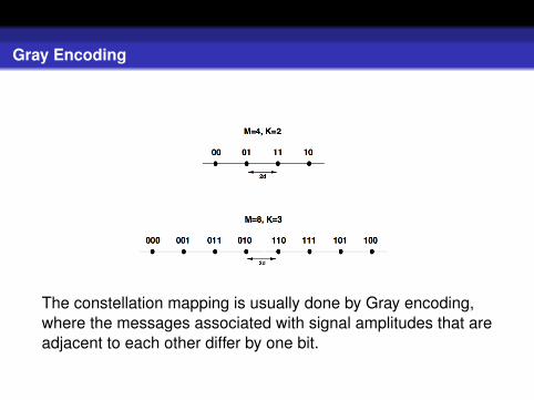
Gray Encoding
The constellation mapping is usually done by Gray encoding,where the messages associated with signal amplitudes that areadjacent to each other differ by one bit.

Phase Shift Keying (MPSK)
In MPSK, the information is encoded in the phase:
si(t) = Ag(t)cos[2πfc t +
2π(i − 1)
M
].

Demodulation of MPSK
The decision regions of MPSK are shown above.

Differential Modulation
MPSK and MQAM require coherent demodulation, namelythe original phase needs to be known (by using pilotsymbol).When channel changes very fast, it is difficult to estimatethe original phase (unless you use many pilot symbols, butthis causes too much overhead). Then, we needdifferential modulation.Differential modulation conveys information in the changes.DPSK: if bit 0, keep the same phase; if bit 1, change thephase by π. Example: 00100110→ 00πππ0π.

Demodulation of DPSK
Differential modulation is less sensitive to a random drift inthe carrier phase.If the channel has a nonzero Doppler frequency, the signalphase can decorrelate between symbol times.

Frequency Modulation
The frequency modulation signal is given bysi(t) = A cos(2πfi t + φi). The frequency spacing should be0.5/Ts.

Modulation of FSK

Demodulation of FSK

MSK
MSK is a binary FSK where φ1 = φ2 and 2∆fc = 1/2Ts.Why called MSK? 2∆fc = 1/2Ts is the requirement ofminimum frequency separation for keeping orthogonality.(exercise)MSK was originally used by Data Transmission Co. in1972, for spectral efficient communications.

Continuous-Phase FSK (CPFSK)
In order to eliminate the phase continuity, we frequencymodulate a single frequency carrier with a modulating waveform:
s(t) = A cos
(2πfc t + 2πβ
∫ t
−∞u(τ)dτ
),
u(τ) is a MPAM modulated signal (What if g(t) = δ(t)?)
u(τ) =∑
n
Ang(t − nTs).
CPFSK is a special case of continuous phase modulation(CPM):
s(t) = A cos
(2πfc t + 2π
n∑k=−∞
Ik q(t − kT )
).
Both CPFSK and CPM have memory.

Noncoherent Detection of FSK
For each carrier frequency fj , j = 1, ...,M, the received signal ismultiplied by a noncoherent in-phase and quadrature carrier atthat frequency, integrated over a symbol time, sampled and thensquared.

Pulse Shaping
For amplitude and phase modulation the bandwidth of thebaseband and passband modulated signal is a function ofthe bandwidth of the pulse shape g(t).If g(t) is a rectangular pulse, then the envelope of thesignal is constant. However, it has very high spectralsidelobes.Pulse shaping is a method to reduce the slidelobe energyrelative to a rectangular pulse.

Nyquist Criterion
In order to avoid the inter-symbol-interference (ISI), thepulse should satisfy
p(kTs) =
{p0 = p(0), k = 00 k 6= 0
.
In the frequency domain this translates to
∞∑l=−∞
P(
f +l
Ts
)= p0Ts.

Useful Pulse Shapes
The following pulse shapes all satisfy the Nyquist criterion:
Rectangular pulses
Cosine pulses
Raised cosine pulses
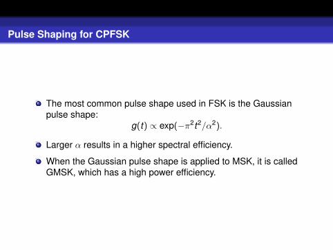
Pulse Shaping for CPFSK
The most common pulse shape used in FSK is the Gaussianpulse shape:
g(t) ∝ exp(−π2t2/α2).
Larger α results in a higher spectral efficiency.
When the Gaussian pulse shape is applied to MSK, it is calledGMSK, which has a high power efficiency.

Homework 4
Problem 1. Derive the Nyquist criterion of inter-symbolinterference in the frequency domain.
Problem 2. Verify (either analytically or numerical) that thecosine pulses satisfy the Nyquist criterion.
Problem 3. Show that the minimum frequency separation forFSK such that the cos(2πfj t) and cos(2πfi t) are orthogonal is∆f = mini 6=j |fi − fj | = 0.5/Ts.

Symbol Synchronization and Carrier Phase Recovery
One of the most challenging tasks of a digital demodulatoris to acquire accurate symbol timing and carrier phaseinformation.Timing information is needed to delineate the receivedsignal associated with a given symbol.The carrier phase information is needed in all coherentdemodulators for both amplitude/phase and frequencymodulation.

Receiver Structure
We denote by θ the unknown parameter vector (φ, τ),where φ is the unknown phase and τ is the unknowntiming.We can estimate them using likelihood function.

Phase Recovery
The optimal solution for the timing is given by the equation∑k sI(k) ∂∂r zk (τ)=0, which can be realized by the above
structure.
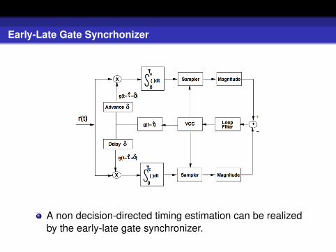
Early-Late Gate Syncrhonizer
A non decision-directed timing estimation can be realizedby the early-late gate synchronizer.