ECE137b Third Design Project Option - Electrical and ... ECE137b Third Design Project Option You...
13
1 ECE137b Third Design Project Option You must purchase lead-free solder from the electronics shop. Do not purchase solder elsewhere, as it will likely be tin/lead solder, which is toxic. "Solder-sucker" desoldering tools are not permitted in the lab, as they disperse a dust of solder granules into the air and onto surrounding surfaces. If you are also foolishly using tin/lead solder, you will then poison yourself. Again, use lead-free solder from the shop, and use desoldering wick to remove solder. Projects assembled using lead-containing solder will receive a grade of zero. GENERAL COMMENTS ........................................................................................................................... 2 CONSTRUCTION HINTS ............................................................................................................................... 2 BACKGROUND- ACOUSTIC (AND OTHER) PHASED ARRAYS ..................................................... 2 SPECIFIC CHALLENGE #1: FOCUSING SOUND: ............................................................................................. 7 POWER AMPLIFIERS .................................................................................................................................... 9 CHOICE OF IMPLEMENTATION ................................................................................................................... 10 microprocessor approach ................................................................................................................... 10 Delay element approach ..................................................................................................................... 10 THE SPECIFIC ASSIGNMENT .............................................................................................................. 11 FIRST CHECK OFF DATE: ........................................................................................................................... 11 SECOND CHECK OFF DATE......................................................................................................................... 12 THIRD CHECK OFF DATE............................................................................................................................ 12
Transcript of ECE137b Third Design Project Option - Electrical and ... ECE137b Third Design Project Option You...

1
ECE137b Third Design Project Option
You must purchase lead-free solder from the electronics shop. Do not purchase solder
elsewhere, as it will likely be tin/lead solder, which is toxic. "Solder-sucker"
desoldering tools are not permitted in the lab, as they disperse a dust of solder granules
into the air and onto surrounding surfaces. If you are also foolishly using tin/lead
solder, you will then poison yourself. Again, use lead-free solder from the shop, and use
desoldering wick to remove solder. Projects assembled using lead-containing solder will
receive a grade of zero.
GENERAL COMMENTS ........................................................................................................................... 2
CONSTRUCTION HINTS ............................................................................................................................... 2
BACKGROUND- ACOUSTIC (AND OTHER) PHASED ARRAYS ..................................................... 2
SPECIFIC CHALLENGE #1: FOCUSING SOUND: ............................................................................................. 7 POWER AMPLIFIERS .................................................................................................................................... 9 CHOICE OF IMPLEMENTATION ................................................................................................................... 10
microprocessor approach ................................................................................................................... 10 Delay element approach ..................................................................................................................... 10
THE SPECIFIC ASSIGNMENT .............................................................................................................. 11
FIRST CHECK OFF DATE: ........................................................................................................................... 11 SECOND CHECK OFF DATE ......................................................................................................................... 12 THIRD CHECK OFF DATE ............................................................................................................................ 12

2
General Comments
You have a choice of doing one of three design projects, a fiber optic link, a switched
mode power amplifier, or an acoustic phased array. All are intended to be
-Representative of real applications, incorporating aspects of both circuit and system
design.
- Highly independent in character. It is strongly expected that there should be minimal
similarity between projects designed by different groups.
-A significant fraction of the class grade and hence a significant time commitment
You will be working in groups of 2.
Construction Hints
These are high frequency circuits. Construction on a proto-board is of value for DC
testing and for AC functional testing at signal frequency well below that of the real
design. Functional high speed operation will require a soldered design with tight physical
construction practices. Construction on a circuit board with a ground plane is very
strongly recommended, as is signal wiring with adhesive copper tape. See the 137a web
site for information on construction practices.
Background- Acoustic (and other) Phased Arrays
Let us quickly review a set of ideas from wave diffraction and constructive and
destructive interference. Suppose we wished to direct sound from an array of speakers to
a single point, represented by a microphone, as in Figure 1 below.

3
Figure 1: Array of speakers delivering signals to a microphone.
We must now understand a small amount about sound. The speakers produce a sound
pressure p (lowercase p !) proportional to the voltage applied to them. Electrical signal
power is proportional to the square of voltage, 2
electricalP V , while acoustic signal power
is proportional to the square of the acoustic signal pressure 2
acousticP p .
Between speaker 1 and the microphone, at the intended focus point, we have a distance
1R . You can calculate this easily from geometry. The signal will get weaker from the
propagation distance, and will be delayed because of the path length 1R and the speed of
sound. At sea level, sound in air travels at approximate 343 m/s (look it up).
If speaker one is driven with a voltage ker,1 1( ) cos(2 )speaV t V ft , then the microphone
will produce a voltage ,1 1 1 1( ) cos(2 ( ))mic oV t R R KV f t T . Here K and 0R are
constants involving the properties of the speaker and the microphones. Note that acoustic
pressure, and the microphone signal voltage, are decreasing in amplitude in proportion to
11/ R , and that there is a time delay 1 1 / soundT R v , where soundv is the speed of sound.
The acoustic power at the microphone is proportional to the square of the pressure. The
electrical output power of the microphone is, of course, proportional to the square of the
microphone voltage.
If we have N speakers, and *all* are driven by the same voltage
ker, ( ) cos(2 )spea all allV t V ft , then the signal voltage at the microphone will be

4
, 1 2
1 2
( ) cos(2 ( )) cos(2 ( )) ... cos(2 ( ))o o omic total all N
N
R R RV t KV f t T f t T f t T
R R R
Because the time delays 1T , 2T , … are all different, the signals will add out of phase at
the microphone, and the microphone signal voltage will not be N times that produced by
a single speaker.
Figure 2: Acoustic phased array: added delays bring the speaker signals into phase at the
microphone.
If (Figure 2), we add signal path delays 1 2, , …, then the microphone signal becomes
, 1 1 2 2
1 2
( ) cos(2 ( )) cos(2 ( )) ... cos(2 ( ))o o omic total all N N
N
R R RV t KV f t T f t T f t T
R R R
If we set the electrical time delays such that the total delays 1 1( )T , 2 2( )T , … are
all equal, then the speaker signals will add in phase at the microphone. The signal voltage
produced by the microphone will then increase in proportion to the number of speakers
N , and the signal power will increase as 2N . This is called constructive interference.

5
Figure 3: Measuring the sound pressure at some position other than the intended focus.
What about the sound pressure at other positions ? If we now move the microphone, then
the path lengths all change, and the total delays 1 1( )T , 2 2( )T , … are no longer
equal. The signals do not add in phase, the signal voltage produced by the microphone do
not increase in proportion to the number of speakers N , and the signal power will not
increase as 2N . The signal is weaker: we do not have constructive interference.
Concisely, the microphone has been moved away from the focus. The array of speakers,
with the added time delays, is focusing sound. We can reverse the system, putting a
speaker at the focal position, and using an array of microphones. In this manner, we can
listen to sound at one specific location. The combination of the focusing acoustic
transmitter and receiver is an acoustic imaging system. We have just analyzed an
acoustic phased array. These are used in acoustic imaging (sonar) and in ultrasonic
imaging in medicine. Identical techniques are used in radar to identify the direction of
various objects being tracked. The physical principles, and the method of analysis, are
very close to those involved with the focusing properties of lenses, the angular radiation
patterns of antennas, and the angular diffraction pattern of gratings..
Over how large an area in the (x,y) plane would we expect the system to focus sound ? In
three dimensions, this would be a region in (x,y,z). The width of the focused spot in the
y-direction is called the focused beam diameter, while the length of the focused spot in
the x-direction is called the focal waist length.
We are focusing sound using a finite number of speakers. This introduces some
complications into the discussion. If we were using infinite array of infinitely small
6
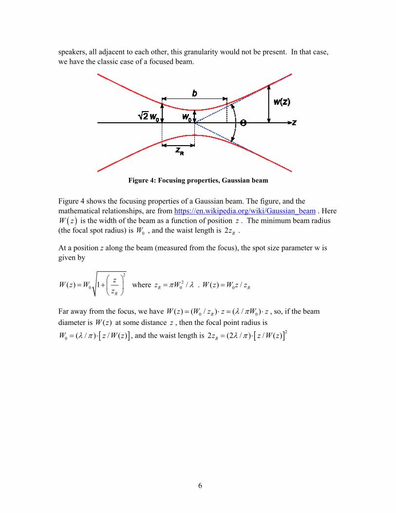
speakers, all adjacent to each other, this granularity would not be present. In that case,
we have the classic case of a focused beam.
Figure 4: Focusing properties, Gaussian beam
Figure 4 shows the focusing properties of a Gaussian beam. The figure, and the
mathematical relationships, are from https://en.wikipedia.org/wiki/Gaussian_beam . Here
W z is the width of the beam as a function of position z . The minimum beam radius
(the focal spot radius) is 0W , and the waist length is 2 Rz .
At a position z along the beam (measured from the focus), the spot size parameter w is
given by
2
0( ) 1R
zW z W
z
where 2
0 /Rz W . 0( ) / RW z W z z
Far away from the focus, we have 0 0( ) ( / ) ( / )RW z W z z W z , so, if the beam
diameter is ( )W z at some distance z , then the focal point radius is
0 ( / ) / ( )W z W z , and the waist length is 2
2 (2 / ) / ( )Rz z W z

7
Figure 5: Relating focal parameters to the speaker array
Unfortunately, Wikipedia is using a different set of (x,y,z) axes than we have been using.
We can nevertheless relate Wikipedia's analysis to our problem (Figure 5), in particular,
we have a focal point radius 0 ( / ) /focus focusW Z W and a waist length
2
2 (2 / ) /R focus focusz Z W
Assignment: You must write a MATLAB program which computes the acoustic
intensity as a function of position
Aliasing: The sound is focused at one point because, as we move away from the speakers,
the signals from the speakers become out of phase at the microphone. Because there are
a finite set of speakers at discrete locations, there will be other, unwanted locations at
which the signals from sets of speakers become 360 degrees out of phase, i.e. again
become in phase. These false, unwanted focal points arise from similar effects as higher-
order diffraction from diffraction gratings. There is also a strong relationship to
frequency aliasing in sampled-time systems. If you move the speakers very far apart,
expect to see strong false focusing points.
Specific Challenge #1: focusing sound:
I saw this device (overhead) in a museum, used to strongly localize the delivery of sound
to people standing close to a specific display. It had about 100 small speakers in
concentric rings.

8
Suppose we have an array of 19 speakers in the circular pattern at left, or (somewhat less
exactly, but easier to measure) an array of 19 speakers on the hexagonal pattern at right.
If we examine this problem edge-on, we can equalize the path lengths for an on-center
receiver with two time delay elements:
delay 1
delay 2

9
Power amplifiers
pushpullstage
R1
R2
Cc
Rx
L
Some kind of small audio power amplifier must be designed. Three are needed to drive
the 3 separate speaker rings. One amplifier must drive 12 parallel speakers, a 0.75 Ohm
load, hence design is not trivial. To simplify the task, use a Bi-FET op-amp
(LF351/LF353 series) with a bipolar or FET output stage. The xR /L output network
improves loop stability given a capacitive load. cC is a loop compensation capacitor.
Further details of the design will be given during the lab review.
The push pull stage can be very simple, like that below. Think about the output current
and the required transistor size
Given the very low load impedance associated with up to 12 speakers in parallel, it would
be wise to use series-parallel arrangements

10
Given the voltage division associated with this, you will need to appropriately adjust the
voltage gains of the op-amp stages. ,
Choice of implementation
You have two choices for the lab. You can use analog signal processing, using op-amp
delay states, or you can synthesize the signals using a small microprocessor with build-in
DACs.
microprocessor approach
please speak to the TA about this.
Delay element approach
If we use analog signal processing, Time delay elements 1 , 2 must be realized. In the
ideal case, a delay 1 would have transfer function )exp()( 11 jjH , hence
1||)(|| 1 jH and 11 ))((angle jH . Short of using a transmission-line of ~km
length, this can only be approximated.
A better solution is to use a set of N active filters in cascade: N
ii jhjH )}({)( . We
pick )( jhi to have close to unity magnitude and linear phase over the desired frequency
range, and then cascade a series of these to obtain the necessary total phase shift (total
delay).

11
The necessary delay can be approximated by using an active filter.
http://www.ti.com/lit/an/snoa224a/snoa224a.pdf and
OA-21 (see the class web page under resources) are good references. With these, you
synthesize a second-order transfer function with the desired damping factor and natural
resonant frequency
Possibly the best choice of active filter section is the one shown below. Please derive the
transfer function for this. It has constant gain amplitude at all frequencies and nearly
linear phase over quite a wide frequency range. A cascade of some number of these
filters should work well in producing the necessary time delays.
R
C
R
R
The Specific assignment
Your objective is to demonstrate the focusing of sound, building hardware to do this,
modeling it mathematically both by hand and by a computer program you write, and
comparing the measurements with the hand calculations and the computer simulations.
To realize this, you must
1) characterize the characeteristics of the speaker/microphone combination.
2) build 3 audio power amplifiers to drive these. One Amplifier must drive 1 speaker, one
must drive 6 speakers, one must drive 12 speakers.
3) Synthesize the time delays either using analog delay stages or a microprocessor with
DACs.
4) Connect the system and measure the acoustic intensity as a function of position.
5) write a Matlab program to compute what you should expect to measure, and compare
this analysis with your measurement.
The project has three check off dates
First Check off date:
a) Measure the speaker's frequency response. To do this, make the configuration below,
with the speakers separated by several feet, and measure Vout/Vin. Note that the

12
speakers are mounted on a baffle board, and that the speakers must be mounted in a hole
in the board rather than mounted stuck onto the board----this blocks the acoustic signal
from the back side of the speaker.
50 50
5 k
Vin Vout
board board
The speakers should be separated by at least 10 times the piston diameter. Vary the
frequency and determine the useful frequency range.. Higher frequencies will make the
wavelength shorter and allow you to focus sound using a smaller diameter for the speaker
array
Second check off date
a) Demonstrate the audio power amplifier. Demonstrate that it may stably drive a low
(3/4 Ohm load). You may use a Bi-FET op-amp (as shown above) as part of the
amplifier, but you must use a full-custom discrete component output stage for this.
The gain, frequency response, and maximum peak-peak signal swing should be
measured.
b) Write and demonstrate the MATLAB code to compute the frequency response vs.
position for the 19-element array. You are free to choose the array diameter and focal
length; pick reasonable dimensions , or phase III testing will be hard.
Third check off date
Demonstrate the full system.
a) Demonstrate the acoustic focusing. Measure the acoustic intensity vs position, moving
in the plane of the focal point, in a plane closer by one/half waist length to the speaker
array than the focal point, and in a plane further away by one/half waist length to the
speaker array than the focal point

13
b) compare your measurements with MATLAB simulation and to hand calculations using
the Gaussian beam formulas. Explain any discrepancies. Your experiment must make
sense.