ECE 662 – Microwave Electronics Klystrons March 31, April 7, 2005.
Upload
benedict-burkeCategory
view
216download
0
ECE 662 – Microwave Electronics
Cross-Field Devices:
Magnetrons
April 7, 14, 2005

Magnetrons• Early microwave device
– Concept invented by Hull in 1913– Initial devices in 1920’s and 30’s
• Cavity Magnetron (UK) – 10 kW– Rapid engineering and Production– Radiation Lab (MIT) established
• Relativistic Cavity Magnetron (1975) –900MW
• Advanced Relativistic Magnetrons (1986) - 8 GW
• Commercial Magnetrons (2003) - 5 MW

Magnetrons• Inherently efficient• Delivers large powers (up to GW pulsed
power and MW cw)• Limited electronic tuning, i.e., BW limited• Low cost• Industrial uses
– microwave ovens– industrial heating– drying wood– processing and bonding materials

Magnetrons
• B no longer used to confine electron beam as in a Klystron - B is an integral part of rf interation.
• Multicavity block• Coaxial cathode• Coupling - I/O- loop or Waveguide

ZZ

Planar MagnetronLet VA = potential differencebetween the anode andcathode, and E0=- VA /d. Anapplied magnetic field is in the x direction (into the paper). The force on the electrons becomes:
m
eB
dt
dy
dt
dyB
m
e
dt
zd
dt
dz
m
e
dt
dzB
m
e
dt
yd
vdt
dx
dt
xd
xByBvmF
cc
c
x
where;][
E]E[
)(initially zero be toassume0
ˆ ,ˆE ,]e[Edv/dt
02
2
0002
2
02
2
0000
x z

Planar Magnetron
z0z000y0
z000y0
y000z0y0z0
00
0022
2
2
0
v]cos1][v)/E[(sinv
sin]v)/E[(cosv
vN );/E(- vvq and vp 0, t
cossin
cossin
)/E(sincos
)/E(
E& &qLet
tBtdt
dz
tBtdt
dy
BMat
tNtMq
tNtMqdt
dp
BtNtMp
Bpdt
pd
pm
e
dt
dqq
dt
dp
dt
dzp
dt
dy
cc
cc
cc
ccccc
cc
cc
cc

Planar Magnetron
)t(B
Etsin)B/Ev()tcos1)(/v()t(z
)1t)(cosvB/E)(/1(tsin)/v()t(y
0
0
c
c000zcc0y
c0z00ccc0y

Planar Magnetron
2
0c
0
2
c
0
2
0c
0
2
0
0
00y0z
B
Ev
B
Ey)t(
B
Ez
as written becan result then this,vv and 0v If
This neglects space charge - tends tomake trajectory more “straight”.Result - frequency of cycloidal motionis c f B and (e/m)
KEY: average drift velocity of electrons in z direction is E0/B0 , independent of vz0 and vy0.

uox here is the v0z of our formulation
ref: Gerwartowski

Planar Magnetron
Electrons have dc motion equal to E0/B0, slow wave structure isassumed to be a propagating wave in the direction of theelectron flow with a phase velocity equal to E0/B0

Planar Magnetron (ref. Hemenway)

Planar Magnetron (ref. Hemenway)

Circular Magnetron (conventional geometry)
Electrons tend to move parallel tothe cathode. Aftera few periods inthe cylindricalgeometry theelectron cloud soformed is knownas the Brillouincloud. A ringforms around thecathode.

Circular Magnetron Oscillator ref: Gewartowski

Brillouin CloudNext, compute the electron angular velocity d/dt for actual geometry. Note region I inside the Brillouincloud and region II outside.
constantr2dt
drr
2dt
d
dt
drr
dt
dr
dt
d
(2)eqn y b (2); ,dt
drB
m
e
dt
dr
dt
d
r
1
0dt
zd (1); ,
dt
drBE
m
e
dt
dr
dt
rd
motion of sEquation
2c22cc
2
z2
2
2
zr
2
2
2

Brillouin Cloud
2
2cc
2c
cc
r
r1
2dt
d
r2
-constant 0dt
d ,rr At
Note: electrons at the outermost radius of the cloud (r = r0)move faster than those for r < r0. The kinetic energy (of theelectrons) increase is due to drop in potential energy.
m
eB where,
r
rr
8m
eBr/r1
4r
2e
mV
dt
dr
dt
dr that Assume
dt
dr
dt
dr
2e
mv
2e
mVor eVmv
2
1
c
22c
220
222c
2c2
2222

Hull Cutoff Condition
For a given B0, the maximum potential difference VA that can beapplied between the anode and cathode, for which the Brillouincloud will fill the space to r = ra is
condition cutoff Hull the,rr
rV
e
m8B
:gap cathode-anode thefilling avoid torequired B
minimum a Vgiven afor or r
rr
8m
eBV
2
2c
2a
aA
20
A
2
a
2c
2a
20
A
min
max

Hull Cutoff ConditionB0 < B0min direct current flows to anodeand no chance for interaction with rf.B0 > B0min Brillouin cloud has an outer radius r0 < ra and no direct currentflows to the anode. For a typicalmagnetron, B0 > B0min therefore r0 < ra
A
2
0
220
20
0
220
V 0.2) to(0.1 8m
eB)rV(r generally,
magnetron, a designing Gauss.in B and cmin r in volts, is
wherecondition cutoff Hull the, 5.45Bmin
r
rr
InV
rr
rV
c
A
ca
aA

Magnetron FieldsFrom radial force equation (1), consider electrons following circular trajectory in Brillouin cloud. Assume that
4
c2
0Ir
2
c
2
c2
20
Ir
2
2c
2
2c
22c
Ir
c0
2
Ir
0r2
2
r
r1r
4
)B(
m
eE
r
r1
2
1
r
r1
m
)eB(
e
m
2
rE
1r
r1
2
1
r
rr
2m/e
rE
dt
dfor result insert the ),(
m/e
rBr
m/e
rE
:)r(r I,region inEfor solve and small, sidt
rd

Magnetron FieldsFrom Poisson’s equation the charge density:
4
0
20
4
00
44
5
42
4
20
42
r
r0
00
12
)(12
2124)1(2
4
)(
m where,)1()E(
)E(
r
rB
m
e
r
r
r
r
r
rr
r
rr
r
rr
Be
r
rr
rr
r
rrr
E
cc
cccc
cI
I
0 falls slightly as r increases from rc (can increase 0 by increasingB0 which follows as electrons spiral in smaller cycloidal orbitsabout the cathode.
0

Magnetron Fields
]r
rr[
r
1
4m
)B(eEor ]
r2
rr[rdz2E
dz2m
)B(e2 where],
r2
r
2
r[
]r
r
2
1
r
r
2
1
2
r
2
r[dr)
r
rr(
dz dr r2)r(Qrdz2E dsD
20
4c
40
20
IIr20
4c2
0IIr0
02
012
0
4c
20
1
2c
4c
20
4c
2c
20
13
4c
r
r
1
r
r
0
surface
enclIIr0
0
c
0
c
Outside the Brillouin cloud, r0 < r < ra, in region II, use Gauss’sTheorem:

Hartree Relationship
ipRelationsh Hartree ,)
r
rln()
r
rr(2
r
rr
8m
)B(e
rln)r
rr(
r
r
2
1
2
r
4m
)B(e
dr]r
rr[
r
1
4m
)B(edr)
r
r1(r
4m
)B(e
drEdrEdrEV
0
a2
0
4c
40
20
22c
20
20
r
r
20
4c
40
r
r
2
4c
220
r
r2
0
4c
40
20
r
r4
4c
20
r
r
rII
r
r
rI
r
r
rA
a
0
0
c
a
0
0
c
a
0
0
c
a
c
The potential difference VA between the cathode and anode tomaintain the Brillouin cloud of outer radius r0 is given by:

Hartree Relationship
00
2c
20c
0B
B
20
4c
400c
BA
0
a
0
a2
0
4c
40
20
22c
20
20
A
rrat velocity circular)r
rr(
2rv
rrat voltageis V is where,
)r
rr(
4
B
VV)
r
rln(
by expressed maybe ipRelationsh Hartree theor
)r
rln()
r
rr(2
r
rr
8m
)B(eV
0
This vB is important since it gives the velocity of the electrons at theouter radius of the Brillouin cloud. It is this velocity vB that is to match the velocity of the traveling waves on the multicavity structure.

Anode - Cathode Spacing
Desire microwave field repetition with spatial periodicity of the structure. This field will have traveling wave components the most important of which is a component traveling in the same direction withabout the same velocity, vB , as the outer ones in the Brillouin layer.
A0B
cac0
V 0.2) to1.0()rr(V
such that rr offraction small is rr
magnetron; theofsion planar ver heconsider t Again,

Anode - Cathode Spacing
These traveling waves are slow waves with the desired phase velocity, vp ~ vB. Consider the wave equation as follows:
celocityelectron v ,v~ vsince
vc
k
since ,0Ey
E E)k(
y
E
0x/ ,/v ,edirection zin travelingFields
0Ekz
E
y
E
x
EEkE
Bp
2p
22
2
22
22
222
2
2
pz)-tj(
22
2
2
2
2
222
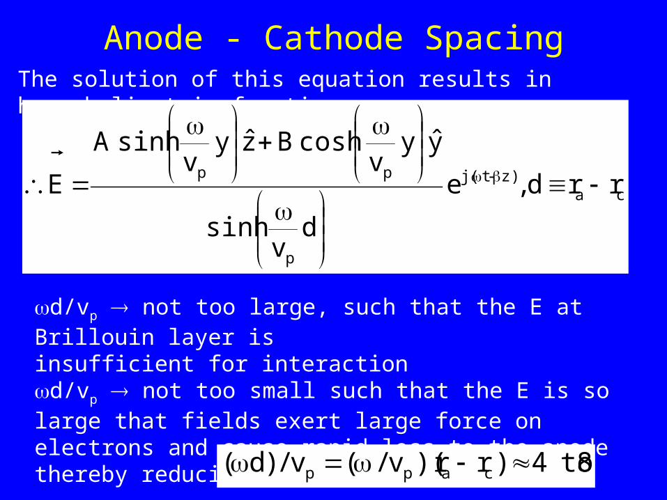
Anode - Cathode SpacingThe solution of this equation results in hyperbolic trig functions:
caz)-tj(
p
pprrd ,e
dv
sinh
yyv
cosh Bzyv
sinh A
E
d/vp not too large, such that the E at Brillouin layer is insufficient for interactiond/vp not too small such that the E is so large that fields exert large force on electrons and cause rapid loss to the anode thereby reducing efficiency. Typically,
8 to4)rr)(v/(v/)d( capp

Multicavity Circuit - Slow Wave Structure
Equivalent circuit of multicavity structure - here each cavity has been replaced by its LC equivalent. Thiscircuit is like a transmission linefilter “T” equivalent.
line coaxial from)r/rln(
2cathode and ecavity van
between ecapacitanc couplingC Cj
1Z
cavity uncoupled thengrepresentinetwork LC parallel
of impedance ZLC
1 ,
)/(1
LjZ
ca
0
cc
2
1020
1

Multicavity Circuit - Slow Wave Structure
The circuit acts like low-loss filter interactive impedance = input impedance of an infinite series ofidentical networks.
]})/(1[4/{LCsin 2)Z4/(Zsin 2 p
isfilter of psection per shift Phase band. pass theis 0)Z4/(Z1-
,)Z4/(Z1ZZZ ,4/ZZor 4/XXor real be to
4/XXX]XX)4/X[( ZthenjXZ ;jXZ If
delivered. ispower no Otherwise power. delivers and load resistance
sees""generator theresistive, pure isZZ If ]ZZ)4/Z[(Z
find tofor Z solve ,ZZ)2/Z(Z
Z]Z)2/Z[(
2
ZZ
20c
21-21
1-
21
2121k12ab
2aba
1/2ba
2akb2a1
kin1/2
212
1k
kkk12
2k11in

Multicavity Circuit - Slow Wave StructureRf field repeats with periodicity p (spacing of adjacent cavities). Field at distance z+np is same as z. = phase shift per unit length of phase constant of wave propagating down the structure.
mode. for thefrequency operating
theis )4/(1
.for solve ])/(1[4
12
sin
]})/(1[4/{sin 2p
cavity)(per mode or p N/2,mfor
0,1,2,3m ,36
m2p 6,Nfor N/2 ... 2, 1, 0,m 2
02
0
2
20
21-
CC
LC
orLC
mmNp
c
c
c
For a circular reentrant structure anode with N cavities, fields areindistinguishable for Z as for Z + np.

Fields and Charge Distributions for two Principal Modes of an Eight-Oscillator
Magnetron

Fields and Charge Distributions for two Principal Modes of an Eight-Oscillator
Magnetron


Multicavity Circuit - Slow Wave Structure
NrrNCCCC
C
C
N
cs
c
00p0
21-(N/2)
2 ,2/
v)4/(/1
:mode theoffrequency thelowers ecapacitanc
adds Strapping sun. rising and strapping- methods 2
separation thisincrease todesire - modes Competing
0.99 to97.01
41
mode 1-N/2m For the

Strapped Cavities

Typical Magnetron Cross-Sections (after Collins)
(a) Hole and slot resonators(b) Rectangular resonators(c) Sectoral resonators

Typical Magnetron Cross-Sections (after Collins)
(d) Single ring strap connecting alternate vanes(e) Rising sun anode with alternate resonators
of different shapes(f) Inverted magnetron with the cathode exterior
to the anode


The unfavorable electrons hit the cathode and give up as heat excess energy picked up from the field. As a result, the cathode heater can be lowered or even turned off as appropriate.
twotwo

Rotating wheel formed by the favorable electrons in a magnetron oscillating in the mode ref: Ghandi


General Design Procedures for Multicavity Magnetrons
V,I requirements: From Power required may select VA. High VA keeps current down and strain on cathode, but pulsed high voltage supplies are needed.Note Pin = P0 / efficiency and I A = Pin / VA= P0 / VA.
Cathode radius from available current densities for type of cathodestypically used in magnetrons.
Typically J0 (A/cm2) 0.1 to 1.0 for continuous, 1 to 10 for pulsed
Smaller J0 lower cathode temperature so longer life of tube
Too low J0 requires a larger rc

General Design Procedures for Multicavity Magnetrons
Emitting length of cathode (lc) < anode length, la ; Typically, lc ~ 0.7 to 0.9 la , and la < /2 (prevents higher order modes) Smaller la is consistent with power needs less B0 needed (less weight)
Radius r0 (top of Brillouin cloud) from velocity synchronism condition:
vp (r = r0) = r0 / (N/2) = [c r0 /2] [1- (rc2 / r0
2)]; thereforer0 = rc / [1-( /c)(4/N)]1/2
For an assumed B0, r0 can be calculated for a number of values of N (typically 6 to 16) or 20 to 30 for a small magnetron.

General Design Procedures for Multicavity Magnetrons
Voltage eVB (r = r0) = (1/2) mvB2 where vB = vp (r = r0) or
VB = (vB /5.93x107) 2 ; vB in cm/sec ; Hence VB ~ 0.1 to 0.2 VA
Note efficiency, < (1 - VB / VA )*100; henceSmaller VB / VA contributes to improved efficiency
Anode radius: ln (ra/ r0) = [VA - VB ] / {[c 2 / 4(e/m)][(r0
4 -rc 4 ) / r0
2 ]}
Also Bmin = (45.5 VA) 1/2 [ra /(ra 2 -rc
2 )] << B0
( /vp)( ra - rc) ~ 4 to 8 N must be even such that N phase shift around the circumference is a whole 2 .


Cutaway view of aCoaxial Magnetron


NRL Hybrid Inverted Coaxial
Magnetron

NRL Hybrid Inverted Coaxial Magnetron