ECE 477 Final Presentation Group 1 Spring 2005 · ECE 477 Final Presentation Group 1 −Spring 2005...
38
ECE 477 Final Presentation ECE 477 Final Presentation Group 1 Group 1 − − Spring 2005 Spring 2005 Zeeshan Nathan Nakul Andrew FIRE Bot
Transcript of ECE 477 Final Presentation Group 1 Spring 2005 · ECE 477 Final Presentation Group 1 −Spring 2005...

ECE 477 Final Presentation ECE 477 Final Presentation Group 1 Group 1 −− Spring 2005Spring 2005
Zeeshan NathanNakul Andrew
FIRE Bot

OutlineOutline
•• Project overviewProject overview•• Block diagramBlock diagram•• Professional componentsProfessional components•• Design componentsDesign components•• Success criteria demonstrationsSuccess criteria demonstrations•• Individual contributionsIndividual contributions•• Project summaryProject summary•• Questions / discussionQuestions / discussion

Project OverviewProject Overview•• FIREbot is a fully autonomous robot intended to FIREbot is a fully autonomous robot intended to
protect a home or small building from fires.protect a home or small building from fires.•• Patrols an indoor area or waits passively while Patrols an indoor area or waits passively while
searching for flamessearching for flames•• Capable of locating, approaching, and extinguishing Capable of locating, approaching, and extinguishing
flamesflames•• Uses a standard household fire extinguisher and an Uses a standard household fire extinguisher and an
easily rechargeable batteryeasily rechargeable battery•• Features an easy and convenient user interface to let Features an easy and convenient user interface to let
you select its mode of operation and see what its you select its mode of operation and see what its currently doingcurrently doing
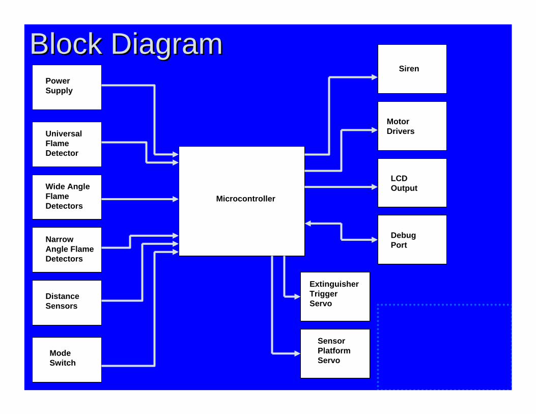
Block DiagramBlock DiagramPower Supply
Universal Flame Detector
Wide Angle Flame Detectors
Narrow Angle Flame Detectors
Distance Sensors
ModeSwitch
Siren
Sensor Platform Servo
Microcontroller
Motor Drivers
LCD Output
Debug Port
Extinguisher Trigger Servo

Professional ComponentsProfessional Components
•• Constraint analysis and component selection Constraint analysis and component selection rationalerationale
•• Patent liability analysisPatent liability analysis•• Reliability and safety analysisReliability and safety analysis•• Ethical and environmental impact analysisEthical and environmental impact analysis

Constraint AnalysisConstraint Analysis
•• Mechanical/Structural ConstraintsMechanical/Structural Constraints–– Capable of carrying and triggering fire Capable of carrying and triggering fire
extinguisherextinguisher–– Capable of positioning all sensors to Capable of positioning all sensors to
receive necessary datareceive necessary data–– Capable of being driven by small DC Capable of being driven by small DC
motorsmotors–– Capable of carrying and Capable of carrying and
protecting electronicsprotecting electronics

Constraint AnalysisConstraint Analysis
•• Electrical ConstraintsElectrical Constraints–– Powered by OnPowered by On--board batteryboard battery–– 4 Supply Rails4 Supply Rails–– Must be robust and powerMust be robust and power--efficientefficient–– Microcontroller receives all inputs and Microcontroller receives all inputs and
drives all outputsdrives all outputs–– Electronics to interface to each input Electronics to interface to each input
sensor and each output devicesensor and each output device

Constraint AnalysisConstraint Analysis
•• Software ConstraintsSoftware Constraints–– Software is interruptSoftware is interrupt--driven to allow realdriven to allow real--
time responsestime responses–– Control state machines to handle highControl state machines to handle high--
level intelligencelevel intelligence–– LowLow--level state machines to control all level state machines to control all
hardware moduleshardware modules

Patent Liability AnalysisPatent Liability Analysis
•• Patents exist forPatents exist for–– IR Fire detection systemIR Fire detection system–– IR Obstacle avoidance systemIR Obstacle avoidance system–– ““Automated Fire Protection SystemAutomated Fire Protection System””
““Designed for the protection of naval Designed for the protection of naval vessels from the danger exhibited by vessels from the danger exhibited by ordnances exposed to heat in the event of ordnances exposed to heat in the event of a fire.a fire.””

Reliability/Safety AnalysisReliability/Safety Analysis
•• Microcontroller analysisMicrocontroller analysis–– MTTF = 1.23MTTF = 1.23
•• MBR160 Switching supply MBR160 Switching supply schotkeyschotkey diodesdiodes–– MTTF = 2.2MTTF = 2.2
•• 5v linear regulator5v linear regulator–– MTTF = 1.88MTTF = 1.88–– Reduced by adding large heat sink to Reduced by adding large heat sink to
dissipate extra heatdissipate extra heat
Ethical/Environmental AnalysisEthical/Environmental Analysis• In the current version of production, there are no warning
labels anywhere on the robot.• No safeties mechanisms present on the robot other than
fuses.• If the fire is particularly large, the robot may not be
capable of putting it out.• All rechargeable batteries pose a potential environmental
hazard due to the presence of lead-acid.• All printed PCBs have lead as well.
Design ComponentsDesign Components
•• Packaging design considerationsPackaging design considerations•• Schematic design considerationsSchematic design considerations•• PCB layout design considerationsPCB layout design considerations•• Software design considerationsSoftware design considerations

Packaging DesignPackaging DesignLevel 2 bolt holes Extinguisher strap mounting holes
Motor mounting holes
User interface mounting holes
Servo mounting holes
Siren mounting holesBase – top view

Packaging DesignPackaging DesignLevel 2 mounting holes
Tower mounting holes
UVtron mounting holesLevel 2 – top view
Tower – sweeping turntable
Tower – narrow angle sensor

Packaging DesignPackaging Design
Angular bracket
RS232 debug interface
Mode selection switch
Power switch
4x20 LCD display

Schematic DesignSchematic Design•• Power supplyPower supply
–– Noise isolation accomplished with four power rails and two Noise isolation accomplished with four power rails and two ground railsground rails
•• Sensor interface circuitsSensor interface circuits–– Signal amplification required for low currentSignal amplification required for low current--output output
photodiodesphotodiodes–– Low noise requirements for most A/D inputsLow noise requirements for most A/D inputs
•• Shift registersShift registers–– Reduce microcontroller I/O pinsReduce microcontroller I/O pins–– Used for LCD and DC motor control outputsUsed for LCD and DC motor control outputs
•• Motor interface circuitsMotor interface circuits–– HH--bridges for PWM motor controlbridges for PWM motor control–– Dedicated power rail for servosDedicated power rail for servos

PCB Layout DesignPCB Layout Design

PCB Layout DesignPCB Layout Design
ATMega32
Digital Switching Power Supply
Servo Switching Power Supply
Serial Debug Port Siren
Analog Flame & Proximity Sensors`
Servo Motor Drivers
12V Switch
5V Linear Regulator
DC Motor H-Bridges
LCDDisplay Turntable
MountedPCB

Software DesignSoftware Design•• Code size: 14KBCode size: 14KB•• Software is heavily modularizedSoftware is heavily modularized•• All modules are interrupt driven state All modules are interrupt driven state
machinesmachines•• Software hierarchically organized into master Software hierarchically organized into master
control, mode control, and hardware control, mode control, and hardware interface control modulesinterface control modules
•• Organized development Organized development environment with a revisionenvironment with a revisioncontrol systemcontrol system

Software DesignSoftware DesignMaster Software
Mode Control Software
Hardware-Interface Software
Hardware

Software DesignSoftware Design
•• Master software Master software -- top level state machinetop level state machine•• Mode control softwareMode control software
–– One Eye Open ModeOne Eye Open Mode–– Patrol ModePatrol Mode–– FindFind--thethe--Fire Fire –– ApproachApproach–– ExtinguishExtinguish–– Debug interfaceDebug interface

Software DesignSoftware Design•• HardwareHardware--Interface softwareInterface software
–– Universal flame detectorUniversal flame detector–– Drive motorsDrive motors–– Obstacle/Proximity sensorsObstacle/Proximity sensors–– Narrow angle flame detectorNarrow angle flame detector–– Scanner & trigger servosScanner & trigger servos–– Wide angle flame detectorWide angle flame detector–– ADC controllerADC controller–– LCD interfaceLCD interface–– UART (debug) interfaceUART (debug) interface

Success Criteria DemonstrationsSuccess Criteria Demonstrations
•• Ability for the software to maneuver the Ability for the software to maneuver the robot on an arbitrary indoor surface, robot on an arbitrary indoor surface, avoiding walls or other objects while avoiding walls or other objects while maneuvering.maneuvering.

Success Criteria DemonstrationsSuccess Criteria Demonstrations

Success Criteria DemonstrationsSuccess Criteria Demonstrations
•• Ability to interface the microcontroller with Ability to interface the microcontroller with an LCD and display state information on the an LCD and display state information on the screen.screen.

Success Criteria DemonstrationsSuccess Criteria Demonstrations

Success Criteria DemonstrationsSuccess Criteria Demonstrations
•• Ability to detect a nearby fire with minimal Ability to detect a nearby fire with minimal false positives (from nonfalse positives (from non--flame heat flame heat sources) and determine the firesources) and determine the fire’’s position s position relative to the robot.relative to the robot.
•• Ability to maneuver the robot into position Ability to maneuver the robot into position to extinguish a fire based on data from the to extinguish a fire based on data from the sensors.sensors.
Success Criteria DemonstrationsSuccess Criteria Demonstrations

Success Criteria DemonstrationsSuccess Criteria Demonstrations
•• Ability to activate a fire extinguisher to Ability to activate a fire extinguisher to extinguish a fire when the robot is already extinguish a fire when the robot is already in the correct position.in the correct position.

Success Criteria DemonstrationsSuccess Criteria Demonstrations
Individual ContributionsIndividual Contributions
•• Team Leader Team Leader –– Nathan AinsworthNathan Ainsworth•• Team Member 2 Team Member 2 –– Nakul JeirathNakul Jeirath•• Team Member 3 Team Member 3 –– M. Zeeshan KhanM. Zeeshan Khan•• Team Member 4 Team Member 4 –– Andrew PennerAndrew Penner

Team Leader Team Leader –– Nathan AinsworthNathan Ainsworth
•• Coordinated Efforts of all team members Coordinated Efforts of all team members ((““SupervisedSupervised””))
•• Performed overall Systems Engineering of Performed overall Systems Engineering of FireFire--Finding ProcessesFinding Processes
•• Developed many blocks of the schematicsDeveloped many blocks of the schematics•• Developed overall software structureDeveloped overall software structure•• Developed many software blocksDeveloped many software blocks

Member 2 Member 2 –– Nakul JeirathNakul Jeirath
•• Designed LCD circuitryDesigned LCD circuitry•• Wrote software for modules:Wrote software for modules:
–– Wide angle flame detectorWide angle flame detector–– Patrol modePatrol mode–– Find the fire stateFind the fire state
•• PCB layoutPCB layout•• PCB PopulationPCB Population•• Mechanical structure designMechanical structure design
Member 3 Member 3 –– Zeeshan KhanZeeshan Khan
•• Wrote software for modules:Wrote software for modules:–– UART interfaceUART interface–– Obstacle detectionObstacle detection–– ADCADC
•• Software debuggingSoftware debugging•• Populated PCBPopulated PCB•• Team webmasterTeam webmaster•• Managed CVS archivesManaged CVS archives

Member 4 Member 4 –– Andrew PennerAndrew Penner
•• Designed power suppliesDesigned power supplies•• PCB LayoutPCB Layout•• PCB PopulationPCB Population•• Mechanical structure designMechanical structure design•• Hardware testingHardware testing•• Software debuggingSoftware debugging
Project SummaryProject SummaryWe learned the importance ofWe learned the importance of……•• modularized softwaremodularized software•• capable debug interfacecapable debug interface•• planning topplanning top--down & implementing bottomdown & implementing bottom--upup•• maintaining a well organized development maintaining a well organized development
environmentenvironment–– revision control systemrevision control system–– standards in software & standards in software &
schematic designschematic design•• strong teamwork skillsstrong teamwork skills

Project SummaryProject SummarySuggestions for version 2Suggestions for version 2•• Choose a different narrowChoose a different narrow--angle sensorangle sensor•• Use more than one universal flame detectorUse more than one universal flame detector•• Add selfAdd self--charging capabilitycharging capability•• Choose distance sensors with digital output to Choose distance sensors with digital output to
reduce noisereduce noise•• Use a more sophisticated approach algorithmUse a more sophisticated approach algorithm•• Upgrade microcontroller for increased flexibilityUpgrade microcontroller for increased flexibility•• Correctly implement power shutdown featuresCorrectly implement power shutdown features•• Upgrade packaging to better protect electronicsUpgrade packaging to better protect electronics•• Use a COUse a CO22 fire extinguisherfire extinguisher•• Integrate fly wires into PCB layoutIntegrate fly wires into PCB layout

Questions / DiscussionQuestions / Discussion