ECE 265 – LECTURE 16 Complete System Example A Weight Measurement System 8/13/2015 1 ECE265.
17
ECE 265 – LECTURE 16 Complete System Example A Weight Measurement System 03/16/22 1 ECE265
-
Upload
spencer-boone -
Category
Documents
-
view
217 -
download
0
Transcript of ECE 265 – LECTURE 16 Complete System Example A Weight Measurement System 8/13/2015 1 ECE265.
ECE 265 – LECTURE 16
Complete System Example
A Weight Measurement System
04/19/23
1ECE265
Joanne E. DeGroat, OSU
Lecture Overview
System application example A point of sale weight measurement system Involves
Load cells and signal conditioning Application program
REF: Chapter 14 Many chapters plus the 68HC11 reference
manual.
04/19/23
2
ECE265

Joanne E. DeGroat, OSU
Statement of the Problem
A chain of hardware stores wants to automate checkout of small items to make the checkout process more efficient.
For nail, screws, washers, and other similar small items.
Each carries a different price and each items has an item weight.
When a bulk purchase of one of these items is made, the order is placed on the scale of the system and the clerk enters the product id.
The microcontroller weighs the order, the number of items and total price calculated.
04/19/23ECE265
3
Joanne E. DeGroat, OSU
Some background
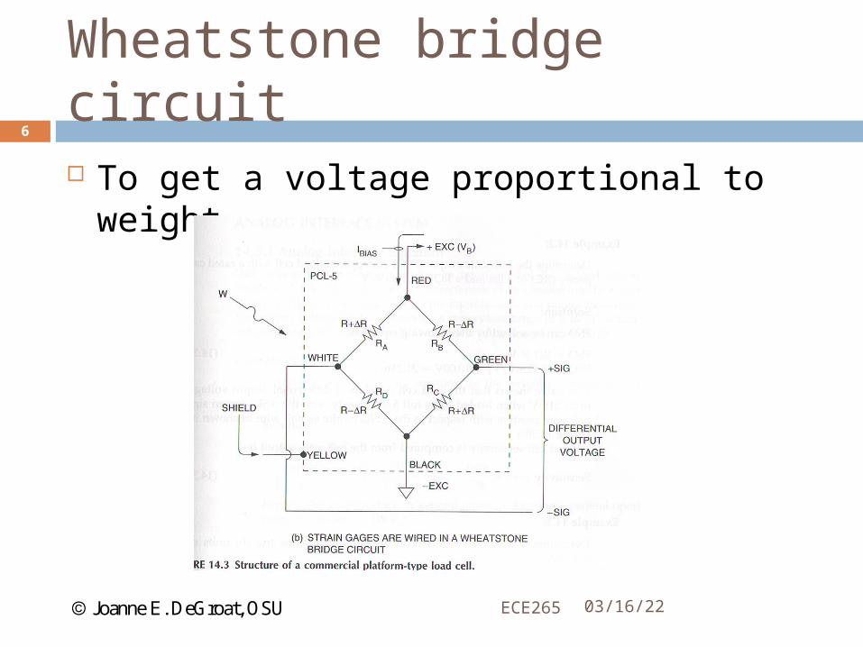
Load cells are transducers that covert applied force, such as weight, into a differential electrical output voltage signal.
Load cells – foil type strain gauges Use a Wheatstone bridge circuit to output a signal that
can be input to the microcontroller A/D. Foil type strain gauges measure the deflection of the
sensing beam to which they are attached. The beam deflects when a load is applied and thus the ability to measure weight is achieved.
04/19/23ECE265
4
Joanne E. DeGroat, OSU
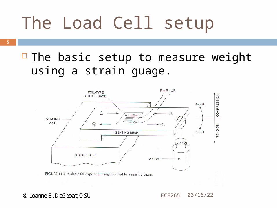
The Load Cell setup
The basic setup to measure weight using a strain guage.
04/19/23ECE265
5
Joanne E. DeGroat, OSU
Wheatstone bridge circuit
To get a voltage proportional to weight
04/19/23ECE265
6

Joanne E. DeGroat, OSU
Load Cell Specification
Parameters to specify Excitation voltage – typically a maximum Terminal resistance input – used to determine power
consumption – manufacturers specify minimum resistance.
Rated capacity – in pounds of kilograms Rated output – in mV/V – specifies the output signal
per pound given an input voltage of V
04/19/23ECE265
7
Joanne E. DeGroat, OSU
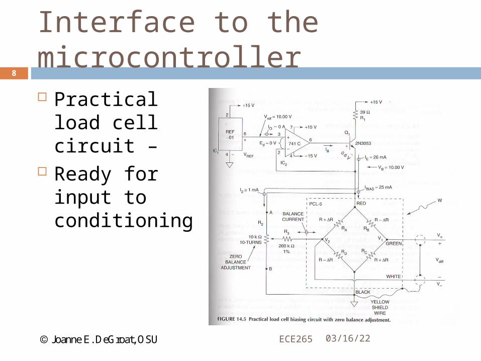
Interface to the microcontroller
Practical load cell circuit –
Ready for input to conditioning
04/19/23ECE265
8
Joanne E. DeGroat, OSU
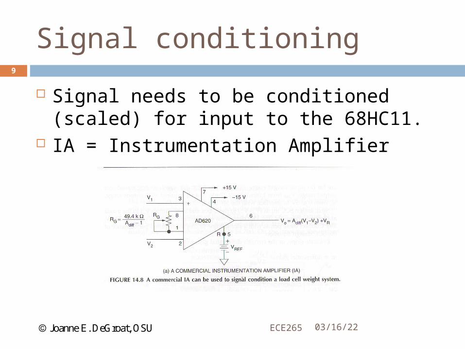
Signal conditioning
Signal needs to be conditioned (scaled) for input to the 68HC11.
IA = Instrumentation Amplifier
04/19/23ECE265
9
Joanne E. DeGroat, OSU
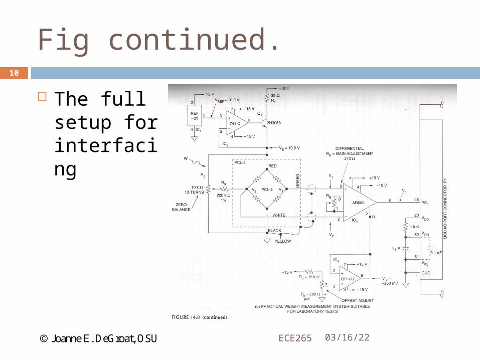
Fig continued.
The full setup for interfacing
04/19/23ECE265
10
Joanne E. DeGroat, OSU
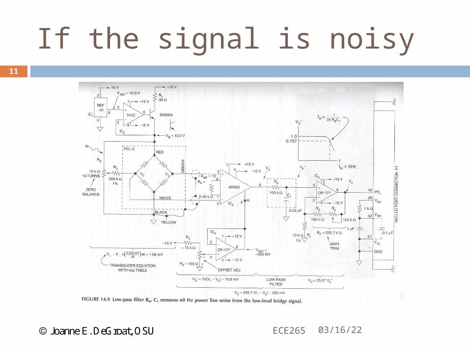
If the signal is noisy
04/19/23ECE265
11

Joanne E. DeGroat, OSU
Software design
An overall flowchart /pseudocode
Start at this high level and then break down each function
04/19/23ECE265
12
Joanne E. DeGroat, OSU
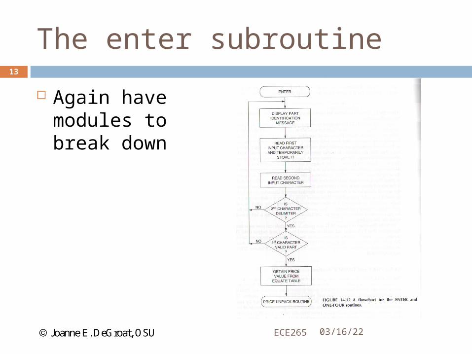
The enter subroutine
Again have modules to break down
04/19/23ECE265
13
Joanne E. DeGroat, OSU
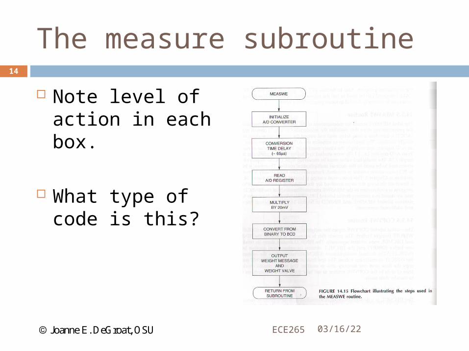
The measure subroutine
Note level of action in each box.
What type of code is this?
04/19/23ECE265
14
Joanne E. DeGroat, OSU
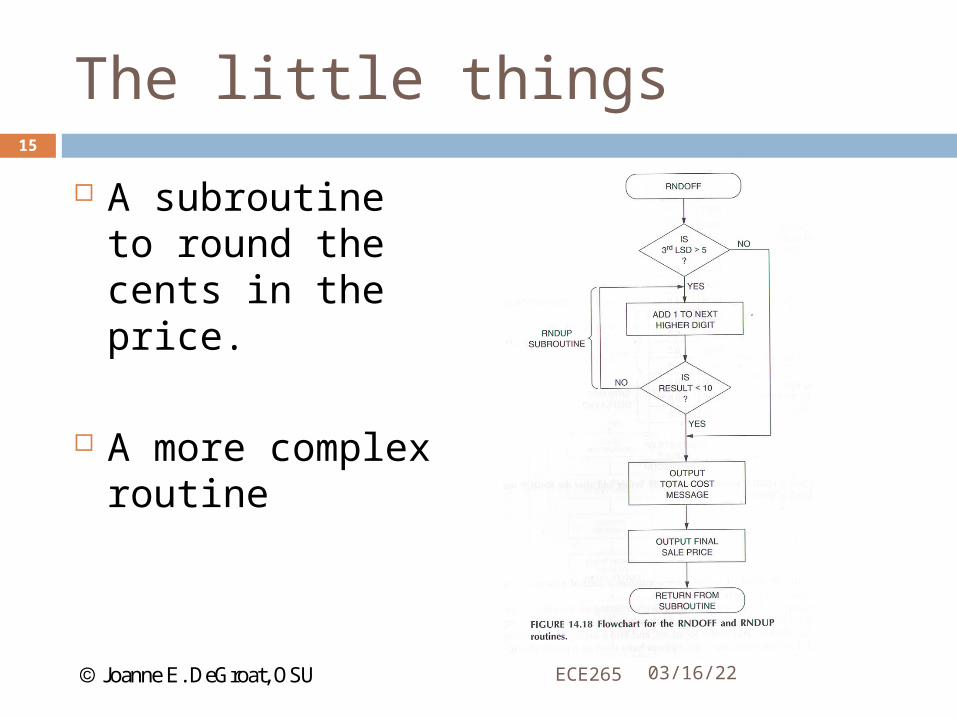
The little things
A subroutine to round the cents in the price.
A more complex routine
04/19/23ECE265
15
Joanne E. DeGroat, OSU
Lecture summary
04/19/23ECE265
16
In this lecture we have looked at a system implementation where a microcontroller would be used.
System in an integration of both hardware and software design and implementation.
The software for the system is 8 ½ pages in chapter.
Note the documentation within the software code!!!
Joanne E. DeGroat, OSU
Assignment
04/19/23ECE265
17
None