ECA 71 protocol for the ECL Comfort 200/300 series...
26
ECA 71 protocol for the ECL Comfort 200/300 series Instructions DH-SMT/DK VI.KP.O2.02 © Danfoss 02/2008 DH-SMT/DK VI.KP.O2.02 © Danfoss 02/2008
Transcript of ECA 71 protocol for the ECL Comfort 200/300 series...

ECA 71 protocolfor the ECL Comfort 200/300 series
Instructions
DH-SMT/DK VI.KP.O2.02 © Danfoss 02/2008
DH-SMT/DK VI.KP.O2.02 © Danfoss 02/2008

VI.KP.O2.02 © Danfoss 02/2008 DH-SMT/DK
Instructions ECA 71 protocol for the ECL Comfort 200/300 series
Table of Contents
1. Introduction 11.1 How to use these instructions ................................................................................................................................................................................................11.2 About the ECA 71 ........................................................................................................................................................................................................................11.3 Compatibility .................................................................................................................................................................................................................................2
2. Configuration 32.1 Network description ...................................................................................................................................................................................................................32.2 Mounting and wiring of the ECA 71 .....................................................................................................................................................................................42.3 Add devices to the network .....................................................................................................................................................................................................62.3.1 Setup of addresses in the ECL Comfort 200/300/301 ....................................................................................................................................................6
3. General parameter description 83.1 Parameter naming .......................................................................................................................................................................................................................83.2 Control parameters .....................................................................................................................................................................................................................83.3 Schedules ........................................................................................................................................................................................................................................83.4 Mode and status...........................................................................................................................................................................................................................83.5 Time and date ...............................................................................................................................................................................................................................93.6 Heat meter data............................................................................................................................................................................................................................93.7 Special parameters ......................................................................................................................................................................................................................9
4 Good behaviour in designing a district heating MODBUS network 104.1 Considerations before implementing communication ..............................................................................................................................................104.2 Basic needs for information in SCADA systems .............................................................................................................................................................104.3 Final number of nodes in the network ..............................................................................................................................................................................114.4 Parallel network .........................................................................................................................................................................................................................114.5 Bandwidth considerations .....................................................................................................................................................................................................114.6 Update rate from the ECL Comfort controller.................................................................................................................................................................114.7 Minimize the copy of data in the network .......................................................................................................................................................................124.8 Network layouts .........................................................................................................................................................................................................................12
5. Protocol 135.1 Function codes ...........................................................................................................................................................................................................................135.1.1 Function codes overview ........................................................................................................................................................................................................135.1.2 MODBUS/ECA 71 messages ...................................................................................................................................................................................................135.1.2.1 Read read-only parameter (0x03) ........................................................................................................................................................................................135.1.2.2 Read parameters (0x04) ..........................................................................................................................................................................................................145.1.2.3 Write parameter number (0x06) ..........................................................................................................................................................................................145.2 Broadcasts ....................................................................................................................................................................................................................................155.3 Error codes....................................................................................................................................................................................................................................15
6. Dismounting 15
Appendix 16Parameter list .............................................................................................................................................................................................................................................16

DH-SMT/DK VI.KP.O2.02 © Danfoss 02/2008 1
Instructions ECA 71 protocol for the ECL Comfort 200/300 series
1. Introduction1.1 How to use these instructions
Software and documentation for ECA 71 can be downloaded from http://heating.danfoss.com.
Safety NoteTo avoid injury of persons and damages to the device, it is absolutely necessary to read and observe these instructions carefully. The warning sign is used to emphasize special conditions that should be taken into consideration.
This symbol indicates that this particular piece of information should be read with special attention.
1.2 About the ECA 71
The ECA 71 MODBUS communication module makes it possible to establish a MODBUS network with standard network components. Via a SCADA system (OPC Client) and the Danfoss OPC server it is possible to control the controllers in the ECL Comfort in the 200/300 series remotely.
ECA 71 can be used for all application cards in the ECL Comfort 200 series as well as in the 300 series. The ECA 71 with proprietary protocol for ECL Comfort is based on MODBUS®.
Accessible parameters (card dependent):• Sensor values• References and desired values• Manual override• Output status• Mode indicators and status• Heat curve and parallel displacement• Flow and return temperature limitations• Schedules• Heat meter data (only in ECL Comfort 300 as of version 1.10 and only if ECA 73 is mounted)

2 VI.KP.O2.02 © Danfoss 02/2008 DH-SMT/DK
Instructions ECA 71 protocol for the ECL Comfort 200/300 series
1.3 Compatibility
Optional ECA modules:The ECA 71 is compatible with ECA 60-63, ECA 73, ECA 80, ECA 83, ECA 86 and ECA 88. Max. 2 ECA modules can be connected.
ECL Comfort:ECL Comfort 200 series• As of ECL Comfort 200 version 1.09 ECA 71 is compatible, but an additional address tool is required. The address tool can be
downloaded from http://heating.danfoss.com.
ECL Comfort 300 series• The ECA 71 is fully compatible with ECL Comfort 300 as of version 1.10 (also known as ECL Comfort 300S) and there is no need
for an additional address tool. • ECL Comfort 300 as of version 1.08 is compatible, but an additional address tool is required.• All versions of ECL Comfort 301 and 302 are compatible, but an additional address tool is required.
Only ECL Comfort 300 as of version 1.10 can setup the address used in the ECA 71 module. All other ECL Comfort controllers will require an address tool to set up the address.
Only ECL Comfort 300 as of version 1.10 can handle the heat meter data from the ECA 73 module.

DH-SMT/DK VI.KP.O2.02 © Danfoss 02/2008 3
Instructions ECA 71 protocol for the ECL Comfort 200/300 series
2. Configuration2.1 Network description
The network used for this module is conditionally compliant (implementation class = basic) with the MODBUS over serial line two-wire RS-485 interface. The module uses the RTU transmission mode. Devices are connected directly to the network, i.e. daisy chained. The network uses line polarization and line termination at both ends.
These guidelines depend on the environmental conditions and the physical network characteristics:• Maximum cable length of 1200 metres without repeater• 32 devices pr. master / repeater (a repeater counts as a device)
The modules uses an auto baud rate scheme that depends on the byte error ratio. If the error ratio exceeds a limit, the baud rate is changed. This means that all devices in the network must use the same communication settings, i.e multiple communication settings are not allowed. The module can operate with either 19200 (default) or 38400 baud network baud rate, 1 start bit, 8 data bits, even parity and one stop bit (11 bits). The valid address range is 1 – 247.
For specific details, please consult the specifications• Modbus Application Protocol V1.1a. • MODBUS over Serial Line, Specification & Implementation guide V1.0both of which can be found on http://www.modbus.org/
Fig. 2.1a: General network description
TCP/IP, USB or RS-232 to RS-485 (MODBUS)
SCADA system: Connected via Danfoss MODBUS OPC server
ECL Comfort 300 as of version 1.10
Heat meter
M-Bus connection

4 VI.KP.O2.02 © Danfoss 02/2008 DH-SMT/DK
Instructions ECA 71 protocol for the ECL Comfort 200/300 series
2.2 Mounting and wiring of the ECA 71
1. Dismount cover plate B on the rear side of the ECL Comfort controller by using a small wire cutter.
2. Insert the module into the slides and press it gently into the connector on the ECL Comfort CPU board.
3. Mount the new cover plate B which is delivered with the module.
4. The connector must be inserted into the ECL Comfort as shown here.
Fig. 2.2a: Mounting of the ECA 71 / 72

DH-SMT/DK VI.KP.O2.02 © Danfoss 02/2008 5
Instructions ECA 71 protocol for the ECL Comfort 200/300 series
Fig. 2.2b: Wiring of the ECA 71
Pin connection ECA 71
Pin 1 Network connection MODBUS B / DATA + / D1
Pin 2 (middle) Common / SGND
Pin 3 Network connection MODBUS A / DATA - / D0
The 2 poles + common are galvanically isolated. The pins are not interchangeable. There are no pull up / down resistors and no termination resistor.

6 VI.KP.O2.02 © Danfoss 02/2008 DH-SMT/DK
Instructions ECA 71 protocol for the ECL Comfort 200/300 series
2.3 Add devices to the network
When devices are added to the network, the master must be informed. In case of an OPC Server, this information is sent by means of the Configurator. Before adding a device to the network, it is advisable set the address. The address must be unique in the network.
It is recommended to maintain a map with description of device placement and their address.
2.3.1 Setup of addresses in the ECL Comfort 200/300/301
ECL Comfort 300 as of version 1.10:• Go to line 199 (circuit I) on the grey side of the ECL Card.• Hold the arrow down button for 5 seconds, parameter line A1 will appear (A2 and A3 are only available for ECA 73).• The address menu is displayed (ECL Comfort 300 as of version 1.10 only)• Choose an available address in the network (address 1-247)
Each ECL Comfort controller in the subnet must have a unique address.
ECL Comfort 200 all versions:ECL Comfort 300 older versions (prior to 1.10):ECL Comfort 301 all versions:For all these ECL Comfort controllers, PC software is required for setting and reading the controller address in ECL Comfort. This software, the ECL Comfort Address Tool (ECAT), is downloadable from
http://heating.danfoss.com
System requirements:The software is able to run under the following operating systems: • Windows NT / XP / 2000.
PC requirements:• Min. Pentium CPU• Min. 5 MB free hard disk space• Min. one free COM port for connection to the ECL Comfort controller• A cable from the COM port for connection to the ECL Comfort controller front communication slot. This cable is available on
stock (code no. 087B1162).
ECL Comfort Address Tool (ECAT):• Download the software and run the file: ECAT.exe• Choose the COM port into which the cable is connected• Select a free address in the network. Please note that this tool cannot detect whether the same address is used more than
once in an ECL Comfort controller• Press ‘Write’• To verify that the address is correct, press ‘Read’• The button ‘Blink’ can be used to verify the connection to the controller. If ‘Blink’ is pressed, the controller starts blinking
(press any button of the controller to stop the blinking again).

DH-SMT/DK VI.KP.O2.02 © Danfoss 02/2008 7
Instructions ECA 71 protocol for the ECL Comfort 200/300 series
Fig. 2.3.1a: ECL Comfort Address Tool
Address rules General guideline of the address rules used in the SCADA module:
1. An address can only be used once per network2. Valid address range 1 – 2473. The module uses the current or last known address a. Valid address in the ECL Comfort controller (set by the ECL Comfort Address Tool
or directly in the ECL Comfort 300 as of version 1.10) b. The last used valid address c. If no valid address has been obtained, the module address is invalid
ECL Comfort 200 and ECL Comfort 300 older versions (prior to 1.10):Any ECA module mounted inside the ECL Comfort controller must be removed before the address can be set. If the mounted ECA module is not removed before the address is set, the address setup will fail.
ECL Comfort 300 as of version 1.10 and ECL Comfort 301/ ECL Comfort 302:No issues

8 VI.KP.O2.02 © Danfoss 02/2008 DH-SMT/DK
Instructions ECA 71 protocol for the ECL Comfort 200/300 series
3. General parameter description3.1 Parameter naming
The parameters are divided into some functional sections, the main parts being the control parameter and schedule parameters. The complete parameter list can be found in the appendix.
All parameters correspond to the MODBUS term “holding register” (or “input register” when read-only). All parameters are therefore read/write accessed as one (or more) holding/input registers independently of data type.
3.2 Control parameters
The user interface parameters are located in the address range 11000 – 13999. The 1000th decimal indicates the ECL Comfort circuit number, i.e. 11xxx is circuit I, 12xxx is circuit II and 13xxx is circuit III.
The parameters are named (numbered) in accordance with their name in the ECL Comfort. A complete list of the parameters can be found in the appendix.
3.3 Schedules
The ECL Comfort divides the schedules into 7 days (1–7), each consisting of 48 x 30-minute periods.
The week schedule in circuit III has only one day. A maximum of 3 comfort periods can be set for each day.
Rules for schedule adjustment1. The periods must be entered in chronological order, i.e. P1 ... P2 ... P3.2. Start and stop values must be in the range 0, 30, 100, 130, 200, 230, …, 2300, 2330, 2400.3. Start values must be before stop values if the period is active.4. When a stop period is written to zero, the period is automatically deleted.5. When a start period is written different from zero, a period is automatically added.
3.4 Mode and status
The mode and status parameters are located within the address range 4201 – 4213. The mode can be used to control the ECL Comfort mode. The status indicates the current ECL Comfort status.
If one circuit is set to manual mode, it applies to all circuits (i.e. the controller is in manual mode).
When the mode is changed from manual to another mode in one circuit, it also applies to all circuits in the controller. The controller automatically reverts to the previous mode if the information is available. If not (power failure / restart), the controller will revert to the default mode of all circuits which is scheduled operation.
If standby mode is chosen, the status will be indicated as setback.
Operating mode Code Operating status Code
Manual operation 0 Setback 0
Scheduled operation 1 Pre-comfort 1
Constant comfort temperature 2 Comfort 2
Constant setback temperature 3 Pre-setback 3
Standby 4

DH-SMT/DK VI.KP.O2.02 © Danfoss 02/2008 �
Instructions ECA 71 protocol for the ECL Comfort 200/300 series
3.5 Time and date
The time and date parameters are located in the address range 64045 – 64049.
When adjusting the date it is necessary to set a valid date. Example: If the date is 30/3 and must be set to 28/2, it is necessary to change the day first before changing the month.
3.6 Heat meter data
When an ECA 73 with heat meters (only when connected by M-Bus) is installed, it is possible to read the following values*.• Actual flow• Accumulated volume• Actual power• Accumulated energy• Flow temperature• Return temperature
For detailed information please consult the ECA 73 instructions and the appendix.* Not all heat meters supports these values
3.7 Special parameters
The special parameters include information about types and versions. The parameters can be found in the parameter list in the appendix. Only the ones with a special encoding/decoding are described here.
Device versionParameter 2003 holds the device version. The number is based on the ECL Comfort application version N.nn, encoded 256*N + nn.
ECL Comfort applicationParameter 2108 holds the ECL Comfort application. The 2 last digits indicate the application number, and the first digit(s) the application letter.
Value 0 1 2 3 4 5 6 7 8 9 10 11 12
Letter A b C d E F G H L n o P U
Example: 237, letter 2 = C and the number is 37 so the application is a C37.

10 VI.KP.O2.02 © Danfoss 02/2008 DH-SMT/DK
Instructions ECA 71 protocol for the ECL Comfort 200/300 series
4 Good behaviour in designing a district heating MODBUS networkIn this chapter some basic design recommendations are listed. These recommendations are based on communication in heating systems. This chapter is built as an example of a network design. The example can vary from a specific application. The typical requirement in heating systems is to get access to a number of similar components and to be able to make a few adjustments. The illustrated performance levels might decrease in real systems.
In general it can be said that the network master controls the performance of the network.
4.1 Considerations before implementing communication
It is very important to be realistic when network and performance are specified. Some considerations have to be made in order to secure that important information is not blocked because of a frequent update of trivial information. Keep in mind that heating systems typically have long time constants, and hence can be polled less frequent.
4.2 Basic needs for information in SCADA systems
The ECL Comfort controller can support a network with some pieces of information concerning a heating system. It might be a good idea to consider how to split up the traffic that these different information types generate.
• Alarm handling: Values that are used to generate alarm conditions in the SCADA system.
• Error handling: In all networks errors will occur, error means time out, check of sum error, retransmission and extra traffic generated. The errors might be caused by EMC or other conditions, and it is important to reserve some bandwidth for error handling.
• Data logging: Logging of temperature etc. in a database is a function which typically is non-critical in a heating system. This function must normally run all the time “in the background”. It is not recommended to include parameters such as set-points and other parameters that require user interaction to change.
• Online communication: This is a direct communication with a single controller. When a controller is chosen (e.g. service picture in a SCADA system) the traffic to this single controller is increased. Parameter values can be polled frequently in order to give the user fast response. When the online communication is no longer needed (e.g. leaving the service picture in a SCADA system), the traffic must be set back to the normal level.
• Other devices: Do not forget to reserve bandwidth for devices from other manufacturers and future devices. Heat meters, pressure sensors, and other devices have to share the network capacity.
The level for different kinds of communication types must be considered (an example is given in figure 4.2a).
Fig. 4.2a: Split up of information type

DH-SMT/DK VI.KP.O2.02 © Danfoss 02/2008 11
Instructions ECA 71 protocol for the ECL Comfort 200/300 series
4.3 Final number of nodes in the network
At start-up the network has to be designed with due consideration to the final number of nodes and the network traffic in the network.
A network with a few controllers connected might run without any bandwidth problems at all. When the network is increased, however, bandwidth problems might occur in the network. To solve such problems, the amount of traffic has to be decreased in all controllers, or extra bandwidth can be implemented.
4.4 Parallel network
If a large number of controllers are used in a limited area with a limited length of the communication cable, parallel network might be a way to generate more bandwidth.
If the master is located in the middle of the network, the network can easily be split-up into two and the bandwidth can be doubled.
4.5 Bandwidth considerations
The ECA 71 is based on a command/query and response, meaning that the SCADA system sends a command/query and the ECA 71 responses to this. Do not attempt to send new commands before the ECA 71 has send the latest response or the timeout expires.
In a MODBUS network it is not possible to send commands/queries to different devices at the same time (except broadcast). One command/query – response must be completed before the next can be started. It is necessary to think about the roundtrip time when designing the network. Larger networks will inherently have larger roundtrip times.
If multiple devices must have the same information, it is possible to use the broadcast address 0. Broadcast can only be used when no response is necessary, i.e. by a write command.
4.6 Update rate from the ECL Comfort controller
Values in the module are buffered values. The value update times depend on the application.
The following is a rough guideline:Parameter type Update time (approx.)
Control parameters All parameters, once every 10 seconds
Schedule One day, once a minute
Mode Once every 15 seconds
Output Once every 5 seconds
Time & date Once every 30 seconds
M-Bus (actual values) Once every 60 seconds (1 minute)
M-Bus (accumulated values) Once every 300 seconds (5 minutes)
These update times indicate how often it is reasonable to read values from the different categories.

12 VI.KP.O2.02 © Danfoss 02/2008 DH-SMT/DK
Instructions ECA 71 protocol for the ECL Comfort 200/300 series
4.7 Minimize the copy of data in the network
Minimize the number of copied data. Adjust the poll time in the system to the actual need and the data update rate. It makes little sense to poll time and date every second when they only are updated once or twice every minute from the ECL Comfort controller.
4.8 Network layouts
The network must always be configured as a daisy chained network, see the three examples from a very simple network to more complex networks below.
Fig. 4.8a illustrates how termination and line polarization must be added. For specific details, consult the MODBUS specifications.
Fig. 4.8a: Daisy chain types
The network should not be configured as shown below:
Fig. 4.8b: Not allowed

DH-SMT/DK VI.KP.O2.02 © Danfoss 02/2008 13
Instructions ECA 71 protocol for the ECL Comfort 200/300 series
5. ProtocolThe ECA 71 module is a MODBUS compliant device. The module supports a number of public function codes. The MODBUS application data unit (ADU) is limited to 50 bytes.
Supported public function codes03 (0x03) Read Holding Registers04 (0x04) Read Input Registers06 (0x06) Write Single Register
5.1 Function codes
5.1.1 Function codes overview
Function Function code Comments
Read PNU 0x03 Single PNU/register only
Read PNU 0x04 Single PNU/holding register only
Write PNU 0x06 Single PNU/holding register only
5.1.2 MODBUS/ECA 71 messages
5.1.2.1 Read read-only parameter (0x03)This function is used to read the value of an ECL Comfort read-only parameter number. Values are always returned as integer values and must be scaled according to the parameter definition.
Requesting a quantity of more than 17 parameters in sequence gives an error response. Requesting non-existing parameter number(s) will give an error response. Request
Function code 1 byte 0x03
Start PNU 2 bytes 0x0064 – 0xffff
Quantity N of PNU 2 bytes 0x0001 – 0x0011
ResponseFunction code 1 byte 0x03
Byte count 1 byte 2 – 34
PNU data value 2 bytes 0x0000 – 0xffff
ErrorFunction code 1 bytes 0x83
Error code 2 bytes 1, 2, 3 or 4
The request/response is MODBUS compliant when reading a sequence of parameters (Read input register).

14 VI.KP.O2.02 © Danfoss 02/2008 DH-SMT/DK
Instructions ECA 71 protocol for the ECL Comfort 200/300 series
5.1.2.2 Read parameters (0x04)This function is used to read the value of an ECL Comfort parameter number. Values are always returned as integer values and must be scaled according to the parameter definition.
Requesting a quantity of more than 17 parameters gives an error response. Requesting non-existing parameter number(s) will give an error response.
RequestFunction code 1 byte 0x04
Start PNU 2 bytes 0x0064 – 0xffff
Quantity N of PNU 2 bytes 0x0001 – 0x0011
ResponseFunction code 1 byte 0x04
Byte count 1 byte 2 - 34
PNU data value 2 bytes 0x0000 – 0xffff
ErrorFunction code 1 byte 0x84
Error code 2 bytes 1, 2, 3 or 4 The request/response is MODBUS compliant reading a sequence of parameters (Read input register).
5.1.2.3 Write parameter number (0x06)This function is used to write a new setting value to an ECL Comfort parameter number. Values must be written as integer values and must be scaled according to the parameter definition.
Attempts to write a value outside the valid range will give an error response. The minimum and maximum values must be obtained from the instructions for ECL Comport controller.
RequestFunction code 1 byte 0x06
Write PNU 2 bytes 0x0064 – 0xffff
New PNU value 2 bytes 0x0000 – 0xffff
ResponseFunction code 1 byte 0x06
Write PNU 2 bytes 0x0064 – 0xffff
New PNU value 2 bytes 0x0000 – 0xffff
ErrorFunction code 1 byte 0x86
Error code 2 bytes 1, 2, 3 or 4 The request/response is MODBUS compliant when writing a parameter (Write single register).

DH-SMT/DK VI.KP.O2.02 © Danfoss 02/2008 15
Instructions ECA 71 protocol for the ECL Comfort 200/300 series
5.2 Broadcasts
The modules support MODBUS broadcast messages (unit address = 0).
Command/function where a broadcast is usable• write ECL parameter (0x06)
5.3 Error codes
For specific details, please consult the specifications• Modbus Application Protocol V1.1a. • MODBUS over Serial Line, Specification & Implementation guide V1.0both of which can be found on http://www.modbus.org/
6. Dismounting
Disposal instruction:
This product should be dismantled and its components sorted, if possible, in various groups before recycling or disposal.
Always follow the local disposal regulations.

16 VI.KP.O2.02 © Danfoss 02/2008 DH-SMT/DK
Instructions ECA 71 protocol for the ECL Comfort 200/300 series
Appendix
Parameter list
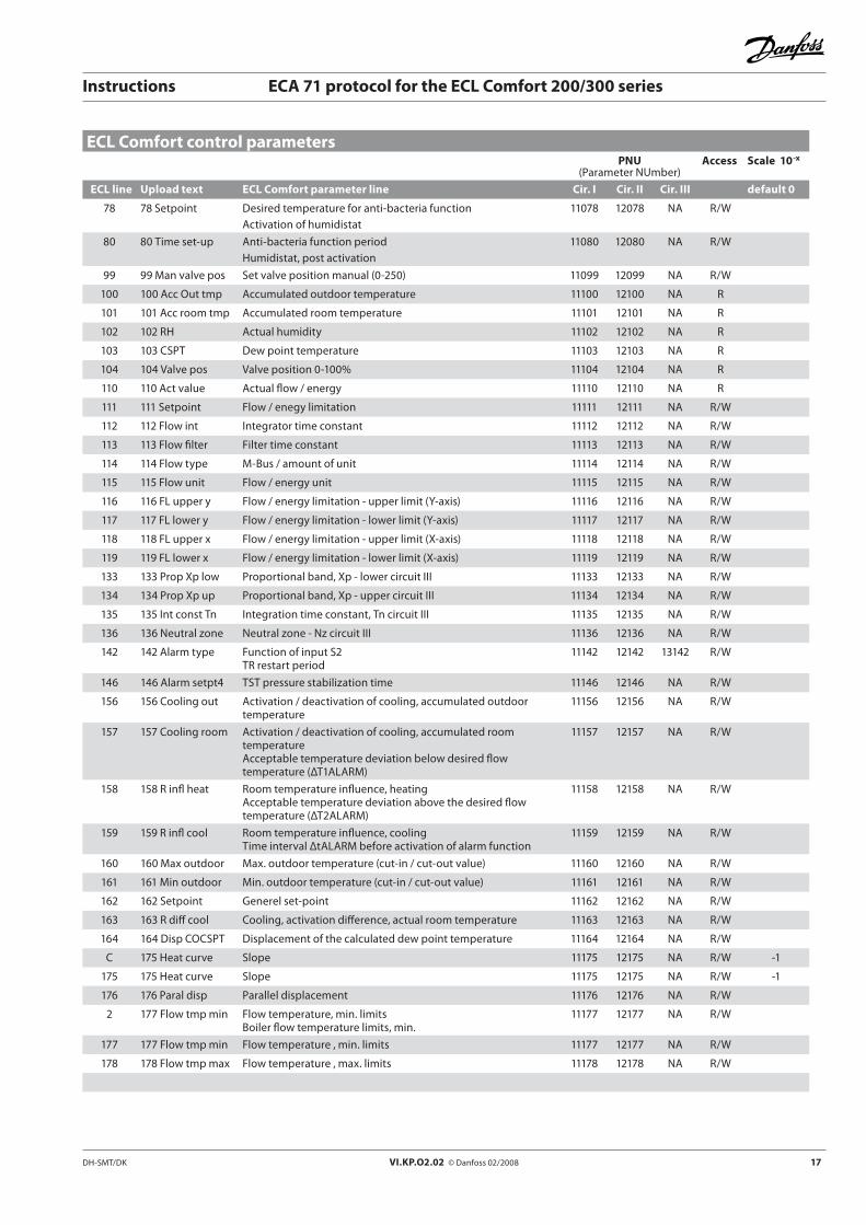
ECL Comfort control parametersPNU
(Parameter NUmber)Access Scale 10-x
ECL line Upload text ECL Comfort parameter line Cir. I Cir. II Cir. III default 0
11 11 Cancel red Setback temperature dependent on outdoor temperature 11011 12011 NA R/W
12 12 Boost Boost 11012 12012 NA R/W
13 13 Ref ramp Reference ramping 11013 12013 NA R/W
14 14 Opt const Optimizing time constant 11014 12014 NA R/W
16 16 Frost lim Frost protection by DHW circulation pump 11016 NA NA R/W
17 17 Tref f back Influence on desired flow temperatureTemperature reference feedback
11017 NA NA R/W
18 18 Ball tmp Balance temperature 11018 NA NA R/W
21 21 Total stop Total stopRelay 1 (R1) function related to room temperature
11021 12021 NA R/W
30 30 RTL const Return temperature limitationLimitation temperature, sensor S4
11030 12030 NA R/W
31 31 RTL upper X Return temperature limitation - upper limit (X-axis) 11031 12031 NA R/W
32 32 RTL upper Y Return temperature limitation - upper limit (Y-axis) 11032 12032 NA R/W
33 33 RTL lower X Return temperature limitation - lower limit (X-axis) 11033 12033 NA R/W
34 34 RTL lower Y Return temperature limitation - lower limit (Y-axis) 11034 12034 NA R/W
35 35 RTI max Limitation temperature influence, max. 11035 12035 NA R/W -1
36 36 RTI min Limitation temperature influence, min. 11036 12036 NA R/W -1
37 37 Adaptive RTL Time constant for temperature limitationTime constant for return temperature limitation
11037 12037 NA R/W
44 44 Max DHW load Max. DHW charging time 11044 12044 NA R/W
45 45 Max heat time DHW charging deactivation timeCompensation of heat loss in circulation circuit
11045 12045 NA R/W
53 53 PI ref DHW Desired flow temperature, DHW charging 11053 12053 NA R/W
57 57 Comp infl min Temperature influence by S4, sliding frost protectionSurface temperature influence during cooling
11057 12057 NA R/W -1
58 58 Comp Compensation 11058 12058 NA R/W
59 59 Adaptive comp Adaptive function of compensation 11059 12059 NA
60 60 Comp limit Compensation temperature, 1. pointSurface temperature limitation during heatingMax. slab temperature limitation
11060 12060 NA R/W
61 61 Comp infl max Compensation temperature influence, 1. point, max. limitation 11061 12061 NA R/W -1
62 62 Comp infl min Influence at max. slab temperatureCompensation temperature influence, 1. point, min. limitationSurface temperature influence during heating
11062 12062 NA R/W -1
63 63 Adaptive comp Time constant, compensation temperatureAdaptive function of max. slab temperature limitationAdaptation of the surface temperature limitation
11063 12063 NA R/W
64 64 Comp limit Compensation temperature, 2. pointMin. slab temperature limitationFlow temperature, max. limitation during heating (thermostatic function)
11064 12064 NA R/W
65 65 Comp infl max Compensation temperature influence, 2. point, max. limitationInfluence at min. slab temperature
11065 12065 NA R/W -1
66 66 Comp infl min Compensation temperature influence, 2. point, min. limitation 11066 12066 NA R/W -1
67 67 Adaptive comp Adaptive function of min. slab temperature limitationAdaptive function of S2 flow temperature during DHW charging
11067 12067 NA R/W
DH-SMT/DK VI.KP.O2.02 © Danfoss 02/2008 17
Instructions ECA 71 protocol for the ECL Comfort 200/300 series
78 78 Setpoint Desired temperature for anti-bacteria functionActivation of humidistat
11078 12078 NA R/W
80 80 Time set-up Anti-bacteria function periodHumidistat, post activation
11080 12080 NA R/W
99 99 Man valve pos Set valve position manual (0-250) 11099 12099 NA R/W
100 100 Acc Out tmp Accumulated outdoor temperature 11100 12100 NA R
101 101 Acc room tmp Accumulated room temperature 11101 12101 NA R
102 102 RH Actual humidity 11102 12102 NA R
103 103 CSPT Dew point temperature 11103 12103 NA R
104 104 Valve pos Valve position 0-100% 11104 12104 NA R
110 110 Act value Actual flow / energy 11110 12110 NA R
111 111 Setpoint Flow / enegy limitation 11111 12111 NA R/W
112 112 Flow int Integrator time constant 11112 12112 NA R/W
113 113 Flow filter Filter time constant 11113 12113 NA R/W
114 114 Flow type M-Bus / amount of unit 11114 12114 NA R/W
115 115 Flow unit Flow / energy unit 11115 12115 NA R/W
116 116 FL upper y Flow / energy limitation - upper limit (Y-axis) 11116 12116 NA R/W
117 117 FL lower y Flow / energy limitation - lower limit (Y-axis) 11117 12117 NA R/W
118 118 FL upper x Flow / energy limitation - upper limit (X-axis) 11118 12118 NA R/W
119 119 FL lower x Flow / energy limitation - lower limit (X-axis) 11119 12119 NA R/W
133 133 Prop Xp low Proportional band, Xp - lower circuit III 11133 12133 NA R/W
134 134 Prop Xp up Proportional band, Xp - upper circuit III 11134 12134 NA R/W
135 135 Int const Tn Integration time constant, Tn circuit III 11135 12135 NA R/W
136 136 Neutral zone Neutral zone - Nz circuit III 11136 12136 NA R/W
142 142 Alarm type Function of input S2TR restart period
11142 12142 13142 R/W
146 146 Alarm setpt4 TST pressure stabilization time 11146 12146 NA R/W
156 156 Cooling out Activation / deactivation of cooling, accumulated outdoor temperature
11156 12156 NA R/W
157 157 Cooling room Activation / deactivation of cooling, accumulated room temperatureAcceptable temperature deviation below desired flow temperature (ΔT1ALARM)
11157 12157 NA R/W
158 158 R infl heat Room temperature influence, heatingAcceptable temperature deviation above the desired flow temperature (ΔT2ALARM)
11158 12158 NA R/W
159 159 R infl cool Room temperature influence, coolingTime interval ΔtALARM before activation of alarm function
11159 12159 NA R/W
160 160 Max outdoor Max. outdoor temperature (cut-in / cut-out value) 11160 12160 NA R/W
161 161 Min outdoor Min. outdoor temperature (cut-in / cut-out value) 11161 12161 NA R/W
162 162 Setpoint Generel set-point 11162 12162 NA R/W
163 163 R diff cool Cooling, activation difference, actual room temperature 11163 12163 NA R/W
164 164 Disp COCSPT Displacement of the calculated dew point temperature 11164 12164 NA R/W
C 175 Heat curve Slope 11175 12175 NA R/W -1
175 175 Heat curve Slope 11175 12175 NA R/W -1
176 176 Paral disp Parallel displacement 11176 12176 NA R/W
2 177 Flow tmp min Flow temperature, min. limitsBoiler flow temperature limits, min.
11177 12177 NA R/W
177 177 Flow tmp min Flow temperature , min. limits 11177 12177 NA R/W
178 178 Flow tmp max Flow temperature , max. limits 11178 12178 NA R/W
ECL Comfort control parametersPNU
(Parameter NUmber)Access Scale 10-x
ECL line Upload text ECL Comfort parameter line Cir. I Cir. II Cir. III default 0

18 VI.KP.O2.02 © Danfoss 02/2008 DH-SMT/DK
Instructions ECA 71 protocol for the ECL Comfort 200/300 series
1 179 Heat cut out Limit for heating cut-out 11179 12179 NA R/W
179 179 Heat cut out Limit for heating cut-out 11179 12179 NA R/W
A 180 Day setpt Desired room temperature - comfort 11180 12180 NA R/W
180 180 Day setpt Desired room temperature - comfort 11180 12180 NA R/W
181 181 Night setpt Desired room temperature - setback 11181 12181 NA R/W
B 182 Room inf max Room temperature influence - max 11182 12182 NA R/W -1
3 182 Room inf max Room temperature influence 11182 12182 NA R/W -1
182 182 Room inf max Room temperature influence - max 11182 12182 NA R/W -1
183 183 Room inf min Room temperature influence - minRoom temperature influence
11183 12183 NA R/W -1
4 184 Prob Xp Proportional band, Xp 11184 12184 NA R/W
184 184 Prob Xp Proportional band - Xp 11184 12184 NA R/W
5 185 Int const Tn Integration time constant, Tn 11185 12185 NA R/W
185 185 Int const Tn Integration constant - Tn 11185 12185 NA R/W
6 186 Run time Running time of the motorized control valve 11186 12186 NA R/W
186 186 Run time Running time of the motorized control valve 11186 12186 NA R/W
7 187 Neutral zone Neutral zone, Nz 11187 12187 NA R/W
187 187 Neutral zone Neutral zone - Nz 11187 12187 NA R/W
188 188 BEM BEM-functionBoiler temperature difference
11188 NA NA R/W
190 190 DHW day Desired DHW temperature - comfort 11190 12190 13190 R/W
191 191 DHW night Desired DHW temperature - setback 11191 12191 13191 R/W
192 192 DHW diff DHW temperature difference 11192 12192 NA R/W
193 193 Charging tmp Charging temperature difference 11193 12193 NA R/W
194 194 Diff1 cutout Cut-out temperature difference - (lower sensor)*Temperature difference at DHW charging, cut-out temperature difference - lower tank temperature sensor
11194 12194 NA R/W
195 195 Diff2 cutin Cut-in temperature difference - (upper sensor)*Temperature at DHW charging, cut-in temperature difference - upper tank temperature sensor
11195 12195 NA R/W
198 198 Summertime Daylight saving time changeover 11198 NA NA R/W
ECL Comfort control parametersPNU
(Parameter NUmber)Access Scale 10-x
ECL line Upload text ECL Comfort parameter line Cir. I Cir. II Cir. III default 0
Minutes step 1 Minutes step 1 11213 12213 NA R
Minutes step 2 Minutes step 2 11214 12214 NA R
Hours step 1 Hours step 1 11215 12215 NA R
Hours step 2 Hours step 2 11216 12216 NA R
Cutin step1 Cut in step 1 11242 12242 NA R
Cutin step2 Cut in step 2 11243 12243 NA R
Cutin 1000 step1 Cut in * 1000 step 1 11245 12245 NA R
Cutin 1000 step2 Cut in * 1000 step 2 11246 12246 NA R
Time countersPNU
(Parameter NUmber)Access Scale 10-x
ECL line Upload text ECL Comfort parameter Cir. I Cir. II Cir. III default 0

DH-SMT/DK VI.KP.O2.02 © Danfoss 02/2008 1�
Instructions ECA 71 protocol for the ECL Comfort 200/300 series
Sensors and referencesPNU
(Parameter NUmber)Access Scale 10-x
ECL line Upload text ECL Comfort parameter Cir. I Cir. II Cir. III default 0
S1 sensor S1 sensor 11201 NA NA R/W -1
S2 sensor S2 sensor 11202 12202 13202 R -1
S3 sensor S3 sensor 11203 12203 13203 R -1
S4 sensor S4 sensor 11204 12204 13204 R -1
S5 sensor S5 sensor 11205 12205 13205 R -1
S6 sensor S6 sensor 11206 12206 13206 R -1
Room temp Room temperature 11211 12211 NA R -1
Minutes step 1 Minutes step 1 11213 12213 NA R -1
Minutes step 2 Minutes step 2 11214 12214 NA R
Hours step 1 Hours step 1 11215 12215 NA R
Hours step 2 Hours step 2 11216 12216 NA R
1000 h step 1 Hours * 1000 step 1 11218 12218 NA R
1000 h step 2 Hours * 1000 step 2 11219 12219 NA R
NA Relative humidity 11220 12220 NA R
S7 sensor S7 options sensor 11221 12221 13221 R -1
S8 sensor S8 options sensor 11222 12222 13222 R -1
S9 sensor S9 options sensor 11223 12223 13223 R -1
S10 sensor S10 options sensor 11224 12224 13224 R -1
S1 reference S1 sensor 1 reference 11228 12228 13228 R -1
S2 reference S2 sensor 2 reference 11229 12229 13229 R -1
S3 reference S3 sensor 3 reference 11230 12230 13230 R -1
S4 reference S4 sensor 4 reference 11231 12231 13231 R -1
S5 reference S5 sensor 5 reference 11232 12232 13232 R -1
S6 reference S6 sensor 6 reference 11233 12233 13233 R -1
Cutin step1 Cut in step 1 11242 12242 NA R
Cutin step2 Cut in step 2 11243 12243 NA R
Cutin 1000 step1 Cut in * 1000 step 1 11245 12245 NA R
Cutin 1000 step2 Cut in * 1000 step 2 11246 12246 NA R
S7 reference S7 sensor reference 11248 12248 13248 R -1
S8 reference S8 sensor reference 11249 12249 13249 R -1
S9 reference S9 sensor reference 11250 12250 13250 R -1
S10 reference S10 sensor reference 11251 12251 13251 R -1

20 VI.KP.O2.02 © Danfoss 02/2008 DH-SMT/DK
Instructions ECA 71 protocol for the ECL Comfort 200/300 series
Output statusPNU
(Parameter NUmber)Access Scale 10-x
ECL line Upload text ECL Comfort parameter Cir. I Cir. II Cir. III default 0
Relay 1 Relay 1 status 4001 NA NA R/W
Relay 2 Relay 2 status 4002 NA NA R/W
Relay 3 Relay 3 status 4003 NA NA R/W
Relay 4 Relay 4 status 4004 NA NA R
Relay 5 Relay 5 status 4005 NA NA R
Triac 1 Triac 1 status 4101 NA NA R/W
Triac 2 Triac 2 status 4102 NA NA R/W
Triac 3 Triac 3 status 4103 NA NA R/W
Triac 4 Triac 4 status 4104 NA NA R/W
Alarm word Alarm word 4110 NA NA R
Controller modePNU
(Parameter NUmber)Access Scale 10-x
ECL line Upload text ECL Comfort parameter Cir. I Cir. II Cir. III default 0
Cir 1 mode Circuit 1 mode 4201 NA NA R/W
Cir 2 mode Circuit 2 mode 4202 NA NA R/W
Cir 3 mode Circuit 3 mode 4203 NA NA R/W
Cir 1 status Circuit 1 status 4211 NA NA R
Cir 2 status Circuit 2 status 4212 NA NA R
Cir 3 status Circuit 3 status 4213 NA NA R

DH-SMT/DK VI.KP.O2.02 © Danfoss 02/2008 21
Instructions ECA 71 protocol for the ECL Comfort 200/300 series
SchedulesPNU
(Parameter NUmber)Access Scale 10-x
ECL line Upload text ECL Comfort parameter line Cir. I Cir. II Cir. III default 0
Active Schedule Active Schedule (X-value Schedule) 1100 NA NA R/W
Monday P1 ON Schedule Monday circuit X period 1 start 1110 NA NA R/W
Monday P1 OFF Schedule Monday circuit X period 1 stop 1111 NA NA R/W
Monday P2 ON Schedule Monday circuit X period 2 start 1112 NA NA R/W
Monday P2 OFF Schedule Monday circuit X period 2 stop 1113 NA NA R/W
Monday P3 ON Schedule Monday circuit X period 3 start 1114 NA NA R/W
Monday P3 OFF Schedule Monday circuit X period 3 stop 1115 NA NA R/W
Tuesday P1 ON Schedule Tuesday circuit X period 1 start 1120 NA NA R/W
Tuesday P1 OFF Schedule Tuesday circuit X period 1 stop 1121 NA NA R/W
Tuesday P2 ON Schedule Tuesday circuit X period 2 start 1122 NA NA R/W
Tuesday P2 OFF Schedule Tuesday circuit X period 2 stop 1123 NA NA R/W
Tuesday P3 ON Schedule Tuesday circuit X period 3 start 1124 NA NA R/W
Tuesday P3 OFF Schedule Tuesday circuit X period 3 stop 1125 NA NA R/W
Wednesday P1 ON Schedule Wednesday circuit X period 1 start 1130 NA NA R/W
Wednesday P1 OFF Schedule Wednesday circuit X period 1 stop 1131 NA NA R/W
Wednesday P2 ON Schedule Wednesday circuit X period 2 start 1132 NA NA R/W
Wednesday P2 OFF Schedule Wednesday circuit X period 2 stop 1133 NA NA R/W
Wednesday P3 ON Schedule Wednesday circuit X period 3 start 1134 NA NA R/W
Wednesday P3 OFF Schedule Wednesday circuit X period 3 stop 1135 NA NA R/W
Thursday P1 ON Schedule Thursday circuit X period 1 start 1140 NA NA R/W
Thursday P1 OFF Schedule Thursday circuit X period 1 stop 1141 NA NA R/W
Thursday P2 ON Schedule Thursday circuit X period 2 start 1142 NA NA R/W
Thursday P2 OFF Schedule Thursday circuit X period 2 stop 1143 NA NA R/W
Thursday P3 ON Schedule Thursday circuit X period 3 start 1144 NA NA R/W
Thursday P3 OFF Schedule Thursday circuit X period 3 stop 1145 NA NA R/W
Friday P1 ON Schedule Friday circuit X period 1 start 1150 NA NA R/W
Friday P1 OFF Schedule Friday circuit X period 1 stop 1151 NA NA R/W
Friday P2 ON Schedule Friday circuit X period 2 start 1152 NA NA R/W
Friday P2 OFF Schedule Friday circuit X period 2 stop 1153 NA NA R/W
Friday P3 ON Schedule Friday circuit X period 3 start 1154 NA NA R/W
Friday P3 OFF Schedule Friday circuit X period 3 stop 1155 NA NA R/W
Saturday P1 ON Schedule Saturday circuit X period 1 start 1160 NA NA R/W
Saturday P1 OFF Schedule Saturday circuit X period 1 stop 1161 NA NA R/W
Saturday P2 ON Schedule Saturday circuit X period 2 start 1162 NA NA R/W
Saturday P2 OFF Schedule Saturday circuit X period 2 stop 1163 NA NA R/W
Saturday P3 ON Schedule Saturday circuit X period 3 start 1164 NA NA R/W
Saturday P3 OFF Schedule Saturday circuit X period 3 stop 1165 NA NA R/W
Sunday P1 ON Schedule Sunday circuit X period 1 start 1170 NA NA R/W
Sunday P1 OFF Schedule Sunday circuit X period 1 stop 1171 NA NA R/W
Sunday P2 ON Schedule Sunday circuit X period 2 start 1172 NA NA R/W
Sunday P2 OFF Schedule Sunday circuit X period 2 stop 1173 NA NA R/W
Sunday P3 ON Schedule Sunday circuit X period 3 start 1174 NA NA R/W
Sunday P3 OFF Schedule Sunday circuit X period 3 stop 1175 NA NA R/W

22 VI.KP.O2.02 © Danfoss 02/2008 DH-SMT/DK
Instructions ECA 71 protocol for the ECL Comfort 200/300 series
M-Bus data from heat meterPNU
(Parameter NUmber)Access Scale 10-x
ECL line Upload text ECL Comfort parameter line Cir. I Cir. II Cir. III default 0
Flow 1 M-Bus slave 1 actual flow value 4501 NA NA R -1
Flow unit 1 M-Bus slave 1 actual flow unit 4502 NA NA R
Volumen 1 M-Bus slave 1 accumulated volumen value 4503 NA NA R
Volumen unit 1 M-Bus slave 1 accumulated volumen unit 4504 NA NA R/W
Power 1 M-Bus slave 1 actual power value 4505 NA NA R -1
Power unit 1 M-Bus slave 1 actual power unit 4506 NA NA R
Energy 1 M-Bus slave 1 accumulated energy value 4507 NA NA R
Energy unit 1 M-Bus slave 1 accumulated energy unit 4508 NA NA R/W
Flow temp 1 M-Bus slave 1 flow temperature 4509 NA NA R -1
Return temp 1 M-Bus slave 1 return temperature 4510 NA NA R -1
Flow 2 M-Bus slave 2 actual flow value 4521 NA NA R -1
Flow unit 2 M-Bus slave 2 actual flow unit 4522 NA NA R
Volumen 2 M-Bus slave 2 accumulated volumen value 4523 NA NA R
Volumen unit 2 M-Bus slave 2 accumulated volumen unit 4524 NA NA R/W
Power 2 M-Bus slave 2 actual power value 4525 NA NA R -1
Power unit 2 M-Bus slave 2 actual power unit 4526 NA NA R
Energy 2 M-Bus slave 2 accumulated energy value 4527 NA NA R
Energy unit 2 M-Bus slave 2 accumulated energy unit 4528 NA NA R/W
Flow temp 2 M-Bus slave 2 flow temperature 4529 NA NA R -1
Return temp 2 M-Bus slave 2 return temperature 4530 NA NA R -1
Data from ECA 83 and ECA 88PNU
(Parameter NUmber)Access Scale 10-x
ECL line Upload text ECL Comfort parameter line Cir. I Cir. II Cir. III default 0
Analog 1 Analog input 1 (ECA 83) 4601 NA NA R -1
Analog 2 Analog input 2 (ECA 83) 4602 NA NA R -1
NA Accumulated pulse circuit 1 (high word) 4611 NA NA R/W
NA Accumulated pulse circuit 1 (low word) 4612 NA NA R/W
NA Accumulated pulse circuit 2 (high word) 4613 NA NA R/W
NA Accumulated pulse circuit 2 (low word) 4614 NA NA R/W

DH-SMT/DK VI.KP.O2.02 © Danfoss 02/2008 23
Instructions ECA 71 protocol for the ECL Comfort 200/300 series
M-Bus high resolution data from heat meterPNU
(Parameter NUmber)Access Scale 10-x
ECL line Upload text ECL Comfort parameter line Cir. I Cir. II Cir. III default 0
NA M-Bus slave 1 high res. Accumulated volumen unit 4620 NA NA R/W
NA M-Bus slave 1 high res. Accumulated volumen (high word) 4621 NA NA R
NA M-Bus slave 1 high res. Accumulated volumen (low word) 4622 NA NA R
NA M-Bus slave 1 high res. Accumulated energy unit 4623 NA NA R/W
NA M-Bus slave 1 high res. Accumulated energy (high word) 4624 NA NA R
NA M-Bus slave 1 high res. Accumulated energy (low word) 4625 NA NA R
NA M-Bus slave 1 high res. Accumulated volumen unit 4626 NA NA R/W
NA M-Bus slave 2 high res. Accumulated volumen (high word) 4627 NA NA R
NA M-Bus slave 2 high res. Accumulated volumen (low word) 4628 NA NA R
NA M-Bus slave 1 high res. Accumulated energy unit 4629 NA NA R/W
NA M-Bus slave 2 high res. Accumulated energy (high word) 4630 NA NA R
NA M-Bus slave 2 high res. Accumulated energy (low word) 4631 NA NA R
Time, date and systemPNU
(Parameter NUmber)Access Scale 10-x
ECL line Upload text ECL Comfort parameter line Cir. I Cir. II Cir. III default 0
Hour Hour 64045 R/W
Minutes Min 64046 R/W
DayMonth Date 64047 R/W
Month Month 64048 R/W
Year Year 64049 R/W
ECL SW ver ECL Comfort software version 2003 R -1
Manual control Manual control 2004 R/W
ECL net adr ECL Comfort network address 2008 R
ECL Code No ECL Comfort Code number 2011 R
ECA SW ver Modbus / LON software version 2012 R -1
NA ECA module SW version 2103 R
NA ECA module HW version/revision 2104 R
NA ECL Comfort SW version 2105 R
NA ECL Comfort HW Type 2106 R
NA ECL Comfort Hardware version/revision 2107 R
Explanations:
ECL line The parameter line according to the ECL Comfort user interface / instructions
Upload text Text to be uploaded from the ECA 71 which is used in the ServiceTool
ECL Comfort parameter line Description of the parameter
Cir. Circuit in the ECL Comfort controller
Access Read / write permission
Scale Decimal numbers cannot be send so the sent value is divided by 10-1. Example: The slope has the scale -1. Value read = 18. 18 x 10 -1 = 1.8
VI.KP.O2.02 © Danfoss 02/2008 DH-SMT/DK
Instructions ECA 71 protocol for the ECL Comfort 200/300 series
Danfoss can accept no responsibility for possible errors in catalogues, brochures and other printed material. Danfoss reserves the right to alter its products without notice. This also applies to products already on order provided that such alterations can be made without subsequential changes being necessary in speci�cations already agreed.All trademarks in this material are property of the respective companies. Danfoss and the Danfoss logotype are trademarks of Danfoss A/S. All rights reserved.
*087R9775**VIKPO202*