EC145 Technical Data
74
EU ROCOPTER EC145 Technical Data 145 08.101.01 E
Transcript of EC145 Technical Data

Eurocopter reserves the right to make configuration and data changes at any time without notice. The facts and figures contained in this document and expressed in good faith do not constitute any offer or contract with Eurocopter
E U R O C O P T E R
EC145
Technical Data
145 08.101.01 E
C
M
J
CM
MJ
CJ
CMJ
N
Base_EC145.ai 12/02/2007 08:36:45Base_EC145.ai 12/02/2007 08:36:45

Technical Data
The data set forth in this document are general in nature and for information purposes only. For performance data and operating limitations, reference must be made to the approved flight manual and all appropriate documents.
145.08.101.01 E This document is the property of EUROCOPTER; no part of it shall be reproduced or transmitted without the express prior written authorization of EUROCOPTER and its contents shall not be disclosed. © eurocopter - 01/2006
Blank

Technical Data
The data set forth in this document are general in nature and for information purposes only. For performance data and operating limitations, reference must be made to the approved flight manual and all appropriate documents.
145.08.101.01 E 1 This document is the property of EUROCOPTER; no part of it shall be reproduced or transmitted without the express prior written authorization of EUROCOPTER and its contents shall not be disclosed. © eurocopter - 01/2006
Contents 1. Foreword....................................................................................................................................... 3 2. General characteristics................................................................................................................. 6
2.1. Exterior dimensions .................................................................................................................. 6 2.2. Internal dimensions................................................................................................................... 7 2.3. Possible cabin arrangement (seats & equipment as option) .................................................... 7 2.4. Weight ....................................................................................................................................... 8 2.5. Fuel Capacities ......................................................................................................................... 8 2.6. Engines: 2 Turbomeca turbine engines – ARRIEL 1E2............................................................ 8 2.7. Main transmission ..................................................................................................................... 8
3. Baseline aircraft definition .......................................................................................................... 10 4. Basic configuration choice.......................................................................................................... 12
4.1. VFR packages, based on Avionics Solutions A1 and A2 ....................................................... 14 4.2. Dual Pilot or Single/Dual Pilot IFR, based on Avionics Sol. B1 and B2.................................. 20 4.3. Dual Pilot or Single/Dual Pilot IFR with Dual FMS/NMS (Av. Sol. B3) ................................... 26 4.4. Single Pilot IFR, based on Avionics Solution C ...................................................................... 30 4.5. Typical IFR antenna layout ..................................................................................................... 34
5. Cabin arrangement..................................................................................................................... 35 5.1. Passenger transport................................................................................................................ 35 5.2. Stylence / VIP passenger transport ........................................................................................ 36 5.3. EMS ........................................................................................................................................ 38
6. Optional equipment..................................................................................................................... 40 6.1. Further available equipment ................................................................................................... 40 6.2. Avionics................................................................................................................................... 44 6.3. Offshore .................................................................................................................................. 46
7. Table of constraints .................................................................................................................... 47 7.1. General Checklist for Incompatibilities.................................................................................... 47 7.2. Legend and constraints chart.................................................................................................. 48
8. Main performance....................................................................................................................... 50 9. Support information .................................................................................................................... 64
9.1. Assets ..................................................................................................................................... 64 9.2. Inspection Program................................................................................................................. 64 9.3. Main components Time Between Overhaul (TBO) / Service Life Limit (SLL)........................ 66 9.4. Eurocopter Maintenance Support Programs .......................................................................... 67 9.5. Engine Maintenance program................................................................................................. 68 9.6. Training ................................................................................................................................... 69 9.7. Technical publications............................................................................................................. 70 9.8. T.I.P.I. (Technical Information Publication on Internet)........................................................... 70

Technical Data
The data set forth in this document are general in nature and for information purposes only. For performance data and operating limitations, reference must be made to the approved flight manual and all appropriate documents.
145.08.101.01 E 2 This document is the property of EUROCOPTER; no part of it shall be reproduced or transmitted without the express prior written authorization of EUROCOPTER and its contents shall not be disclosed. © eurocopter - 01/2006
Manufacturer’s notes – Attention! Eurocopter’s policy is one of on-going product enhancement which means that alterations in definition, pictures, weights, dimensions or performance may be made at any time without notice being included in those documents that have already been issued. This document cannot thus be taken as an offer or serve as an appendix to a contract without a prior check as to its validity and prior written agreement of EUROCOPTER. The operational or certification regulations, as defined by the local authorities, can make compulsory the installation of some of the equipment or recommended solutions, listed in this document. This list does not claim to cover the whole of the worldwide operational requirements nor the equipment not specifically related to the helicopter (for example: life jacket) or necessary for particular missions (for example: supplemental oxygen). The operator is responsible for ascertaining with his local authorities that the planned configuration of the helicopter complies with regulatory requirements for the area(s) of operations and the type(s) of mission(s) considered. EUROCOPTER, its logo, M’ARMS®, and Stylence® are trade marks of the Eurocopter group.

Technical Data
The data set forth in this document are general in nature and for information purposes only. For performance data and operating limitations, reference must be made to the approved flight manual and all appropriate documents.
145.08.101.01 E 3 This document is the property of EUROCOPTER; no part of it shall be reproduced or transmitted without the express prior written authorization of EUROCOPTER and its contents shall not be disclosed. © eurocopter - 01/2006
1. Foreword
The EC145, certified under the name BK117 C-2, is a twin-engine, multi-purpose helicopter of the 3-4 ton class with up to 11 seats for pilot/s and passengers. It combines Eurocopter’s latest developments, like advanced cockpit design, avionics and sophisticated electrical system with the rugged and proven design elements of the BK117, as for example the rotor system. The EC145’s hingeless rotor system with its monolithic titanium hub (‘System Bölkow’) is proven all over the world. Furthermore, the rotor blades have been improved with respect to higher performance and lower noise and vibration levels. The use of the variable rotor speed and torque matching system (VARTOMS), known from the predecessor model BK117 C-1 has been extended. Besides ameliorating flying comfort, this makes the EC145 the quietest helicopter in its class bringing it to 6.7 dBA below ICAO limits.
In addition to environmental and economical aspects, the rotor system together with high TBO gearbox and airframe components grant for low maintenance costs and on the other hand, high in-service-time of the helicopter due to low scheduled maintenance required.
The EC145 is equipped with two powerful and reliable Turbomeca Arriel 1E2 engines which, in combination with its lifting system, provide outstanding performance and vital power reserves even in one-engine-inoperative (OEI) scenarios. Twin-engine reliability is complemented by a fully separated fuel system, a tandem hydraulic system, dual electrical system and redundant lubrication for the main transmission. Further positive safety aspects of the EC145 are design elements like energy absorbing fuselage and seats, as well as crash resistant fuel cells. The EC145 allows Cat. A operation up to the level of performance class 1 and performance class 2 according to JAR-OPS 3.
A wide range of optional equipment, like emergency floats, rescue hoist, SX16 search light, cargo hook, plus many more is available for the EC145 and can be fitted simultaneously in most cases. Together with its most versatile cabin layout (utility, comfort, corporate, ...), the EC145 is ready to take up all sorts of missions, for example survey, transport, EMS, public service, to name a few.

Technical Data
The data set forth in this document are general in nature and for information purposes only. For performance data and operating limitations, reference must be made to the approved flight manual and all appropriate documents.
145.08.101.01 E 4 This document is the property of EUROCOPTER; no part of it shall be reproduced or transmitted without the express prior written authorization of EUROCOPTER and its contents shall not be disclosed. © eurocopter - 01/2006
Compared to other helicopters in its class, the EC145 offers a significantly larger cabin, featuring:
Excellent outside vision for pilot/s, crew or passengers Roomy cabin with no partitions or protrusions, no center post, no door post Unrivalled side loading (no door posts) and rear loading capability Flat floor all over the cabin area

Technical Data
The data set forth in this document are general in nature and for information purposes only. For performance data and operating limitations, reference must be made to the approved flight manual and all appropriate documents.
145.08.101.01 E 5 This document is the property of EUROCOPTER; no part of it shall be reproduced or transmitted without the express prior written authorization of EUROCOPTER and its contents shall not be disclosed. © eurocopter - 01/2006
The EC145 offers a choice of modern state-of-the-art glass cockpit solutions comprising primary flight displays (PFD) and NAV displays (ND) as well as a central panel display system (CPDS). All LCD screens are well arranged on the instrument panel, easy to read even if viewed from an angle and feature perfect readability in any light conditions. An NVG layout is available as an option. The unique color coding, warning and information concept helps the pilot/s to collect all relevant parameters while suppressing presentation of non-relevant information. Additionally, Eurocopter’s unique first limit indicator (FLI) considerably simplifies engine and torque monitoring. Being relieved from extensive instrument scan without missing vital information, pilots can dedicate more of their attention to the mission.
Latest news / highlights: • In recognition of its capabilities, the EC145 has been selected by the Light Utility Helicopter
(LUH) program of US Army. Sharp production ramp up is in progress. • New Stylence and VIP packages are available on request. • New RDR2000 radar offering a lightweight solution providing weather awareness ahead. • Vector mast moment system indicating the direction of the current mast moment thus
assisting the pilot during slope landings. • Software upgrade of CPDS and AFCS based on customer feedback.
Technical Data
The data set forth in this document are general in nature and for information purposes only. For performance data and operating limitations, reference must be made to the approved flight manual and all appropriate documents.
145.08.101.01 E 6 This document is the property of EUROCOPTER; no part of it shall be reproduced or transmitted without the express prior written authorization of EUROCOPTER and its contents shall not be disclosed. © eurocopter - 01/2006
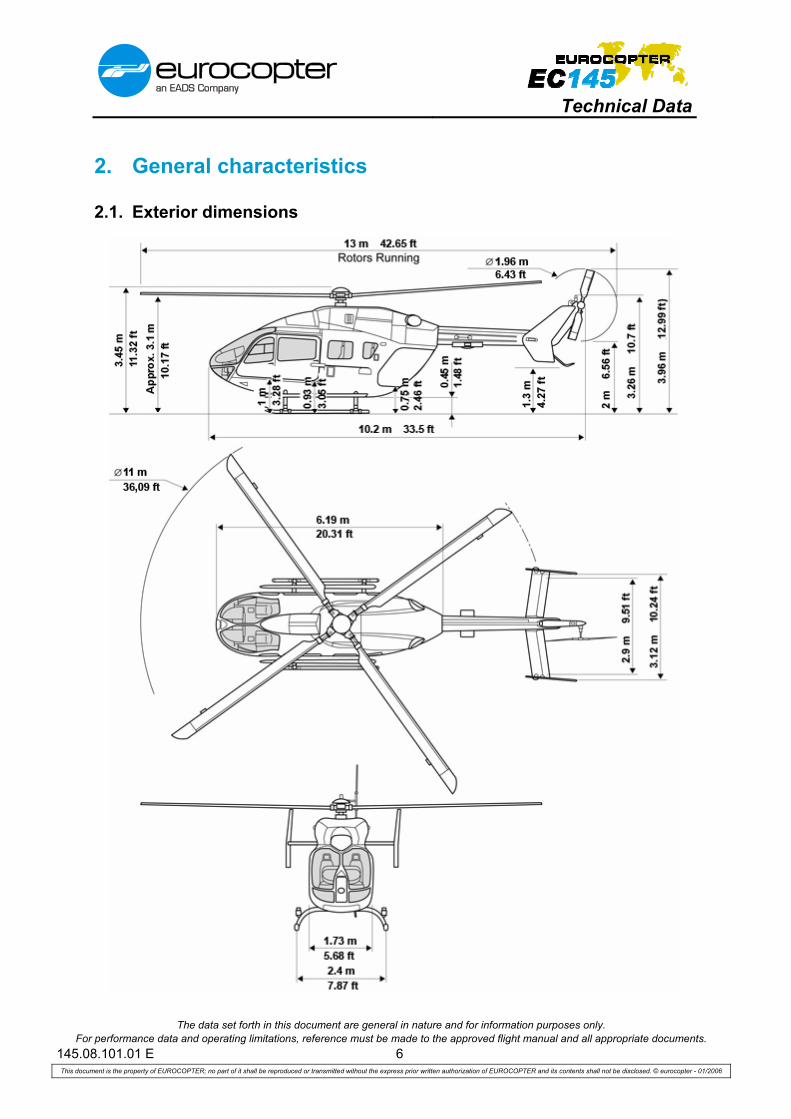
2. General characteristics
2.1. Exterior dimensions

Technical Data
The data set forth in this document are general in nature and for information purposes only. For performance data and operating limitations, reference must be made to the approved flight manual and all appropriate documents.
145.08.101.01 E 7 This document is the property of EUROCOPTER; no part of it shall be reproduced or transmitted without the express prior written authorization of EUROCOPTER and its contents shall not be disclosed. © eurocopter - 01/2006
2.2. Internal dimensions
Floor area Volume
Cabin & baggage compartment (Baggage compartment with 8 seats installed)
4.72 m2
0.84 m2 50.77 ft2
9.07 ft2 6.04 m3
1.32 m3 213.15 ft3
46.72 ft3
Copilot 0.72 m2 7.73 ft2 0.80 m3 28.25 ft3
Pilot (not shaded) 1.09 m2 11.80 ft2 1.24 m3 43.76 ft3
Total (undivided) 5.43 m2 58.50 ft2 6.84 m3 241.40 ft3
Total (incl. pilot station) 6.52 m2 70.30 ft2 8.08 m3 285.16 ft3
2.3. Possible cabin arrangement (seats & equipment as option)
Passenger transport 1 or 2 pilots + up to 8 passengers in club seating configuration (energy absorbing individual seats) + 1.32 m3 baggage / freight
High-density seating 1 or 2 pilots + up to 9 passengers in high-density seating configuration (energy absorbing individual troop seats)
EMS / Casualty evacuation 1 or 2 pilots + up to 2 stretcher patients + up to 3 HEMS crew

Technical Data
The data set forth in this document are general in nature and for information purposes only. For performance data and operating limitations, reference must be made to the approved flight manual and all appropriate documents.
145.08.101.01 E 8 This document is the property of EUROCOPTER; no part of it shall be reproduced or transmitted without the express prior written authorization of EUROCOPTER and its contents shall not be disclosed. © eurocopter - 01/2006
2.4. Weight
Note : margin ± 1.5 % kg lb Empty weight, wet (in standard aircraft configuration) 1,792 3,951 Useful load (for standard aircraft configuration) 1,793 3,953 Pilot 80 176 Payload and / or fuel 1,713 3,777 Maximum take-off weight 3,585 7,903 Maximum take-off weight with external load 3,585 7,903 Sling load (single hook) 1,500 3,307
2.5. Fuel Capacities
Usable Fuel Unusable Fuel Note: Tolerance of fuel figures: ±2% Fuel density used is 0.8 kg / liter. lb kg l lb kg
Main Tank 1307.8 593.2 741.5 7.3 3.3 Supply Tank (left) 104.1 47.2 59.0 6.6 3.0 Supply Tank (right) 118.2 53.6 67.0 6.6 3.0 Total 1530.0 694.0 867.5 20.5 9.3
2.6. Engines: 2 Turbomeca turbine engines – ARRIEL 1E2
Engine ratings
Thermodynamic limits per engine at SL, ISA kW ch shp One Engine Inoperative (OEI), 2.5 min power 574 780 770 One Engine Inoperative (OEI), MCP 550 748 738 Take-Off Power (TOP) 550 748 738 Maximum Continuous Power (MCP) 516 701 692
2.7. Main transmission
Main transmission ratings
Single engine operation kW ch shp 2.5 min OEI-power 1 x 551 1 x 750 1 x 739 Maximum continuous OEI-power 1 x 404 1 x 550 1 x 542
Twin engine operation
Take-Off Power (TOP) 2 x 388 2 x 528 2 x 520 Maximum Continuous Power (MCP) 2 x 316 2 x 430 2 x 424

Technical Data
The data set forth in this document are general in nature and for information purposes only. For performance data and operating limitations, reference must be made to the approved flight manual and all appropriate documents.
145.08.101.01 E 9 This document is the property of EUROCOPTER; no part of it shall be reproduced or transmitted without the express prior written authorization of EUROCOPTER and its contents shall not be disclosed. © eurocopter - 01/2006
Blank

Technical Data
The data set forth in this document are general in nature and for information purposes only. For performance data and operating limitations, reference must be made to the approved flight manual and all appropriate documents.
145.08.100.01 E 10 This document is the property of EUROCOPTER; no part of it shall be reproduced or transmitted without the express prior written authorization of EUROCOPTER and its contents shall not be disclosed. © eurocopter - 01/2006
3. Baseline aircraft definition
GENERAL
Energy absorbing fuselage Tail boom with fixed horizontal stabilizer and two end-
plates Upper deck with fittings for main gearbox, engines,
hydraulic and cooling system Cowlings for main transmission and engines
Skid-type landing gear with skid protectors, capable of taking ground-handling wheels
Long boarding steps, LH and RH Cold weather kit Built-in maintenance steps and grips Exterior painting (single color)
COCKPIT, CABIN AND CARGO COMPARTMENT
One-level cabin and cargo compartment floor with integrated rails
Glazed canopy Two hinged cockpit doors with sliding window Map case in pilot’s door Two wide passenger sliding doors Two rear hinged clam-shell doors Longitudinally adjustable energy absorbing pilot and copilot
seats with head rest and 4-point safety belts with automatic locking system
Cabin boarding grips (LH and RH) Interior paneling with integrated basic sound insulation Flight controls (pilot side) Engine twist grip controls at pilot’s collective pitch lever
Instrument panel with extension on pilot’s side and glare shield
Ram-air for cockpit Electrical ventilating system for cockpit Headset holder in the cockpit, rotatable Portable fire extinguisher Stowage net for first aid kit at the LH rear clam-shell door First aid kit1 Flash light (torch) 4 mobile tie-down rings Slant panel Center console Windscreen wiper for pilot and copilot Door open warning
BASIC INSTRUMENTATION
Central Panel Central Panel Display System (CPDS) consisting of two
LCD displays Cautions and Advisories Display (CAD) with digital
indication of: Caution and advisory information Fuel quantity indication
Vehicle and Engine Management Display (VEMD) with digital indication of: Engine parameters (engine oil pressure, engine oil
temperature) FLI (First Limit Indicator) for TQ, TOT, ΔN1 as
analogue display Main gear box parameters (oil pressure,
oil temperature) Dual amperemeter for generator; amperemeter for
battery Dual voltmeter Outside air temperature (OAT) Mast moment indication
Back-up conventional instruments (2“) Clock Stand-by-horizon Triple (rotor and engines) RPM-indicator
Warning unit: Engine fire warning with fuel emergency shut-off Warning lights Aural warning (for each warning, rotor RPM, fire
warning) Fire extinguishing system warning Master caution light
Main switch panel: DC power control VARTOMS control Start switches
Magnetic compass Air Data Dual pitot static system (electrically heated pitot tube and
static port) 2 ADC MEGHAS sensors
Standard Instruments (single pilot) 2 Air speed indicator (3“) Vertical speed indicator (3“) Encoding altimeter (3“) Artificial horizon (4“) Gyro magnetic heading with horizontal situation ind. (3”)
1 First aid kit complies with German regulation rules 1. DV LuftBO paragraph 5(2). Type of operation, procedures or regulations
may require a different/specific first aid kit. 2 If glass cockpit instrumentation is chosen as optional equipment, these standard instruments are deleted (function included in MEGHAS) and an altimeter (2”) and an airspeed indicator (2”) as back-up instruments are added.
Technical Data
The data set forth in this document are general in nature and for information purposes only. For performance data and operating limitations, reference must be made to the approved flight manual and all appropriate documents.
145.08.100.01 E 11 This document is the property of EUROCOPTER; no part of it shall be reproduced or transmitted without the express prior written authorization of EUROCOPTER and its contents shall not be disclosed. © eurocopter - 01/2006
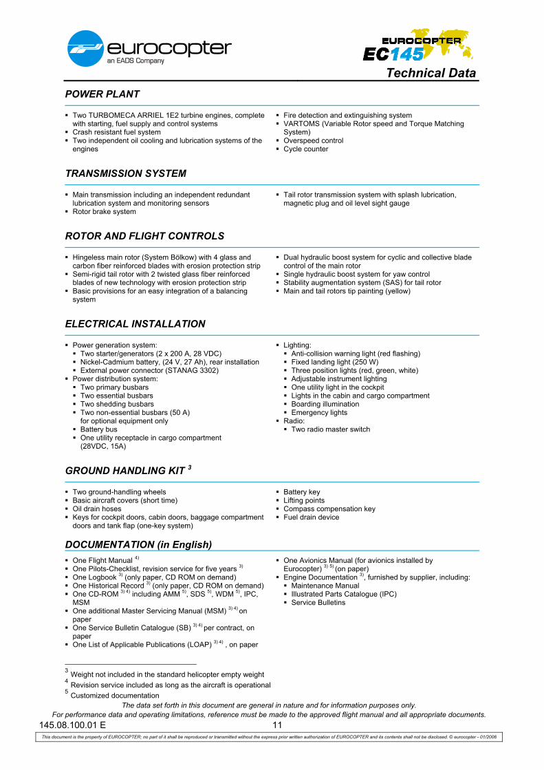
POWER PLANT
Two TURBOMECA ARRIEL 1E2 turbine engines, complete with starting, fuel supply and control systems
Crash resistant fuel system Two independent oil cooling and lubrication systems of the
engines
Fire detection and extinguishing system VARTOMS (Variable Rotor speed and Torque Matching
System) Overspeed control Cycle counter
TRANSMISSION SYSTEM
Main transmission including an independent redundant lubrication system and monitoring sensors
Rotor brake system
Tail rotor transmission system with splash lubrication, magnetic plug and oil level sight gauge
ROTOR AND FLIGHT CONTROLS
Hingeless main rotor (System Bölkow) with 4 glass and carbon fiber reinforced blades with erosion protection strip
Semi-rigid tail rotor with 2 twisted glass fiber reinforced blades of new technology with erosion protection strip
Basic provisions for an easy integration of a balancing system
Dual hydraulic boost system for cyclic and collective blade control of the main rotor
Single hydraulic boost system for yaw control Stability augmentation system (SAS) for tail rotor Main and tail rotors tip painting (yellow)
ELECTRICAL INSTALLATION
Power generation system: Two starter/generators (2 x 200 A, 28 VDC) Nickel-Cadmium battery, (24 V, 27 Ah), rear installation External power connector (STANAG 3302)
Power distribution system: Two primary busbars Two essential busbars Two shedding busbars Two non-essential busbars (50 A)
for optional equipment only Battery bus One utility receptacle in cargo compartment
(28VDC, 15A)
Lighting: Anti-collision warning light (red flashing) Fixed landing light (250 W) Three position lights (red, green, white) Adjustable instrument lighting One utility light in the cockpit Lights in the cabin and cargo compartment Boarding illumination Emergency lights
Radio: Two radio master switch
GROUND HANDLING KIT 3
Two ground-handling wheels Basic aircraft covers (short time) Oil drain hoses Keys for cockpit doors, cabin doors, baggage compartment
doors and tank flap (one-key system)
Battery key Lifting points Compass compensation key Fuel drain device
DOCUMENTATION (in English) One Flight Manual 4) One Pilots-Checklist, revision service for five years 3) One Logbook 3) (only paper, CD ROM on demand) One Historical Record 3) (only paper, CD ROM on demand) One CD-ROM 3) 4) including AMM 5), SDS 5), WDM 5), IPC,
MSM One additional Master Servicing Manual (MSM) 3) 4) on
paper One Service Bulletin Catalogue (SB) 3) 4) per contract, on
paper One List of Applicable Publications (LOAP) 3) 4) , on paper
One Avionics Manual (for avionics installed by Eurocopter) 3) 5) (on paper)
Engine Documentation 3), furnished by supplier, including: Maintenance Manual Illustrated Parts Catalogue (IPC) Service Bulletins
3 Weight not included in the standard helicopter empty weight 4 Revision service included as long as the aircraft is operational 5 Customized documentation
Technical Data
The data set forth in this document are general in nature and for information purposes only. For performance data and operating limitations, reference must be made to the approved flight manual and all appropriate documents.
145.08.101.01 E 12 This document is the property of EUROCOPTER; no part of it shall be reproduced or transmitted without the express prior written authorization of EUROCOPTER and its contents shall not be disclosed. © eurocopter - 01/2006
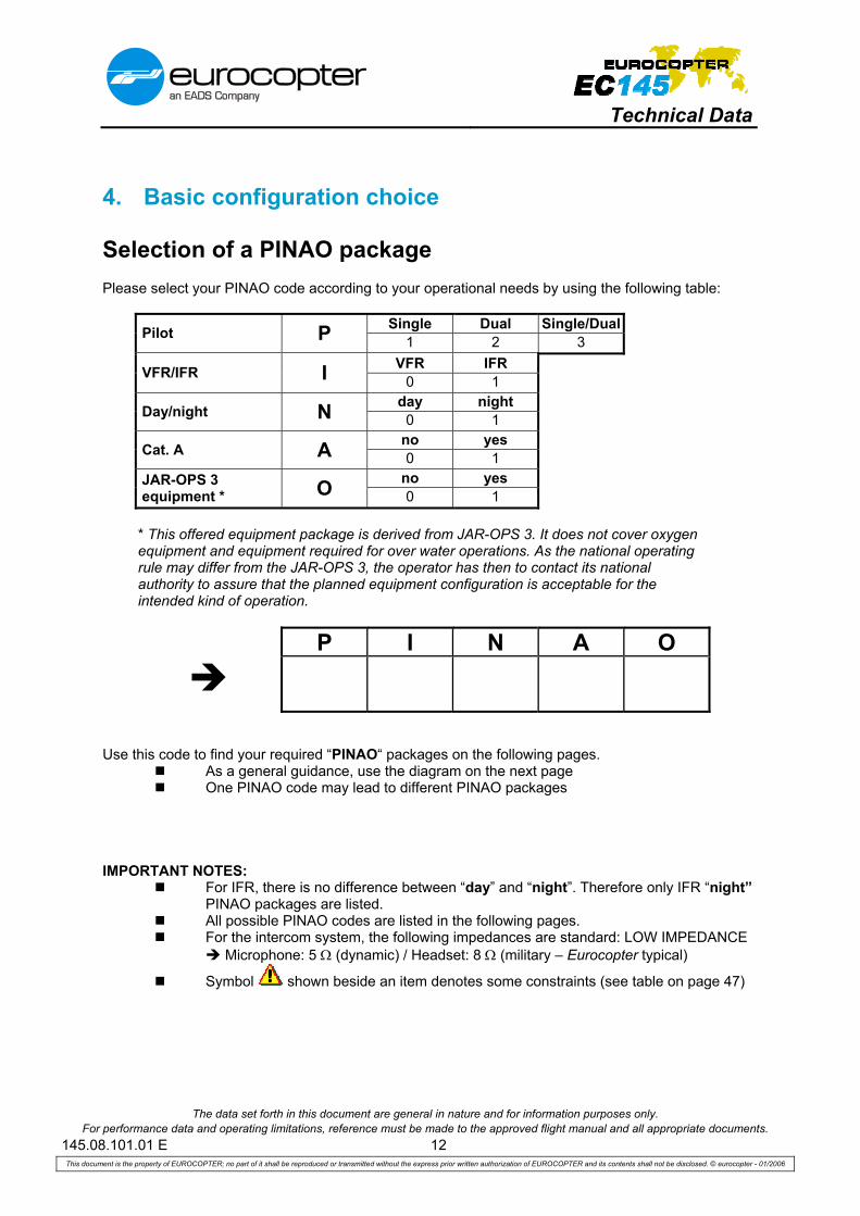
4. Basic configuration choice
Selection of a PINAO package Please select your PINAO code according to your operational needs by using the following table: Single Dual Single/Dual Pilot P 1 2 3 VFR IFR VFR/IFR I 0 1 day night Day/night N 0 1 no yes Cat. A A 0 1 no yes
JAR-OPS 3 equipment * O 0 1
* This offered equipment package is derived from JAR-OPS 3. It does not cover oxygen equipment and equipment required for over water operations. As the national operating rule may differ from the JAR-OPS 3, the operator has then to contact its national authority to assure that the planned equipment configuration is acceptable for the intended kind of operation.
P I N A O
Use this code to find your required “PINAO“ packages on the following pages.
As a general guidance, use the diagram on the next page One PINAO code may lead to different PINAO packages
IMPORTANT NOTES:
For IFR, there is no difference between “day” and “night”. Therefore only IFR “night” PINAO packages are listed.
All possible PINAO codes are listed in the following pages. For the intercom system, the following impedances are standard: LOW IMPEDANCE
Microphone: 5 Ω (dynamic) / Headset: 8 Ω (military – Eurocopter typical)
Symbol shown beside an item denotes some constraints (see table on page 47)

Technical Data
The data set forth in this document are general in nature and for information purposes only. For performance data and operating limitations, reference must be made to the approved flight manual and all appropriate documents.
145.08.101.01 E 13 This document is the property of EUROCOPTER; no part of it shall be reproduced or transmitted without the express prior written authorization of EUROCOPTER and its contents shall not be disclosed. © eurocopter - 01/2006
Use this diagram to find the appropriate Avionics Solution based on your individual PINAO selection.
PINAO
VFR
packages (PINAO codes x0xxx)
IFR packages
(PINAO codes x1xxx)
MEGHAS / FCDS
Glass Cockpit
MEGHAS / FCDS Glass Cockpit
Single/Dual Pilot VFR (PINAO codes 10xxx or
20xxx are included in 30xxx)
Single/Dual Pilot IFR (PINAO codes 31xxx
including 21xxx)
Single Pilot IFR (single sided)
(PINAO codes 11xxx)
Avionics Solution A1 or A2 (see page 14)
Avionics Solution B1 or B2 (see page 20)
or Avionics Solution B3
(see page 26)
Avionics Solution C (see page 30)
Technical Data
The data set forth in this document are general in nature and for information purposes only. For performance data and operating limitations, reference must be made to the approved flight manual and all appropriate documents.
145.08.101.01 E 14 This document is the property of EUROCOPTER; no part of it shall be reproduced or transmitted without the express prior written authorization of EUROCOPTER and its contents shall not be disclosed. © eurocopter - 01/2006
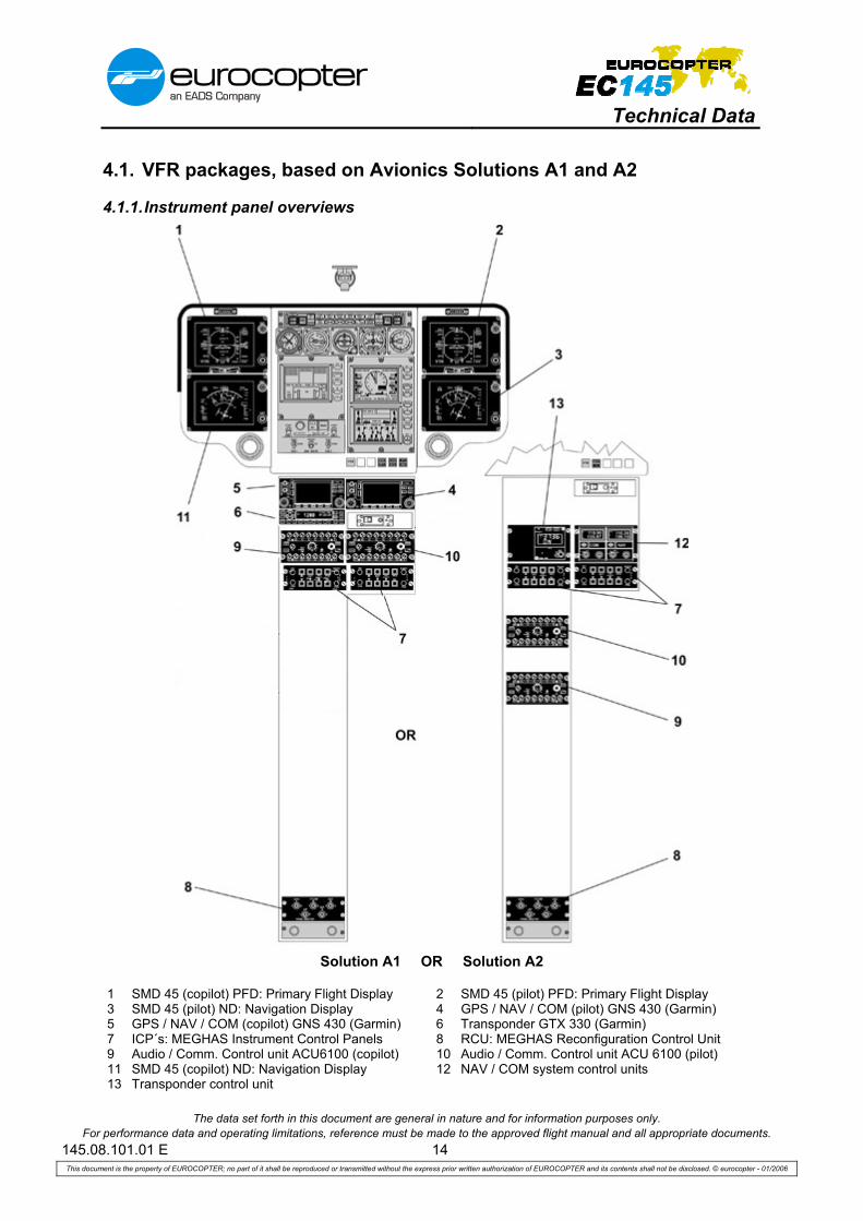
4.1. VFR packages, based on Avionics Solutions A1 and A2
4.1.1. Instrument panel overviews
Solution A1 OR Solution A2
1 SMD 45 (copilot) PFD: Primary Flight Display 2 SMD 45 (pilot) PFD: Primary Flight Display 3 SMD 45 (pilot) ND: Navigation Display 4 GPS / NAV / COM (pilot) GNS 430 (Garmin) 5 GPS / NAV / COM (copilot) GNS 430 (Garmin) 6 Transponder GTX 330 (Garmin) 7 ICP´s: MEGHAS Instrument Control Panels 8 RCU: MEGHAS Reconfiguration Control Unit 9 Audio / Comm. Control unit ACU6100 (copilot) 10 Audio / Comm. Control unit ACU 6100 (pilot) 11 SMD 45 (copilot) ND: Navigation Display 12 NAV / COM system control units 13 Transponder control unit

Technical Data
The data set forth in this document are general in nature and for information purposes only. For performance data and operating limitations, reference must be made to the approved flight manual and all appropriate documents.
145.08.101.01 E 15 This document is the property of EUROCOPTER; no part of it shall be reproduced or transmitted without the express prior written authorization of EUROCOPTER and its contents shall not be disclosed. © eurocopter - 01/2006
4.1.2. Contents of Avionics Solution A1
Document reference
Commercial reference Title
- B2300-004-00 Avionics Solution A1, consisting of:
Intercom System
08-16054-E B2341-190-01 Audio/Comm. Control system 2 x ACU 6100, pilot and copilot, and Remote Electronic Unit REU 6100 (Becker)
08-16054-E B2341-293-01 IC amplifier IC 3100-4-01 (Becker)
Transponder
08-22031-C B2325-092-00 Transponder (Mode S) GTX 330 (Garmin)
GPS/NAV/COM
08-43026-C B3442-092-00 GPS/NAV/COM GNS 430 (Garmin), pilot, interfaced with FCDS
08-43026-C B3442-091-00 GPS/NAV/COM GNS 430 (Garmin), copilot, VOR/ILS interfaced with FCDS, GPS stand alone
Display system
08-65005-C B3161-090-09 MEGHAS – Flight Control Display System (FCDS) Dual (4xSMD45)
Miscellaneous
- B0000-150-04 Avionics Solution A1 interconnection / wiring

Technical Data
The data set forth in this document are general in nature and for information purposes only. For performance data and operating limitations, reference must be made to the approved flight manual and all appropriate documents.
145.08.101.01 E 16 This document is the property of EUROCOPTER; no part of it shall be reproduced or transmitted without the express prior written authorization of EUROCOPTER and its contents shall not be disclosed. © eurocopter - 01/2006
4.1.3. Contents of Avionics Solution A2
Document reference
Commercial reference Title
- B2300-001-00 Avionics Solution A2, consisting of:
VHF AM/COM
08-11026-B B2313-092-01 B2313-092-34
VHF AM/COM system VCS-40A (Chelton / Wulfsberg), pilot VHF AM/COM control unit CD-402B (Chelton / Wulfsberg), pilot
Intercom System
08-16054-E B2341-190-01 Audio/Comm. Control system 2 x ACU 6100, pilot and copilot, and Remote Electronic Unit REU 6100 (Becker)
08-16054-E B2341-293-01 IC amplifier IC 3100-4-01 (Becker)
Transponder
08-22014-B B2325-092-06 B2325-092-36
Transponder (Mode S) MST 67A (Honeywell) Transponder control unit PS 578A (Honeywell)
VOR/ILS/MKR receivers
08-26012-B B3432-092-01
B3432-092-34
VOR/ILS/MKR navigation system VNS-41A (Chelton / Wulfsberg), pilot NAV control unit CD-412B (Chelton / Wulfsberg), pilot
Display system
08-65005-C B3161-090-09 MEGHAS – Flight Control Display System (FCDS) Dual (4xSMD45)
Miscellaneous
- B0000-150-01 Avionics Solution A2 interconnection / wiring
ON REQUEST: - NVG friendly version of
Avionics Solutions A1 and A2
- Exchange of 2 x SMD45 on
copilot side to one SMD68

Technical Data
The data set forth in this document are general in nature and for information purposes only. For performance data and operating limitations, reference must be made to the approved flight manual and all appropriate documents.
145.08.101.01 E 17 This document is the property of EUROCOPTER; no part of it shall be reproduced or transmitted without the express prior written authorization of EUROCOPTER and its contents shall not be disclosed. © eurocopter - 01/2006
4.1.4. Minimum required equipment for Avionics Solutions A1 and A2
Minimum required equipment for Avionics Solutions A1 and A2 PINAO
Document reference
Commercial reference Title
Weight (margin ± 3 %)
kg lb 30
000
3001
0 30
100
3011
0
05-37018-B B6701-001-00 Copilot flight controls 6.5 14.3 X X X X
05-38011-A B3111-001-03 7“ copilot instrument panel with glare shield 1.6 3.5 X X X X
05-41005-C B2104-100-00 Bleed air heating system 13.2 29.1 X X X X
05-43008-A B2576-003-00 Ventilation for avionics compartment 0.7 1.5 X X X X
05-61005-B B2433-002-00 Battery, type Saft, ULM, 40 Ah instead of standard battery
6.2 13.7 X X X X
05-68002-B B3343-003-00 Additional electrical unit 1.5 3.1 X X
06-45026-B B3343-006-00 Landing & search light, 400 / 200 W 4.5 9.9 X X
B2300-004-00 Avionics Solution A1 74.4 164.0
- or X X X X
B2300-001-00 Avionics Solution A2 79.6 175.5
08-21016-B B3441-090-04 Radar altimeter KRA 405B (Honeywell) 3.1 6.8 X X X
08-53003-B B2212-300-00 MEGHAS sensor kit 20.7 45.6 X X X X

Technical Data
The data set forth in this document are general in nature and for information purposes only. For performance data and operating limitations, reference must be made to the approved flight manual and all appropriate documents.
145.08.101.01 E 18 This document is the property of EUROCOPTER; no part of it shall be reproduced or transmitted without the express prior written authorization of EUROCOPTER and its contents shall not be disclosed. © eurocopter - 01/2006
4.1.5. Possible add-ons for Avionics Solution A1 and A2
Possible add-ons for Avionics Solutions A1 and A2 PINAO
Document reference
Commercial reference Title
Weight (margin ± 3 %)
kg lb 30
000
3001
0 30
100
3011
0
05-39009-B B2514-003-01 Map case in copilot door 0.5 1.1 X X X X
05-39011-C B3113-005-20 Illuminated chart holder, pilot side 1.1 2.4 X X X X
06-65005-B B2625-003-00 2nd portable fire extinguisher 2.6 5.7 X X X X
06-67045-B B2563-801-06 ELT C406-N HM (Artex) + NAV Option 3.9 8.6 X X X X
08-21016-B B3441-090-04 Radar altimeter KRA 405B (Honeywell) 3.2 7.0 X
08-24016-B B3452-002-00 B3452-092-34
ADF system DFS-43A (Chelton / Wulfsberg) ADF control unit CD-432B (Chelton/Wulfsberg)
8.6 1.5
19.0 3.3 X X X X
08-35020-D B2327-001-11 Traffic Advisory System TAS 9900BX with interface to GNS430, fixed provisions
5.1 11.2 X X X X
08-35020-D B2327-001-21 Traffic Advisory System TAS 9900BX with interface to GNS430, detachable parts
3.2 7.1 X X X X
08-43012-B B3442-092-12 GPS NAV system 2101 I/O Approach plus (FreeFlight) 6
3.8 8.4 X X X X
08-72002-B B2212-001-00 Automatic Flight Control System – AFCS 30.5 67.2 X X X X
08-81025-B B3132-001-00
M’ARMS® Cockpit Voice and Flight Data Recorder (CVFDR) (ground station not included)
16.0 35.2 X X X X
08-83008-B B3171-001-00 M’ARMS® Usage Monitoring System (UMS), incl. SSQAR option, ground station not included (in combination with CVFDR: 1.7 kg / 3.8 lb)
7.6 16.8
X X X X
4.1.6. Further avionics add-ons see chapter 6 page 44
6 Only possible for Avionics Solution A2

Technical Data
The data set forth in this document are general in nature and for information purposes only. For performance data and operating limitations, reference must be made to the approved flight manual and all appropriate documents.
145.08.101.01 E 19 This document is the property of EUROCOPTER; no part of it shall be reproduced or transmitted without the express prior written authorization of EUROCOPTER and its contents shall not be disclosed. © eurocopter - 01/2006
BLANK

Technical Data
The data set forth in this document are general in nature and for information purposes only. For performance data and operating limitations, reference must be made to the approved flight manual and all appropriate documents.
145.08.101.01 E 20 This document is the property of EUROCOPTER; no part of it shall be reproduced or transmitted without the express prior written authorization of EUROCOPTER and its contents shall not be disclosed. © eurocopter - 01/2006
4.2. Dual Pilot or Single/Dual Pilot IFR, based on Avionics Sol. B1 and B2
4.2.1. Instrument panel overviews
Solution B1 OR Solution B2
1 SMD 45 (copilot) PFD: Primary Flight Display 2 SMD 45 (pilot) PFD: Primary Flight Display 3 SMD 45 (pilot) ND: Navigation Display 4 GPS / NAV / COM (pilot) GNS 430 (Garmin) 5 GPS / NAV / COM (copilot) GNS 430 (Garmin) 6 Transponder GTX 330 (Garmin) 7 ICP´s: MEGHAS Instrument Control Panels 8 RCU: MEGHAS Reconfiguration Control Unit 9 Audio / Comm. Control unit ACU6100 (copilot) 10 Audio / Comm. Control unit ACU 6100 (pilot) 11 Autopilot control unit 12 SMD 45 (copilot) ND: Navigation Display 13 Transponder control unit 14 NAV / COM system control units 15 Marker beacon receiver / lights
Technical Data
The data set forth in this document are general in nature and for information purposes only. For performance data and operating limitations, reference must be made to the approved flight manual and all appropriate documents.
145.08.101.01 E 21 This document is the property of EUROCOPTER; no part of it shall be reproduced or transmitted without the express prior written authorization of EUROCOPTER and its contents shall not be disclosed. © eurocopter - 01/2006
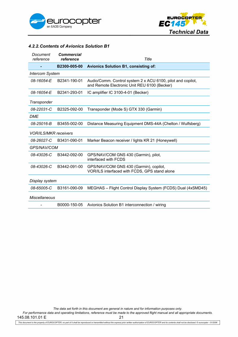
4.2.2. Contents of Avionics Solution B1
Document reference
Commercial reference Title
- B2300-005-00 Avionics Solution B1, consisting of:
Intercom System
08-16054-E B2341-190-01 Audio/Comm. Control system 2 x ACU 6100, pilot and copilot, and Remote Electronic Unit REU 6100 (Becker)
08-16054-E B2341-293-01 IC amplifier IC 3100-4-01 (Becker)
Transponder
08-22031-C B2325-092-00 Transponder (Mode S) GTX 330 (Garmin)
DME
08-25016-B B3455-002-00 Distance Measuring Equipment DMS-44A (Chelton / Wulfsberg)
VOR/ILS/MKR receivers
08-26027-C B3431-090-01 Marker Beacon receiver / lights KR 21 (Honeywell)
GPS/NAV/COM
08-43026-C B3442-092-00 GPS/NAV/COM GNS 430 (Garmin), pilot, interfaced with FCDS
08-43026-C B3442-091-00 GPS/NAV/COM GNS 430 (Garmin), copilot, VOR/ILS interfaced with FCDS, GPS stand alone
Display system
08-65005-C B3161-090-09 MEGHAS – Flight Control Display System (FCDS) Dual (4xSMD45)
Miscellaneous
- B0000-150-05 Avionics Solution B1 interconnection / wiring

Technical Data
The data set forth in this document are general in nature and for information purposes only. For performance data and operating limitations, reference must be made to the approved flight manual and all appropriate documents.
145.08.101.01 E 22 This document is the property of EUROCOPTER; no part of it shall be reproduced or transmitted without the express prior written authorization of EUROCOPTER and its contents shall not be disclosed. © eurocopter - 01/2006
4.2.3. Contents of Avionics Solution B2
Document reference
Commercial reference Title
- B2300-002-00 Avionics Solution B2, consisting of: VHF AM/COM
08-11026-B B2313-092-01 B2313-092-34
VHF AM/COM system VCS-40A (Chelton / Wulfsberg), pilot VHF AM/COM control unit CD-402B (Chelton / Wulfsberg), pilot
08-11026-B B2313-091-01 B2313-091-34
VHF AM/COM system VCS-40A (Chelton / Wulfsberg), copilot VHF AM/COM control unit CD-402B (Chelton / Wulfsberg), copilot
Intercom System
08-16054-E B2341-190-01 Audio/Comm. Control system 2 x ACU 6100, pilot and copilot, and Remote Electronic Unit REU 6100 (Becker)
08-16054-E B2341-293-01 IC amplifier IC 3100-4-01 (Becker)
Transponder
08-22014-B B2325-092-06 B2325-092-36
Transponder (Mode S) MST 67A (Honeywell) Transponder control unit PS 578A (Honeywell)
DME
08-25016-B B3455-002-00 Distance Measuring Equipment DMS-44A (Chelton / Wulfsberg) VOR/ILS/MKR receivers
08-26012-B B3432-092-01
B3432-092-34
VOR/ILS/MKR navigation system VNS-41A (Chelton / Wulfsberg), pilot NAV control unit CD-412B (Chelton / Wulfsberg), pilot
08-26012-B B3432-091-01
B3432-091-34
VOR/ILS/MKR navigation system VNS-41A (Chelton / Wulfsberg), copilot NAV control unit CD-412B (Chelton / Wulfsberg), copilot
Display system
08-65005-C B3161-090-09 MEGHAS – Flight Control Display System (FCDS) Dual (4xSMD45)
Miscellaneous
- B0000-150-02 Avionics Solution B2 interconnection / wiring
ON REQUEST: - NVG compatible version of
Avionics Solutions B1 and B2
- Exchange of 2 x SMD45 on
copilot side to one SMD68

Technical Data
The data set forth in this document are general in nature and for information purposes only. For performance data and operating limitations, reference must be made to the approved flight manual and all appropriate documents.
145.08.101.01 E 23 This document is the property of EUROCOPTER; no part of it shall be reproduced or transmitted without the express prior written authorization of EUROCOPTER and its contents shall not be disclosed. © eurocopter - 01/2006
4.2.4. Minimum required equipment for Avionics Solutions B1 and B2
Minimum required equipment for Avionics Solutions B1 and B2 PINAO
Document reference
Commercial reference Title
Weight (margin ± 3 %)
kg lb 3110
0
3111
0
3111
1
05-37018-B B6701-001-00 Copilot flight controls 6.5 14.3 X X X
05-38011-A B3111-001-03 7“ copilot instrument panel with glare shield 1.6 3.5 X X X
05-39009-B B2514-003-01 Map case in copilot door 0.5 1.1 X X X
05-39011-C B3113-005-20 Illuminated chart holder, pilot side 1.1 2.4 X
05-41005-B B2104-100-00 Bleed air heating system 13.2 29.1 X X X
05-43008-A B2576-003-00 Ventilation for avionics compartment 0.7 1.6 X X X
05-61005-B B2433-002-00 Battery, type Saft, ULM, 40 Ah instead of standard battery
6.2 13.7 X X X
05-68002-B B3343-003-00 Additional electrical unit 1.5 3.3 X X X
06-45026-B B3343-006-00 Landing & search light, 400 / 200 W 4.5 9.9 X X X
06-65005-B B2625-003-00 2nd portable fire extinguisher 2.6 5.7 X
06-67045-C B2563-801-06 ELT C406-N HM (Artex) + NAV option 3.9 8.6 X
B2300-005-00 Avionics Solution B1 82.0 180.7
- Or X X X
B2300-002-00 Avionics Solution B2 95.4 210.3
08-21016-B B3441-090-04 Radar altimeter KRA 405B (Honeywell) 3.2 7.0 X X X
08-43012-B B3442-092-12 GPS NAV system 2101 I/O Approach plus – (FreeFlight) 7
3.8 8.4 X
08-53003-B B2212-300-00 MEGHAS sensor kit 20.7 45.6 X X X
08-72002-B B2212-001-00 Automatic Flight Control System – AFCS 30.5 67.2 X X X
08-81025-B B3132-001-00
M’ARMS® Cockpit Voice and Flight Data Recorder (CVFDR) (ground station not included)
16.0 35.2 X
7 Only possible for Avionics Solution B2
Technical Data
The data set forth in this document are general in nature and for information purposes only. For performance data and operating limitations, reference must be made to the approved flight manual and all appropriate documents.
145.08.101.01 E 24 This document is the property of EUROCOPTER; no part of it shall be reproduced or transmitted without the express prior written authorization of EUROCOPTER and its contents shall not be disclosed. © eurocopter - 01/2006
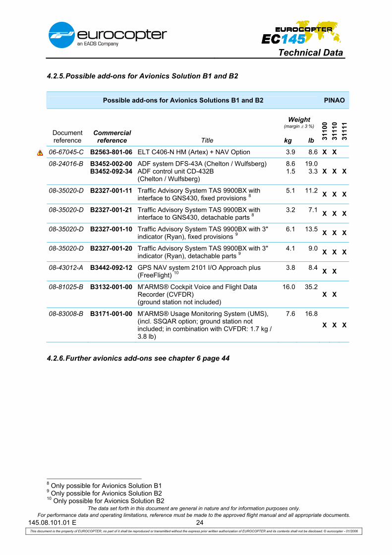
4.2.5. Possible add-ons for Avionics Solution B1 and B2
Possible add-ons for Avionics Solutions B1 and B2 PINAO
Document reference
Commercial reference Title
Weight (margin ± 3 %)
kg lb 31
100
3111
0 31
111
06-67045-C B2563-801-06 ELT C406-N HM (Artex) + NAV Option 3.9 8.6 X X
08-24016-B B3452-002-00 B3452-092-34
ADF system DFS-43A (Chelton / Wulfsberg) ADF control unit CD-432B (Chelton / Wulfsberg)
8.6 1.5
19.0 3.3 X X X
08-35020-D B2327-001-11 Traffic Advisory System TAS 9900BX with interface to GNS430, fixed provisions 8
5.1 11.2 X X X
08-35020-D B2327-001-21 Traffic Advisory System TAS 9900BX with interface to GNS430, detachable parts 8
3.2 7.1 X X X
08-35020-D B2327-001-10 Traffic Advisory System TAS 9900BX with 3" indicator (Ryan), fixed provisions 9
6.1 13.5 X X X
08-35020-D B2327-001-20 Traffic Advisory System TAS 9900BX with 3" indicator (Ryan), detachable parts 9
4.1 9.0 X X X
08-43012-A B3442-092-12 GPS NAV system 2101 I/O Approach plus (FreeFlight) 10
3.8 8.4 X X
08-81025-B B3132-001-00 M’ARMS® Cockpit Voice and Flight Data Recorder (CVFDR) (ground station not included)
16.0 35.2 X X
08-83008-B B3171-001-00 M’ARMS® Usage Monitoring System (UMS), (incl. SSQAR option; ground station not included; in combination with CVFDR: 1.7 kg / 3.8 lb)
7.6 16.8
X X X
4.2.6. Further avionics add-ons see chapter 6 page 44
8 Only possible for Avionics Solution B1 9 Only possible for Avionics Solution B2 10 Only possible for Avionics Solution B2

Technical Data
The data set forth in this document are general in nature and for information purposes only. For performance data and operating limitations, reference must be made to the approved flight manual and all appropriate documents.
145.08.101.01 E 25 This document is the property of EUROCOPTER; no part of it shall be reproduced or transmitted without the express prior written authorization of EUROCOPTER and its contents shall not be disclosed. © eurocopter - 01/2006
BLANK
Technical Data
The data set forth in this document are general in nature and for information purposes only. For performance data and operating limitations, reference must be made to the approved flight manual and all appropriate documents.
145.08.101.01 E 26 This document is the property of EUROCOPTER; no part of it shall be reproduced or transmitted without the express prior written authorization of EUROCOPTER and its contents shall not be disclosed. © eurocopter - 01/2006
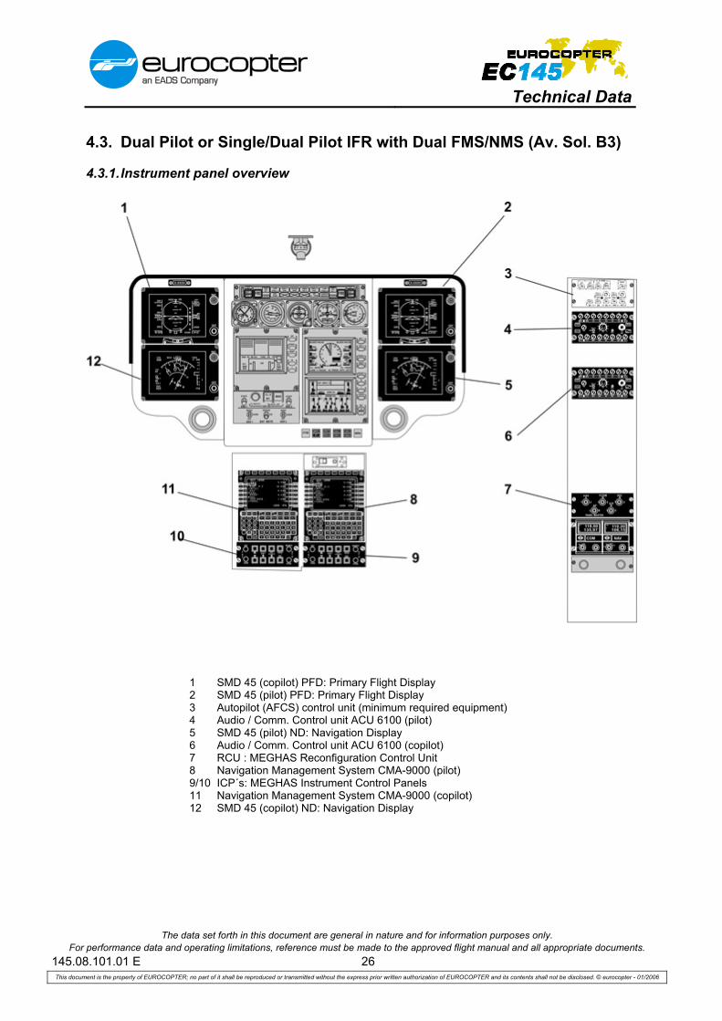
4.3. Dual Pilot or Single/Dual Pilot IFR with Dual FMS/NMS (Av. Sol. B3)
4.3.1. Instrument panel overview
1 SMD 45 (copilot) PFD: Primary Flight Display 2 SMD 45 (pilot) PFD: Primary Flight Display 3 Autopilot (AFCS) control unit (minimum required equipment) 4 Audio / Comm. Control unit ACU 6100 (pilot) 5 SMD 45 (pilot) ND: Navigation Display 6 Audio / Comm. Control unit ACU 6100 (copilot) 7 RCU : MEGHAS Reconfiguration Control Unit 8 Navigation Management System CMA-9000 (pilot) 9/10 ICP´s: MEGHAS Instrument Control Panels 11 Navigation Management System CMA-9000 (copilot) 12 SMD 45 (copilot) ND: Navigation Display
Technical Data
The data set forth in this document are general in nature and for information purposes only. For performance data and operating limitations, reference must be made to the approved flight manual and all appropriate documents.
145.08.101.01 E 27 This document is the property of EUROCOPTER; no part of it shall be reproduced or transmitted without the express prior written authorization of EUROCOPTER and its contents shall not be disclosed. © eurocopter - 01/2006
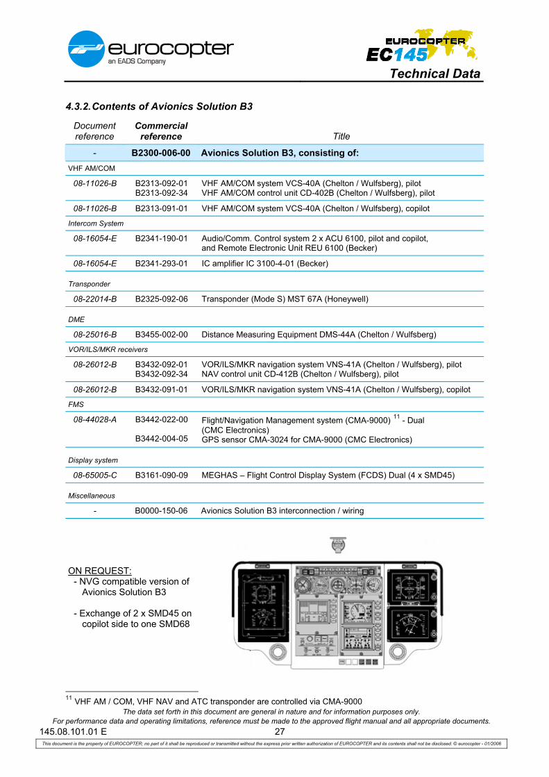
4.3.2. Contents of Avionics Solution B3
Document reference
Commercial reference Title
- B2300-006-00 Avionics Solution B3, consisting of: VHF AM/COM
08-11026-B B2313-092-01 B2313-092-34
VHF AM/COM system VCS-40A (Chelton / Wulfsberg), pilot VHF AM/COM control unit CD-402B (Chelton / Wulfsberg), pilot
08-11026-B B2313-091-01 VHF AM/COM system VCS-40A (Chelton / Wulfsberg), copilot
Intercom System
08-16054-E B2341-190-01 Audio/Comm. Control system 2 x ACU 6100, pilot and copilot, and Remote Electronic Unit REU 6100 (Becker)
08-16054-E B2341-293-01 IC amplifier IC 3100-4-01 (Becker)
Transponder
08-22014-B B2325-092-06 Transponder (Mode S) MST 67A (Honeywell)
DME
08-25016-B B3455-002-00 Distance Measuring Equipment DMS-44A (Chelton / Wulfsberg)
VOR/ILS/MKR receivers
08-26012-B B3432-092-01 B3432-092-34
VOR/ILS/MKR navigation system VNS-41A (Chelton / Wulfsberg), pilot NAV control unit CD-412B (Chelton / Wulfsberg), pilot
08-26012-B B3432-091-01 VOR/ILS/MKR navigation system VNS-41A (Chelton / Wulfsberg), copilot
FMS 08-44028-A B3442-022-00
B3442-004-05
Flight/Navigation Management system (CMA-9000) 11 - Dual (CMC Electronics) GPS sensor CMA-3024 for CMA-9000 (CMC Electronics)
Display system
08-65005-C B3161-090-09 MEGHAS – Flight Control Display System (FCDS) Dual (4 x SMD45)
Miscellaneous
- B0000-150-06 Avionics Solution B3 interconnection / wiring
ON REQUEST: - NVG compatible version of
Avionics Solution B3 - Exchange of 2 x SMD45 on
copilot side to one SMD68
11 VHF AM / COM, VHF NAV and ATC transponder are controlled via CMA-9000

Technical Data
The data set forth in this document are general in nature and for information purposes only. For performance data and operating limitations, reference must be made to the approved flight manual and all appropriate documents.
145.08.101.01 E 28 This document is the property of EUROCOPTER; no part of it shall be reproduced or transmitted without the express prior written authorization of EUROCOPTER and its contents shall not be disclosed. © eurocopter - 01/2006
4.3.3. Minimum required equipment for Avionics Solution B3
Minimum required equipment for Avionics Solutions B3 PINAO
Document reference
Commercial reference Title
Weight (margin ± 3 %)
kg lb 31
100
3111
0 31
111
05-37018-B B6701-001-00 Copilot flight controls 6.5 14.3 X X X
05-38011-A B3111-001-03 7“ copilot instrument panel with glare shield 1.6 3.5 X X X
05-39009-B B2514-003-01 Map case in copilot door 0.5 1.1 X X X
05-39011-C B3113-005-20 Illuminated chart holder, pilot side 1.1 2.4 X
05-41005-B B2104-100-00 Bleed air heating system 13.2 29.1 X X X
05-43008-A B2576-003-00 Ventilation for avionics compartment 0.7 1.6 X X X
05-61005-B B2433-002-00 Battery, type Saft, ULM, 40 Ah instead of standard battery
6.2 13.7 X X X
05-68002-B B3343-003-00 Additional electrical unit 1.5 3.3 X X X
06-45026-B B3343-006-00 Landing & Search light, 400 / 200 W 4.5 9.9 X X X
06-65005-B B2625-003-00 2nd portable fire extinguisher 2.6 5.7 X
06-67045-C B2563-801-06 ELT C406-N HM (Artex) + NAV Option 3.9 8.6 X
B2300-006-00 Avionics Solution B3 110.0 242.5 X X X
08-21016-B B3441-090-04 Radar altimeter KRA 405B (Honeywell) 3.1 6.8 X X X
08-53003-B B2212-300-00 MEGHAS sensor kit 20.7 45.6 X X X
08-72002-B B2212-001-00 Automatic Flight Control System – AFCS 30.5 67.2 X X X
08-81025-B B3132-001-00 M’ARMS® Cockpit Voice and Flight Data Recorder (CVFDR) (ground station not included)
16.0 35.2 X

Technical Data
The data set forth in this document are general in nature and for information purposes only. For performance data and operating limitations, reference must be made to the approved flight manual and all appropriate documents.
145.08.101.01 E 29 This document is the property of EUROCOPTER; no part of it shall be reproduced or transmitted without the express prior written authorization of EUROCOPTER and its contents shall not be disclosed. © eurocopter - 01/2006
4.3.4. Possible add-ons for Avionics Solution B3
Possible add-ons for Avionics Solutions B3 PINAO
Document reference
Commercial reference Title
Weight (margin ± 3 %)
kg lb 31
100
3111
0 31
111
06-67045-C B2563-801-06 ELT C406-N HM (Artex) + NAV option 3.9 8.6 X X
08-24016-B B3452-002-00 ADF system DFS-43A (Chelton / Wulfsberg) controlled via CMA-9000
8.6 19.0 X X X
08-35020-D B2327-001-10 Traffic Advisory System TAS 9900BX with 3" indicator (Ryan), fixed provisions
6.1 13.5 X X X
08-35020-D B2327-001-20 Traffic Advisory System TAS 9900BX with 3" indicator (Ryan), detachable parts
4.1 9.0 X X X
08-81025-B B3132-001-00 M’ARMS® Cockpit Voice and Flight Data Recorder (CVFDR) (ground station not included)
16.0 35.2 X X
08-83008-B B3171-001-00 M’ARMS® Usage Monitoring System (UMS), (incl. SSQAR option; ground station not included; in combination with CVFDR: 1.7 kg / 3.8 lb)
7.6 16.8
X X X
4.3.5. Further avionics add-ons see chapter 6 page 44

Technical Data
The data set forth in this document are general in nature and for information purposes only. For performance data and operating limitations, reference must be made to the approved flight manual and all appropriate documents.
145.08.101.01 E 30 This document is the property of EUROCOPTER; no part of it shall be reproduced or transmitted without the express prior written authorization of EUROCOPTER and its contents shall not be disclosed. © eurocopter - 01/2006
4.4. Single Pilot IFR, based on Avionics Solution C
4.4.1. Instrument panel overview
1 SMD 45 (pilot) PFD: Primary Flight Display 2 Back-up DME indicator SD 442 B 3 Autopilot control unit (minimum required equipment) 4 Audio / Comm. Control unit ACU 6100 (1st system) 5 Audio / Comm. Control unit ACU 6100 (2nd system) 6 RCU: MEGHAS Reconfiguration Control Unit 7 Back-up indicator (CDI) KI 204 8 SMD 45 (pilot) ND: Navigation Display 9 ICP´s: MEGHAS Instrument Control Panels

Technical Data
The data set forth in this document are general in nature and for information purposes only. For performance data and operating limitations, reference must be made to the approved flight manual and all appropriate documents.
145.08.101.01 E 31 This document is the property of EUROCOPTER; no part of it shall be reproduced or transmitted without the express prior written authorization of EUROCOPTER and its contents shall not be disclosed. © eurocopter - 01/2006
4.4.2. Contents of Avionics Solution C
Document reference
Commercial reference Title
- B2300-003-00 Avionics Solution C, consisting of: VHF AM/COM
08-11026-B B2313-092-01 B2313-092-34
VHF AM/COM system VCS-40A (Chelton / Wulfsberg), pilot VHF AM/COM control unit CD-402B (Chelton / Wulfsberg), pilot
08-11026-B B2313-091-01 B2313-091-34
VHF AM/COM system VCS-40A (Chelton / Wulfsberg), copilot VHF AM/COM control unit CD-402B (Chelton / Wulfsberg), copilot
Intercom System
08-16054-E B2341-190-01 Audio/Comm. Control system 2 x ACU 6100, pilot and copilot, and Remote Electronic Unit REU 6100 (Becker)
08-16054-E B2341-293-01 IC amplifier IC 3100-4-01 (Becker)
Transponder
08-22014-B B2325-092-06 B2325-092-36
Transponder (Mode S) MST 67A (Honeywell) Transponder control unit PS 578A (Honeywell)
DME
08-25016-B B3455-002-00 Distance Measuring Equipment DMS-44A (Chelton / Wulfsberg) VOR/ILS/MKR receivers
08-26012-B B3432-092-01
B3432-092-34
VOR/ILS/MKR navigation system VNS-41A (Chelton / Wulfsberg), pilot NAV control unit CD-412B (Chelton / Wulfsberg), pilot
08-26012-B B3432-091-01
B3432-091-34
VOR/ILS/MKR navigation system VNS-41A (Chelton / Wulfsberg), copilot NAV control unit CD-412B (Chelton / Wulfsberg), copilot
08-26012-B B0000-200-12 Back-up CDI KI 204 (Honeywell) and Back-up DME indicator SD 442 B (Chelton / Wulfsberg)
Display system
08-65005-C B3161-092-02 MEGHAS – Flight Control Display System (FCDS) - Single (2 x SMD45)
Miscellaneous
- B0000-150-03 Avionics Solution C interconnection / wiring
ON REQUEST:
- NVG compatible version of Avionics Solution C
- SP IFR with Single sided Garmin GNS430 version

Technical Data
The data set forth in this document are general in nature and for information purposes only. For performance data and operating limitations, reference must be made to the approved flight manual and all appropriate documents.
145.08.101.01 E 32 This document is the property of EUROCOPTER; no part of it shall be reproduced or transmitted without the express prior written authorization of EUROCOPTER and its contents shall not be disclosed. © eurocopter - 01/2006
4.4.3. Minimum required equipment for Avionics Solution C
Minimum required equipment for Avionics Solutions C PINAO
Document reference
Commercial reference Title
Weight (margin ± 3 %)
kg lb 11
100
1111
0 11
111
05-39011-C B3113-005-20 Illuminated chart holder, pilot side 1.1 2.4 X
05-41005-B B2104-100-00 Bleed air heating system 13.2 29.1 X X X
05-43008-A B2576-003-00 Ventilation for avionics compartment 0.7 1.6 X X X
05-61005-B B2433-002-00 Battery, type Saft, ULM, 40 Ah instead of standard battery
6.2 13.7 X X X
05-68002-B B3343-003-00 Additional electrical unit 1.5 3.3 X X X
06-45026-B B3343-006-00 Landing & Search light, 400 / 200 W 4.5 9.9 X X X
06-65005-B B2625-003-00 2nd portable fire extinguisher 2.6 5.7 X
06-67045-C B2563-801-06 ELT C406-N HM (Artex) + NAV Option 3.9 8.6 X
B2300-003-00 Avionics Solution C 92.1 203.0 X X X
08-21016-B B3441-090-04 Radar altimeter KRA 405B (Honeywell) 3.1 6.8 X X X
08-43012-B B3442-092-12 GPS NAV system 2101 I/O Approach plus (FreeFlight)
3.8 8.4 X
08-53003-B B2212-300-00 MEGHAS sensor kit 20.7 45.6 X X X
08-72002-B B2212-001-00 Automatic Flight Control System – AFCS 30.5 67.2 X X X
08-81025-B B3132-001-00 M’ARMS® Cockpit Voice and Flight Data Recorder (CVFDR) (ground station not included)
16.0 35.2 X

Technical Data
The data set forth in this document are general in nature and for information purposes only. For performance data and operating limitations, reference must be made to the approved flight manual and all appropriate documents.
145.08.101.01 E 33 This document is the property of EUROCOPTER; no part of it shall be reproduced or transmitted without the express prior written authorization of EUROCOPTER and its contents shall not be disclosed. © eurocopter - 01/2006
4.4.4. Possible add-ons for Avionics Solution C
Possible add-ons for Avionics Solutions C PINAO
Document reference
Commercial reference Title
Weight (margin ± 3 %)
kg lb 11
100
1111
0 11
111
05-37018-B B6701-001-00 Copilot flight controls 6.5 14.3 X X X
05-38011-A B3111-001-03 7“ copilot instrument panel with glare shield 1.7 3.7 X X X
05-39009-B B2514-003-01 Map case in copilot door 0.5 1.1 X X X
06-67045-C B2563-801-06 ELT C406-N HM (Artex) + NAV Option 3.9 8.6 X X
08-24016-B B3452-002-00 B3452-092-34
ADF system DFS-43A (Chelton / Wulfsberg) ADF control unit CD-432B (Chelton / Wulfsberg)
8.6 1.5
19.0 3.3 X X X
08-35020-D B2327-001-10 Traffic Advisory System TAS 9900BX with 3" indicator (Ryan), fixed provisions
6.1 13.5 X X X
08-35020-D B2327-001-20 Traffic Advisory System TAS 9900BX with 3" indicator (Ryan), detachable parts
4.1 9.0 X X X
08-43012-B B3442-092-12 GPS NAV system 2101 I/O Approach plus (FreeFlight)
3.8 8.4 X X
08-81025-B B3132-001-00 M’ARMS® Cockpit Voice and Flight Data Recorder (CVFDR) (ground station not included)
16.0 35.2 X X
08-83008-B B3171-001-00 M’ARMS® Usage Monitoring System (UMS), (incl. SSQAR option; ground station not included; in combination with CVFDR: 1.7 kg / 3.8 lb)
7.6 16.8
X X X
4.4.5. Further avionics add-ons see chapter 6 page 44
Technical Data
The data set forth in this document are general in nature and for information purposes only. For performance data and operating limitations, reference must be made to the approved flight manual and all appropriate documents.
145.08.101.01 E 34 This document is the property of EUROCOPTER; no part of it shall be reproduced or transmitted without the express prior written authorization of EUROCOPTER and its contents shall not be disclosed. © eurocopter - 01/2006
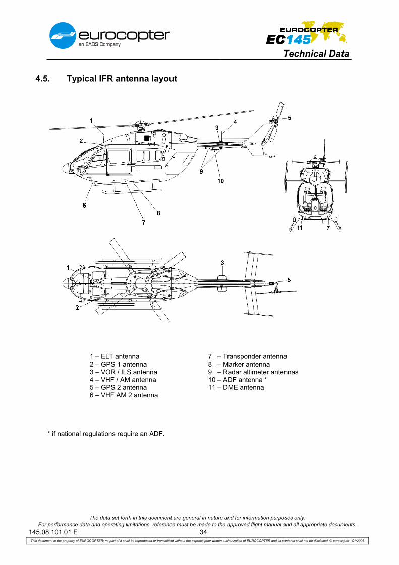
4.5. Typical IFR antenna layout
1 – ELT antenna 7 – Transponder antenna 2 – GPS 1 antenna 8 – Marker antenna 3 – VOR / ILS antenna 9 – Radar altimeter antennas 4 – VHF / AM antenna 10 – ADF antenna * 5 – GPS 2 antenna 11 – DME antenna 6 – VHF AM 2 antenna
* if national regulations require an ADF.

Technical Data
The data set forth in this document are general in nature and for information purposes only. For performance data and operating limitations, reference must be made to the approved flight manual and all appropriate documents.
145.08.101.01 E 35 This document is the property of EUROCOPTER; no part of it shall be reproduced or transmitted without the express prior written authorization of EUROCOPTER and its contents shall not be disclosed. © eurocopter - 01/2006
5. Cabin arrangement
5.1. Passenger transport
5.1.1. Eight (8) corporate passenger cabin configuration
Weight (margin ± 3 %)
Document reference
Commercial reference Title kg lb
06-65005-B B2625-003-00 2nd portable fire extinguisher (cabin floor mounted) 2.6 5.7
07-27003-B B2523-002-00 Passenger seating 8 club seats (standard arrangement) 90.4 199.3
07-81021-A B2512-100-00 Modification of pilot and copilot seat with leather, restraint system in matching color
0.0 0.0
07-81021-A B2523-100-00 Modification of passenger seats (8 club seats) with leather, restraint system in matching color
0.0 0.0
07-83008-A B2525-001-00 Carpet for cockpit, cabin and cargo compartment 14.5 31.9
Technical Data
The data set forth in this document are general in nature and for information purposes only. For performance data and operating limitations, reference must be made to the approved flight manual and all appropriate documents.
145.08.101.01 E 36 This document is the property of EUROCOPTER; no part of it shall be reproduced or transmitted without the express prior written authorization of EUROCOPTER and its contents shall not be disclosed. © eurocopter - 01/2006
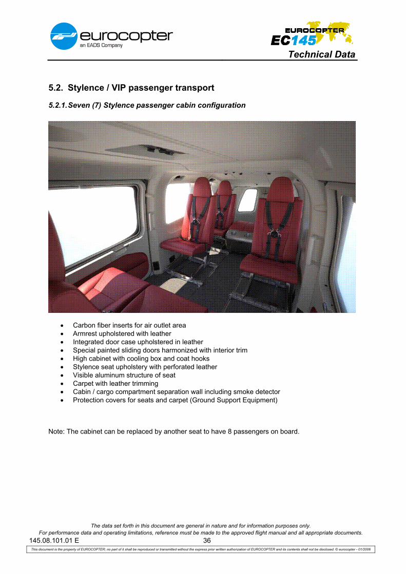
5.2. Stylence / VIP passenger transport
5.2.1. Seven (7) Stylence passenger cabin configuration
• Carbon fiber inserts for air outlet area • Armrest upholstered with leather • Integrated door case upholstered in leather • Special painted sliding doors harmonized with interior trim • High cabinet with cooling box and coat hooks • Stylence seat upholstery with perforated leather • Visible aluminum structure of seat • Carpet with leather trimming • Cabin / cargo compartment separation wall including smoke detector • Protection covers for seats and carpet (Ground Support Equipment)
Note: The cabinet can be replaced by another seat to have 8 passengers on board.

Technical Data
The data set forth in this document are general in nature and for information purposes only. For performance data and operating limitations, reference must be made to the approved flight manual and all appropriate documents.
145.08.101.01 E 37 This document is the property of EUROCOPTER; no part of it shall be reproduced or transmitted without the express prior written authorization of EUROCOPTER and its contents shall not be disclosed. © eurocopter - 01/2006
5.2.2. Four (4) VIP passenger cabin configuration
• Predefined high quality materials • Predefined front and/or rear cabinet • 4 VIP seats covered with leather • Pilot and copilot (if installed) seats covered with leather • Belts and buckles harmonized with the color of the leather • Metallic (various “finish” except gold) air outlets, reading lights and handles • Separation wall between cabin and cargo compartment covered with leather • Interior covered with leather • Hand tufted carpet (long pile)
5.2.3. Variations of the VIP passenger cabin configuration In order to adapt to individual needs, above VIP package can be modified on customer’s request. Possible variations would include cargo compartment cabinets, entertainment system, table with TV or computer displays and swiveling seats.

Technical Data
The data set forth in this document are general in nature and for information purposes only. For performance data and operating limitations, reference must be made to the approved flight manual and all appropriate documents.
145.08.101.01 E 38 This document is the property of EUROCOPTER; no part of it shall be reproduced or transmitted without the express prior written authorization of EUROCOPTER and its contents shall not be disclosed. © eurocopter - 01/2006
5.3. EMS
A wide range of equipment can be offered on request for medevac, primary and secondary EMS missions as well as for multirole missions.

Technical Data
The data set forth in this document are general in nature and for information purposes only. For performance data and operating limitations, reference must be made to the approved flight manual and all appropriate documents.
145.08.101.01 E 39 This document is the property of EUROCOPTER; no part of it shall be reproduced or transmitted without the express prior written authorization of EUROCOPTER and its contents shall not be disclosed. © eurocopter - 01/2006
Available EMS equipment: • Stretchers and loading devices • Incubator transportation systems • Cabinets • Medical crew seats • Special floors • Retainers for medical apparatuses • Attachment points for equipment • Additional stowage options in cabin and cargo compartment • Oxygen systems • Suction systems • Special electrical systems • Special lighting systems • EMS Ground Power Unit connector For efficient and effective operational usage, the EMS equipment needs to be adapted to the specific mission requirements of the customer. Therefore, the definition of the EMS equipment is arranged in a two step approach. Step 1: Definition of basic mission equipment e.g. stretchers, seats, floors, etc. The answers to the following questions will be used to prepare an initial EMS configuration based on customer’s mission, operational area, equipment layout, and flight crew. Mission:
Primary EMS missions e.g. traffic accidents Secondary EMS missions e.g. hospital transfer flights Multirole missions e.g. primary mission: passenger transport / secondary mission: backup as EMS helicopter Other missions e.g. police, civil protection, VIP
Operational area:
City Countryside Mountain Sea
Equipment layout:
Basic Advanced High sophisticated
Flight crew: Number of pilot(s) __ Number of medical crew / passenger(s) __ Number of patient(s) __ Step 2: Definition of special mission equipment e.g. retainers for medical devices, special electrical
systems, oxygen systems, etc. In addition to the basic mission equipment, further special mission equipment is required to assure a full EMS mission. As the requirements of every customer are different, the clarification of the details should be done in a separate dialogue with the EMS specialists of Eurocopter.

Technical Data
The data set forth in this document are general in nature and for information purposes only. For performance data and operating limitations, reference must be made to the approved flight manual and all appropriate documents.
145.08.101.01 E 40 This document is the property of EUROCOPTER; no part of it shall be reproduced or transmitted without the express prior written authorization of EUROCOPTER and its contents shall not be disclosed. © eurocopter - 01/2006
6. Optional equipment
6.1. Further available equipment
General Equipment Weight (margin ± 3 %)
Document reference
Commercial reference Title kg lb
05-02020-B B1111-002-00 Two-color exterior painting instead of single color painting 2.0 4.4
05-02020-B B1111-003-00 Multicolor exterior painting instead of single color painting 2.0 4.4
05-02029-B B1112-001-00 High visibility paint for main rotor blades 0.0 0.0
05-21016-B B8541-001-10 Wire strike protection system, fixed provisions 3.8 8.4
05-21016-B B8541-001-20 Wire strike protection system, detachable parts 7.9 17.4
05-22018-A B7924-001-00 Fuzz burner for engines 1.1 2.4
05-22005-B B7924-002-00 Fuzz burner for tail rotor and intermediate gearbox (in combination with fuzz burner for engines 0.1 kg / 0.2 lbs)
1.1 2.4
05-22015-B B6343-001-00 Fuzz burner for main transmission (in combination with fuzz burner for engines 0.1 kg / 0.2 lbs)
1.1 2.4
05-23007-B B7165-002-00 Engine compressor wash kit 1.7 3.7
05-24018-A B6211-001-00 Main rotor blade erosion kit 1.2 2.7
05-24019-A B6344-001-00 Vector mast moment system 0.2 0.5
05-31029-B B2514-002-00 Tinted sun shades for cockpit windshield roof section 2.1 4.6
05-31030-B B2524-030-10 IFR – training screen, fixed provisions 0.1 0.2
05-31030-B B2524-030-20 IFR – training screen, detachable parts 2.1 4.6
05-31032-B B5213-001-11 Sliding door fastener, intermediate and max. position, LH 0.4 0.9
05-31032-B B5213-001-21 Sliding door fastener, intermediate and max. position, RH 0.4 0.9
05-31034-B B5633-001-10 Window in clam-shell door, LH 0.3 0.7
05-31034-B B5633-001-20 Window in clam-shell door, RH 0.3 0.7
05-31046-A B5632-002-00 Push-out cabin windows 3.2 7.0
05-36008-B B8532-002-30 Multifunction step LH for standard landing gear (instead of standard boarding step)
3.4 7.5
05-36008-B B8532-002-40 Multifunction step RH for standard landing gear (instead of standard boarding step)
3.4 7.5
05-37019-B B6721-001-00 Pedal cover for copilot flight controls 0.3 0.7
05-39010-B B3111-001-10 Map case on instrument panel glare shield 0.6 1.3

Technical Data
The data set forth in this document are general in nature and for information purposes only. For performance data and operating limitations, reference must be made to the approved flight manual and all appropriate documents.
145.08.101.01 E 41 This document is the property of EUROCOPTER; no part of it shall be reproduced or transmitted without the express prior written authorization of EUROCOPTER and its contents shall not be disclosed. © eurocopter - 01/2006
General Equipment (contd.) Weight (margin ± 3 %)
Document reference
Commercial reference Title kg lb
05-39011-C B3113-005-10 Illuminated chart holder, copilot side 1.1 2.4
05-41005-C B2104-100-01 Performance improvement kit for bleed air heating system 3.9 8.6
05-42022-B B2105-001-00 Air conditioning / cooling system – Metro (STC) 51.3 113.1
05-61005-B B2433-003-00 Battery, type “Saft”, ULM, 44 Ah, 24 V instead of standard battery
9.7 21.4
05-62011-B B2420-004-00 AC system 1.5 3.3
05-68001-B B3113-011-00 Additional circuit breaker panel 5.2 11.4
05-68002-B B3343-003-00 Additional electrical unit 1.5 3.3
05-81034-B B2818-100-10 Internal long range fuel tank system, fixed provisions 2.3 5.1
05-81034-B B2818-100-20 Internal long range fuel tank system, detachable parts 38.0 83.8
05-85007-B B7321-001-00 Fuel management system (Fuel flow meters) 1.0 2.2
05-92015-B B6611-001-10 Main rotor blade folding, basic kit 0.3 0.7
05-92015-B B6611-001-20 Main rotor blade folding, fixed provisions for ground handling kit 0.5 1.1
05-92015-B B6611-001-30 Main rotor blade folding, ground handling kit 15.0 33.1
05-93009-B B8544-001-10 Lashing points - 60 kts 1.3 2.8
05-93010-A B8544-002-00 Lashing points - 100 kts 4.5 9.9
Specific Mission Equipment Weight (margin ± 3 %)
Document reference
Commercial reference Title kg lb
06-11023-B B3272-001-20 Snow skids 22.5 49.6
06-11024-B B3274-001-10 Settling protectors, fixed provisions 0.1 0.2
06-11024-B B3274-001-20 Settling protectors, detachable parts 8.1 17.9
06-21019-C B8512-001-10 External hoist, LH, fixed provisions (in combination with emergency floats 12.4 kg / 27.3 lb, if fixed prov. on both LH and RH side, weight has to be checked)
9.8 21.6
06-21019-C B8512-001-11 External hoist, RH, fixed provisions (in combination with emergency floats 13.5 kg / 29.8 lb, if fixed prov. on both LH and RH side, weight has to be checked)
10.9 24.0
06-21019-C B8512-001-20 External hoist (without hook), detachable parts 62.9 138.7
06-21019-C B8512-001-21 External hoist hook and standard damper 3.6 7.9
06-21019-C B8512-001-22 External hoist hook damper floating device 0.4 0.9
06-21019-C B8512-001-23 External hoist hook weight 3.0 6.6

Technical Data
The data set forth in this document are general in nature and for information purposes only. For performance data and operating limitations, reference must be made to the approved flight manual and all appropriate documents.
145.08.101.01 E 42 This document is the property of EUROCOPTER; no part of it shall be reproduced or transmitted without the express prior written authorization of EUROCOPTER and its contents shall not be disclosed. © eurocopter - 01/2006
Specific Mission Equipment (contd.) Weight (margin ± 3 %)
Document reference
Commercial reference Title kg lb
06-21020-B B8512-002-11 External hoist observation light, LH, fixed provisions 0.6 1.3
06-21020-B B8512-002-12 External hoist observation light, RH, fixed provisions 0.6 1.3
06-21020-B B8512-002-20 External hoist observation light, detachable parts 0.8 1.7
06-24011-B B8534-003-11 External rope down device for 2 persons, LH, fixed provisions (in combination with emergency floats 4.9 kg / 10.8 lb)
2.2 4.8
06-24011-B B8534-003-12 External rope down device for 2 persons, RH, fixed provisions (in combination with emergency floats 4.9 kg / 10.8 lb)
2.2 4.8
06-24011-B B8534-003-21 External rope down device for 2 persons, LH, detachable parts – ECMS (STC)
15.2 33.5
06-24011-B B8534-003-22 External rope down device for 2 persons, RH, detachable parts – ECMS (STC)
15.2 33.5
06-26012-B B8511-002-10 Cargo hook mirrors, fixed provisions 0.5 1.1
06-26012-B B8511-002-20 Cargo hook mirrors, detachable parts 3.8 8.4
06-26012-B B8511-002-21 Cover for cargo hook mirrors 0.4 0.9
06-27028-B B8511-005-10 Cargo hook system, fixed provisions 9.3 20.5
06-27028-B B8511-005-20 Cargo hook system, detachable parts 9.0 19.8
06-27029-A B8511-003-10 Cargo hook weighing system, fixed provisions 0.4 0.9
06-27029-A B8511-003-20 Cargo hook weighing system, detachable parts 1.8 4.0
06-27030-B B8511-008-10 Dual cargo hook system, fixed provisions 7.4 16.3
06-27030-B B8511-008-20 Dual cargo hook system, detachable parts 21.4 47.2
06-27031-B B8511-091-10 Dual cargo hook weighing system, fixed provisions 0.3 0.7
06-27031-B B8511-091-20 Dual cargo hook weighing system, detachable parts 2.6 5.7
06-31014-B B8531-001-00 External loudspeaker system with siren 10.2 22.5
06-40001-B B3349-001-00 Tail flood lights for tail rotor and clam-shell doors 1.4 3.1
06-41015-B B3342-001-00 LED Anti-Collision Light (ACL) (instead of standard version) 0.0 0.0
06-42018-B B3343-001-50 Additional landing light at cross tube, LH, 250 W 1.2 2.6
06-45026-B B3343-006-00 Landing & search light 400/200 W, NVG compatible 4.5 9.9
06-45027-B B3346-004-10 Search light SX16, fixed provisions 5.3 11.7
06-45027-B B3346-004-20 Search light SX16, detachable parts (w/o vendor parts) 10.2 22.5
06-45027-B B3346-004-30 Search light SX16, with infrared filter, vendor parts 29.8 65.7
06-46004-B B3344-001-10 Strobe lights 2.0 4.4
06-61017-C B3215-001-10 Emergency floats, fixed provisions (instead of standard skids) 16.7 36.8
06-61017-C B3215-001-20 Emergency floats, detachable parts 50.7 111.8
06-65003-B B2566-001-00 Emergency hammer 0.2 0.4

Technical Data
The data set forth in this document are general in nature and for information purposes only. For performance data and operating limitations, reference must be made to the approved flight manual and all appropriate documents.
145.08.101.01 E 43 This document is the property of EUROCOPTER; no part of it shall be reproduced or transmitted without the express prior written authorization of EUROCOPTER and its contents shall not be disclosed. © eurocopter - 01/2006
Specific Mission Equipment (contd.) Weight (margin ± 3 %)
Document reference
Commercial reference Title kg lb
06-66002-B B3353-015-00 Helicopter Emergency Egress Lighting (HEEL) 5.4 11.9
06-66011-B B3353-006-00 Illuminated signs "NO SMOKING/FASTEN SEAT BELT" 0.2 0.4
06-67048-A B2563-031-00 Underwater Locator Beacon (ULB) 0.3 0.7
06-67049-A B2563-812-00 Automatic Deployable ELT (ADELT) 9.0 19.8
06-69006-B B2341-006-61 Voice alert generator (611-014) 0.5 1.1
06-71007-B B2524-003-10 Separation curtain for cockpit / cabin, fixed provisions 0.1 0.2
06-71007-B B2524-003-20 Separation curtain for cockpit / cabin, detachable parts 1.1 2.4
06-81010-B B8503-001-10 Fire extinguishing bucket attachment (Bambi Bucket), fixed provisions
0.8 1.8
Interior Layout Weight (margin ± 3 %)
Document reference
Commercial reference Title kg lb
07-00017-B B2581-002-20 Comfort improvement kit 24.1 53.1
07-15014-B B2512-003-10 Height adjustable pilot seat (instead of standard pilot seat) 1.8 4.0
07-15014-B B2512-003-20 Height adjustable copilot seat (instead of standard copilot seat) 1.8 4.0
07-27003-B B2523-002-00 Passenger seating, 8 club seats (standard arrangement) - other seating arrangements on request
90.4 199.3
07-27009-B B2522-009-20 High-density seating, 9 seats - Simula (STC) 114.5 252.4
07-30019-B B2581-001-00 Basic sound proofing kit 6.0 13.2
07-40010-B B2513-220-00 Washable floor covering for cockpit, cabin and cargo compartment
14.1 31.1
07-50032-B B5212-001-30 Jettisonable sliding doors 0.0 0.0
07-50033-B B5212-001-00 Jettisonable cockpit doors 0.6 1.3
07-50037-B B5205-008-00 Spoiler position for cockpit doors 1.0 2.2
07-50055-A B5211-010-00 Door catch system for cockpit doors 0.2 0.4
07-50055-A B5211-011-00 Door catch system for sliding doors 0.2 0.4
07-60019-A B2552-001-00 Variable tie-down net 3.3 7.3
07-75020-B B2514-300-00 Attachment rails in cabin ceiling 3.4 7.5
07-74044-A AEL-40120-004-1
Carbon Stretcher dual use, fixed provisions – Aerolite (STC) 1.0 2.2
07-74044-A AEL-40120-004-2
Carbon Stretcher dual use, detachable parts – Aerolite (STC) 11.0 24.3
07-90016-B B2524-008-11 Multi-purpose fittings in cabin, LH 3.1 6.8
07-90016-B B2524-008-12 Multi-purpose fittings in cabin, RH 3.1 6.8

Technical Data
The data set forth in this document are general in nature and for information purposes only. For performance data and operating limitations, reference must be made to the approved flight manual and all appropriate documents.
145.08.101.01 E 44 This document is the property of EUROCOPTER; no part of it shall be reproduced or transmitted without the express prior written authorization of EUROCOPTER and its contents shall not be disclosed. © eurocopter - 01/2006
6.2. Avionics
Weight (margin ± 3 %)
Document reference
Commercial reference Title kg lb
08-15031-B B2319-001-10 Fixed provisions for GSM phone (antenna, 28VDC, interfacing to ICS)
0,8 1,8
08-15511-B B2315-092-00 IRIDIUM satellite phone AEROPHONE (Aerodata) 4.0 8.8
08-16054-E B2341-193-01 Audio/Comm. control system ACU 6100 (Becker), PAX/3rd station, cabin RH (standard version)
2.0 4.4
08-16054-E B2341-845-00 Audio/Comm. control system ACU 6100 (Becker), EMS version (delivered as loose item, incl. connector interface in LH passenger cabin ceiling)
1.4 3.1
08-17041-A B2331-001-10 Cabin loudspeaker, fixed provisions 1.6 3.5
08-17041-A B2331-001-20 Cabin loudspeaker, detachable parts 0.6 1.3
08-18023-B B2315-001-10 Headset H 10-76 (David Clark), low impedance, spiral wire 0.6 1.3
08-18023-B B2315-001-14 Headset H 10-76 ANR/ENC (David Clark), low impedance, spiral wire
0.8 1.8
08-31037-B B3443-004-00 B2571-001-00
Search And Rescue weather radar RDR 1600 (Telephonics) + Radar radome for RDR 1600
16.1 4.7
35.510.4
08-31044-A B3443-005-10 B3443-005-21 B2571-002-00
Color weather radar RDR 2000, installation provisions (electrical and mechanical) + Color weather radar RDR 2000, vendor parts (Honeywell) incl.
control panel CP 466 + Color weather radar RDR 2000, radar radome
2.5
6.0
2.0
5.5
13.2
4.4
08-46021-C B3168-092-04 Moving map EURONAV IV - RN6 (Euro Avionics) interfaced with FCDS, basic version 12 (enhanced options and maps on request)
6.6 14.6
08-53005-B B3424-000-00 AHRS Free Steering Mode 0.6 1.3
08-65006-B B3443-010-00 Video Radar Unit (VRU) 4.8 10.6
12 Tactical mission equipment cannot be certified by German Civil Aviation Authorities. Eurocopter will
ensure that the equipment is compatible with the basic helicopter and will assist the customer in obtaining certification or acceptance approval in his country.

Technical Data
The data set forth in this document are general in nature and for information purposes only. For performance data and operating limitations, reference must be made to the approved flight manual and all appropriate documents.
145.08.101.01 E 45 This document is the property of EUROCOPTER; no part of it shall be reproduced or transmitted without the express prior written authorization of EUROCOPTER and its contents shall not be disclosed. © eurocopter - 01/2006
Tactical radios
Fixed provisions can be offered on request.
NVG Equipment
Different solutions can be offered on request: All avionics solutions can be NVG modified. NVG compatible:
• standard cockpit layout (excluding avionics solution) • cabin and cargo compartment lighting • illuminated chart holder, pilot and/or copilot side • cabin loudspeaker • landing & search light 400/200 W
NVG friendly external lighting kit IR flasher
Broadcast, Thermal Imaging and Video Surveillance Equipment
Different FLIR systems and operator consoles on request.

Technical Data
The data set forth in this document are general in nature and for information purposes only. For performance data and operating limitations, reference must be made to the approved flight manual and all appropriate documents.
145.08.101.01 E 46 This document is the property of EUROCOPTER; no part of it shall be reproduced or transmitted without the express prior written authorization of EUROCOPTER and its contents shall not be disclosed. © eurocopter - 01/2006
6.3. Offshore
Various equipment can be offered on request:
• Automatic Deployable ELT • Emergency floats • Life raft installation • Jettisonable cockpit doors • AHRS free steering mode • Helicopter Emergency Egress Lighting (HEEL) • Underwater Locator Beacon • Search and weather radar • Traffic Advisory System TAS 9900BX • Cabin loudspeaker / Passenger address system • Corrosion protection treatment for offshore operation • Push-out cabin windows • Enhanced Ground Proximity Warning System
(EGPWS)

Technical Data
The data set forth in this document are general in nature and for information purposes only. For performance data and operating limitations, reference must be made to the approved flight manual and all appropriate documents.
145.08.101.01 E 47 This document is the property of EUROCOPTER; no part of it shall be reproduced or transmitted without the express prior written authorization of EUROCOPTER and its contents shall not be disclosed. © eurocopter - 01/2006
7. Table of constraints
Each item or list of items shown beside the symbol is concerned by this chapter; please read it carefully in order to find all constraints.
7.1. General Checklist for Incompatibilities
Detachable parts require the related fixed provisions.
Only one option (out of several possibilities listed in chapter 6) can be selected for each following
specific category: - External painting - Battery - Cargo hook system - Intercom 3rd Station in cabin - Lashing points
All recommended configurations in Chapter 5 (cabin arrangement) exclude each other. Mixed configurations are possible, but have to be individually checked.
Commercial reference Title Constraint Commercial
reference Title
B8511-002-20 Cargo hook mirrors, detachable parts
B2571-001-00 and
B2571-002-00
Radar radome for RDR1600 and RDR2000
B3346-004-20 Search light SX16, detachable parts
8541-001-20 Wire Strike Protection System (WSPS), detachable parts
The protective capability is significantly degraded in combination
with:
FLIR camera system, detachable parts

Technical Data
The data set forth in this document are general in nature and for information purposes only. For performance data and operating limitations, reference must be made to the approved flight manual and all appropriate documents.
145.08.101.01 E 48 This document is the property of EUROCOPTER; no part of it shall be reproduced or transmitted without the express prior written authorization of EUROCOPTER and its contents shall not be disclosed. © eurocopter - 01/2006
7.2. Legend and constraints chart
XCL Impossibility of simultaneous fitment of the fixed parts of 2 items of equipment
REQ Requires the fitting of mentioned item
NSF Total or partial incompatibility of simultaneous fitment of the removable parts of two items of equipment
Commercial Reference Installation
Nature of the
ConstraintCommercial Reference Installation
B2105-001-00 Air conditioning/cooling system – Metro (STC)
XCL B2563-812-00 Automatic Deployable ELT (ADELT)
B2212-001-00 Automatic Flight Control System - AFCS
REQ B3441-090-04 Radar altimeter KRA 405B (Honeywell)
B2341-193-01 Audio/Comm. control system (PAX/3rd station) ACU 6100 (Becker) Standard version
XCL - Recommended EMS configurations
B2341-845-00 Audio/Comm. control system (PAX/3rd station) ACU 6100 (Becker) EMS version
REQ - Recommended Aerolite EMS configurations with overhead compartment
B2523-002-00 Passenger seating, 8 club seats XCL B2522-009-20 High-density seating, 9 pax configuration - Simula (STC)
B2523-002-00 Passenger seating, 8 club seats REQ B2625-003-00 2nd portable fire extinguisher B2522-009-20 High-density seating, 9 pax
configuration - Simula (STC) REQ B2524-008-11 Multi-purpose fittings in cabin, LH
B2522-009-20 High-density seating, 9 pax configuration - Simula (STC)
REQ B2524-008-12 Multi-purpose fittings in cabin, RH
B2522-009-20 High-density seating, 9 pax configuration - Simula (STC)
XCL B2523-002-00 Passenger seating, 8 club seats
B2563-801-06 ELT C406-N HM (Artex) + NAV opt REQ A GPS system B2818-100-20 Internal long range fuel tank system,
detachable parts NSF B2523-002-00 Passenger seating, 8 club seats, three
rear seats B3132-001-00 M’ARMS® CVFDR REQ B2212-001-00 Automatic Flight Control System –
AFCS B3132-001-00 M’ARMS® CVFDR XCL B2563-031-00 Underwater Locator Beacon (ULB) B3168-092-04 Digital moving Map EURONAV IV –
RN6 (Euro Avionics) REQ B3443-010-00 VRU
A GPS system B3171-001-00 M’ARMS® Usage Monitoring
System REQ B2212-001-00 Automatic Flight Control System –
AFCS B3272-001-20 Snow skids NSF B3274-001-20 Settling protectors, detachable parts B3274-001-20 Settling protectors, detachable parts NSF B3272-001-20 Snow skids B2300-003-00 Avionics solution C (without copilot
instrument panel glare shield) XCL B3313-004-10 Illuminated chart holder for copilot
B3343-001-50 Additional landing light, cross tube mounted LH, 250 W
REQ B3113-011-00 Additional circuit breaker panel
B3443-004-00 Search And Rescue weather radar RDR1600 (Telephonics)
REQ B2571-001-00 B2420-004-00B3443-010-00
Radar radome for RDR 1600 AC system VRU
B3443-005-10 B3443-005-21
Color weather radar RDR 2000 (Honeywell)
REQ B2571-002-00 B3443-010-00
Radar radome VRU
B3343-006-00 Landing & search light 400/200 W REQ B3343-003-00 Additional electrical unit
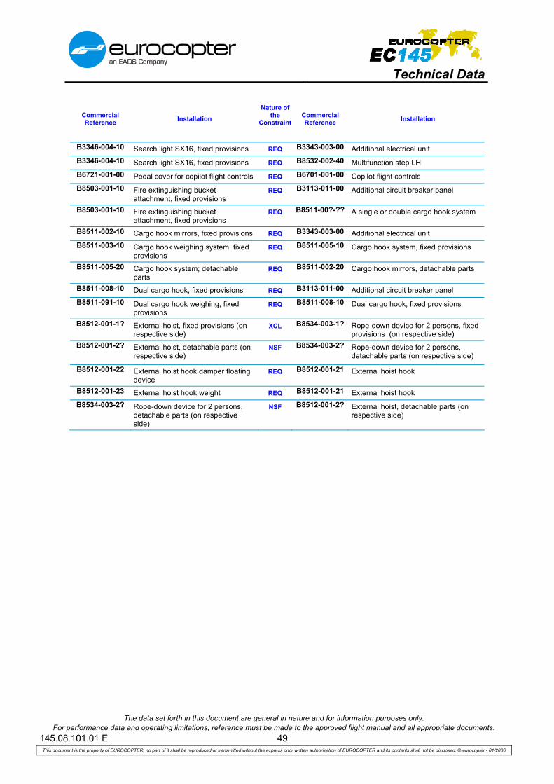
Technical Data
The data set forth in this document are general in nature and for information purposes only. For performance data and operating limitations, reference must be made to the approved flight manual and all appropriate documents.
145.08.101.01 E 49 This document is the property of EUROCOPTER; no part of it shall be reproduced or transmitted without the express prior written authorization of EUROCOPTER and its contents shall not be disclosed. © eurocopter - 01/2006
Commercial Reference Installation
Nature of the
ConstraintCommercial Reference Installation
B3346-004-10 Search light SX16, fixed provisions REQ B3343-003-00 Additional electrical unit B3346-004-10 Search light SX16, fixed provisions REQ B8532-002-40 Multifunction step LH B6721-001-00 Pedal cover for copilot flight controls REQ B6701-001-00 Copilot flight controls B8503-001-10 Fire extinguishing bucket
attachment, fixed provisions REQ B3113-011-00 Additional circuit breaker panel
B8503-001-10 Fire extinguishing bucket attachment, fixed provisions
REQ B8511-00?-?? A single or double cargo hook system
B8511-002-10 Cargo hook mirrors, fixed provisions REQ B3343-003-00 Additional electrical unit B8511-003-10 Cargo hook weighing system, fixed
provisions REQ B8511-005-10 Cargo hook system, fixed provisions
B8511-005-20 Cargo hook system; detachable parts
REQ B8511-002-20 Cargo hook mirrors, detachable parts
B8511-008-10 Dual cargo hook, fixed provisions REQ B3113-011-00 Additional circuit breaker panel B8511-091-10 Dual cargo hook weighing, fixed
provisions REQ B8511-008-10 Dual cargo hook, fixed provisions
B8512-001-1? External hoist, fixed provisions (on respective side)
XCL B8534-003-1? Rope-down device for 2 persons, fixed provisions (on respective side)
B8512-001-2? External hoist, detachable parts (on respective side)
NSF B8534-003-2? Rope-down device for 2 persons, detachable parts (on respective side)
B8512-001-22 External hoist hook damper floating device
REQ B8512-001-21 External hoist hook
B8512-001-23 External hoist hook weight REQ B8512-001-21 External hoist hook B8534-003-2? Rope-down device for 2 persons,
detachable parts (on respective side)
NSF B8512-001-2? External hoist, detachable parts (on respective side)

Technical Data
The data set forth in this document are general in nature and for information purposes only. For performance data and operating limitations, reference must be made to the approved flight manual and all appropriate documents.
145.08.101.01 E 50 This document is the property of EUROCOPTER; no part of it shall be reproduced or transmitted without the express prior written authorization of EUROCOPTER and its contents shall not be disclosed. © eurocopter - 01/2006
8. Main performance
The following performance values and figures refer to an EC145, equipped with average production engines.
Unless otherwise specified, the values and figures refer to a clean helicopter at Sea Level (SL), in International Standard Atmosphere (ISA) and zero wind condition.
Performance on 2 engines (AEO)
Gross Weight kglb
2,4005,290
2,7005,950
3,0006,615
3,3007,275
3,5857,905
Maximum speed (VNE) km/hkts
278150
278150
268145
268145
268145
Maximum cruising speed (VH) km/hkts
256138
254137
252136
250135
246133
Fuel consumption at maximum cruising speed kg/hlb/h
258569
258569
258569
258569
258569
Recommended cruising speed km/hkts
237128
239129
241130
243131
243131
Fuel consumption at recommended cruising speed
kg/hlb/h
234516
238525
244538
251554
254560
Fuel consumption at 65 KIAS kg/hlb/h
178392
183404
190418
197434
204450
Maximum rate of climb, TOP m/sft/min
14.92940
13.02560
11.22210
9.31840
8.11600
Hover ceiling IGE (3 ft AGL), TOP mft
5,48518,000
5,48518,000
4,69515,400
3,84012,600
2,9259,600
Hover ceiling OGE, TOP, ISA mft
5,48518,000
5,12016,800
4,34514,260
3,44511,300
7702,530
Service ceiling, MCP, (climb reserve 200 ft/min), ISA
mft
5,48518,000
5,48518,000
5,48518,000
5,48518,000
5,24017,200
Range (SL, ISA) with max. fuel capacity at recommended cruise speed (no reserve)
Std fuel tank configuration (694 kg)
Long range fuel tank inst. (869 kg)
kmnmkmnm
------------
705380
------
700377875472
685370865467
680370855461
Endurance (SL, ISA) with maximum fuel capacity at 65 KIAS (no reserve)
Std fuel tank configuration (694 kg) Long range fuel tank inst. (869 kg)
h:minh:min
------
3:55---
3:504:50
3:404:40
3:354:30

Technical Data
The data set forth in this document are general in nature and for information purposes only. For performance data and operating limitations, reference must be made to the approved flight manual and all appropriate documents.
145.08.101.01 E 51 This document is the property of EUROCOPTER; no part of it shall be reproduced or transmitted without the express prior written authorization of EUROCOPTER and its contents shall not be disclosed. © eurocopter - 01/2006
Performance on 1 engine (OEI)
Gross Weight kglb
2,4005,290
2,7005,950
3,0006,615
3,3007,275
3,5857,905
Single engine service ceiling, OEI, MCP, 100 ft/min climb reserve, ISA
mft
5,45617,900
4,59015,060
3,75512,320
2,9669,730
1,9966,550
Single engine service ceiling, OEI, MCP, 100 ft/min climb reserve, ISA + 20°C
mft
4,96816,300
4,02913,220
3,09710,160
2,1857,170
1,3384,390
Maximum rate of climb, OEI, MCP, SL, ISA m/sft/min
5.71,120
4.4860
3.2630
2.1420
1.2230
Max. temperature for CAT A, take-off from clear heliport at SL °C + 50 + 50 + 50 + 49 + 42
Max. weight, HOGE, SL, ISA, (OEI 2.5 min-power)
kglb
2,785 6,140
Max. weight, HOGE, SL, ISA + 20°C, (OEI 2.5 min-power)
kglb
2,520 5,555
Max. weight, CAT A, VTOL, SL, ISA kglb
3,415 7,530
Max. weight, CAT A, VTOL, SL, ISA + 10°C kglb
3,320 7,320
Operating Limitations The helicopter can be operated within the following altitude and temperature limitations (according to the Flight Manual):
Maximum operating altitude 5,485 m PA18,000 ft PA
Maximum operating altitude for hover in ground effect, takeoff and landing
5,485 m PA or DA18,000 ft PA or DA
whichever is less
Minimum temperature - 45 °C
Maximum temperature ISA + 35 °C(max. + 50 °C)
Abbreviations AGL Above Ground Level OGE Out Of Ground Effect
DA Density Altitude PA Pressure Altitude
IGE In Ground Effect SL Sea Level
ISA International Standard Atmosphere TOP Take-Off Power
MCP Maximum Continuous Power VNE Never-Exceed Speed
OEI One Engine Inoperative VTOL Vertical Take-Off and Landing

Technical Data
The data set forth in this document are general in nature and for information purposes only. For performance data and operating limitations, reference must be made to the approved flight manual and all appropriate documents.
145.08.101.01 E 52 This document is the property of EUROCOPTER; no part of it shall be reproduced or transmitted without the express prior written authorization of EUROCOPTER and its contents shall not be disclosed. © eurocopter - 01/2006
Hover In Ground Effect (HIGE, TOP)
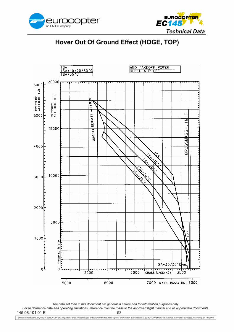
Technical Data
The data set forth in this document are general in nature and for information purposes only. For performance data and operating limitations, reference must be made to the approved flight manual and all appropriate documents.
145.08.101.01 E 53 This document is the property of EUROCOPTER; no part of it shall be reproduced or transmitted without the express prior written authorization of EUROCOPTER and its contents shall not be disclosed. © eurocopter - 01/2006
Hover Out Of Ground Effect (HOGE, TOP)

Technical Data
The data set forth in this document are general in nature and for information purposes only. For performance data and operating limitations, reference must be made to the approved flight manual and all appropriate documents.
145.08.101.01 E 54 This document is the property of EUROCOPTER; no part of it shall be reproduced or transmitted without the express prior written authorization of EUROCOPTER and its contents shall not be disclosed. © eurocopter - 01/2006
Take-Off Weight, Cat. A, Clear Heliport

Technical Data
The data set forth in this document are general in nature and for information purposes only. For performance data and operating limitations, reference must be made to the approved flight manual and all appropriate documents.
145.08.101.01 E 55 This document is the property of EUROCOPTER; no part of it shall be reproduced or transmitted without the express prior written authorization of EUROCOPTER and its contents shall not be disclosed. © eurocopter - 01/2006
Take-Off Weight, Cat. A, VTOL

Technical Data
The data set forth in this document are general in nature and for information purposes only. For performance data and operating limitations, reference must be made to the approved flight manual and all appropriate documents.
145.08.101.01 E 56 This document is the property of EUROCOPTER; no part of it shall be reproduced or transmitted without the express prior written authorization of EUROCOPTER and its contents shall not be disclosed. © eurocopter - 01/2006
Maximum Cruising Speed

Technical Data
The data set forth in this document are general in nature and for information purposes only. For performance data and operating limitations, reference must be made to the approved flight manual and all appropriate documents.
145.08.101.01 E 57 This document is the property of EUROCOPTER; no part of it shall be reproduced or transmitted without the express prior written authorization of EUROCOPTER and its contents shall not be disclosed. © eurocopter - 01/2006
Maximum Rate Of Climb, TOP, 3585 kg (MTOW)

Technical Data
The data set forth in this document are general in nature and for information purposes only. For performance data and operating limitations, reference must be made to the approved flight manual and all appropriate documents.
145.08.101.01 E 58 This document is the property of EUROCOPTER; no part of it shall be reproduced or transmitted without the express prior written authorization of EUROCOPTER and its contents shall not be disclosed. © eurocopter - 01/2006
Maximum Rate of Climb, MCP, 3585 kg (MTOW)

Technical Data
The data set forth in this document are general in nature and for information purposes only. For performance data and operating limitations, reference must be made to the approved flight manual and all appropriate documents.
145.08.101.01 E 59 This document is the property of EUROCOPTER; no part of it shall be reproduced or transmitted without the express prior written authorization of EUROCOPTER and its contents shall not be disclosed. © eurocopter - 01/2006
Fuel consumption (AEO)
see page 61

Technical Data
The data set forth in this document are general in nature and for information purposes only. For performance data and operating limitations, reference must be made to the approved flight manual and all appropriate documents.
145.08.101.01 E 60 This document is the property of EUROCOPTER; no part of it shall be reproduced or transmitted without the express prior written authorization of EUROCOPTER and its contents shall not be disclosed. © eurocopter - 01/2006
Fuel consumption (AEO)
see page 61

Technical Data
The data set forth in this document are general in nature and for information purposes only. For performance data and operating limitations, reference must be made to the approved flight manual and all appropriate documents.
145.08.101.01 E 61 This document is the property of EUROCOPTER; no part of it shall be reproduced or transmitted without the express prior written authorization of EUROCOPTER and its contents shall not be disclosed. © eurocopter - 01/2006
Fuel consumption (AEO)
see pages 59 and 60
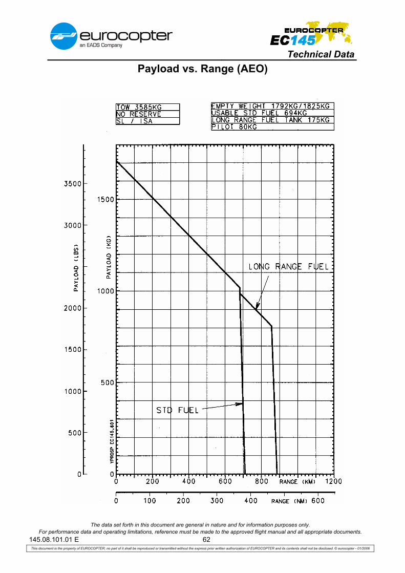
Technical Data
The data set forth in this document are general in nature and for information purposes only. For performance data and operating limitations, reference must be made to the approved flight manual and all appropriate documents.
145.08.101.01 E 62 This document is the property of EUROCOPTER; no part of it shall be reproduced or transmitted without the express prior written authorization of EUROCOPTER and its contents shall not be disclosed. © eurocopter - 01/2006
Payload vs. Range (AEO)

Technical Data
The data set forth in this document are general in nature and for information purposes only. For performance data and operating limitations, reference must be made to the approved flight manual and all appropriate documents.
145.08.101.01 E 63 This document is the property of EUROCOPTER; no part of it shall be reproduced or transmitted without the express prior written authorization of EUROCOPTER and its contents shall not be disclosed. © eurocopter - 01/2006
BLANK

Technical Data
The data set forth in this document are general in nature and for information purposes only. For performance data and operating limitations, reference must be made to the approved flight manual and all appropriate documents.
145.08.101.01 E 64 This document is the property of EUROCOPTER; no part of it shall be reproduced or transmitted without the express prior written authorization of EUROCOPTER and its contents shall not be disclosed. © eurocopter - 01/2006
9. Support information
9.1. Assets
Proven reliability and availability based on experience Eurocopter’s helicopter production programs have developed a strong reputation world-wide for being fully committed to providing customers with operational, capable aircraft that achieve high availability combined with cost-effective support systems. To achieve this record of performance, Eurocopter has stressed the importance of working together with its customers to ensure constant feedback on their demonstrated in-service Reliability, Availability and Maintainability/Testability (RAM) data. The main objective is to reach the most optimized operational cost ensuring the highest flight safety. Eurocopter has built and delivered EC145 helicopters for almost ten years. More than 155 helicopters are in service world wide. The total flight hours accumulated at the end of the year 2007 are approximately 158.000 Fh. The “lead the fleet” aircraft has accumulated approximately 3.500 Fh.
9.2. Inspection Program
The Maintenance Program specifies the intervals between maintenance operations that are recommended by Eurocopter, irrespective of whether they are mandatory or not. The program can:
– either be used as is, – or be adapted by each operator to suit his own specific organization, provided he complies
with the maximum intervals. The following table provides an overview of all inspections. Scheduled inspections with shorter time intervals have to be added to those with longer time intervals. This means, that for example the Periodical Inspection contains the Supplementary Check and the 12-Month Inspection. •
Scheduled Airframe Inspection Maintenance Level Estimated Man Hours
Pre-flight Check O - Level Pilot task
Supplementary check at 100 hours O - Level 1,3 hours
12-month inspection I - Level 16 hours
Periodic inspection at 600 hours I - Level 82 hours
Extended periodic inspection at 6000 hours I - Level 187 hours
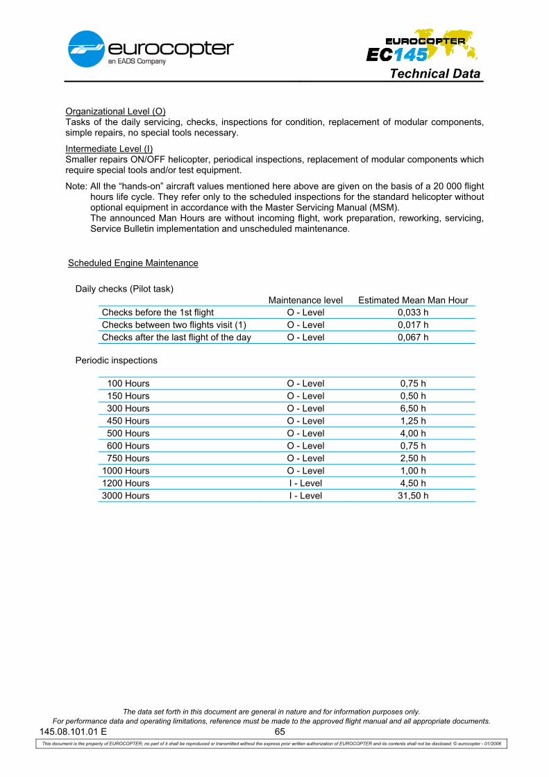
Technical Data
The data set forth in this document are general in nature and for information purposes only. For performance data and operating limitations, reference must be made to the approved flight manual and all appropriate documents.
145.08.101.01 E 65 This document is the property of EUROCOPTER; no part of it shall be reproduced or transmitted without the express prior written authorization of EUROCOPTER and its contents shall not be disclosed. © eurocopter - 01/2006
Organizational Level (O) Tasks of the daily servicing, checks, inspections for condition, replacement of modular components, simple repairs, no special tools necessary.
Intermediate Level (I) Smaller repairs ON/OFF helicopter, periodical inspections, replacement of modular components which require special tools and/or test equipment.
Note: All the “hands-on” aircraft values mentioned here above are given on the basis of a 20 000 flight hours life cycle. They refer only to the scheduled inspections for the standard helicopter without optional equipment in accordance with the Master Servicing Manual (MSM). The announced Man Hours are without incoming flight, work preparation, reworking, servicing, Service Bulletin implementation and unscheduled maintenance.
Scheduled Engine Maintenance Daily checks (Pilot task) Maintenance level Estimated Mean Man Hour Checks before the 1st flight O - Level 0,033 h Checks between two flights visit (1) O - Level 0,017 h Checks after the last flight of the day O - Level 0,067 h Periodic inspections 100 Hours O - Level 0,75 h 150 Hours O - Level 0,50 h 300 Hours O - Level 6,50 h 450 Hours O - Level 1,25 h 500 Hours O - Level 4,00 h 600 Hours O - Level 0,75 h 750 Hours O - Level 2,50 h 1000 Hours O - Level 1,00 h 1200 Hours I - Level 4,50 h 3000 Hours I - Level 31,50 h

Technical Data
The data set forth in this document are general in nature and for information purposes only. For performance data and operating limitations, reference must be made to the approved flight manual and all appropriate documents.
145.08.101.01 E 66 This document is the property of EUROCOPTER; no part of it shall be reproduced or transmitted without the express prior written authorization of EUROCOPTER and its contents shall not be disclosed. © eurocopter - 01/2006
9.3. Main components Time Between Overhaul (TBO) / Service Life Limit (SLL)
Main Components TBO
as per MSM Rev. 7
SLL as per
MSM Rev. 7
Cartridge of Fuel Pump 5.000 Fh Main Rotor Blade Assy 12.000 Fh Main Transmission 3.600 Fh Main Rotor Shaft 30.000 Fh Freewheel Clutch 3.600 Fh Intermediate Gearbox 2.100 Fh Input Shaft (Intermediate Gearbox) 2.100 Fh Output Shaft (Intermediate Gearbox) 2.100 Fh Laminated Pile Assy (Tail Rotor Head) 13.000 Flights Tail Rotor Transmission 2.100 Fh Input Shaft (Tail Rotor Transmission) 2.100 Fh Output Shaft (Tail Rotor Transmission) 2.100 Fh Short Front Shaft (Tail Rotor Drive) 20.000 Fh Long Shaft (Tail Rotor Drive) 2.600 Fh Short Rear Shaft (Tail Rotor Drive) 30.000 Fh Engine 3.000 Fh
Note: list non-exhaustive Time Between Overhauls (TBO) : The component in question must be removed at each interval that corresponds to the value indicated, in order to undergo the operations in a specialized workshop that will enable it to be put back into service for the next interval. A TBO is granted with a 10 % operational margin, limited at +300 hours. The given time limit may be exceeded by 3% of the respective interval. All subcomponents may have a Service Life limit, rated above the TBO limit. Service Life Limited (SLL) : The service life limit is an airworthiness limit. The component in question must be removed from service when it reaches the limit indicated.

Technical Data
The data set forth in this document are general in nature and for information purposes only. For performance data and operating limitations, reference must be made to the approved flight manual and all appropriate documents.
145.08.101.01 E 67 This document is the property of EUROCOPTER; no part of it shall be reproduced or transmitted without the express prior written authorization of EUROCOPTER and its contents shall not be disclosed. © eurocopter - 01/2006
9.4. Eurocopter Maintenance Support Programs
EUROCOPTER offers its clients a comprehensive array of repair and overhaul services to ensure availability and costs control. This array of services ranges from basic OEM repair and overhaul services up to comprehensive Parts By the Hour (PBH) maintenance programs. The different services are each tailored for one different user profiles and demands, such as customers:
• with a high number of flight hours, • with a low number of flight hours, • looking for immediate component availability, • that wish budget control, • …
To respond to the different customers’ demands EUROCOPTER offers the following flexible and modular services:
• Classical Support • Standard exchange • Repair with guaranteed Turn Around Times (TAT) • Guaranteed Direct Maintenance Costs (DMC) • Unscheduled Maintenance Insurance Plan • Parts By the Hour service
9.4.1. Classical Support The classical support consists of a comprehensive Initial Provisioning package to sustain aircraft operation. This package includes Spare Parts, Tools, Test Equipment, etc. The required level of operational availability determines the quantity and therefore the investment required. With this support package the customer bears the responsibility to procure the right mix and quantity of components and spare parts, to monitor their repair, to manage obsolescence.
9.4.2. Standard Exchange The Standard Exchange consists in replacing a defective part with a serviceable and interchangeable part within 48 hours subject to availability. This service is available for equipment, blades and dynamic components.
9.4.3. Repair with Guaranteed TAT EUROCOPTER offers for some components a repair with commitment on guaranteed TAT. When this lead time is exceeded for the repair, EUROCOPTER provides the customer with a standard part exchange delivery at the same price as agreed for the repair.
9.4.4. Guaranteed DMC The Guaranteed DMC services offers guaranteed repair and overhaul TATs as well as guaranteed prices. This addition to the classical repair and overhaul enables the customer to best size its inventory. Price for this service is calculated per flight hour, thus enabling the customer to spread and predict both his scheduled and unscheduled maintenance expenses. The guaranteed DMC service is available for dynamic components, blades and basic equipment.

Technical Data
The data set forth in this document are general in nature and for information purposes only. For performance data and operating limitations, reference must be made to the approved flight manual and all appropriate documents.
145.08.101.01 E 68 This document is the property of EUROCOPTER; no part of it shall be reproduced or transmitted without the express prior written authorization of EUROCOPTER and its contents shall not be disclosed. © eurocopter - 01/2006
9.4.5. Unscheduled Maintenance Insurance Plan (UMIP) With the UMIP, EUROCOPTER gives the customer the option to secure unscheduled maintenance costs while remaining responsible for the scheduled events (overhaul, life limited part replacement). Price for this service is calculated per flight hour. The UMIP service includes component unscheduled repairs and guaranteed parts replacement within 24H through Standard Exchange based on a dedicated inventory. This service is available for dynamic components, blades and basic equipment.
9.4.6. Parts By the Hour (PBH) The Parts By the Hour (PBH) service is a comprehensive program that offers and balances at the same time guaranteed maintenance costs, reduced inventory and minimized helicopter downtime. This service is intended for customers looking for total cost control and high level of aircraft readiness. Price for this service is calculated per flight hour. The PBH service includes component unscheduled repairs component overhauls as well as Life Limited Part replacement. Parts replacement is guaranteed within 24H F.C.A. through Standard Exchange based on a dedicated inventory. This service is available for dynamic components, blades and basic equipment.
9.5. Engine Maintenance program
Always looking to maximize your efficiency and reduce your costs, Turbomeca, the engine manufacturer has developed an improved service offering. Whatever the mission, wherever it may be, for business or pleasure, Turbomeca offers a range of services tailored to your needs. Turbomeca tailor-made services cover Standard Exchange, AOG and Warranty needs for total peace of mind in the air and on the ground. Among the maintenance packages proposed, Turbomeca developed specific maintenance packages, the Support By the Hour ® coverages, as described hereafter.
9.5.1. Standard Coverage : “Classic” SBH® The “classic” Support by the Hour (SBH®) is a global support service offered to operators to enable them to maintain the best availability of their engines fleet through a contract arrangement paid by running hours. The Support by the Hour (SBH®) is operated mainly through Standard Exchange supported by Turbomeca dedicated Corporate Pool.
9.5.2. Customized Coverage : SBH® “ Mission” The new service, Support By the Hour® Mission, offers a modular series of comprehensive service and engine management packages, whereby Turbomeca undertakes to guarantee its operator's engine availability and care. From basic engine support requirement to fully comprehensive range of additional services, three different types of packages are offered to operators: Pro, Prime and Privilege. Depending on mission constraints and needs the operator can choose between a series of options:
9.5.3. Turbomeca Internet Web Site - TOOLS Turbomeca Operator On-Line Support (TOOLS site) is entirely dedicated to helping customers. With 24/7 availability, operators can access important information when they want to from where they want to, winning precious time and staying head. TOOLS at www.turbomeca-support.com

Technical Data
The data set forth in this document are general in nature and for information purposes only. For performance data and operating limitations, reference must be made to the approved flight manual and all appropriate documents.
145.08.101.01 E 69 This document is the property of EUROCOPTER; no part of it shall be reproduced or transmitted without the express prior written authorization of EUROCOPTER and its contents shall not be disclosed. © eurocopter - 01/2006
9.5.4. Time Between Major Overhauls The initial TBO value of the ARRIEL 1E2 applicable to the engine / modules / accessories are:
Complete engine 3 000 hours Module 01 (Accessory gearbox) On Condition Module 02 (Axial compressor) 6 000 hours Module 03 (Gas generator) 3 000 hours Module 04 (Power turbine) 6 000 hours Module 05 (Reduction gearbox) 3 000 hours Fuel Control Unit 3 000 hours or 10 years*
*: First occurs
9.5.5. Life-Limited Parts (LLP) Certain components of the engine, failure of which is classified as an Hazardous effect according to Engine Regulation, have service Life Limits expressed in cycles (reference flight cycle). They are known as critical Life-Limited Parts (LLP). The limited service life to which this term refers is the number of cycles that a critical life-limited part can run before having to be withdrawn from service. The Life-Limited Parts on the ARRIEL 1E2 are:
Axial compressor 14 000 cycles Centrifugal impeller 14 000 cycles Injection wheel 10 000 cycles 1st stage HP turbine disc 10 000 cycles 2nd stage HP turbine disc 10 000 cycles Power turbine disc 10 000 cycles
9.6. Training
With more than 50 years of experience, the Eurocopter training centers provide the most comprehensive, coherent and highest standard helicopter training in the world for pilots and technicians, whether civilian or military. Qualification training, allowing operators to comply with regulatory requirements, and services training, more mission oriented and tailored to the customers’ operational needs, are addressed. All training courses are established according to the relevant civil aviation authorities’ requirements. The centers are approved by the relevant airworthiness authorities (EASA, FAA, DGAC, LBA, CAA…). We are certified ISO 9001: V2000 and regularly audited by independent organisms such as Véritas, AFAQ… Eurocopter training centers provide a wide range of courses and services, from basic training up to preparation for the most sophisticated civil and military missions. As part of the full range of services on offer, Eurocopter also plays an active role in helicopter pilot development through its Ab Initio programs. Centers are equipped with multimedia classrooms. This includes computers overhead projectors and state-of-the-art means such as Computer Aided Instruction (CAI), Computer Based Training (CBT). Some centers also have self-learning laboratories. Eurocopter has set up a network of 14 training centers. For detailed information refer to Eurocopter specific publication.

Technical Data
The data set forth in this document are general in nature and for information purposes only. For performance data and operating limitations, reference must be made to the approved flight manual and all appropriate documents.
145.08.101.01 E 70 This document is the property of EUROCOPTER; no part of it shall be reproduced or transmitted without the express prior written authorization of EUROCOPTER and its contents shall not be disclosed. © eurocopter - 01/2006
9.7. Technical publications
Eurocopter provides all the technical publications necessary for safely operating and maintaining its aircraft cost effectively. Eurocopter technical publications are available on an interactive electronic medium or in hard copies. The INDOC CD-ROM includes the. Aircraft Maintenance Manual (AMM), System Description Section (SDS), Master Servicing Manual (MSM), Illustrated Parts Catalogue (IPC) and the Wiring Diagram Manual (WDM). The component maintenance manual (CMM) is available on CD-ROM or hard copy, depending on the Vendor. Along with the INDOC CD-ROM, Eurocopter provides a hard copy of the Airworthiness and Technical Publication (Flight Manual, Pilots Check List, Master Servicing Manual …) as well as the Service Bulletin Catalogue. The CD ROM is available in English or French; it includes the latest information and is updated regularly.
9.8. T.I.P.I. (Technical Information Publication on Internet)
9.8.1. Description T.I.P.I. website is entirely dedicated to provide a real-time issuing service for the following publications:
• Service Bulletin, Service Letter, Service Information, Technical Information Letter • List of Applicable Publications (LOAP) • Master Minimum Equipment List (MMEL)
9.8.2. Main features • Each time a publication is issued, the customer is automatically informed by an e-mail. • The download of the publication in pdf format is possible either directly from the e-mail or after
logging on the T.I.P.I. website. • A keywords search tool is provided (aircraft family, type of publication, date of edition...).
Address: www.eurocopter.com/services/technical publications/T.I.P.I. The publications are available in English, French or German depending on the case.
• A small summary, already included in the e-mail, helps the customer to understand quickly the subject.
• Small icons allow the customer to identify immediately the type of information received.

Technical Data
The data set forth in this document are general in nature and for information purposes only. For performance data and operating limitations, reference must be made to the approved flight manual and all appropriate documents.
145.08.101.01 E 71 This document is the property of EUROCOPTER; no part of it shall be reproduced or transmitted without the express prior written authorization of EUROCOPTER and its contents shall not be disclosed. © eurocopter - 01/2006
Blank
Eurocopter reserves the right to make configuration and data changes at any time without notice.The facts and figures contained in this document and expressed in good faith do not constitute any offer or contract with Eurocopter
225 OFFSHORE 08.101.01 E
OffshoreTechnical Data
EC225