EB12E Series Full Electric Straddle Stacker
17
- 1 - - 1 - The Specification EB12E Series Full Electric Straddle Stacker Note: Before using, please read this manual!
Transcript of EB12E Series Full Electric Straddle Stacker

- 1 - - 1 -
The Specification
EB12E Series Full Electric
Straddle Stacker Note: Before using, please read this manual!
- 2 - - 2 -
Contents
1. The correct use of Electric stacker ................................................. - 3 -
2. Warning,the residual risk and safety instructions ....................... - 7 -
3. Commissioning, transport, outage ................................................. - 8 -
4. Daily inspection ................................................................................ - 9 -
5. Operating instructions ..................................................................... - 9 -
6. Battery charging and replacement ............................................... - 12 -
7. Regular maintenance ..................................................................... - 13 -
8. Fault analysis .................................................................................. - 17 -
EKKO Material Handling Equipment Manufacturing, Inc.
- 3 - - 3 -
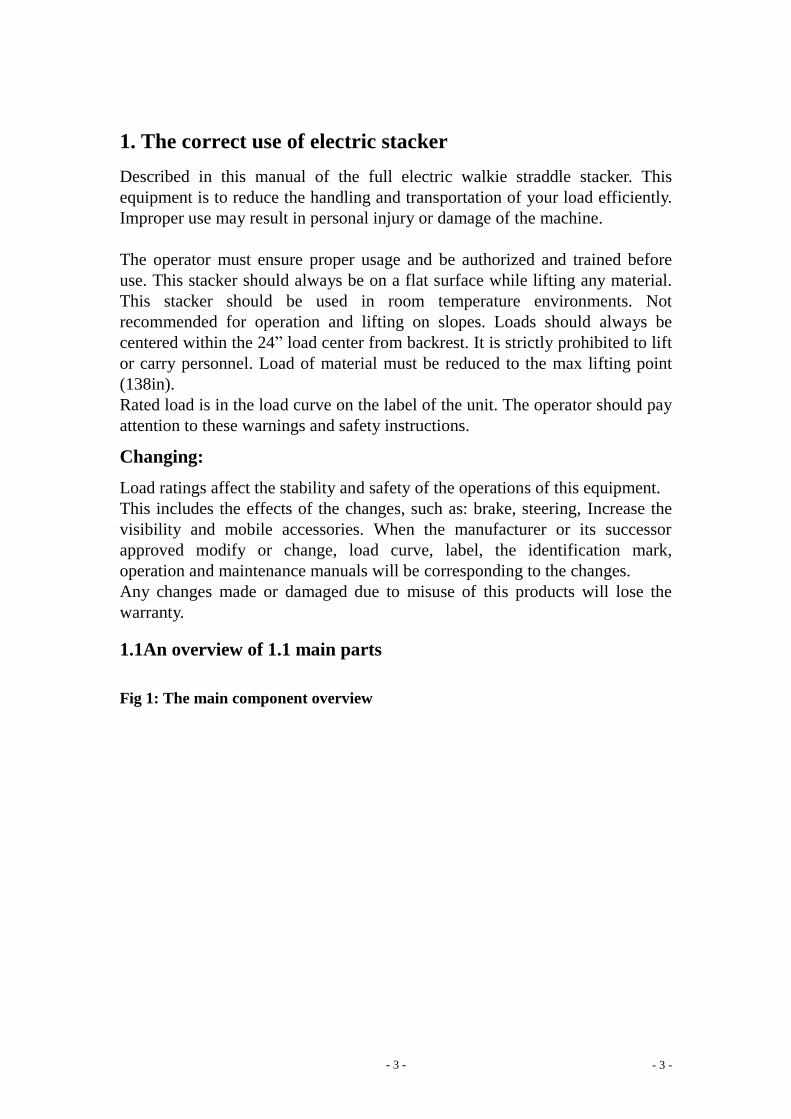
1. The correct use of electric stacker
Described in this manual of the full electric walkie straddle stacker. This
equipment is to reduce the handling and transportation of your load efficiently.
Improper use may result in personal injury or damage of the machine.
The operator must ensure proper usage and be authorized and trained before
use. This stacker should always be on a flat surface while lifting any material.
This stacker should be used in room temperature environments. Not
recommended for operation and lifting on slopes. Loads should always be
centered within the 24” load center from backrest. It is strictly prohibited to lift
or carry personnel. Load of material must be reduced to the max lifting point
(138in).
Rated load is in the load curve on the label of the unit. The operator should pay
attention to these warnings and safety instructions.
Changing:
Load ratings affect the stability and safety of the operations of this equipment.
This includes the effects of the changes, such as: brake, steering, Increase the
visibility and mobile accessories. When the manufacturer or its successor
approved modify or change, load curve, label, the identification mark,
operation and maintenance manuals will be corresponding to the changes.
Any changes made or damaged due to misuse of this products will lose the
warranty.
1.1An overview of 1.1 main parts
Fig 1: The main component overview
- 4 - - 4 -
1 3
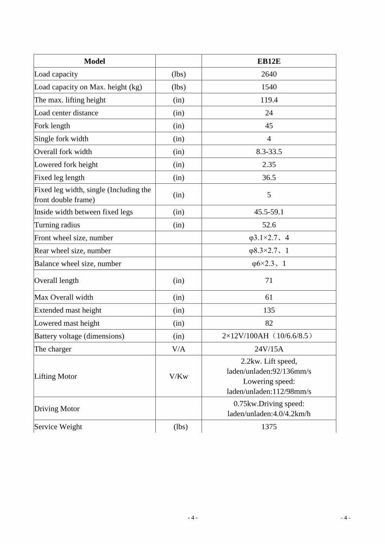
Model EB12E
Load capacity (lbs) 2640
Load capacity on Max. height (kg) (lbs) 1540
The max. lifting height (in) 119.4
Load center distance (in) 24
Fork length (in) 45
Single fork width (in) 4
Overall fork width (in) 8.3-33.5
Lowered fork height (in) 2.35
Fixed leg length (in) 36.5
Fixed leg width, single (Including the
front double frame) (in) 5
Inside width between fixed legs (in) 45.5-59.1
Turning radius (in) 52.6
Front wheel size, number φ3.1×2.7、4
Rear wheel size, number φ8.3×2.7、1
Balance wheel size, number φ6×2.3、1
Overall length (in) 71
Max Overall width (in) 61
Extended mast height (in) 135
Lowered mast height (in) 82
Battery voltage (dimensions) (in) 2×12V/100AH(10/6.6/8.5)
The charger V/A 24V/15A
Lifting Motor V/Kw
2.2kw. Lift speed,
laden/unladen:92/136mm/s
Lowering speed:
laden/unladen:112/98mm/s
Driving Motor 0.75kw.Driving speed:
laden/unladen:4.0/4.2km/h
Service Weight (lbs) 1375
- 5 - - 5 -
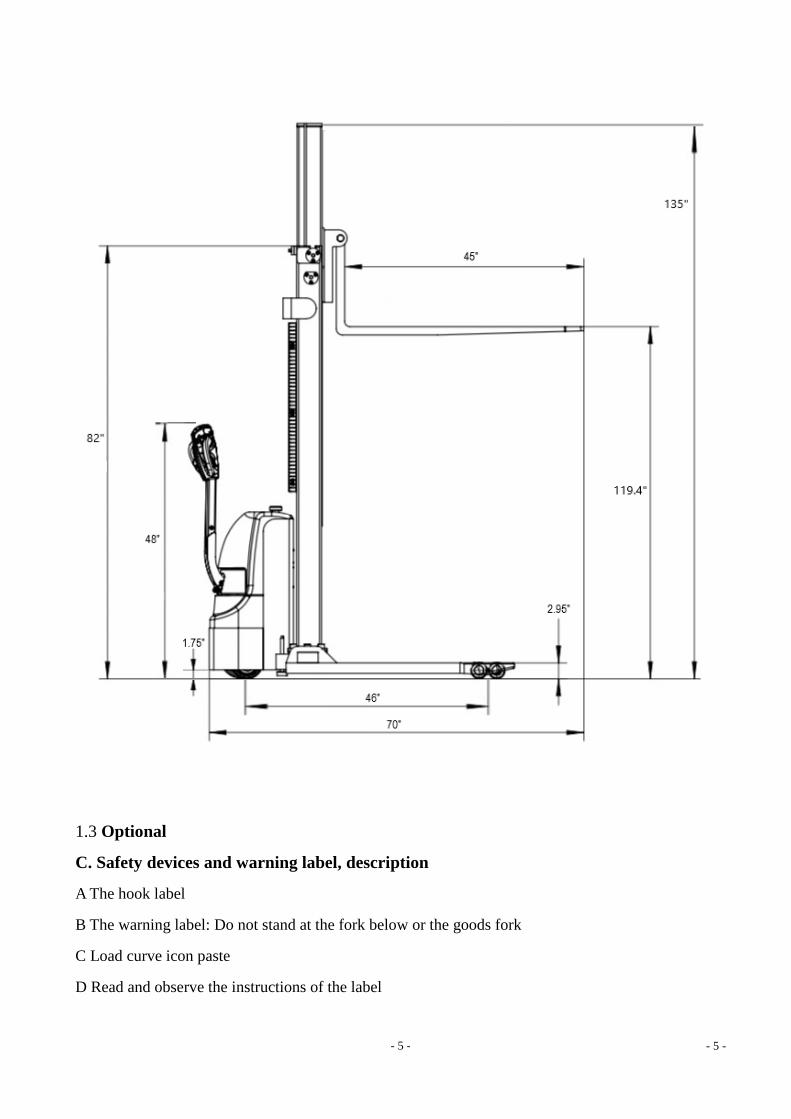
1.3 Optional
C. Safety devices and warning label, description
A The hook label
B The warning label: Do not stand at the fork below or the goods fork
C Load curve icon paste
D Read and observe the instructions of the label
- 6 - - 6 -
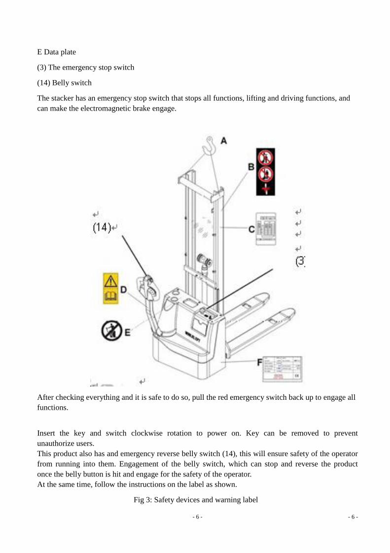
E Data plate
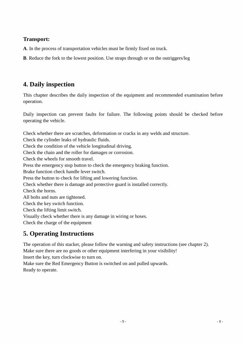
(3) The emergency stop switch
(14) Belly switch
The stacker has an emergency stop switch that stops all functions, lifting and driving functions, and
can make the electromagnetic brake engage.
After checking everything and it is safe to do so, pull the red emergency switch back up to engage all
functions.
Insert the key and switch clockwise rotation to power on. Key can be removed to prevent
unauthorize users.
This product also has and emergency reverse belly switch (14), this will ensure safety of the operator
from running into them. Engagement of the belly switch, which can stop and reverse the product
once the belly button is hit and engage for the safety of the operator.
At the same time, follow the instructions on the label as shown.
Fig 3: Safety devices and warning label
- 7 - - 7 -
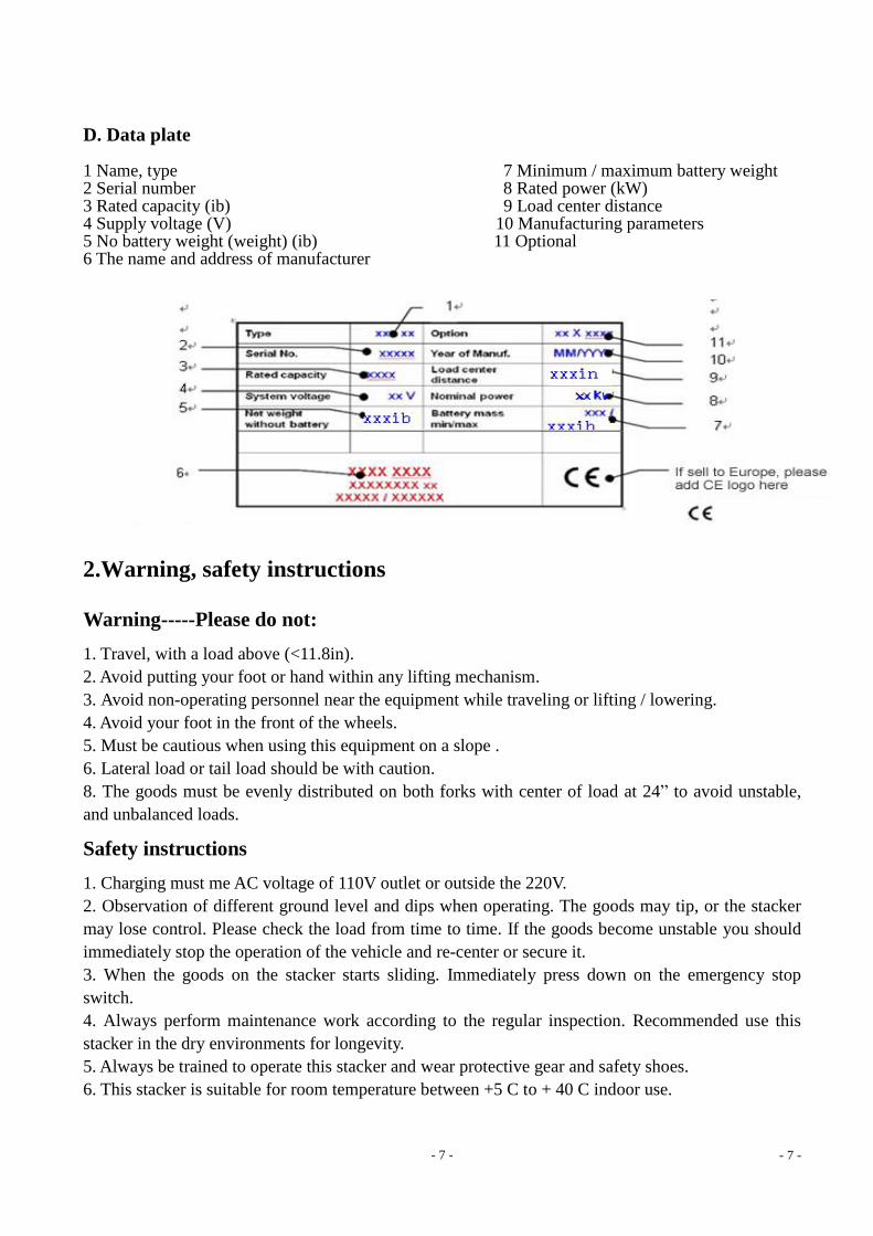
D. Data plate 1 Name, type 7 Minimum / maximum battery weight 2 Serial number 8 Rated power (kW) 3 Rated capacity (ib) 9 Load center distance 4 Supply voltage (V) 10 Manufacturing parameters 5 No battery weight (weight) (ib) 11 Optional 6 The name and address of manufacturer
2.Warning, safety instructions
Warning-----Please do not:
1. Travel, with a load above (<11.8in).
2. Avoid putting your foot or hand within any lifting mechanism.
3. Avoid non-operating personnel near the equipment while traveling or lifting / lowering.
4. Avoid your foot in the front of the wheels.
5. Must be cautious when using this equipment on a slope .
6. Lateral load or tail load should be with caution.
8. The goods must be evenly distributed on both forks with center of load at 24” to avoid unstable,
and unbalanced loads.
Safety instructions
1. Charging must me AC voltage of 110V outlet or outside the 220V.
2. Observation of different ground level and dips when operating. The goods may tip, or the stacker
may lose control. Please check the load from time to time. If the goods become unstable you should
immediately stop the operation of the vehicle and re-center or secure it.
3. When the goods on the stacker starts sliding. Immediately press down on the emergency stop
switch.
4. Always perform maintenance work according to the regular inspection. Recommended use this
stacker in the dry environments for longevity.
5. Always be trained to operate this stacker and wear protective gear and safety shoes.
6. This stacker is suitable for room temperature between +5 C to + 40 C indoor use.
- 8 - - 8 -
7. Be cautious while operating this on a slope. Sudden movement may cause unexpected stability of
the load.
3. Inspection, transport, outage
3.1 Test
Inspecting on receipt of your new stacker, the following steps before operating the equipment: The
equipment should be at full charge. (see Chapter sixth) Work according to the inspection and routine
inspection of the equipment.
3.2 Lifting / Transport.
When transporting, the removal of the goods, the fork must be lowered to the lowest position, and
according to the following chart secure equipment.
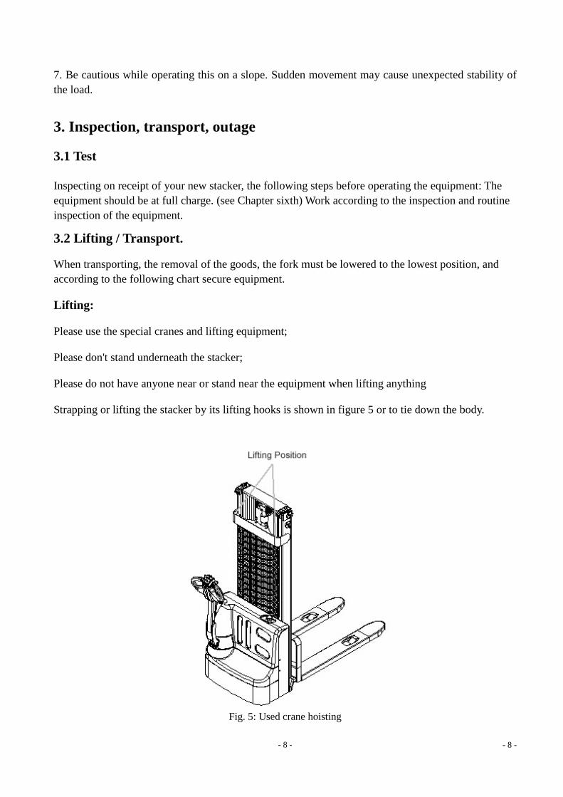
Lifting:
Please use the special cranes and lifting equipment;
Please don't stand underneath the stacker;
Please do not have anyone near or stand near the equipment when lifting anything
Strapping or lifting the stacker by its lifting hooks is shown in figure 5 or to tie down the body.
Fig. 5: Used crane hoisting
- 9 - - 9 -
Transport:
A. In the process of transportation vehicles must be firmly fixed on truck.
B. Reduce the fork to the lowest position. Use straps through or on the outriggers/leg
4. Daily inspection
This chapter describes the daily inspection of the equipment and recommended examination before
operation.
Daily inspection can prevent faults for failure. The following points should be checked before
operating the vehicle.
Check whether there are scratches, deformation or cracks in any welds and structure.
Check the cylinder leaks of hydraulic fluids.
Check the condition of the vehicle longitudinal driving.
Check the chain and the roller for damages or corrosion.
Check the wheels for smooth travel.
Press the emergency stop button to check the emergency braking function.
Brake function check handle lever switch.
Press the button to check for lifting and lowering function.
Check whether there is damage and protective guard is installed correctly.
Check the horns.
All bolts and nuts are tightened.
Check the key switch function.
Check the lifting limit switch.
Visually check whether there is any damage in wiring or hoses.
Check the charge of the equipment
5. Operating Instructions
The operation of this stacker, please follow the warning and safety instructions (see chapter 2).
Make sure there are no goods or other equipment interfering in your visibility!
Insert the key, turn clockwise to turn on.
Make sure the Red Emergency Button is switched on and pulled upwards.
Ready to operate.
- 10 - - 10 -
5.1 Parking
Not recommended to stop on a slope.
This car is equipped with an electromagnetic fault protection parking and parking brake.
However, please always completely lower the fork at all times. Turn key counterclockwise rotation,
then remove the key.
5.2 Load Curve
Load curve shows a given load center C [mm] and horizontal load capacity of the largest load Q [kg]
vehicle corresponding lifting height is H [mm].
The white mark on the door frame representation can reach ascension range.
For example: a cargo gravity center distance of C is 24”, the maximum lifting height H
119in, the maximum load capacity of Q to 1540lbs.
5.3 Lifting Loads
Do not overload. The maximum load capacity of this car is 1540lbs at max height.
Only increase the load capacity allowed by the load curve.
When traveling, lower the fork to 11.8in to reduce to a car on the leg, and press the lift button (Figure
1, 11) until you reach your expectations lifting height.
5.4 Lowering Loads
Always lower the loads slowly and carefully without any shifting or turning. Carefully press the
down button, then carefully pull away from the goods.
5.5 Traveling
Always travel with slower speeds with loads and when going up ramps have the load facing forward.
Travel with caution and awareness of your surroundings.
Always lower your load to a minimum when traveling.
- 11 - - 11 -
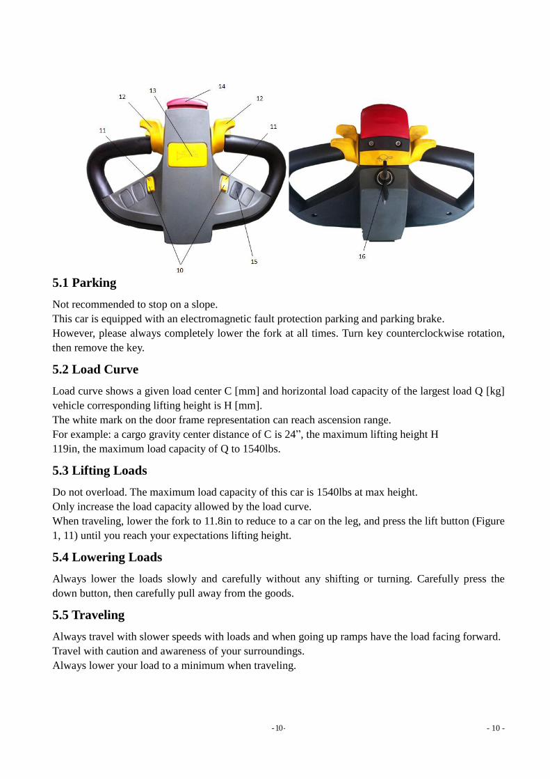
Fig 7: Goods Up
Turn on the equipment with key, pull the emergency button switch upward if not engaged. Raise the
forks at a minimum height of at least 3-6 inches off the ground to avoid getting caught up on
anything (Figure 11)
Carefully accelerator butterfly throttle on the handle to determine if you are moving forward or
backwards. (Figure 12).
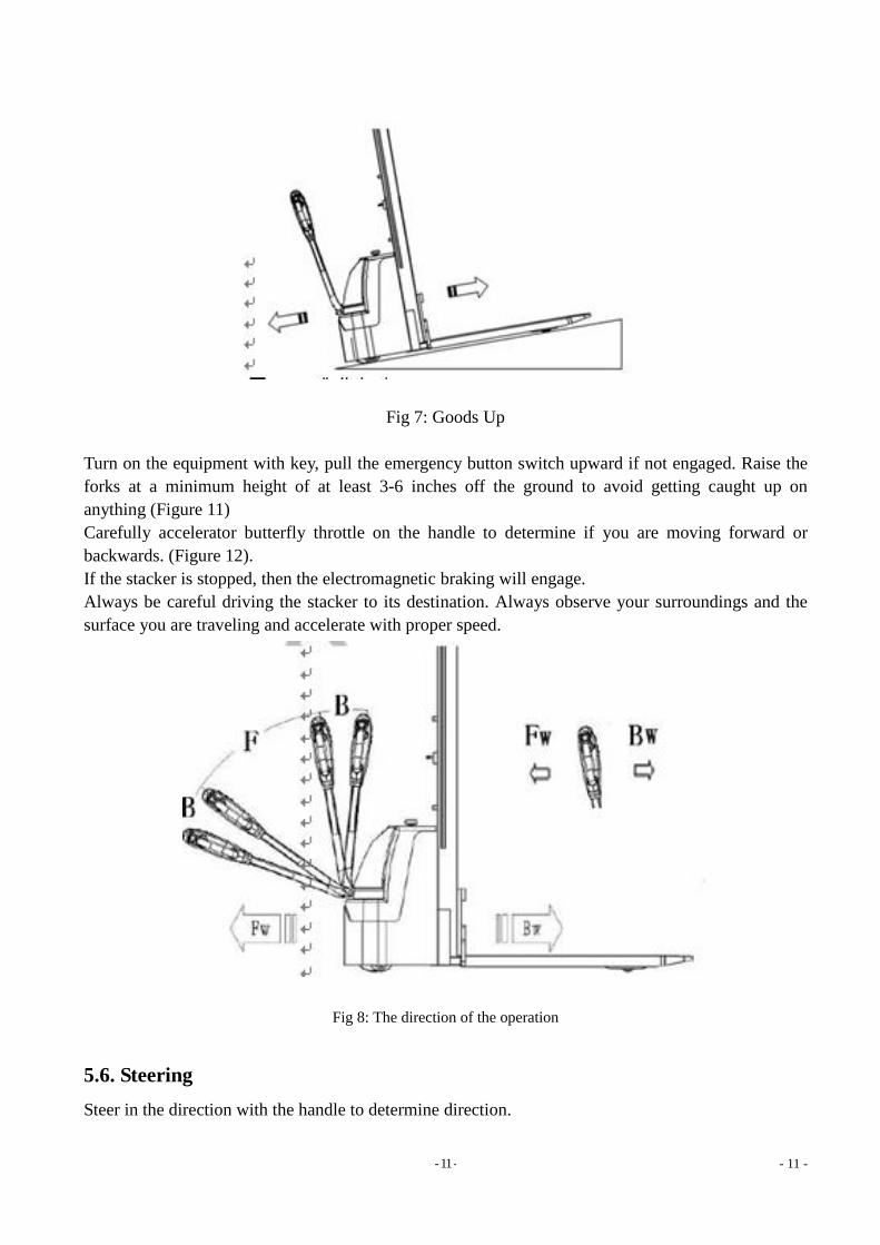
If the stacker is stopped, then the electromagnetic braking will engage.
Always be careful driving the stacker to its destination. Always observe your surroundings and the
surface you are traveling and accelerate with proper speed.
Fig 8: The direction of the operation
5.6. Steering
Steer in the direction with the handle to determine direction.
- 12 - - 12 -
5.7. Brake
Load braking performance depends on the road conditions and equipment.
Brake function can be activated by the following ways through the accelerator button (12) moved
back to '0' position or the release of this button, the regenerative braking is activated.
Through the accelerator button (12) driving direction move directly to the opposite direction from a
truck with regenerative braking, until it begins running in the opposite direction.
If the handle is moved upwards or downwards to the braking zone ('B'), truck will stop. If the release
lever, is automatically moved to the handle braking area ('B'). The truck will start braking.
Belly button switch (14) can prevent accidents and will stop and reverse once the belly button switch
is engaged. If you press this switch, the truck will reverse in opposite direction ('Bw.”), then stop to
avoid accidents. If the handle on the operation of the truck is not running, properly, please consider
this switch is compressed.
5.8. Fault
If there is any fault or truck is not operating properly, please stop using the truck and press the
emergency stop switch (2).
Park the truck in a safe area, turn the ignition off (16) counter clockwise rotation, and then pull out
the key.
Immediately inform the manager and / or contact your customer service personnel. If necessary,
transport the truck with another lifting equipment to a secure location to diagnose.
5.9 In case of emergency
When you encounter an emergency, press down the emergency stop switch (2). All electrical
functions will stop. Keep a safe distance.
6. Battery charging and replacement
1. Only qualified technicians or trained operators should repair or to recharge the battery. Please be
sure to abide by the operation manual and battery manufacturer's instructions.
2. These batteries are maintenance free, prohibited to for re-fill.
3. Battery recycling shall abide by state laws and regulations due to hazardous material and
chemicals. Please abide by these provisions.
4. Treatment of the battery, the prohibition of the use of fire, gas may cause explosion!
5. Battery charging areas should be free from flammable materials or flammable liquids. Smoking is
prohibited, and the area must be well ventilated.
6. Truck must be parked with the equipment with the emergency button off before charging or
installing replacement battery.
7. Before performance maintenance, make sure all wiring harness is connected correctly.
8. The truck is equipped with a sealed liquid acid battery 2*12V/ 100Ah.
9. Only allow the use of sealed lead-acid battery for operation of this truck.
Note: Please consider the maximum operating temperature of the battery.
6.1. Replacement
- 13 - - 13 -
Safety park vehicles, with a key (16) close the stacker and press the emergency stop switch (2).
Unscrew the 2 screws on the main cover, remove the main outer cover. First unscrew the
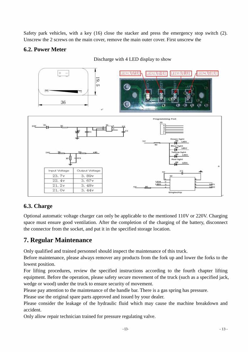
6.2. Power Meter
Discharge with 4 LED display to show
6.3. Charge
Optional automatic voltage charger can only be applicable to the mentioned 110V or 220V. Charging
space must ensure good ventilation. After the completion of the charging of the battery, disconnect
the connector from the socket, and put it in the specified storage location.
7. Regular Maintenance
Only qualified and trained personnel should inspect the maintenance of this truck.
Before maintenance, please always remover any products from the fork up and lower the forks to the
lowest position.
For lifting procedures, review the specified instructions according to the fourth chapter lifting
equipment. Before the operation, please safety secure movement of the truck (such as a specified jack,
wedge or wood) under the truck to ensure security of movement.
Please pay attention to the maintenance of the handle bar. There is a gas spring has pressure.
Please use the original spare parts approved and issued by your dealer.
Please consider the leakage of the hydraulic fluid which may cause the machine breakdown and
accident.
Only allow repair technician trained for pressure regulating valve.
- 14 - - 14 -
If you need to replace the wheel, please follow the above instructions. Caster must be and no
abnormal wear round.
Check and maintain the list of items on the list.
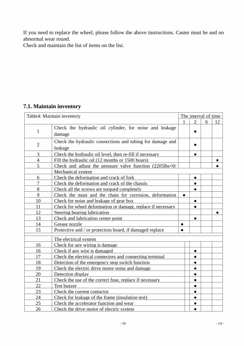
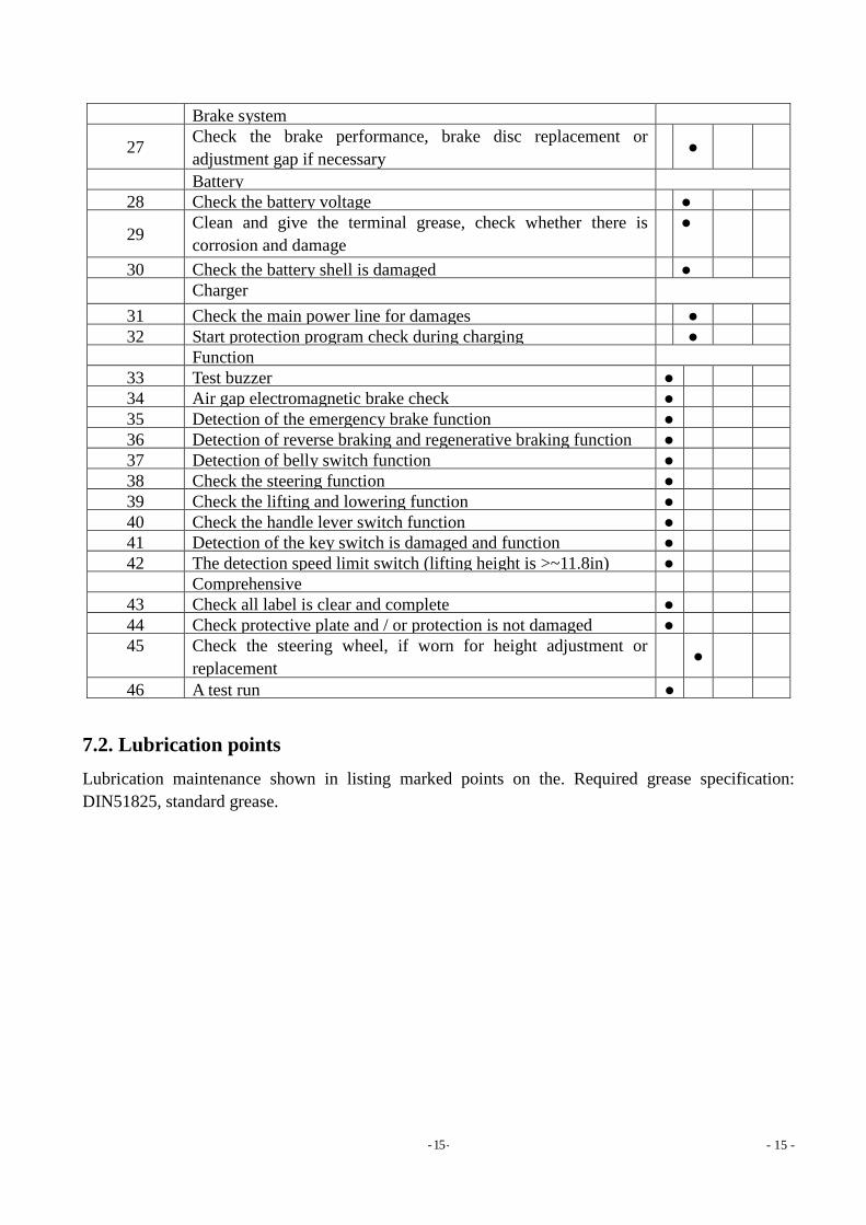
7.1. Maintain inventory
Table4: Maintain inventory
The interval of time
(month)
1 2 6 12
1 Check the hydraulic oil cylinder, for noise and leakage
damage ●
2 Check the hydraulic connections and tubing for damage and
leakage
●
3 Check the hydraulic oil level, then re-fill if necessary
●
4 Fill the hydraulic oil (12 months or 1500 hours)
●
5 Check and adjust the pressure valve function (2205lbs+0/
+10%)
●
Mechanical system
6 Check the deformation and crack of fork
●
7 Check the deformation and crack of the chassis
●
8 Check all the screws are torqued completely
●
9 Check the mast and the chain for corrosion, deformation
damage, replace if necessary
●
10 Check for noise and leakage of gear box
●
11 Check for wheel deformation or damage, replace if necessary
●
12 Steering bearing lubrication
●
13 Check and lubrication center point
●
14 Grease nozzle
●
15 Protective and / or protection board, if damaged replace
●
15
The electrical system
16 Check for any wiring is damage
16 Check if any wire is damaged
●
17 Check the electrical connectors and connecting terminal
●
18 Detection of the emergency stop switch function
●
19 Check the electric drive motor noise and damage
●
20 Detection display
●
21 Check the use of the correct fuse, replace if necessary
●
22 Test buzzer
●
23 Check the current contactor
●
24 Check for leakage of the frame (insulation test)
●
25 Check the accelerator function and wear
●
26 Check the drive motor of electric system ●
- 15 - - 15 -
Brake system
27 Check the brake performance, brake disc replacement or
adjustment gap if necessary
●
Battery
28 Check the battery voltage
●
29 Clean and give the terminal grease, check whether there is
corrosion and damage
●
30 Check the battery shell is damaged
●
Charger
31 Check the main power line for damages
●
32 Start protection program check during charging
●
Function
33 Test buzzer
●
34 Air gap electromagnetic brake check
●
35 Detection of the emergency brake function
●
36 Detection of reverse braking and regenerative braking function
●
37 Detection of belly switch function
●
38 Check the steering function
●
39 Check the lifting and lowering function
●
40 Check the handle lever switch function
●
41 Detection of the key switch is damaged and function
●
42 The detection speed limit switch (lifting height is >~11.8in)
●
Comprehensive
43 Check all label is clear and complete
●
44 Check protective plate and / or protection is not damaged
●
45 Check the steering wheel, if worn for height adjustment or
replacement
●
46 A test run
●
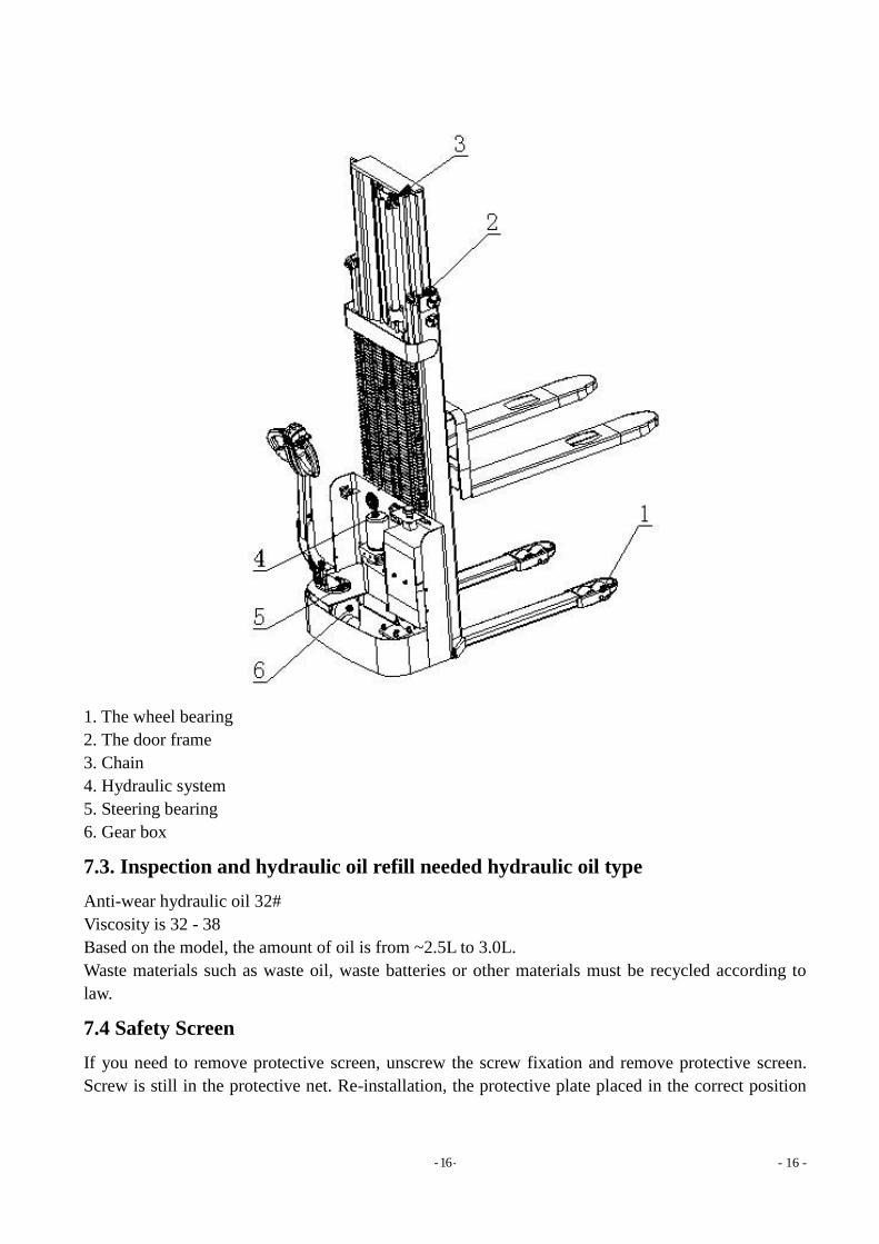
7.2. Lubrication points
Lubrication maintenance shown in listing marked points on the. Required grease specification:
DIN51825, standard grease.
- 16 - - 16 -
1. The wheel bearing
2. The door frame
3. Chain
4. Hydraulic system
5. Steering bearing
6. Gear box
7.3. Inspection and hydraulic oil refill needed hydraulic oil type
Anti-wear hydraulic oil 32#
Viscosity is 32 - 38
Based on the model, the amount of oil is from ~2.5L to 3.0L.
Waste materials such as waste oil, waste batteries or other materials must be recycled according to
law.
7.4 Safety Screen
If you need to remove protective screen, unscrew the screw fixation and remove protective screen.
Screw is still in the protective net. Re-installation, the protective plate placed in the correct position
- 17 - - 17 -
and then tighten screws. If you need to change parts, please contact your nearest after sale service
dealer.
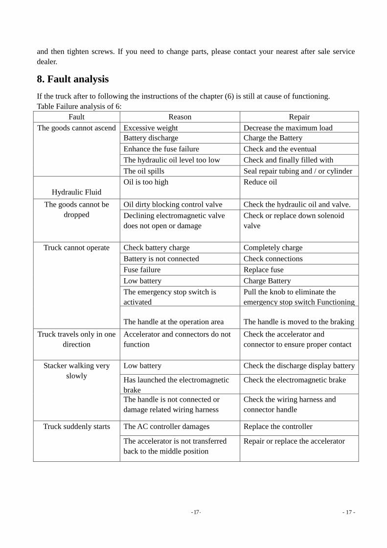
8. Fault analysis
If the truck after to following the instructions of the chapter (6) is still at cause of functioning.
Table Failure analysis of 6:
Fault Reason
Repair
The goods cannot ascend
Excessive weight
Decrease the maximum load
capacity is shown on the nameplate
Battery discharge
Charge the Battery
Enhance the fuse failure
Check and the eventual
replacement of ascending fuse
The hydraulic oil level too low
Check and finally filled with
hydraulic oil
The oil spills
Seal repair tubing and / or cylinder
Hydraulic Fluid
Oil is too high
Reduce oil
The goods cannot be
dropped
Oil dirty blocking control valve
Check the hydraulic oil and valve.
Replace the hydraulic oil if
necessary
Declining electromagnetic valve
does not open or damage
Check or replace down solenoid
valve
Truck cannot operate
Check battery charge
Completely charge
Battery is not connected
Check connections
Fuse failure
Replace fuse
Low battery
Charge Battery
The emergency stop switch is
activated
Pull the knob to eliminate the
emergency stop switch Functioning
The handle at the operation area
The handle is moved to the braking
zone
Truck travels only in one
direction
Accelerator and connectors do not
function
Check the accelerator and
connector to ensure proper contact
Stacker walking very
slowly
Low battery
Check the discharge display battery
Has launched the electromagnetic
brake
Check the electromagnetic brake
The handle is not connected or
damage related wiring harness
Check the wiring harness and
connector handle
Truck suddenly starts
The AC controller damages
Replace the controller
The accelerator is not transferred
back to the middle position
Repair or replace the accelerator