Eaton VVS-VVP Catalogue2
38
VVS/VVP Series Vane Pumps Technical Catalog Variable Displacement, For Industrial Applications
-
Upload
nguyentuong -
Category
Documents
-
view
273 -
download
0
Transcript of Eaton VVS-VVP Catalogue2

VVS/VVP Series Vane Pumps
Technical CatalogVariable Displacement,For IndustrialApplications

2
Contents
Introduction................................................................................................................................................................. Page 3
Sectional Views and Functional Symbols................................................................................................................ Page 4
Series VVS Pumps
Model Code.............................................................................................................................................. Page 5
Technical Data...........................................................................................................................................Page 6
Performance Characteristics
VVS0............................................................................................................................................... Page 7
VVS1............................................................................................................................................... Page 8
VVS2............................................................................................................................................... Page 9
VVS3............................................................................................................................................... Page 10
Installation Dimensions
VVS0............................................................................................................................................... Page 11
VVS1............................................................................................................................................... Page 12
VVS2 & VVS3..................................................................................................................................Page 13
Series VVP Pumps
Model Code.............................................................................................................................................. Page 15
Technical Data...........................................................................................................................................Page 16
Controls
Pressure Regulation........................................................................................................................Page 17
Load Sensing and Pressure Regulation..........................................................................................Page 18
Pressure Regulation with Torque Sensing......................................................................................Page 20
Performance Characteristics
VVP1............................................................................................................................................... Page 21
VVP2............................................................................................................................................... Page 22
VVP3............................................................................................................................................... Page 23
Installation Dimensions
VVP1............................................................................................................................................... Page 24
VVP2 & VVP3..................................................................................................................................Page 25
Series VVS and VVP Pumps
Installation Dimensions - Base Mounted Pumps......................................................................................Page 27
Combined Pumps
Pump Combinations................................................................................................................................. Page 28
Torque Requirements............................................................................................................................... Page 30
Installation Dimensions.............................................................................................................................Page 31
Key Lock Adjustment..................................................................................................................................................Page 35
Mounting, Shaft and Port Dimensions..................................................................................................................... Page 36
Installation Instructions..............................................................................................................................................Page 37
EATON Vickers VVS/VVP Variable Displacement Vane Pumps V-PUVN-TM002-E August 2004
3
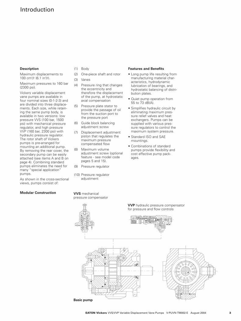
Introduction
Basic pump
VVP hydraulic pressure compensatorfor pressure and flow controls
VVS mechanicalpressure compensator
Modular Construction
EATON Vickers VVS/VVP Variable Displacement Vane Pumps V-PUVN-TM002-E August 2004
Description
Maximum displacements to100 cm3/r (6.1 in3/r).
Maximum pressures to 160 bar(2300 psi).
Vickers variable displacementvane pumps are available infour nominal sizes (0-1-2-3) andare divided into three displace-ments. Each size, while retain-ing the same pump body, isavailable in two versions: lowpressure VVS (100 bar, 1500psi) with mechanical pressureregulator, and high pressureVVP (160 bar, 2300 psi) withhydraulic pressure regulator.The rotor shaft of Vickerspumps is pre-arranged formounting an additional pump.By removing the rear cover, thesecondary pump can be easilyattached (see items A and B onpage 4). Combining standardpumps eliminates the need formany “special application”pumps.
As shown in the cross-sectionalviews, pumps consist of:
(1) Body
(2) One-piece shaft and rotor
(3) Vanes
(4) Pressure ring that changesthe eccentricity and therefore the displacementof the pump, at hydrostaticaxial compensation
(5) Pressure plate stator to provide the passage of oil from the suction port to the pressure port
(6) Guide block balancing adjustment screw
(7) Displacement adjustment piston that regulates the maximum pressure compensated flow
(8) Maximum volume adjustment screw (optionalfeature - see model code pages 5 and 15).
(9) Pressure regulator
(10) Pressure regulator adjustment
Features and Benefits
• Long pump life resulting frommanufacturing material char-acteristics, hydrodynamiclubrication of bearings, andhydrostatic balancing of distri-bution plates.
• Quiet pump operation from55 to 73 dB(A).
• Simplifies hydraulic circuit byeliminating maximum pres-sure relief valves and heatexchangers. Pumps can besupplied with various pres-sure regulators to control themaximum system pressure.
• Standard ISO and SAEmountings.
• Combinations of standardpumps provide flexibility andcost effective pump pack-ages.

P
Sections andSymbols
4 EATON Vickers VVS/VVP Variable Displacement Vane Pumps V-PUVN-TM002-E August 2004
VVP PumpSee description on page 3.
VVS PumpSee description on page 3.
P

5EATON Vickers VVS/VVP Variable Displacement Vane Pumps V-PUVN-TM002-E August 2004
Variable Vane Pump
Frame Size / Max. Pressure
0 - 6.3, 10, 12.5 cm3/rMax. pressure 150 bar (2200 psi)
1 - 16, 20, 25 cm3/rMax. pressure 100 bar (1500 psi)
2 - 31.5, 40, 50 cm3/rMax. pressure 100 bar (1500 psi)
3 - 63, 80, 100 cm3/rMax. pressure 80 bar (1200 psi)
Nominal Size /Geometric Displacement
06 - 6.3 cm3/r (0.38 in3/r)10 - 10 cm3/r (0.61 in3/r)12 - 12.5 cm3/r (0.76 in3/r)16 - 16 cm3/r (0.98 in3/r)20 - 20 cm3/r (1.22 in3/r)25 - 25 cm3/r (1.53 in3/r)32 - 31.5 cm3/r (1.92 in3/r)40 - 40 cm3/r (2.44 in3/r)50 - 50 cm3/r (3.05 in3/r)63 - 63 cm3/r (3.84 in3/r)80 - 80 cm3/r (4.88 in3/r)100 - 100 cm3/r (6.10 in3/r)
Adjust. Max. Displacement Stop
S - With stop(Omit if not required.)
Rotation Viewed FromShaft End
R - Right hand(clockwise) only
Fluid Compatibility
M - Mineral oilE - Phosphate esters
Pump Design Number
30 - All models exceptSubject to change. Installationdimensions remain unaltered fordesigns *0-*9.
Pressure Control
C - Standard pressure compensator
Control Pressure Setting
A - 15-50 bar (215-700 psi)(all frame sizes)
B - 30-80 bar (430-1200 psi) (frame size 3)
C - 30-100 bar (430-1500 psi) (frame sizes 0, 1 and 2)
D - 80-150 bar (1200-2200 psi)(frame size 0)
Adjustment Device
W - Screw with locknutKL - Screw with key lock
Control Design Number
10 - For all models.Subject to change. Installationdimensions remain unaltered fordesigns 10-19.
Special Features Suffix
Mounting Flange / Port Connections
Code Frame Size Mounting flange Port connectionsR Size 0 or 1 ISO 3019/2 with straight G (BSPF) thread.
keyed shaft (size 0 is only available as a single or secondary pump)
RF Size 2 or 3 ISO 3019/2 with straight SAE 4-bolt flange with keyed shaft metric mounting bolts
PS Size 0 ISO 3019/2 with straight keyed shaft (for size0 pumps only). Size 0 isonly available as a singleor secondary pump.
Size 1 SAE B 4-bolt with straight keyed shaft (for size 1 pumps only)
PF Size 2 or 3 SAE C 2-bolt with straight SAE 4-bolt flange withkeyed shaft (only available UNC mounting boltson a primary or single pump)
PX Size 2 or 3 ISO 3019/2 with straight SAE 4-bolt flange with keyed shaft (available UNC mounting boltsonly on secondary pump)
B Sizes 1, 2 or 3 Base plate mounting O-ring sealed (available only assingle pump)
Note: See page 36 for detailed dimensional listing for mounting flanges,shafts and ports.
1
2
3
4
5
7
6
8
10
11
12
13
9
SAE UNF thread.
Model CodeVVS Series

Nominal size Size 0 Size 1 Size 2 Size 3Displacement according to ISO 3662 - cm3/r (in3/r) 6.3 (0.384) 16 (0.976) 31.5 (1.922) 63 (3.844)
10 (0.610) 20 (1.220) 40 (2.441) 80 (4.882)12.5 (0.763) 25 (1.526) 50 (3.051) 100 (6.102)
Actual displacement - cm3/r (in3/r) 6.9 (0.421) 17.9 (1.092) 34.5 (2.105) 69 (4.211)11 (0.671) 22.1 (1.349) 42.8 (2.612) 86.2 (5.260)13.1 (0.799) 26.9 (1.642) 53.1 (3.240) 105.5 (6.438)
Mounting flange type (See model code, page 5.) ISO 3019/2 ISO 3019/2 ISO 3019/2 ISO 3019/24-bolt 4-bolt SAE C 2-bolt SAE C 2-bolt
Base plate Base plate Base plateMaximum working pressure - bar (psi) 150 (2200) 100 (1500) 100 (1500) 80 (1200)Allowed maximum drain port pressure - bar (psi)Inlet pressure (absolute) - bar (psi)Speed range - r/minRotation direction (viewed from shaft end)Loads on drive shaftMaximum torque on primary shaft - Nm (lbf-in) 110 (974) 197 (1744) 400 (3540) 740 (6550)(See pages 28 and 30 for torque requirements ofcombined pumps.) Hydraulic fluid
Viscosity range at working temperature - mm2/s (cSt) Recommended viscosity - mm2/s (cSt) at 50°C (122°F)Viscosity indexFluid temperature range - °C (°F)Maximum fluid contamination levelWeight - kg (lb) 6.5 (14.3) 12 (26.5) 32 (70.5) 44 (97)In case of different operating conditions, contact Eaton Hydraulics.
Technical DataVVS Series
6 EATON Vickers VVS/VVP Variable Displacement Vane Pumps V-PUVN-TM002-E August 2004
1 (14.5)0.8-1.5[11.6-21.8]
800 to 1800Right-hand (clockwise)
No radial or axial loads allowed
Mineral oil - HM according to ISO 6743/4 - HLP accordingto DIN 51524/2
Organic ester HFD-V according to ISO 6743/4 (QUINTOLUT-SRIC N822-300)
23 to 6832
100 minimum-10/+50 [14/122]
Class 9 per NAS 1638, or class 18/16/13 per ISO 4406

7
PerformanceCharacteristicsVVS0
EATON Vickers VVS/VVP Variable Displacement Vane Pumps V-PUVN-TM002-E August 2004
Performance with:
Speed 1450 r/min
Oil per ISO 6743/4
Viscosity 32 mm2/s (cSt)
Temperature 50°C (122°F)
3 (0.79)
6 (1.59)
9 (2.38)
12 (3.17)
15 (3.96)
18 (4.76)
21 (5.55)
1.5 (2.01)
3 (4.02)
4.5 (6.03)
6 (8.05)
25(350)
50(700)
75(1100)
100(1500)
125(1850)
150(2200)
0
Operating pressure - bar (psi)
Inpu
t pow
er -
kW (h
p)
Flow
- L/
min
(USg
pm)
25(350)
50(700)
75(1100)
100(1500)
125(1850)
150(2200)
0
3 (0.79)
6 (1.59)
9 (2.38)
12 (3.17)
15 (3.96)
18 (4.76)
21 (5.55)
1.5 (2.01)
3 (4.02)
4.5 (6.03)
6 (8.05)
Flow
- L/
min
(USg
pm)
Operating pressure - bar (psi)
Inpu
t pow
er -
kW (h
p)
2 (0.53)
4 (1.06)
6 (1.59)
8 (2.11)
10 (2.64)
12 (3.17)
14 (3.70)
Flow
- L/
min
(USg
pm)
25(350)
50(700)
75(1100)
100(1500)
125(1850)
150(2200)
0
Operating pressure - bar (psi)
1 (1.34)
2 (2.68)
3 (4.02)
4 (5.36)
Inpu
t pow
er -
kW (h
p)
0
6-10-12
time ms 50 ms
pres
sure
bar
(ps
i)
250 (3626)
200 (2901)
150 (2176)
100 (1450)
50 (7250
58
560
dB(A
)
62
60
64
6-10-1266
68
pressure bar (psi)(1450)(725)(363) (1088)
75(2176)(1813)
5025 100 125 150
pressure bar (psi)
(1450)100
(363)25
(725)50
(1088)75
(1813)125
(2176)150
drai
nage
l/m
in (
USg
pm)
2.5 (0.66)
2 (0.53)
1.5 (0.40)
1 (0.26)
0.5 (0.13)
0
6-10-12
VVS0-06
VVS0-10
VVS0-12
VVS0-06, -10, -12Values established with zero flow setting
VVS0-06, -10, -12Maximum noise level measured with sound-level meter placed at1 meter [39.37”] from pump, flexible coupling.
VVS0-06, -10, -12Response time and pressure peak
Power consumption withmaximum flow
Power consumption with zeroflow setting

8 EATON Vickers VVS/VVP Variable Displacement Vane Pumps V-PUVN-TM002-E August 2004
PerformanceCharacteristicsVVS1
Performance with:
Speed 1450 r/min
Oil per ISO 6743/4
Viscosity 32 mm2/s (cSt)
Temperature 50°C (122°F)
Flow
- L/
min
(USg
pm)
10 (2.64)
40 (10.57)
20 (5.28)
30 (7.93)
Inpu
t pow
er -
kW (h
p)
3 (4.02)4 (5.36)
1 (1.34)2 (2.68)
5 (6.71)6 (8.05)7 (9.39)
8 (10.73)
20(300)
40(600)
60(900)
80(1200)
100(1500)
0
Operating pressure - bar (psi)
Flow
- L/
min
(USg
pm)
35 (9.25)
10 (2.64)
15 (3.96)
20 (5.28)
25 (6.60)
30 (7.93)
3 (4.02)4 (5.36)
1 (1.34)2 (2.68)
5 (6.71)6 (8.05)
Inpu
t pow
er -
kW (h
p)7 (9.39)
0 100(1500)
20(300)
40(600)
60(900)
80(1200)
Operating pressure - bar (psi)
3 (4.02)4 (5.36)
100(1500)
20(300)
40(600)
60(900)
80(1200)
0
5 (1.32)
10 (2.64)
15 (3.96)
20 (5.28)
25 (6.60)
30 (7.93)
1 (1.34)2 (2.68)
Flow
- L/
min
(USg
pm)
Inpu
t pow
er -
kW (h
p)
5 (6.71)6 (8.05)
Operating pressure - bar (psi)
pres
sure
bar
(ps
i)
100 (1450)
0
50 (725)
150 (2176)
200 (2901)
250 (3626)
time ms 50 ms
16-20-25
0
pressure bar (psi)
66
62
64
60
16-20-2568
70
58
(290) (580) (1160)(870) (1450)20 40 60 80 100
dB(A
)
drai
nage
l/m
in (
USg
pm)
0
pressure bar (psi)
20
16-20-25
1.5 (0.40)
0.5 (0.13)
1 (0.26)
2 (0.53)
2.5 (0.66)
40 60 80 100(290) (580) (870) (1160) (1450)
VVS1-16
VVS1-20
VVS1-25
VVS1-16, -20, -25Values established with zero flow setting
VVS1-16, -20, -25Maximum noise level measured with sound-level meter placed at1 meter [39.37”] from pump, flexible coupling.
VVS1-16, -20, -25Response time and pressure peak
Power consumption withmaximum flow
Power consumption with zeroflow setting
9EATON Vickers VVS/VVP Variable Displacement Vane Pumps V-PUVN-TM002-E August 2004
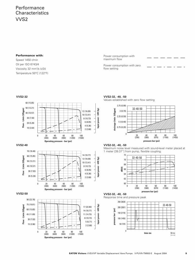
PerformanceCharacteristicsVVS2
Performance with:
Speed 1450 r/min
Oil per ISO 6743/4
Viscosity 32 mm2/s (cSt)
Temperature 50°C (122°F)
15 (3.96)
60 (15.85)
30 (7.93)
45 (11.89)
2 (2.68)
5 (6.71)
8 (10.73)
11 (14.75)
14 (18.77)
17 (22.80)
Flow
- L/
min
(USg
pm) 75 (19.81)
90 (23.78)
Inpu
t pow
er -
kW (h
p)
Operating pressure - bar (psi)
100(1500)
20(300)
40(600)
60(900)
80(1200)
0
4 (5.36)
2 (2.68)
6 (8.05)
8 (10.73)
10 (13.41)
12 (16.09)
14 (18.77)
Flow
- L/
min
(USg
pm)
Inpu
t pow
er -
kW (h
p)
50 (13.21)
40 (10.57)
20 (5.28)
30 (7.93)
60 (15.85)
70 (18.49)
Operating pressure - bar (psi)
100(1500)
20(300)
40(600)
60(900)
80(1200)
0
Operating pressure - bar (psi)
4 (5.36)2 (2.68)
6 (8.05)8 (10.73)
10 (13.41)12 (16.09)
100(1500)
20(300)
40(600)
60(900)
80(1200)
0
10 (2.64)
20 (5.28)
30 (7.93)
Inpu
t pow
er -
kW (h
p)
Flow
- L/
min
(USg
pm)
40 (10.57)
50 (13.21)
60 (15.85)
250 (3626)
200 (2901)
150 (2176)
50 (725)
100 (1450)
pres
sure
bar
(ps
i)
0time ms 50 ms
32-40-50
(1160)0
(290)20 60
(870)(580)40 80
(1450)100
32-40-50
60
62
64
66
68
72
70
dB(A
)
pressure bar (psi)
drai
nage
l/m
in (
USg
pm)
(1160)pressure bar (psi)
0(290)20
(870)60
(580)40 80
(1450)100
32-40-503 (0.79)
3.75 (0.99)
1.5 (0.40)
2.25 (0.59)
0.75 (0.20)
VVS2-32
VVS2-40
VVS2-50
VVS2-32, -40, -50Values established with zero flow setting
VVS2-32, -40, -50Maximum noise level measured with sound-level meter placed at1 meter [39.37”] from pump, flexible coupling.
VVS2-32, -40, -50Response time and pressure peak
Power consumption withmaximum flow
Power consumption with zeroflow setting

10 EATON Vickers VVS/VVP Variable Displacement Vane Pumps V-PUVN-TM002-E August 2004
PerformanceCharacteristicsVVS3
Performance with:
Speed 1450 r/min
Oil per ISO 6743/4
Viscosity 32 mm2/s (cSt)
Temperature 50°C (122°F)
0
Operating pressure - bar (psi)
60 (15.85)
30 (7.93)
90 (23.76)
Flow
- L/
min
(USg
pm)
120 (31.70)
150 (39.63)
180 (47.55)
20(300)
35(500)
50(700)
80(1200)
65(900)
5 (6.71)10 (13.41)15 (20.12)
20 (26.82)25 (33.53)
30 (40.23)
Inpu
t pow
er -
kW (h
p)
3 (4.02)
15 (20.12)
23 (30.84)
7 (9.39)11 (14.75)
19 (25.48)
0
25 (6.60)
50 (13.21)
75 (19.81)
Operating pressure - bar (psi)
20(300)
35(500)
50(700)
80(1200)
65(900)
100 (26.42)
125 (33.03)
150 (39.63)
Flow
- L/
min
(USg
pm)
Inpu
t pow
er -
kW (h
p)
20 (5.28)
40 (10.57)
60 (15.85)
3 (4.02)6 (8.05)
12 (16.09)
15 (20.12)
9 (12.07)
18 (24.14)
Inpu
t pow
er -
kW (h
p)
Flow
- L/
min
(USg
pm)
80 (21.13)
100 (26.42)
120 (31.70)
0
Operating pressure - bar (psi)
20(300)
35(500)
50(700)
80(1200)
65(900)
pres
sure
bar
(ps
i)
0time ms 50 ms
63-80-100260 (3771)
200 (2901)
140 (2031)
80 (1160)
20 (290)
0
dB(A
)
pressure bar (psi)
63-80-100
62
64
66
68
70
72
74
4020 60 80(290) (580) (870) (1160)
drai
nage
l/m
in (
USg
pm)
0
pressure bar (psi)
63-80-100
20 40 60 80
1 (0.26)
2 (0.53)
3 (0.79)
4 (1.06)
5 (1.32)
(290) (580) (870) (1160)
VVS3-63
VVS3-80
VVS3-100
VVS3-63, -80, -100Values established with zero flow setting
VVS3-63, -80, -100Maximum noise level measured with sound-level meter placed at1 meter [39.37”] from pump, flexible coupling.
VVS3-63, -80, -100Response time and pressure peak
Power consumption withmaximum flow
Power consumption with zeroflow setting

11EATON Vickers VVS/VVP Variable Displacement Vane Pumps V-PUVN-TM002-E August 2004
VVS0With ISOMounting FlangeInstallation Dimensionsin mm (in)
All mounting flange, port andshaft options are listed onpage 36.
3rd angleprojection
“C” ControlWith “KL” Adjustment
Drain port
Inlet port
B Outlet port
Pressure adjustment screw
Volume adjustment screw
¯ØK
¯ØD G
7 [0.276]
113 [4.449]
H
90 [3.543]
A 28 [1
.102
]
65 [2
.559
]
70 [2.756]
94 [3.701]
¯ØL
E
8 [0.315]
45 [1.772]
180
[7.0
87]
115
[4.5
28]
30 [1
.181
] max
.
F
35 [1.378]
Ø9 [0.354]
C
60 [2
.362
]90 [3.543]
55 [2.165]
MOUNTING FLANGE AND PORTS CODE� B C F G Ø D A H E Ø K Ø L
R 3/8” BSP 1/4” BSP 6 22.5 20 3/4” BSP 157 44 80 103(0.236) (0.886) (0.787) (6.18) (1.73) (3.150) (4.055)
PS 0.750-16 0.500-20 4.76 17.9 15.88 1.063-12 136 32 80 103UNF-2B UNF-2B (0.187) (0.705) (0.625) UNF-2B (5.35) (1.25) (3.150) (4.055)
� See model code, page 5.
60 [2
.362
]
170
[6.6
93]
Pressureadjustment knob.Turning clockwiseincreases pressure.
“C” ControlWith “W” Adjustment

12 EATON Vickers VVS/VVP Variable Displacement Vane Pumps V-PUVN-TM002-E August 2004
VVS1With ISO or SAEMounting FlangeInstallation Dimensionsin mm (in)
All mounting flange, port andshaft options are listed onpage 36.
3rd angleprojection
“C” ControlWith “KL” Adjustment
Ø AA
26(1.02)34
(1.34)max.
Pressureadjustmentscrew.Turningclockwiseincreasespressure.
26(1.02)
Outlet port“D” thread
30(1.18)max.
80 (3.15)
Ø CC
N
W Ø V
Inlet port“DD” thread
Casedrain port“J” thread
70 (2.76)JJ
10 (0.39)
182(3.23)9
(0.35)
Identification plate
7 x 7 (0.28 x 0.28)adjuster of maximumdisplacement stop(optional feature -see model code)
120(4.72)
Ø BB
159 (6.25)GG
120 (4.72)
66 (2.60) 66 (2.60)
82(3.23)
213(8.38)
70(2.75)
131(5.16)
MOUNTING FLANGEAND PORTS CODE � D J N Ø V W AA Ø BB Ø CC DD GG JJ
R (ISO) 3/4” BSP 3/8” BSP 8 125 28 25 100 11 1” BSP 205 46(0.315) (4.921) (1.102) (0.984) (3.937) (0.43) (8.07) (1.81)
PS (SAE) 1.0625-12 0.5625-18 6.35 127 28.17 25.4 101.6 14.3 1.3125-12 207 48UNF-2B UNF-2B (0.250) (5.000) (1.109) (1.000) (4.000) (0.56) UNF-2B (8.15) (1.89)
� See model code, page 5.
Pressure adjustmentknob. Turning clockwiseincreases pressure.
60 (2.36)
191(7.52)
“C” ControlWith “W” Adjustment

13EATON Vickers VVS/VVP Variable Displacement Vane Pumps V-PUVN-TM002-E August 2004
VVS2 and VVS3With ISOMounting FlangeInstallation Dimensionsin mm (in)
All mounting flange, port andshaft options are listed onpage 36.
3rd angleprojection
“C” ControlWith “KL” Adjustment
Outlet portØ D
Identification plate
10 x 10 (0.39 x 0.39)adjuster of maximumdisplacement stop(optional feature -see model code)
Ø MN
Ø V
40 (1.57) max.
R
W
BC
R
63 (2.48)KK
G
F
45 (1.77)
E
A
H
Case drain “J” thread
Pressure adjustmentscrew. Turningclockwise increasespressure.
P
Y
AA
Inlet portØ DD
9 (0.35)
10 (0.39)
T
FFGG
X
EE
JJ
BB
U
Z
MODEL A B C Ø D E F G H J K Ø M N P R
VVS2 52.4 26.2 30 25 M10 or 285 175 110 1/2” BSP or 95 14 10 M12 or 150(2.06) (1.03) (1.18) (0.98) 0.375-16 (11.22) (6.89) (4.33) 0.875-14 (3.74) (0.55) (0.39) 0.500-13 (5.91)
UNC-2B � UNF-2B � UNC-2B �VVS3 58.7 30.2 35 32 M10 or 305 185 120 1/2” BSP or 105 18 12 M12 or 185
(2.31) (1.19) (1.378) (1.26) 0.4375-14 (12.01) (7.28) (4.72) 0.875-14 (4.13) (0.71) (0.47) 0.500-13 (7.28)UNC-2B � UNF-2B � UNC-2B �
� See mounting flange/port connections codes RF and PX, page 5.
60 (2.36)
Pressureadjustment knob.Turning clockwiseincreasespressure. LL
“C” ControlWith “W” Adjustment
MODEL T U Ø V W X Y Z Ø AA Ø BB Ø DD EE FF GG JJ LL
VVS2 115 114 160 35 35.7 40 70 32 125 38 91 219 279 60 235(4.53) (4.488) (6.30) (1.38) (1.41) (1.58) (2.76) (1.26) (4.92) (1.50) (3.58) (8.62) (10.98) (2.36) (9.25)
VVS3 125 123 200 43 43 46 77.8 40 160 51 105 245 313 68 245(4.92) (4.84) (7.87) (1.69) (1.69) (1.81) (3.06) (1.57) (6.30) (2.01) (4.13) (9.65) (12.32) (2.68) (9.65)

14 EATON Vickers VVS/VVP Variable Displacement Vane Pumps V-PUVN-TM002-E August 2004
VVS2 and VVS3With SAEMounting FlangeInstallation Dimensionsin mm (in)
All mounting flange, port andshaft options are listed onpage 36.
3rd angleprojection
“C” ControlWith “KL” Adjustment
18(0.71)
10 x 10 (0.39 x 0.39) adjusterof maximum displacement stop(optional feature - see model code)
40 (1.57)max.
63(2.48)
45 (1.77)
210(8.27)
Ø 181(7.13)
U
KK
G
H
F
Y
X9 (0.35) Inlet port
Ø DD
58 (2.28)10 (0.39)
Case drain0.875-14 UNF-2B
Ø 127(5.00)
Ø 31,75(1.25)
Key 6,35(0.25) wide
T
Z
FFGG
EE
C
B
Outlet port Ø D
Identificationplate
E thread
A
34,5(1.36)
0.500-13 UNC-2B
MODEL A B C Ø D E F G H K T
VVS2 52.4 26.2 27 25 0.375-16 UNC-2B 285 175 110 95 115(2.06) (1.03) (1.06) (0.98) (11.22) (6.89) (4.33) (3.74) (4.53)
VVS3 58.7 30.2 35 32 0.4375-14 UNC-2B 305 185 120 105 125(2.31) (1.19) (1.38) (1.26) (12.01) (7.28) (4.72) (4.13) (4.92)
MODEL U X Y Z Ø DD EE FF GG LL
VVS2 114 35.7 40 70 38 91 219 279 235(4.49) (1.41) (1.58) (2.76) (1.50) (3.58) (8.622) (10.984) (9.25)
VVS3 123 43 46 77.8 51 105 245 303 245(4.84) (1.69) (1.81) (3.06) (2.01) (4.13) (9.65) (11.93) (9.65)
LL
Pressureadjustment knob.Turning clockwiseincreasespressure.
60(2.36)
“C” ControlWith “W” Adjustment

15
Variable Vane Pump
Frame Size / Max. Pressure
1 - 16, 20, 25 cm3/rMax. pressure 160 bar (2300 psi)
2 - 31.5, 40, 50 cm3/rMax. pressure 160 bar (2300 psi)
3 - 63, 80, 100 cm3/rMax. pressure 150 bar (2200 psi)
Nominal Size /Geometric Displacement
16 - 16 cm3/r (0.98 in3/r)20 - 20 cm3/r (1.22 in3/r)25 - 25 cm3/r (1.53 in3/r)32 - 31.5 cm3/r (1.92 in3/r)40 - 40 cm3/r (2.44 in3/r)50 - 50 cm3/r (3.05 in3/r)63 - 63 cm3/r (3.84 in3/r)80 - 80 cm3/r (4.88 in3/r)100 - 100 cm3/r (6.10 in3/r)
Adjust. Max. Displacement Stop
S - With stop(Omit if not required.)
Rotation Viewed From Shaft End
R - Right hand (clockwise) only
Seal Type
M - Buna NE - Viton
Pump Design Number
30 - All modelsSubject to change. Installationdimensions remain unaltered fordesigns 30-39.
Pump Controls
C - Standard pressure compensator
CR - Remote controlled pressure control
CD1 - Dual pressure control with non-adjustable min. pressure
CD2 - Dual adjustable pressure control
CE - Proportional pressure control
CVP - Load sensing compensator
CVPR - Remote controlled load sensing control
CVPD1 - Load sensing control withdual pressure with fixed minimum pressure
CVPD2 - Load sensing control withdual adjustable pressure control
CVPCE - Load sensing control withproportional pressure control
CVT - Torque limiterCVTR - Remote controlled torque
limiterCVTD - Torque control with dual
adjustable pressure control
CVTCE - Torque control with proportional pressure control
Electrical Rating And Wiring Connection
For CD*, CVPD*, CVTD pump con-trols, five options below apply; forCE, CVPCE, CVTCE, only option 03applies.00 - No control valve fitted01 - 220V AC 50 Hz with DIN
43650 plug connection02 - 115V AC 60 Hz with
1/2" NPT conduit box03 - 24V DC with DIN 43650
plug connection04 - 115V AC 60 Hz with DIN
43650 plug connection(Omit if not required.)
Control Pressure Setting
B - 30-160 bar (430-2300 psi) (frame sizes 1 and 2)
C - 30-150 bar (430-2200 psi) (frame size 3)
Adjustment Device
Omit for CR, CE, CVPR, CVTD,CVPCE and CVTCE pump controls.K - Micrometer knob
(standard)KL - Micrometer knob with
key lock
Maximum Power Setting In kW
Applies to CVT pump control only.** - Factory setting of power
limit in kilowatt; for example 04 = 4 kW
Maximum Pressure Setting
Applies to CVT pump control only.** - Factory setting of
pressure for zero flow in 10 bar increments; for example 15 = 150 bar
Control Design Number
10 - For all models. Subject tochange. Installation dimensions remain unaltered for designs10-19.
Special Features Suffix
Model CodeVVP Series
Mounting Flange / Port Connections
Code Frame Size Mounting flange Port connectionsR Size 1 ISO 3019/2 with straight G (BSPF) thread
keyed shaftRF Size 2 or 3 ISO 3019/2 with straight SAE 4-bolt flange with
keyed shaft metric mounting boltsPS Size 1 SAE B 4-bolt with straight SAE UNF thread
keyed shaftPF Size 2 or 3 SAE C 2-bolt with straight SAE 4-bolt flange with
keyed shaft (only available UNC mounting boltson a primary or single pump)
PX Size 2 or 3 ISO 3019/2 with straight SAE 4-bolt flange withkeyed shaft (available UNC mounting boltsonly on secondary pump)
B All Base plate mounting O-ring sealed (available only assingle pump)
Note: See page 36 for detailed dimensional listing for mounting flanges,shafts and ports.
1
3
2
4
5
7
6
8
10
11
12
13
14
15
16
9
EATON Vickers VVS/VVP Variable Displacement Vane Pumps V-PUVN-TM002-E August 2004
EATON Vickers VVS/VVP Variable Displacement Vane Pumps V-PUVN-TM002-E August 200416
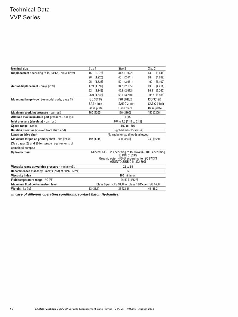
Technical DataVVP Series
Nominal size Size 1 Size 2 Size 3Displacement according to ISO 3662 - cm3/r (in3/r) 16 (0.976) 31.5 (1.922) 63 (3.844)
20 (1.220) 40 (2.441) 80 (4.882)25 (1.526) 50 (3.051) 100 (6.102)
Actual displacement - cm3/r (in3/r) 17.9 (1.092) 34.5 (2.105) 69 (4.211)22.1 (1.349) 42.8 (2.612) 86.2 (5.260)26.9 (1.642) 53.1 (3.240) 105.5 (6.438)
Mounting flange type (See model code, page 15.) ISO 3019/2 ISO 3019/2 ISO 3019/2SAE 4-bolt SAE C 2-bolt SAE C 2-boltBase plate Base plate Base plate
Maximum working pressure - bar (psi) 160 (2300) 160 (2300) 150 (2200)Allowed maximum drain port pressure - bar (psi) 1 (15)Inlet pressure (absolute) - bar (psi) 0.8 to 1.5 [11.6 to 21.8]Speed range - r/min 800 to 1800Rotation direction (viewed from shaft end) Right-hand (clockwise) Loads on drive shaft No radial or axial loads allowedMaximum torque on primary shaft - Nm (lbf-in) 197 (1744) 400 (3540) 740 (6550)(See pages 28 and 30 for torque requirements ofcombined pumps.)Hydraulic fluid
Viscosity range at working pressure - mm2/s (cSt) 22 to 68Recommended viscosity - mm2/s (cSt) at 50°C (122°F) 32Viscosity index 100 minimumFluid temperature range - °C (°F) -10/+50 [14/122]Maximum fluid contamination level Class 9 per NAS 1638, or class 18/15 per ISO 4406Weight - kg (lb) 13 (28.7) 33 (72.8) 45 (99.2)
In case of different operating conditions, contact Eaton Hydraulics.
Mineral oil - HM according to ISO 6743/4 - HLP accordingto DIN 51524/2
Organic ester HFD-U according to ISO 6743/4(QUINTOLUBRIC N-822-300)

EATON Vickers VVS/VVP Variable Displacement Vane Pumps V-PUVN-TM002-E August 2004
Controls forVVP Pumps
VVP pumps offer a wide selec-tion of electrohydraulic controlsfor the regulation of pressureand volume.
In addition to the various pres-sure regulating controls, ahydraulic load-sensing control isavailable to provide pumps withmaximum flexibility for use inenergy saving systems.
The load sensing compensatorcontrol receives a signal pres-sure directly after an externalthrottle and before an actuator.When a variation in pressure issensed (with a fixed fall in pres-sure ∆p = 20 bar (300 psi), thecontrol will automaticallychange the pump’s displace-ment independent of pressurevariations that occur in the circuit.
The load sensing control pro-duces a notable reduction indisplaced power and is recom-mended for use in applicationswhere there are notable varia-tions in torque (or force) andspeed.
Q
P
Q
P
Remote max. pressure relief valve from 0 to 5 L/min (0 to 1.3 USgpm) not supplied.Length of pilot line between compensator and relief valve should not exceed 5m (16 ft).
Q
P
Q
P
Q
P
17
Pressure RegulationPump With StandardPressure CompensatorModel Code “C”
Pump WithRemote Pressure ControlModel Code “CR”
Pump With Two Stages ofPressure of Which One WithFixed Setting (At MinimumPressure Level of Pump)Model Code “CD1”

EATON Vickers VVS/VVP Variable Displacement Vane Pumps V-PUVN-TM002-E August 200418
Controls forVVP Pumps(continued)
Q
P
Standard loadsense device
Manual orelectroproportional throttle(not supplied)
Max. pressure relief valve from 0 to 5 L/min (0 to 1.3 USgpm) not supplied.Length of pilot line between compensator and relief valve should not exceed 5m (16 ft).
Double pressureload sensedevice
Manual orelectroproportional throttle(not supplied)
Q
P
Load Sensing andPressure Regulation
Load Sensing Pump forStandard Flow ControlModel Code “CVP”
Q
P
Q
P
Pump With Two AdjustableStages of Pressure Model Code “CD2”
Pump With Proportional Pressure ControlModel Code “CE”
Load Sensing Pump WithRemote Pressure ControlModel Code “CVPR”

19EATON Vickers VVS/VVP Variable Displacement Vane Pumps V-PUVN-TM002-E August 2004
Controls forVVP Pumps(continued)
Double pressureload sensedevice
Manual orelectroproportionalthrottle (not supplied)
Q
P
Q
P
Manual orelectroproportionalthrottle (not supplied)
Double pressureload sensedevice
Q
P
Manual orelectroproportionalthrottle (not supplied)
Double pressureload sensedevice
Load Sensing Pump WithTwo Stages of Pressure ofWhich One With FixedSetting (At Min. PressureLevel of Pump)Model Code “CVPD1”
Load Sensing Pump WithTwo Adjustable Stages ofPressureModel Code “CVPD2”
Load Sensing Pump WithProportional Pressure ControlModel Code “CVPCE”
PressureRegulation withTorque Sensing
Torque LimiterModel Code “CVT”
P
Q

EATON Vickers VVS/VVP Variable Displacement Vane Pumps V-PUVN-TM002-E August 200420
Controls forVVP Pumps(continued)
Remote Controlled TorqueLimiterModel Code “CVTR”
P
Q
Remote max. pressure relief valve from 0 to 5 L/min (0 to 1.3 USgpm)not supplied. Length of pilot line between compensator and relief valveshould not exceed 5m (16 ft).
Torque Control With DualPressure ControlModel Code “CVTD”(Fixed Minimum Pressure)
P
Q
Torque Control WithProportional Pressure ControlModel Code “CVTCE”
P
QManual orelectroproportionalthrottle (not supplied)
Double pressureload sensedevice

EATON Vickers VVS/VVP Variable Displacement Vane Pumps V-PUVN-TM002-E August 2004 21
PerformanceCharacteristicsVVP1
Performance with:
Speed 1450 r/min
Oil per ISO 6743/4
Viscosity 32 mm2/s (cSt)
Temperature 50°C (122°F)
80(1200)
Operating pressure - bar (psi)
10 (2.64)
40 (10.57)
20 (5.28)
30 (7.93)
0 100(1500)
20(300)
40(600)
60(900)
120(1750)
140(2000)
160(2300)
4 (5.36)2 (2.68)
8 (10.73)
6 (8.05)
12 (16.09)10 (13.41)
Inpu
t pow
er -
kW (h
p)
Flow
- L/
min
(USg
pm)
80(1200)
60(900)
Inpu
t pow
er -
kW (h
p)
35 (9.25)
10 (2.64)
15 (3.96)
20 (5.28)
25 (6.60)
30 (7.93)
0
Operating pressure - bar (psi)
40(600)
20(300)
120(1750)
100(1500)
160(2300)
140(2000)
Flow
- L/
min
(USg
pm)
4 (5.36)
2 (2.68)
8 (10.73)6 (8.05)
12 (16.09)10 (13.41)
80(1200)
60(900)
40(600)
20(300)
0
5 (1.32)
10 (2.64)
15 (3.96)
20 (5.28)
25 (6.60)
30 (7.93)
Inpu
t pow
er -
kW (h
p)
Flow
- L/
min
(USg
pm)
120(1750)
100(1500)
160(2300)
140(2000)
4 (5.36)
2 (2.68)
6 (8.05)
8 (10.73)
Operating pressure - bar (psi)
0
16-20-25
50 ms
pres
sure
(bar
) [p
si]
40 [580]
100 [1450]
160 [2321]
220 [3191]
280 [4061]
time ms
64
62
dB(A
)
68
66
70
16-20-2574
72
16014012060 804020 100
pressure bar (psi) (2031)(1740) (2321)(1160)(580)(290) (870) (1450)
0
16-20-25
drai
nage
l/m
in (
USg
pm)
2 (0.53)
1 (0.26)
3 (0.79)
5 (1.32)
4 (1.06)
pressure bar (psi)
160(2031)140
(1740)120
(2321)60
(1160)8040
(580)(290)20
(870) (1450)100
VVP1-16
VVP1-20
VVP1-25
VVP1-16, -20, -25Values established with zero flow setting
VVP1-16, -20, -25Maximum noise level measured with sound-level meter placed at1 meter [39.37”] from pump, flexible coupling.
VVP1-16, -20, -25Response time and pressure peak
Power consumption withmaximum flow
Power consumption with zeroflow setting
EATON Vickers VVS/VVP Variable Displacement Vane Pumps V-PUVN-TM002-E August 200422
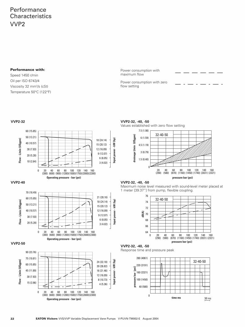
PerformanceCharacteristicsVVP2
Performance with:
Speed 1450 r/min
Oil per ISO 6743/4
Viscosity 32 mm2/s (cSt)
Temperature 50°C (122°F)
120(1750)
15 (3.96)
60 (15.85)
45 (11.89)
30 (7.93)
0 100(1500)
20(300)
40(600)
60(900)
80(1200)
140(2000)
160(2300)
4 (5.36)8 (10.73)
12 (16.09)
16 (21.46)
Inpu
t pow
er -
kW (h
p)
75 (19.81)
90 (23.76)
20 (26.82)24 (32.18)
Operating pressure - bar (psi)
Flow
- L/
min
(USg
pm)
120(1750)
140(2000)
3 (4.02)6 (8.05)
12 (16.09)15 (20.12)
9 (12.07)
18 (24.14)21 (28.16)
0 100(1500)
20(300)
40(600)
60(900)
80(1200)
160(2300)
20 (5.28)
30 (7.93)
40 (10.57)
50 (13.21)
60 (15.85)
70 (18.49)
Inpu
t pow
er -
kW (h
p)
Operating pressure - bar (psi)
Flow
- L/
min
(USg
pm)
120(1750)
100(1500)
20(300)
40(600)
60(900)
80(1200)
0
10 (2.64)
20 (5.28)
30 (7.93)
140(2000)
160(2300)
Inpu
t pow
er -
kW (h
p)
Operating pressure - bar (psi)
40 (10.57)
50 (13.21)
60 (15.85)
3 (4.02)
6 (8.05)
12 (16.09)
15 (20.12)
9 (12.07)
18 (24.14)
Flow
- L/
min
(USg
pm)
0
32-40-50
50 ms
220 (3191)
280 (4061)
40 (580)
100 (1450)
160 (2321)
pres
sure
bar
(ps
i)
time ms
32-40-50
66
640
dB(A
)
70
68
72
76
74
120(1740)
pressure bar (psi)(290)20
(580)40 60
(870)100
(1450)(1160)80
(2321)140
(2031)160
32-40-50
0
7.5 (1.98)
6 (1.59)
3 (0.79)
1.5 (0.40)
4.5 (1.19)
drai
nage
l/m
in (
USg
pm)
(1160)
pressure bar (psi)
(580)40
(290)20
(870)60 80
(2031)140
(1450)100
(1740)120
(2321)160
VVP2-32
VVP2-40
VVP2-50
VVP2-32, -40, -50Values established with zero flow setting
VVP2-32, -40, -50Maximum noise level measured with sound-level meter placed at1 meter [39.37”] from pump, flexible coupling.
VVP2-32, -40, -50Response time and pressure peak
Power consumption withmaximum flow
Power consumption with zeroflow setting
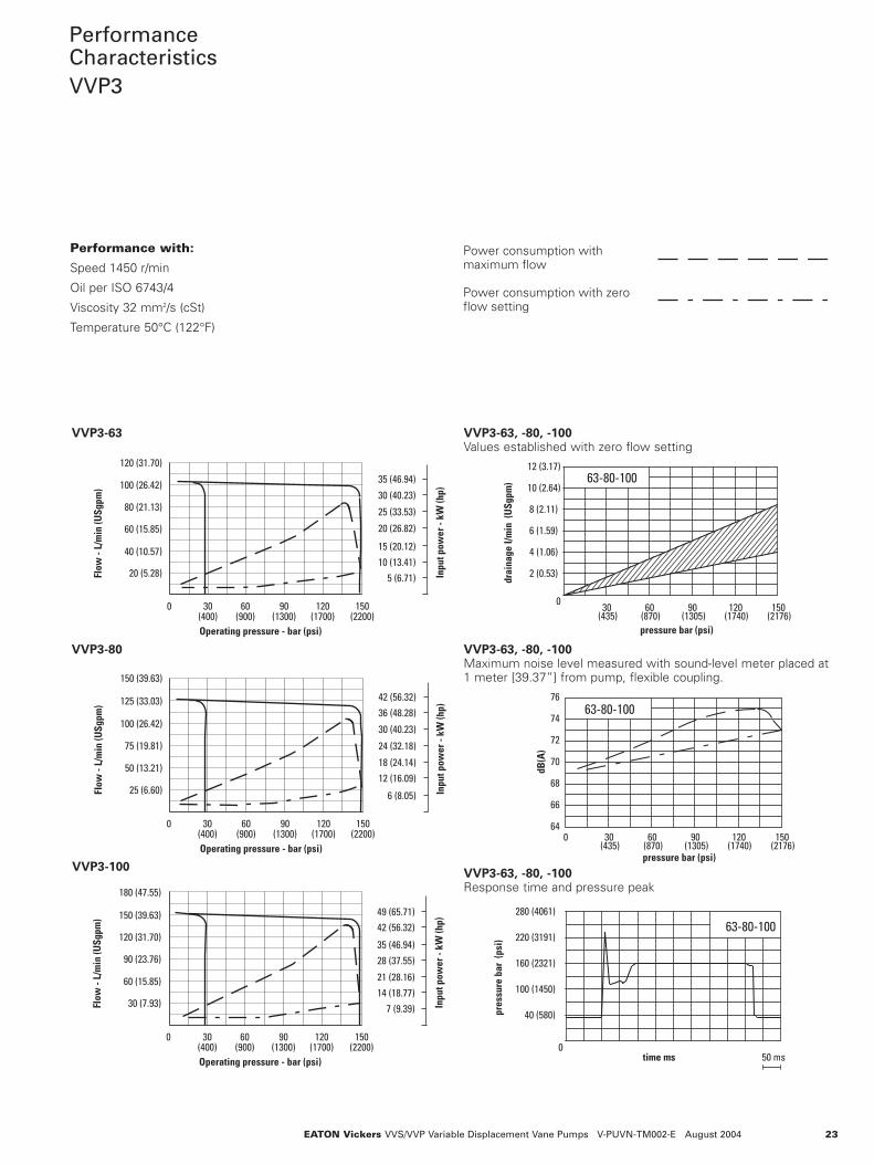
PerformanceCharacteristicsVVP3
Performance with:
Speed 1450 r/min
Oil per ISO 6743/4
Viscosity 32 mm2/s (cSt)
Temperature 50°C (122°F)
60 (15.85)
30 (7.93)
0
90 (23.76)
120 (31.70)
150 (39.63)
180 (47.55)
30(400)
60(900)
90(1300)
150(2200)
120(1700)
7 (9.39)14 (18.77)21 (28.16)
28 (37.55)35 (46.94)
42 (56.32)49 (65.71)
Inpu
t pow
er -
kW (h
p)
Operating pressure - bar (psi)
Flow
- L/
min
(USg
pm)
30 (40.23)
12 (16.09)18 (24.14)
6 (8.05)
24 (32.18)
36 (48.28)42 (56.32)
0
25 (6.60)
50 (13.21)
75 (19.81)
30(400)
60(900)
90(1300)
150(2200)
120(1700)
100 (26.42)
125 (33.03)
150 (39.63)
Operating pressure - bar (psi)
Flow
- L/
min
(USg
pm)
Inpu
t pow
er -
kW (h
p)
30(400)
60(900)
90(1300)
150(2200)
0
20 (5.28)
40 (10.57)
60 (15.85)
5 (6.71)10 (13.41)
20 (26.82)
25 (33.53)
15 (20.12)
30 (40.23)
120(1700)
100 (26.42)
120 (31.70)
35 (46.94)
80 (21.13)
Flow
- L/
min
(USg
pm)
Operating pressure - bar (psi)
Inpu
t pow
er -
kW (h
p)
0
63-80-100
50 ms
220 (3191)
280 (4061)
40 (580)
100 (1450)
160 (2321)
pres
sure
bar
(ps
i)
time ms
63-80-100
66
640
dB(A
)
70
68
72
76
74
pressure bar (psi)(435)30
(870)60 90
(1305) (2176)120
(1740)150
63-80-100
0
pressure bar (psi)(435)30
(870)60
(1305)90
(2176)(1740)120 150
10 (2.64)
drai
nage
l/m
in (
USg
pm)
2 (0.53)
4 (1.06)
6 (1.59)
8 (2.11)
12 (3.17)
VVP3-63
VVP3-80
VVP3-100
VVP3-63, -80, -100Values established with zero flow setting
VVP3-63, -80, -100Maximum noise level measured with sound-level meter placed at1 meter [39.37”] from pump, flexible coupling.
VVP3-63, -80, -100Response time and pressure peak
Power consumption withmaximum flow
Power consumption with zeroflow setting
EATON Vickers VVS/VVP Variable Displacement Vane Pumps V-PUVN-TM002-E August 2004 23

EATON Vickers VVS/VVP Variable Displacement Vane Pumps V-PUVN-TM002-E August 200424
VVP1With ISO or SAEMounting FlangeInstallation Dimensionsin mm (in)
All mounting flange, port andshaft options are listed onpage 36.
3rd angleprojection
Identificationplate
Outlet port“D” thread
26 (1.02)
W
Pressure setting knob. Turningclockwise increases pressure.
140 (5.51)
19 (0.79)
32.5 (1.28)
7 x 7 (0.28 x 0.28) adjuster of maximumdisplacement stop; suitable for handwheel.(Optional feature - see model code)
T
26.6 (1.05)16.3 (0.64)
6 (0.24)
31 (1.22) 40.5 (1.59)P
10 (0.39)
28(1.102)
66(2.60)
66(2.60)
Ø CC
80 (3.15) 9 (0.35)
26 (1.02)
Ø BB
Ø AAInlet port. “DD” thd.
JJ
82 (3.23)
70 (2.75)
Case drain “J” thread Ø V
N
ISO 4401, size 3(NFPA D03)controlmounted here
120(4.72)
120 (4.72)
118.5(4.67)
X
200.5(7.89)
82(3.23)
96(3.78)
159 (6.25)GG
70(2.75)
“C” ControlWith “K” Adjustment
“KL” adjustment is shown onpage 35.
MOUNTING FLANGEAND PORTS CODE � D F J N Ø V W Ø AA Ø BB Ø CC DD GG JJ
R (ISO) 3/4” BSP 1/4” BSP 3/8” BSP 8 125 28 25 100 11.0 1” BSP 205 46(0.315) (4.921) (1.102) (0.984) (3.937) (0.433) (8.07) (1.81)
PS (SAE) 1.0625-12 0.500-20 0.5625-18 6.35 127 28.17 25.4 101.6 14.3 1.3125-12 207 48UNF-2B UNF-2B UNF-2B (0.250) (5.000) (1.109) (1.000) (4.000) (0.56) UNF-2B (8.15) (1.89)
� See model code, page 15.
VVP CONTROL CR CD1 CD2 CE CVP CVPR CVPD1 CVPD2 CVPCE CVT(*)
Dimension “X” 20.0 100.0 � 146.0 � 125.5 � 20.0 40.0 120.0 � 166.0 � 145.5 � 115.0(0.79) (3.94) � (5.75) � (4.94) � (0.79) (1.57) (4.72) � (6.54) � (5.73) � (4.55)
� Includes 13 (0.51) for removal of DIN connector.
Thread for remote control connection, type CR = dimension “F”.Thread for load sense connection, type CV* = dimension “F”.

25EATON Vickers VVS/VVP Variable Displacement Vane Pumps V-PUVN-TM002-E August 2004
VVP2 and VVP3With ISOMounting FlangeInstallation Dimensionsin mm (in)
All mounting flange, port andshaft options are listed onpage 36.
3rd angleprojection
Outlet port Ø D
140 (5.51) max.
“E” thread4 places
W
Identification plate
BC
A
EE
T
19(0.79)
32.5 (1.28)26.6 (1.05)16.3 (0.64)6 (0.24)
31 (1.22) 40.5 (1.59)
P
X Inlet portØ DD
N
Ø V
K
67 (2.64)
Ø M
10 x 10 (0.39 x 0.39)adjuster of maximumdisplacement stop.Optional feature -see model code.
Y
10 (0.39)
45 (1.77)
Case drain“J” thread
9 (0.35)
ISO 4401, size 3(NFPA D03)controlmounted here
“P” thread4 places
X
H
MM R
K
NN
EEJJ
AA
RU
BB
GGFF
T
Z
“C” ControlWith “K” Adjustment
“KL” adjustment is shown onpage 35.
MODEL A B C D E H J K Ø M N P R T
VVP2 52.4 26.2 30 25 M10 or 110 3/4” BSP or 95 14 10 M12 or 150 123(2.06) (1.03) (1.18) (0.98) 0.375-16 (4.33) 1.0625-12 (3.74) (0.55) (0.39) 0.500-13 (5.91) (4.84)
UNC-2B � UNF-2B � UNC-2B �VVP3 58.7 30.2 35 32 M10 or 120 3/4” BSP or 105 18 12 M12 or 185 133
(2.31) (1.19) (1.378) (1.26) 0.4375-14 (4.72) 1.0625-12 (4.13) (0.71) (0.47) 0.500-13 (7.28) (5.24)UNC-2B � UNF-2B � UNC-2B �
� See mounting flange/port connections codes RF and PX, page 15.
Thread for remote control or load sense connection, type CR orCV* = 1/4” BSP.
MODEL U Ø V W X Y Z Ø AA Ø BB Ø DD EE FF GG JJ MM NN
VVP2 114 160 35 35.7 40 70 32 125 38 91 219 279 60 255.5 145.5(4.49) (6.30) (1.38) (1.41) (1.58) (2.76) (1.26) (4.92) (1.50) (3.58) (8.62) (10.98) (2.36) (10.06) (5.728)
VVP3 123 200 43 43 46 77.8 40 160 51 105 245 313 68 275.5 155.5(4.84) (7.87) (1.69) (1.69) (1.81) (3.06) (1.57) (6.30) (2.01) (4.13) (9.65) (12.32) (2.68) (10.85) (6.12)
VVP CONTROL CR CD1 CD2 CE CVP CVPR CVPD1 CVPD2 CVPCE CVT(*)
Dimension “X” 20.0 100.0 � 146.0 � 125.5� 20.0 40.0 120.0 � 166.0 � 145.5 � 115.0(0.79) (3.94) � (5.75) � (4.94) � (0.79) (1.57) (4.72) � (6.54) � (5.73) � (4.55)
� Includes 13 (0.51) for removal of DIN connector.

EATON Vickers VVS/VVP Variable Displacement Vane Pumps V-PUVN-TM002-E August 200426
VVP2 and VVP3With SAEMounting FlangeInstallation Dimensionsin mm (in)
All mounting flange, port andshaft options are listed onpage 36.
3rd angleprojection
18(0.71)
67(2.64)
K
Identification plate
Outlet portØ D
34.5(1.36)
E thread4 places
45 (1.77)10 x 10 (0.39 x 0.39)adjuster of maximumdisplacement stop.Optional feature -see model code.
Ø 31.75(1.25)
Key 6,35 (0.25) wide
58 (2.28) EE
10 (0.39)
Inlet portØ DD
0.500-13 UNC-2Bthd. 4 places
Z
Y
X
9 (0.35)
Case drain1.0625-12 UNF-2Bthread
T
19 (0.79)
32.5 (1.28)26.6 (1.05)16.3 (0.64)6 (0.24)
31 (1.22) 40.5 (1.59)
PISO 4401, size 3(NFPA D03)controlmounted here
BC
EE
X
140(5.51) max.
GGFF
T
Ø 127(5.00)181
(7.13)
210(8.27)
K
U
NN
MM
H
A
“C” ControlWith “K” Adjustment
“KL” adjustment is shown onpage 35.
Thread for remote control or load sense connection, type CR orCV* = 0.500-20 UNF-2B
MODEL A B C D E H K T U
VVP2 52.4 26.2 27 25 0.375-16 110 95 123 114(2.06) (1.03) (1.06) (0.98) UNC-2B (4.33) (3.74) (4.84) (4.49)
VVP3 58.7 30.2 35 32 0.4375-14 120 105 133 123(2.31) (1.19) (1.38) (1.26) UNC-2B (4.72) (4.13) (5.24) (4.84)
MODEL X Y Z Ø DD EE FF GG MM NN
VVP2 35.7 40 70 38 91 219 279 256 145.5(1.41) (1.58) (2.76) (1.50) (3.58) (8.62) (10.98) (10.08) (5.73)
VVP3 43 46 77.8 51 105 245 303 275.5 155.5(1.69) (1.81) (3.06) (2.00) (4.13) (9.65) (11.93) (10.85) (6.12)
VVP CONTROL CR CD1 CD2 CE CVP CVPR CVPD1 CVPD2 CVPCE CVT(*)
Dimension “X” 20.0 100.0 � 146.0 � 125.5 � 20.0 40.0 120.0 � 166.0 � 145.5 � 115.0(0.79) (3.94) � (5.75) � (4.94) � (0.79) (1.57) (4.72) � (6.54) � (5.73) � (4.55)
� Includes 13 (0.51) for removal of DIN connector.

27EATON Vickers VVS/VVP Variable Displacement Vane Pumps V-PUVN-TM002-E August 2004
VVS and VVPBased Mounted Installation Dimensionsin mm (in)
3rd angleprojection
25 (0.98)max.
Ø AA
Ø DD inlet port
H
2.2 (0.09)
Ø D outlet port
Ø J drain port (VVS2 and VVP2 only)
Ø CC
X
N
W
A
Pressure adjustment knob (VVP)Turning clockwise increases pressure.
Identification plate
Flow adjustment screw (upon request).Turning clockwise decreases flow.
Pressure settingscrew (VVS).Turning clockwiseincreases pressure.
Ø J drain port (VVS1,VVP1, VVS3 andVVP3 only)
Ø PK Z L
T
Ø MØ M
B
F
R
UV
S
G
CE (VVP)
BBGG
140 (5.51)max. (VVP)
R
Y max.
MODEL A B C Ø D E F G H Ø J K L Ø M N Ø P
VVS1 25 82 131 14 118.5 80 54 13 6 32 52.5 32.5 5 14VVP1 (0.98) (3.23) (5.16) (0.55) (4.67) (3.15) (2.13) (0.51) (0.24) (1.26) (2.07) (1.28) (0.20) (0.55)VVS2 31 110 175 24 145.5 113 75 20 10 50 68 45.5 10 20.5VVP2 (1.22) (4.33) (6.89) (0.94) (5.73) (4.45) (2.95) (0.79) (0.39) (1.97) (2.68) (1.79) (0.39) (0.81)VVS3 53.5 120 185 28 155.5 123 114 21 13 47 57.5 48 6.35 28VVP3 (2.11) (4.72) (7.28) (1.10) (6.12) (4.84) (4.49) (0.83) (0.51) (1.85) (2.26) (1.89) (0.25) (1.10)
MODEL R S T U V W X Y Z AA BB Ø CC Ø DD GG
VVS1 25.5 46 25.5 121 140 21 - 30 27 19 89.5 11 21 201VVP1 (1.00) (1.81) (1.00) (4.76) (5.51) (0.83) (1.18) (1.06) (0.75) (3.52) (0.43) (0.83) (7.91)VVS2 38 57 30 159 190 35 12.5 40 33 32 129 11 32 280VVP2 (1.50) (2.24) (1.18) (6.26) (7.48) (1.38) (0.49) (1.57) (1.30) (1.26) (5.08) (0.43) (1.26) (11.02)VVS3 57 76 51 247.5 273 27.5 - 40 55.5 25.37 140 13 35 300VVP3 (2.24) (2.99) (2.01) (9.74) (10.75) (1.08) (1.57) (2.19) (1.00) (5.51) (0.51) (1.38) (11.81)

EATON Vickers VVS/VVP Variable Displacement Vane Pumps V-PUVN-TM002-E August 200428
CombinedPumps
The rotor shaft of Vickers(™)variable vane pumps is pre-arranged for mounting an addi-tional pump. Simply take offthe rear cover to easily attachthe secondary pump. (Seeitems A and B on sectionalview, page 4.)
Vickers(™) combined standardpumps (see table below) elimi-nate the need for many “spe-cial application” pumps.
For solutions other than thoseshown in the table, contactyour Eaton representative.
Check valves required(not supplied) if flows
are combined
Combined pumps
Typical PumpCombinations
Components forCombining Pumps
Ordering CombinedPumps
MAX. TORQUE ONPRIMARY SECONDARY ADAPTER DRIVE SHAFT FORPUMP PUMP KIT PART NO. SECONDARY PUMP
VV*1-***-R/PS VVS0-R AK-VVS/VVP1-0-R 02-358847 55 Nm (487 lbf-in)VVS0-PS AK-VVS/VVP1-0-PS 02-358848VV*1-R AK-VVS/VVP1-1-R 02-358849VV*1-PS AK-VVS/VVP1-1-PS 02-358850SAE A 2-bolt � AK-VVS/VVP1-SAE-A 02-358851
VV*2/3-RF/PF VVS0-R AK-VVS/VVP2/3-0-R � 02-358852 110 Nm (974 lbf-in)VVS0-PS AK-VVS/VVP2/3-0-PS � 02-358853VV*1-R AK-VVS/VVP2/3-1-R � 02-358717VV*1-PS AK-VVS/VVP2/3-1-PS � 02-358854VV*2-RF/PX AK-VVS/VVP2/3-2-RF/PX � 02-358855SAE A 2-bolt � AK-VVS/VVP2/3-SAE-A � 02-358856SAE B 2-bolt � AK-VVS/VVP2/3-SAE-B � 02-358857
VV*3-RF/PF VV*3-RF/PX AK-VVS/VVP3-3-RF/PX 02-358858 180 Nm (1593 lbf-in)
� SAE A and B 2-bolt are generic interfaces. Secondary pump with SAE A or B mount should conform to dimensions onthe following page.
� Adapter kits for same displacements within frame sizes 2 and 3 primary pumps are identical.
Order pumps and coupling unit in progressive order of coupling.Example:
One (1) VVP1-20-RR-M-30-CVTCE03B-15-10 Primary Pump
One (1) AK-VVS/VVP1-0-R Adapter Kit
One (1) VVS0-10-RR-M-40-CCW-10 Secondary Pump

29EATON Vickers VVS/VVP Variable Displacement Vane Pumps V-PUVN-TM002-E August 2004
CombinedPumps(continued)
Secondary pumps with SAEA or B 2-bolt mounts shouldconform to the dimensionsbelow. Dimensions in mil-limeters (inches). D
F
C
E
Ø BØ A
2-BOLT FLANGEPRIMARY OF SECONDARYPUMP PUMP � ADAPTER KIT Ø A Ø B C D E MAX. F
VVS1 SAE A AK-VVS/VVP1-SAE-A 82.5 19.05 21.1 4.8 50 7VVP1 (3.25) (0.75) (0.83) (0.19) (1.97) (0.28)VVS2 SAE A AK-VVS/VVP2/3-SAE-A 82.5 19.05 21.1 4.8 60 7VVP2 (3.25) (0.75) (0.83) (0.19) (2.36) (0.28)VVS3 SAE B AK-VVS/VVP2/3-SAE-B 101.6 22.2 25.1 6.375 9.5VVP3 (4.00) (0.87) (0.99) � (0.25) � (0.37)
25.5 4.8(1.00) � (0.19) �
� Secondary pumps with ISO mounting flange are listed on page 28.� Both shafts are accommodated within same coupling.

EATON Vickers VVS/VVP Variable Displacement Vane Pumps V-PUVN-TM002-E August2004
30
TorqueRequirementsCombinedPumps
Pump Frame Size 2
Drive shaft ofprimary pump
Drive shaft forsecondary pump
Combined pumps must beinstalled in decreasing order ofdisplacement. Torque require-ments and limitations of singleand combined pumps must notexceed the values shown in thetables below.
Pump Frame Size 1
Pump Frame Size 3
MAXIMUM TORQUE ONREQUIRED TORQUE DRIVE SHAFT FORFOR PRIMARY PUMP SECONDARY PUMP
PUMP TYPE Nm (lbf-in) Nm (lbf-in)
VVS1-16 30 (266)VVS1-20 37 (327)VVS1-25 46 (407)VVP1-16 47 (416)VVP1-20 58 (513)VVP1-25 73 (646)
MAXIMUM TORQUE ONREQUIRED TORQUE DRIVE SHAFT FORFOR PRIMARY PUMP SECONDARY PUMP
PUMP TYPE Nm (lbf-in) Nm (lbf-in)
VVS2-32 57 (504)VVS2-40 73 (646)VVS2-50 91 (805)VVP2-32 92 (814)VVP2-40 117 (1036)VVP2-50 146 (1292)
MAXIMUM TORQUE ONREQUIRED TORQUE DRIVE SHAFT FORFOR PRIMARY PUMP SECONDARY PUMP
PUMP TYPE Nm (lbf-in) Nm (lbf-in)
VVS3-63 92 (814)VVS3-80 117 (1036)VVS3-100 146 (1292)VVP3-63 172 (1522)VVP3-80 219 (1938)VVP3-100 273 (2416)
180 (1593)
110 (974)
55 (487)
31EATON Vickers VVS/VVP Variable Displacement Vane Pumps V-PUVN-TM002-E August 2004
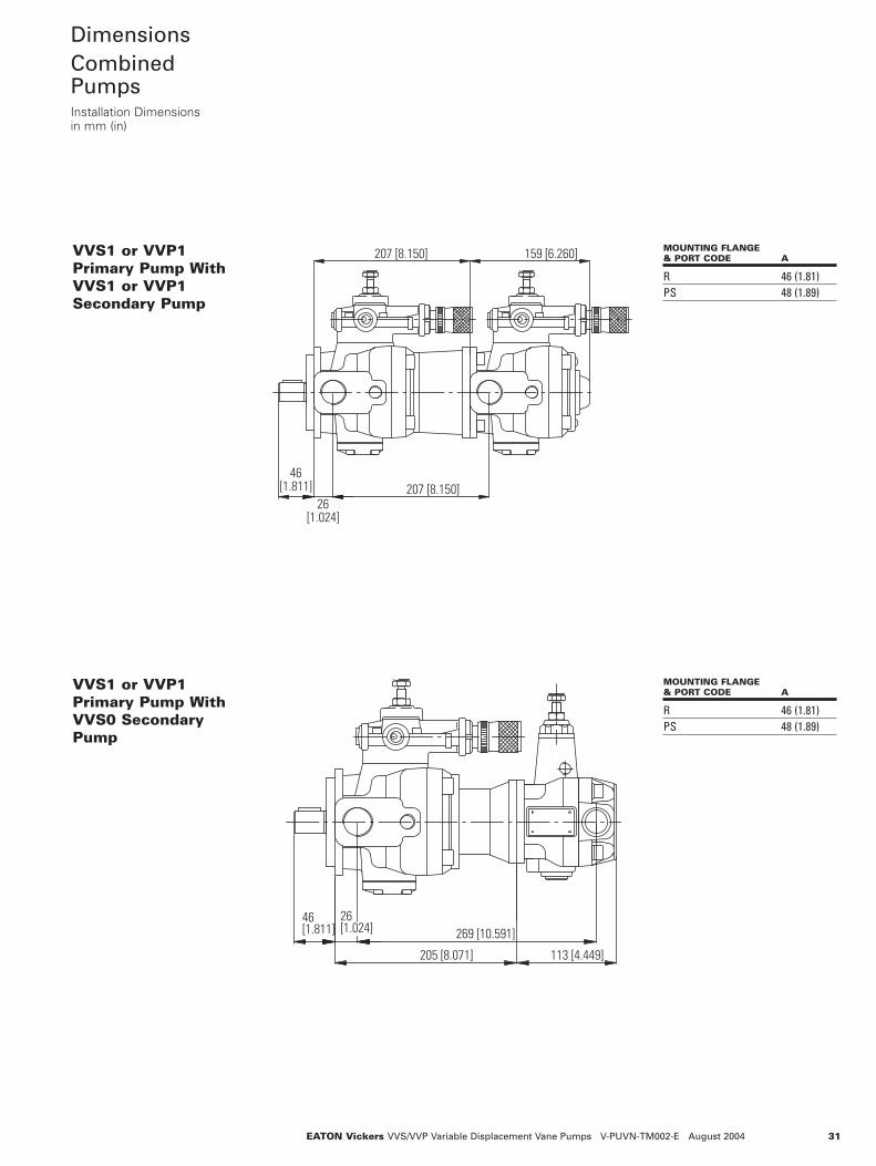
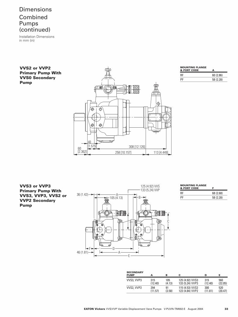
DimensionsCombinedPumpsInstallation Dimensionsin mm (in)
205 [8.071]
46[1.811] 269 [10.591]
113 [4.449]
26[1.024]
46[1.811]
26[1.024]
207 [8.150]
207 [8.150] 159 [6.260]VVS1 or VVP1Primary Pump WithVVS1 or VVP1Secondary Pump
VVS1 or VVP1Primary Pump WithVVS0 SecondaryPump
MOUNTING FLANGE& PORT CODE A
R 46 (1.81)PS 48 (1.89)
MOUNTING FLANGE& PORT CODE A
R 46 (1.81)PS 48 (1.89)

EATON Vickers VVS/VVP Variable Displacement Vane Pumps V-PUVN-TM002-E August 200432
DimensionsCombinedPumps(continued)Installation Dimensionsin mm (in)
56(2.20) 40 (1.57)
30 (1.18)
91 (3.58)
246 (9.69)260 (10.24)
419 (16.50)
A
256 (10.08)
115 (4.53) VVS123 (4.84) VVP
40 (1.57)
91 (3.58) 91 (3.58)
115 (4.53) VVS123 (4.84) VVP 115 (4.53) VVS
123 (4.84) VVP
A
30 (1.18) 275 (10.83)
275 (10.83)275 (10.83)
495 (19.49)
VVS2 or VVP2Primary Pump WithVVS2 or VVP2Secondary Pump
VVS2 or VVP2Primary Pump WithVVS1 or VVP1Secondary Pump
MOUNTING FLANGE& PORT CODE A
RF 60 (2.36)PF 58 (2.28)
MOUNTING FLANGE& PORT CODE A
RF 60 (2.36)PF 58 (2.28)
33EATON Vickers VVS/VVP Variable Displacement Vane Pumps V-PUVN-TM002-E August 2004
DimensionsCombinedPumps(continued)Installation Dimensionsin mm (in)
46 (1.81)
36 (1.42)
125 (4.92) VVS133 (5.24) VVP
BA
DA
E
C
105 (4.13)
F
40[1.575]
60[2.362] 258 [10.157]
308 [12.126]
113 [4.449]
VVS2 or VVP2Primary Pump WithVVS0 SecondaryPump
VVS3 or VVP3Primary Pump WithVVS3, VVP3, VVS2 orVVP2 SecondaryPump
MOUNTING FLANGE& PORT CODE A
RF 60 (2.86)PF 58 (2.28)
MOUNTING FLANGE& PORT CODE F
RF 68 (2.68)PF 58 (2.28)
SECONDARYPUMP A B C D E
VVS3, VVP3 315 105 125 (4.92) VVS3 315 560(12.40) (4.13) 133 (5.24) VVP3 (12.40) (22.05)
VVS2, VVP2 294 91 115 (4.53) VVS2 300 520(11.57) (3.58) 123 (4.84) VVP2 (11.81) (20.47)

EATON Vickers VVS/VVP Variable Displacement Vane Pumps V-PUVN-TM002-E August 200434
DimensionsCombinedPumps(continued)Installation Dimensionsin mm (in)
113 [4.449]68[2.677] 283 [11.142]
338 [13.307]46 [1.811]
35[1.378]
46 (1.81)
36 (1.42)
105 (4.13)
56(2.20)
A
125 (4.92) VVS133 (5.24) VVP
275 (10.83)
265 (10.43)444 (17.48)
285 (11.22)
VVS3 or VVP3Primary Pump WithVVS1 or VVP1Secondary Pump
VVS3 or VVP3Primary Pump WithVVS0 SecondaryPump
MOUNTING FLANGE& PORT CODE A
RF 68 (2.68)PF 58 (2.28)
MOUNTING FLANGE& PORT CODE A
RF 68 (2.68)PF 58 (2.28)

35EATON Vickers VVS/VVP Variable Displacement Vane Pumps V-PUVN-TM002-E August 2004
Key LockAdjustment forVVP PumpsInstallation Dimensionsin mm (in)
3rd angleprojection
82 (3.23)
Pressure settingknob. Turningclockwiseincreases pressure.
166 (6.54) max.
ISO 4401, size 3(NFPA D03)controlmounted here82
(3.23)
Pressure setting knob.Turning clockwiseincreases pressure. C
A max.
B
“KL” Adjustment ForVVP1, VVP2 and VVP3Single Pumps
“KL” Adjustment ForVVP1, VVP2 and VVP3Combined Pumps
Note: Because of length, con-trols on combined pumps aremounted perpendicular to pumpshaft.
PUMP A B C
VVP1 162 162 139 (6.38) (6.38) (5.47)
VVP2 155 189 166(6.10) (7.44) (6.54)
VVP3 155 199 176(6.10) (7.83) (6.93)
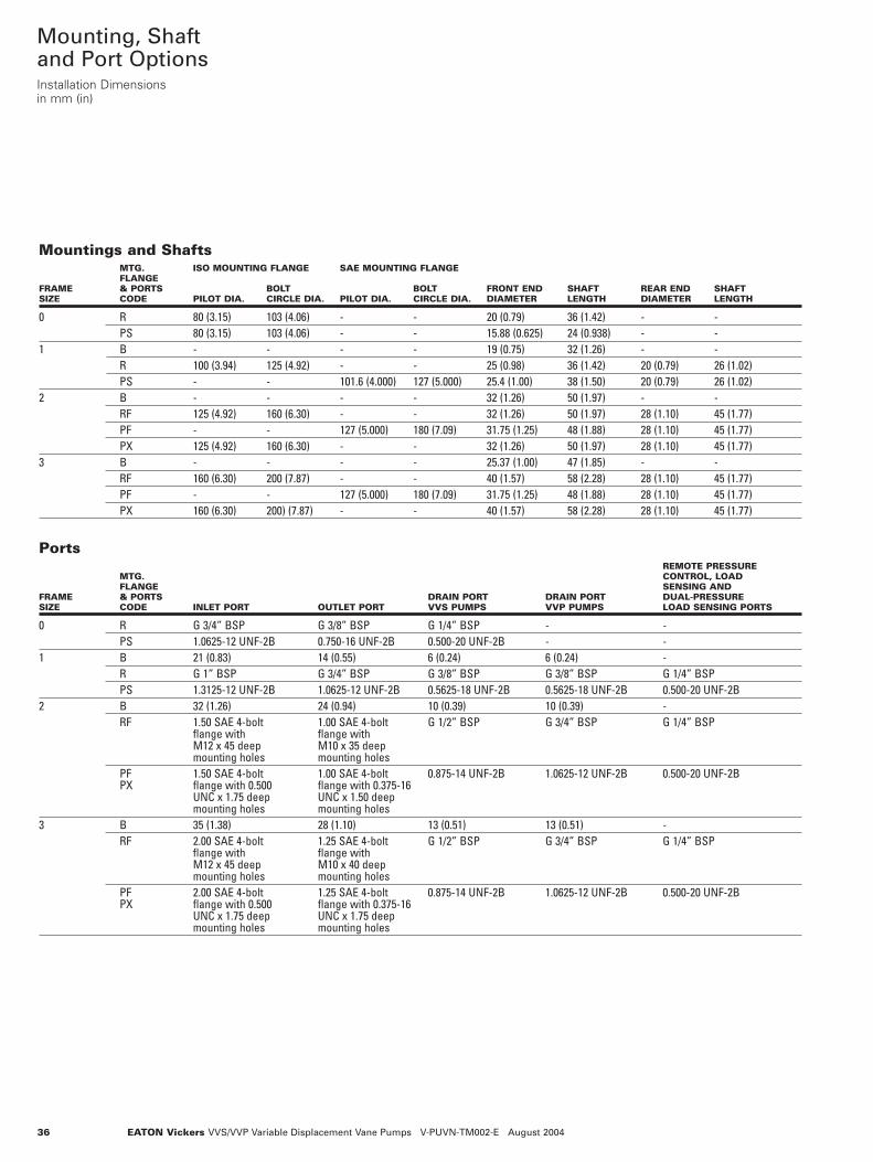
Mountings and ShaftsMTG. ISO MOUNTING FLANGE SAE MOUNTING FLANGEFLANGE
FRAME & PORTS BOLT BOLT FRONT END SHAFT REAR END SHAFTSIZE CODE PILOT DIA. CIRCLE DIA. PILOT DIA. CIRCLE DIA. DIAMETER LENGTH DIAMETER LENGTH
0 R 80 (3.15) 103 (4.06) - - 20 (0.79) 36 (1.42) - -PS 80 (3.15) 103 (4.06) - - 15.88 (0.625) 24 (0.938) - -
1 B - - - - 19 (0.75) 32 (1.26) - -R 100 (3.94) 125 (4.92) - - 25 (0.98) 36 (1.42) 20 (0.79) 26 (1.02)PS - - 101.6 (4.000) 127 (5.000) 25.4 (1.00) 38 (1.50) 20 (0.79) 26 (1.02)
2 B - - - - 32 (1.26) 50 (1.97) - -RF 125 (4.92) 160 (6.30) - - 32 (1.26) 50 (1.97) 28 (1.10) 45 (1.77)PF - - 127 (5.000) 180 (7.09) 31.75 (1.25) 48 (1.88) 28 (1.10) 45 (1.77)PX 125 (4.92) 160 (6.30) - - 32 (1.26) 50 (1.97) 28 (1.10) 45 (1.77)
3 B - - - - 25.37 (1.00) 47 (1.85) - -RF 160 (6.30) 200 (7.87) - - 40 (1.57) 58 (2.28) 28 (1.10) 45 (1.77)PF - - 127 (5.000) 180 (7.09) 31.75 (1.25) 48 (1.88) 28 (1.10) 45 (1.77)PX 160 (6.30) 200) (7.87) - - 40 (1.57) 58 (2.28) 28 (1.10) 45 (1.77)
EATON Vickers VVS/VVP Variable Displacement Vane Pumps V-PUVN-TM002-E August 2004
Mounting, Shaftand Port OptionsInstallation Dimensionsin mm (in)
36
Ports REMOTE PRESSURE
MTG. CONTROL, LOADFLANGE SENSING AND
FRAME & PORTS DRAIN PORT DRAIN PORT DUAL-PRESSURESIZE CODE INLET PORT OUTLET PORT VVS PUMPS VVP PUMPS LOAD SENSING PORTS
0 R G 3/4” BSP G 3/8” BSP G 1/4” BSP - -PS 1.0625-12 UNF-2B 0.750-16 UNF-2B 0.500-20 UNF-2B - -
1 B 21 (0.83) 14 (0.55) 6 (0.24) 6 (0.24) -R G 1” BSP G 3/4” BSP G 3/8” BSP G 3/8” BSP G 1/4” BSPPS 1.3125-12 UNF-2B 1.0625-12 UNF-2B 0.5625-18 UNF-2B 0.5625-18 UNF-2B 0.500-20 UNF-2B
2 B 32 (1.26) 24 (0.94) 10 (0.39) 10 (0.39) -RF 1.50 SAE 4-bolt 1.00 SAE 4-bolt G 1/2” BSP G 3/4” BSP G 1/4” BSP
flange with flange withM12 x 45 deep M10 x 35 deepmounting holes mounting holes
PF 1.50 SAE 4-bolt 1.00 SAE 4-bolt 0.875-14 UNF-2B 1.0625-12 UNF-2B 0.500-20 UNF-2BPX flange with 0.500 flange with 0.375-16
UNC x 1.75 deep UNC x 1.50 deep mounting holes mounting holes
3 B 35 (1.38) 28 (1.10) 13 (0.51) 13 (0.51) -RF 2.00 SAE 4-bolt 1.25 SAE 4-bolt G 1/2” BSP G 3/4” BSP G 1/4” BSP
flange with flange withM12 x 45 deep M10 x 40 deepmounting holes mounting holes
PF 2.00 SAE 4-bolt 1.25 SAE 4-bolt 0.875-14 UNF-2B 1.0625-12 UNF-2B 0.500-20 UNF-2BPX flange with 0.500 flange with 0.375-16
UNC x 1.75 deep UNC x 1.75 deep mounting holes mounting holes

37EATON Vickers VVS/VVP Variable Displacement Vane Pumps V-PUVN-TM002-E August 2004
InstallationInstructions
1) Pump frame sizes 0 and 1can be mounted in any posi-tion. Pump frame sizes 2and 3 must be mountedwith horizontal axis and thecompensator device upward( see figure). When thepump is installed over thetank oil level, it is recom-mended to pay attention tothe inlet pressure. The mini-mum section of the inletpipe must be equal to thesection of the thread inletport of the pump. The inletpipes should be as short aspossible, with a small num-ber of bends and withoutinside section changes.
2) All return and drain pipesmust be placed so that theoil will be not re-suckeddirectly from the pump (seefigure). The oil tank must besuitably sized in order toexchange the thermal powergenerated to the system
components and to have alow re-cycle speed. Toensure maximum pumpworking life, inlet oil temper-ature must never be above50°C (122°F). In the systemswhere the pump runs for along time in zero flow set-ting condition, it is recom-mended to install a heatexchanger in the drain line.The pressure on the drainport must never be inexcess of the specifiedvalue. The drain pipe mustalways be independent ofother return lines, connecteddirectly to the tank andextended sufficiently insidethe tank so as to be belowthe minimum oil level inorder to avoid generatingfoam. Moreover, the drainpipe must be free of restric-tions and as far as possibleaway from the inlet pipe.
3) Motor-pump coupling must
be made with a self-aligningcoupling with convex teethand with cam in polyamidematerial. When assembling,maximum attention must begiven to the distancebetween the two half-cou-plings which must impera-tively fall within the valuespecified in the diagrambelow (detail "A"). Othertypes of motor - pump cou-plings are not permitted. Noinduced RADIAL or AXIALLOADS are allowed on thepump shaft.
4) During the first installation,the pump must be run inmaximum flow condition (Pconnected to T), with the oilflowing directly into the tank,thus to induce air bleeding.For sizes 2 and 3 there is anair bleed placed on the com-pensator device. This phasemust go on for several min-utes. Pump priming (oil out-
put to the delivery side)must occur within a few sec-onds, otherwise the pumpmust be turned off and theoperation repeated.Subsequent start-ups in zeroflow setting conditions areadmissible only with pres-sure not exceeding 30 bar(435 psi), and at conditionthat the system and pumpbe completely filled up withoil. During the starting opera-tions, both the first and thefollowings, the differencebetween the oil temperatureand the environment tem-perature (body pump tem-perature) must not exceedby more than 20°C (68°F).
A A0.05
OUT
IN
DRAIN
45∞
DETAIL A
4 - 7 [0.157 - 0.276]
200
[8] m
in
300 [12] min
50 [2
] min
150 [6] min
100
[4] m
in

© 2004 Eaton CorporationAll Rights ReservedPrinted in USADocument No. V-PUVN-TM002-EAugust 2004
Eaton14615 Lone Oak RoadEden Prairie, MN 55344USATel: 952 937-9800Fax: 952 974-7722www.hydraulics.eaton.com
EatonDr.-Reckeweg-Str. 1D-76532 Baden-BadenGermanyTel: (49) 7221 682-0Fax: (49) 7221 682-788
Eaton20 Rosamond RoadFootscrayVictoria 3011AustraliaTel: (61) 3 9319 8222Fax: (61) 3 9318 5714