Eaton Fuller Automated Transmissions - · PDF fileEaton®Fuller®Automated...
128
For the most current information, visit the Roadranger web site at www.roadranger.com AutoSelect TM AutoShift TM Eaton ® Fuller ® Automated Transmissions Service Manual TRSM-0050 May 2004
Transcript of Eaton Fuller Automated Transmissions - · PDF fileEaton®Fuller®Automated...

For the most current information, visit the Roadranger web site at www.roadranger.com
AutoSelect TM
AutoShift TM
Eaton®Fuller® Automated Transmissions
Service Manual TRSM-0050 May 2004
1
Introduction
Warnings and Cautions
WARNING: Follow the specified procedures in the indicated order to avoid personal injury
CAUTION: Follow the specified procedures in the indicated order to avoid equipment malfunction or damage.
Note: Additional relevant information not covered in the service procedure.
WARNING: Before starting a vehicle:• Sit in the driver's seat• Place shift lever in neutral• Set the parking brake
WARNING: Before working on a vehicle or leaving the cab with engine running:• Place shift lever in neutral• Set the parking brake• Block the wheels
WARNING: When parking the vehicle or leaving the cab:• Place shift lever in neutral• Set the parking brake
CAUTION: Do not release the parking brake or attempt to select a gear until the air pressure is at the correct level.
CAUTION: To avoid damage to the transmission during towing:• Place shift lever in neutral• Lift the drive wheels off of the ground or disconnect the driveline
CAUTION: Do not operate vehicle if alternator lamp is lit or if gauges indicate low voltage.
Every effort has been made to ensure the accuracy of all information in this manual. However, Eaton Truck Component Operations makes no expressed or implied warranty or representation based on the enclosed information. Any errors or omissions may be reported to Marketing Services, Eaton Truck Compo-nent Operations, P.O. Box 4013, Kalamazoo, MI 49003.
Copyright Eaton Corporation, 2001. All rights reserved.
Table of ContentsTable of Contents
IntroductionPurpose ....................................................................... 1Identification Tag ........................................................ 2Model Designations .................................................... 3Lubrication Information .............................................. 4Maintenance/Lubricant Change Intervals .................... 5Preventive Maintenance Overview ............................... 7Repair Warnings ....................................................... 10
Service ProceduresReverse Ball Switch - Overview ................................. 12How to Remove the Reverse Ball Switch ................... 13How to Install the Reverse Ball Switch ...................... 15Rail Select Sensor - Overview ................................... 18How to Remove the Rail Select Sensor ..................... 19How to Install the Rail Select Sensor ........................ 21Gear Select Sensor - Overview .................................. 24How to Remove the Gear Select Sensor .................... 25How to Install the Gear Select Sensor ....................... 27Input/Main Shaft Speed Sensors - Overview ............. 30How to Remove the Input/Main Shaft
Speed Sensors .................................................. 31How to Install the Input/Main Shaft
Speed Sensor ..................................................... 33Output Shaft Speed Sensor - Overview ..................... 36How to Remove the Output Shaft Speed Sensor ....... 37How to Install the Output Shaft Speed Sensor .......... 39Range Valve - Overview ............................................ 42How to Remove the Range Valve .............................. 43How to Install the Range Valve .................................. 45Splitter Valve - Overview ........................................... 48How to Remove the Splitter Valve ............................. 49How to Install the Splitter Valve ................................ 51Air Filter/Regulator - Overview .................................. 54How to Remove the Air Filter/Regulator .................... 55How to Install the Air Filter/Regulator ....................... 57Inertia Brake Solenoid - Overview ............................. 60How to Remove the Inertia Brake Solenoid ............... 61How to Install the Inertia Brake Solenoid .................. 63Inertia Brake - Overview ............................................ 66How to Remove the Inertia Brake .............................. 67How to Install the Inertia Brake ................................. 69Power Module - Overview ......................................... 72How to Remove the Power Module ........................... 73How to Install the Power Module .............................. 75Electric Shifter - Overview ......................................... 78How to Remove the Electric Shifter ........................... 79How to Install the Electric Shifter .............................. 81
Transmission ECU - Overview ...................................84How to Remove the Transmission ECU .....................85How to Install the Transmission ECU .........................87Transmission Harness - Overview .............................90How to Remove the Transmission Harness ...............91How to Install the Transmission Harness ..................93Shift Lever - Overview ...............................................96How to Remove the Shift Lever .................................97How to Install the Shift Lever .....................................99Power Relay - Overview ...........................................102How to Remove the Power Relay .............................103How to Install the Power Relay ................................105System Manager - Overview ....................................108How to Remove the System Manager ......................109How to Install the System Manager .........................111Tower Harness - Overview .......................................114How to Remove the Tower Harness .........................115How to Install the Tower Harness ............................117Gear Display - Overview ...........................................120How to Remove the Gear Display ............................121How to Install the Gear Display ................................123

1
Introduction
Purpose
This manual is designed to provide detailed information necessary to service and repair the Automation of Eaton® Fuller® trans-missions listed on the front.
How to Use This Manual
The service procedures in this manual are for transmission automation components only. To locate the information you need, simply locate the procedure in the table of contents, turn to the page specified, and follow the procedure.
To service the mechanical portion of the transmission system, refer to the model specific transmission service manual.
2
IntroductionIntroduction
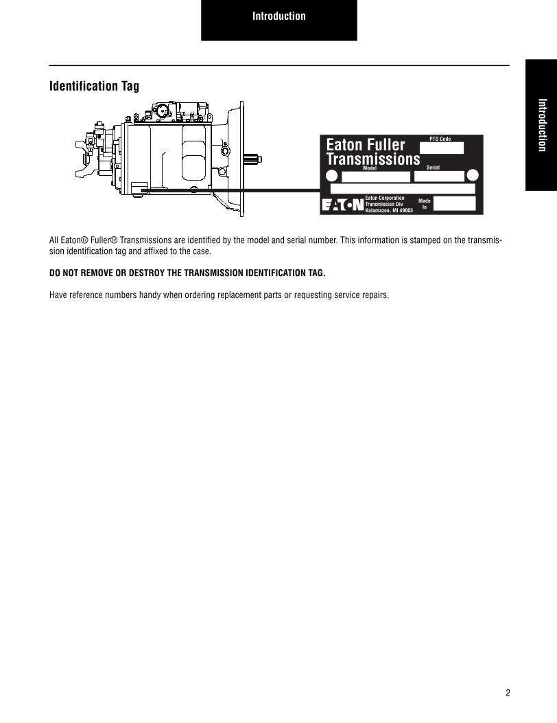
Identification Tag
All Eaton® Fuller® Transmissions are identified by the model and serial number. This information is stamped on the transmis-sion identification tag and affixed to the case.
DO NOT REMOVE OR DESTROY THE TRANSMISSION IDENTIFICATION TAG.
Have reference numbers handy when ordering replacement parts or requesting service repairs.
Eaton FullerTransmissions
PTO Code
Model Serial
MadeIn
Eaton CorporationTransmission DivKalamazoo, MI 49003
3
Introduction
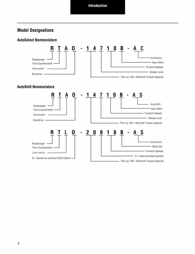
Model Designations
AutoSelect Nomenclature
AutoShift Nomenclature
R T A O - 1 4 7 1 0 B - A C
Roadranger
Twin Countershaft
Automated
Gear Ratio
AutoSelect
Forward Speeds
Design Level
This (x) 100 = Nominal Torque CapacityOverdrive
R T A O - 1 4 7 1 0 B - A S
Roadranger
Twin Countershaft
Automated
Gear Ratio
AutoShift
Forward Speeds
Design Level
This (x) 100 = Nominal Torque CapacityOverdrive
R T L O - 2 0 9 1 8 B - A S
Roadranger
Twin Countershaft
Low-Inertia
Ratio Set
AutoSelect
Forward Speeds
9 = Improved Seal System
This (x) 100 = Nominal Torque CapacityO = Overdrive w/Direct Shift Pattern
4
IntroductionIntroduction
Lubrication Information
Recommended Lubricants
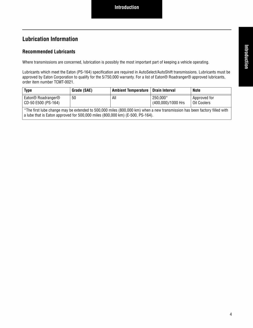
Where transmissions are concerned, lubrication is possibly the most important part of keeping a vehicle operating.
Lubricants which meet the Eaton (PS-164) specification are required in AutoSelect/AutoShift transmissions. Lubricants must be approved by Eaton Corporation to qualify for the 5/750,000 warranty. For a list of Eaton® Roadranger® approved lubricants, order item number TCMT-0021.
Type Grade (SAE) Ambient Temperature Drain Interval Note
Eaton® Roadranger® CD-50 E500 (PS-164)
50 All 250,000* (400,000)/1000 Hrs
Approved for Oil Coolers
*The first lube change may be extended to 500,000 miles (800,000 km) when a new transmission has been factory filled with a lube that is Eaton approved for 500,000 miles (800,000 km) (E-500, PS-164).
Introduction
Maintenance/Lubricant Change Intervals
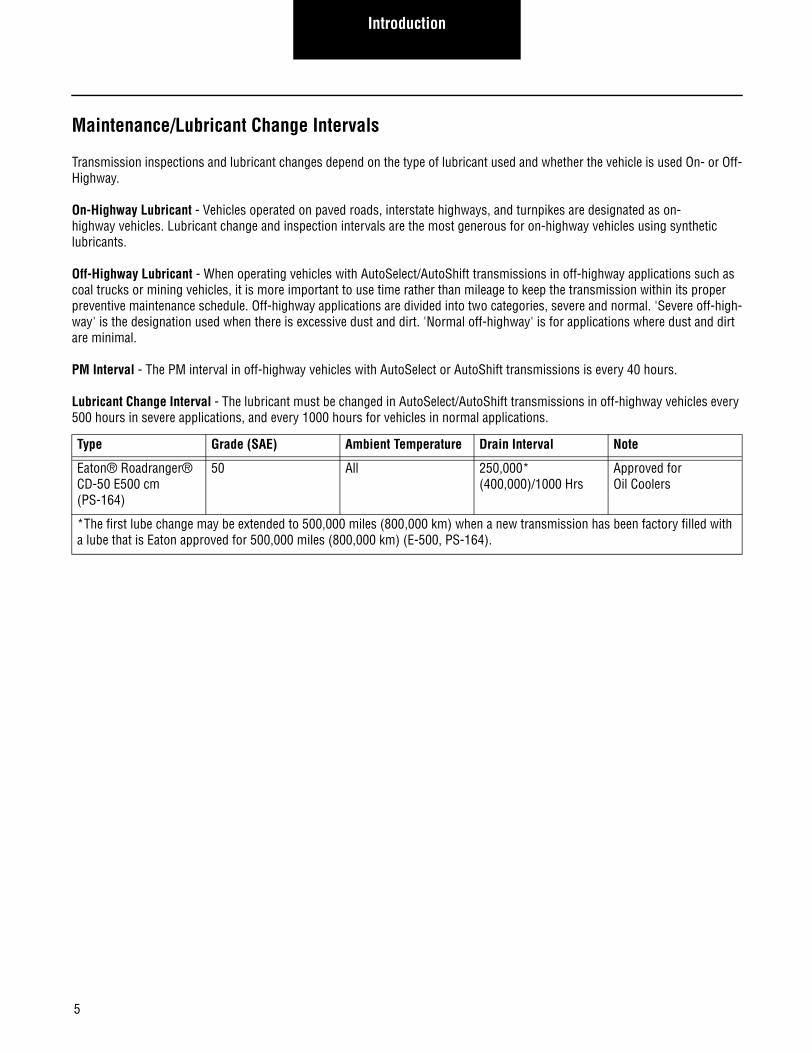
Transmission inspections and lubricant changes depend on the type of lubricant used and whether the vehicle is used On- or Off-Highway.
On-Highway Lubricant - Vehicles operated on paved roads, interstate highways, and turnpikes are designated as on-highway vehicles. Lubricant change and inspection intervals are the most generous for on-highway vehicles using synthetic lubricants.
Off-Highway Lubricant - When operating vehicles with AutoSelect/AutoShift transmissions in off-highway applications such as coal trucks or mining vehicles, it is more important to use time rather than mileage to keep the transmission within its proper preventive maintenance schedule. Off-highway applications are divided into two categories, severe and normal. 'Severe off-high-way' is the designation used when there is excessive dust and dirt. 'Normal off-highway' is for applications where dust and dirt are minimal.
PM Interval - The PM interval in off-highway vehicles with AutoSelect or AutoShift transmissions is every 40 hours.
Lubricant Change Interval - The lubricant must be changed in AutoSelect/AutoShift transmissions in off-highway vehicles every 500 hours in severe applications, and every 1000 hours for vehicles in normal applications.
Type Grade (SAE) Ambient Temperature Drain Interval Note
Eaton® Roadranger® CD-50 E500 cm (PS-164)
50 All 250,000* (400,000)/1000 Hrs
Approved for Oil Coolers
*The first lube change may be extended to 500,000 miles (800,000 km) when a new transmission has been factory filled with a lube that is Eaton approved for 500,000 miles (800,000 km) (E-500, PS-164).
5
IntroductionIntroduction
Oil Level
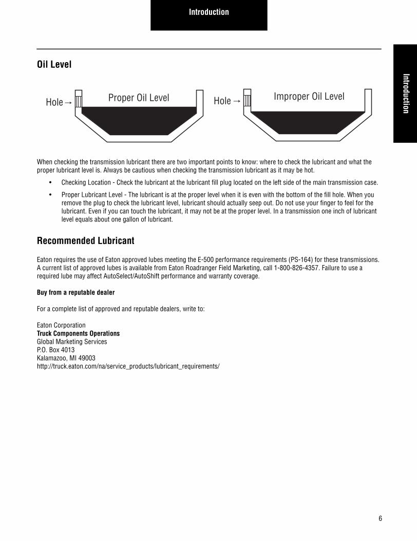
When checking the transmission lubricant there are two important points to know: where to check the lubricant and what the proper lubricant level is. Always be cautious when checking the transmission lubricant as it may be hot.
• Checking Location - Check the lubricant at the lubricant fill plug located on the left side of the main transmission case.
• Proper Lubricant Level - The lubricant is at the proper level when it is even with the bottom of the fill hole. When you remove the plug to check the lubricant level, lubricant should actually seep out. Do not use your finger to feel for the lubricant. Even if you can touch the lubricant, it may not be at the proper level. In a transmission one inch of lubricant level equals about one gallon of lubricant.
Recommended Lubricant
Eaton requires the use of Eaton approved lubes meeting the E-500 performance requirements (PS-164) for these transmissions. A current list of approved lubes is available from Eaton Roadranger Field Marketing, call 1-800-826-4357. Failure to use a required lube may affect AutoSelect/AutoShift performance and warranty coverage.
Buy from a reputable dealer
For a complete list of approved and reputable dealers, write to:
Eaton CorporationTruck Components OperationsGlobal Marketing ServicesP.O. Box 4013Kalamazoo, MI 49003http://truck.eaton.com/na/service_products/lubricant_requirements/
Improper Oil LevelHoleProper Oil LevelHole
6
Introduction
Preventive Maintenance Overview
To keep a vehicle running properly, it is important to perform preventive maintenance on the vehicle components. This insures the vehicle and its subassemblies will operate properly throughout their useful life. To cover preventive maintenance completely, you must review the following subjects in detail.
• Inspecting the Transmission
• Changing the Fluid
• Vehicle System Effects
Transmission Inspections
When performing preventive maintenance (PM) inspections, several items must be checked. It is important to perform every step to ensure the transmission meets its life expectancy. Proper PM consists of the following steps:
• Check the transmission oil level
• Inspect under the vehicle for loose/missing bolts
• Check the transmission for air leaks
• Check the transmission for lubricant leaks
Loose or Missing Bolts
While you are under the vehicle checking the lubricant, make a quick check for loose or missing bolts. Check all bolts on the back box, PTO covers, shift bar housing, clutch housing and transmission controller. Replace any missing or broken bolt with the proper bolt as called out in the illustrated parts listing. Follow the procedure defined in the manual transmission service manual when tightening any bolts.
Air Leaks
While you are under the vehicle, check for air leaks as well. The two steps when checking for an air leak are inspection and repair.
• Audible Inspection for Leaks - To find air leaks, make sure the vehicle air system has at least 90 PSI air pressure. Then, listen for leaks, making sure a vehicle leak is not mistaken for a transmission air leak.
• Refer to Troubleshooting Procedures for Repair - Once you find an air leak, use the troubleshooting guide to isolate the air leak to the faulty component.
Lubricant Leaks
Oil leak repair is very important. An lubricant leak could cause a catastrophic transmission failure. Check for leaks first at the gas-ket surfaces, the rear seal, and the transmission cooler.
Visual Check for Leaks at Gaskets
A visual check at each gasket to ensure that no leak is present. Typically a moist spot is acceptable; however drips or larger wet areas are not. Check for leaks at the rear housing, PTO, shift bar housing, shift tower, and clutch housing gasket surfaces. It is also Important to ensure that the leak is indeed coming from the transmission. Make sure the lubricant is not being blown back from the engine or another vehicle component.
7
IntroductionIntroduction
Check for Leaks Around the Input Shaft
Check for leaks around the input shaft. Leaks in this area could be caused by a faulty gasket, the input shaft, or pressurization of the main transmission case by the air system. If you find a leak at the input shaft, make sure the air system is not leaking into the case before looking for leaking gaskets.
Rear Seal
The rear seal is very important in maintaining lubricant in the transmission. If the seal is improperly installed or has failed, the transmission may experience a catastrophic failure. Check the rear seal by performing the following steps:
• Visual Check For Leak - Visually inspect the rear seal for a leak. If a rear seal leak is suspected, proper isolation is nec-essary.
• Verify the Leak Path - Other leaks may give the impression the rear seal is leaking. One possible cause is the vehicle speed sensor. Any lubricant leak above and in front of the rear seal could cause lubricant to collect around the seal. Wipe the seal with a clean rag, operate the vehicle, and recheck to verify the leak path. More information can be found in the rear seal maintenance guide (TRSM-0912).
Transmission Cooler Leaks
If the vehicle is equipped with a transmission lubricant cooler, make sure there are no leaks at the lubricant cooler, hoses, and fit-ting of the cooler circuit. Repair any cooler leaks as necessary.
Transmission Fluid Change
When it is time to change the transmission lubricant, there are only a few steps to follow: draining and filling the transmission, draining and filling the cooler (if equipped), and changing the oil filter (if equipped). Remember to be careful when changing the transmission lubricant, as it may be hot.
• Transmission Drain - Draining the transmission consists of removing the drain plug located on the bottom of the trans-mission case. Put a drain pan in place under the drain plug before removing it. Once the oil has finished draining, install the drain plug and torque to 45-55 Lb f ·ft. No sealant is required on the drain plug.
• Cooler Drain - If the vehicle is equipped with a transmission cooler, you must drain the cooler as well. To drain the cooler, remove both cooler lines at the transmission and pressurize one line with 30 PSI of air pressure. This will force the oil out of the cooler. Once the cooler has drained, reconnect the coolant lines to the transmission, making sure the lines are not crossed.
• Transmission Fill - Remove the transmission fill plug and fill the transmission with the desired approved oil. The trans-mission is full once oil starts flowing out of the fill hole. Replace the fill plug and torque to 60-70 Lb f ·ft.
• Cooler Fill - If the transmission is equipped with a cooler, the best way to fill the cooler is to place the transmission in neutral, start the vehicle, then release the clutch pedal so the input shaft of the transmission can rotate. This allows the pump to fill the cooler. Once the vehicle has run for about one minute, shut it off and recheck the transmission oil level.
• Filter Change - If the transmission is equipped with a spin-on oil filter, remove and replace the filter as you would any spin-on filter. It is also necessary to remove the filter when draining the oil from the cooler. As you unscrew the filter, catch the oil that seeps out between the filter opening and the "spin-on" casting.
8
Introduction
Vehicle System Effects
Some vehicle systems can affect transmission operation and possibly cause a failure. The major system that can affect AutoSe-lect or AutoShift is the air system.
Air System
If the air system is not given recommended preventive maintenance, it can cause transmission system problems. Although the transmission has an air filter regulator it cannot protect the transmission from contaminants indefinitely. This is why it is impor-tant to follow OEM recommendations for air system PM. It is important to regularly drain the air tanks and insure that oil is not being pumped by the air compressor into the vehicle air system. If moisture enters the transmission system, it may cause corro-sion. Also, in cold climates it may freeze, preventing the shift mechanisms from operating. If allowed into the system, oil could fill the air system components causing them to lose valuable air volume, slowing or preventing movement.
9
IntroductionIntroduction
Repair Warnings
When disassembling various assemblies, lay all parts on a clean bench in the same sequence as removed to simplify assembly and reduce the possibility of losing parts.
Provide a clean work area. Make sure no dirt or foreign material enter the unit during repair and assembly.
Disconnect the vehicle's battery before removing or installing electronic parts.
Since the cost of a new part is generally a small fraction of the total cost of downtime and labor, avoid reusing a questionable part that could lead to additional repairs and expense.
Use of other than recommended tools, parts, and instructions listed in this manual may place the safety of the service technician or vehicle driver in jeopardy.
The location of some components may vary with each O.E.M.
The removal and installation procedure described for each component may vary for your vehicle.
Always use genuine Eaton replacement parts. For a complete list of approved and reputable dealers, write to:
Eaton CorporationTruck Components OperationsGlobal Marketing ServicesP.O. Box 4013Kalamazoo, MI 49003http://truck.eaton.com/na/service_products/lubricant_requirements/
10

Introduction
11

12
Service ProcedureService Procedure
Reverse Ball Switch - Overview
Special Instructions
None.
Required Tools• Torque Wrench with 25 lb.ft. capacity.
Essential Steps
Install a new fiber washer.
Reverse Ball Switch
Service Procedure
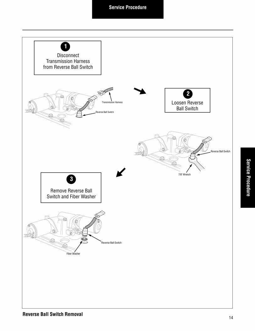
How to Remove the Reverse Ball Switch
Procedure-
1. Disconnect the Transmission Harness from the Reverse Ball Switch.
2. Using a 7/8" wrench, Loosen the Reverse Ball Switch.
3. Remove the Reverse Ball Switch and Fiber Washer from the Shift Bar Housing.
13
Service ProcedureService Procedure
Reverse Ball Switch
Fiber Washer
3
Remove Reverse BallSwitch and Fiber Washer
Reverse Ball Switch
7/8" Wrench
Reverse Ball Switch
Transmission Harness
2Loosen Reverse
Ball Switch
1Disconnect
Transmission Harnessfrom Reverse Ball Switch
14Reverse Ball Switch Removal

Service Procedure
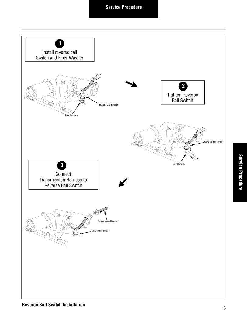
How to Install the Reverse Ball Switch
Procedure-
1. Install a new fiber washer (included in the Reverse Ball Switch service kit) on the Reverse Ball Switch.
2. Using a 7/8" wrench, install and tighten the Reverse Ball Switch to 20-25 lbs. ft. (27.1-33.9 N•m).
3. Connect the Transmission Harness to the Reverse Ball Switch.
Final Check
Verify Harness is locked.
15
Service ProcedureService Procedure
Reverse Ball Switch
Transmission Harness
3Connect
Transmission Harness toReverse Ball Switch
Reverse Ball Switch
7/8" Wrench
Reverse Ball Switch
Fiber Washer
2Tighten Reverse
Ball Switch
1Install reverse ball
Switch and Fiber Washer
16Reverse Ball Switch Installation

Service Procedure
Solo Heavy Duty Clutch - Install, Con’t
17

18
Service ProcedureService Procedure
Rail Select Sensor - Overview
Special Instructions
Install the sensor with the connector on top.
While removing or installing the capscrews, hold the sensor in place. Don't allow it to snap out of position.
Required Tools• Basic Hand Tools
Essential Steps
The shifter module must be calibrated before the vehicle is placed into operation.
Rail Select Sensor
Service Procedure
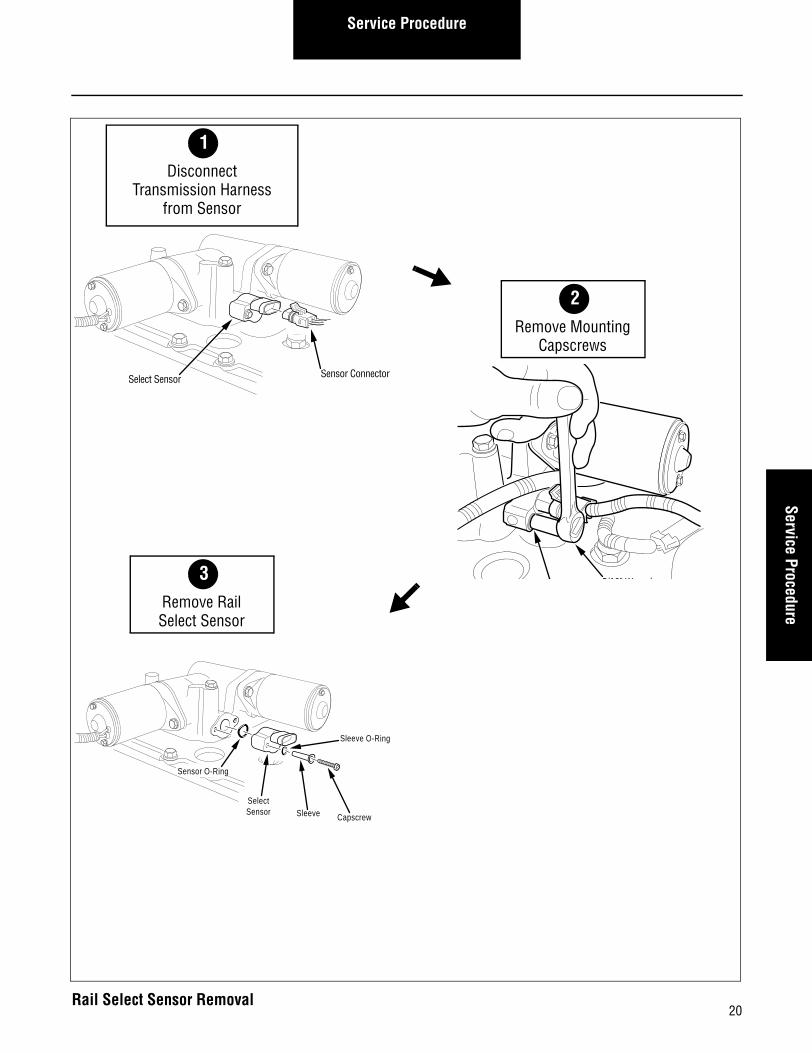
How to Remove the Rail Select Sensor
Procedure-
1. Disconnect the Transmission Harness from the Rail Select Sensor.
2. Using a 5/16" wrench, remove the two (2) sensor cap-screws.
3. Carefully allow the sensor to rotate (not snap) to a relaxed position. Then remove the sensor, steel sleeves and O-rings from the housing.
4. Insert your finger into the sensor bore and push the arm slightly.
19
Service ProcedureService Procedure
CapscrewSleeveSelectSensor
Sensor O-Ring
Sleeve O-Ring
3Remove RailSelect Sensor
5/16" Wrench
Select Sensor Sensor Connector
2Remove Mounting
Capscrews
1Disconnect
Transmission Harnessfrom Sensor
20Rail Select Sensor Removal
Service Procedure
How to Install the Rail Select Sensor
Procedure-
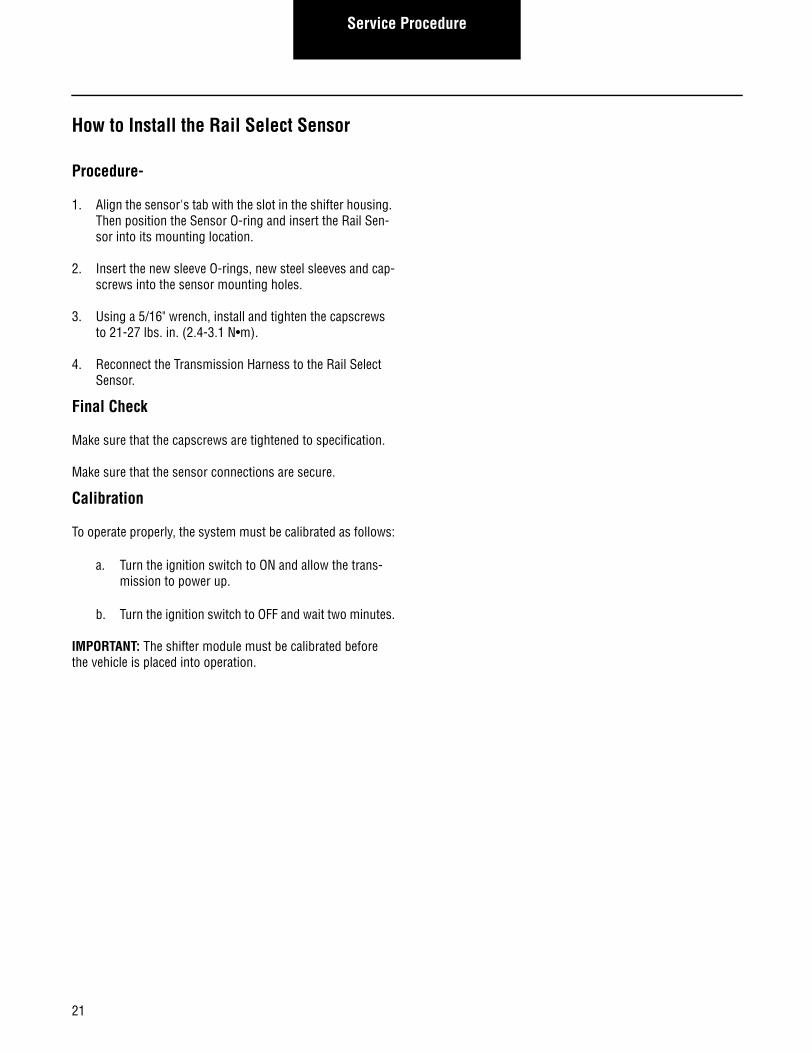
1. Align the sensor's tab with the slot in the shifter housing. Then position the Sensor O-ring and insert the Rail Sen-sor into its mounting location.
2. Insert the new sleeve O-rings, new steel sleeves and cap-screws into the sensor mounting holes.
3. Using a 5/16" wrench, install and tighten the capscrews to 21-27 lbs. in. (2.4-3.1 N•m).
4. Reconnect the Transmission Harness to the Rail Select Sensor.
Final Check
Make sure that the capscrews are tightened to specification.
Make sure that the sensor connections are secure.
Calibration
To operate properly, the system must be calibrated as follows:
a. Turn the ignition switch to ON and allow the trans-mission to power up.
b. Turn the ignition switch to OFF and wait two minutes.
IMPORTANT: The shifter module must be calibrated before the vehicle is placed into operation.
21
Service ProcedureService Procedure
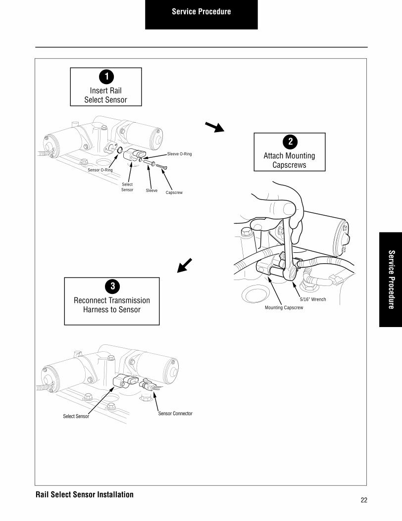
Select Sensor Sensor Connector
3Reconnect Transmission
Harness to Sensor Mounting Capscrew
5/16" Wrench
2
CapscrewSleeveSelectSensor
Sensor O-Ring
Sleeve O-Ring
2Attach Mounting
Capscrews
1Insert Rail
Select Sensor
22Rail Select Sensor Installation

Service Procedure
Solo Heavy Duty Clutch - Install, Con’t
23
24
Service ProcedureService Procedure
Gear Select Sensor - Overview
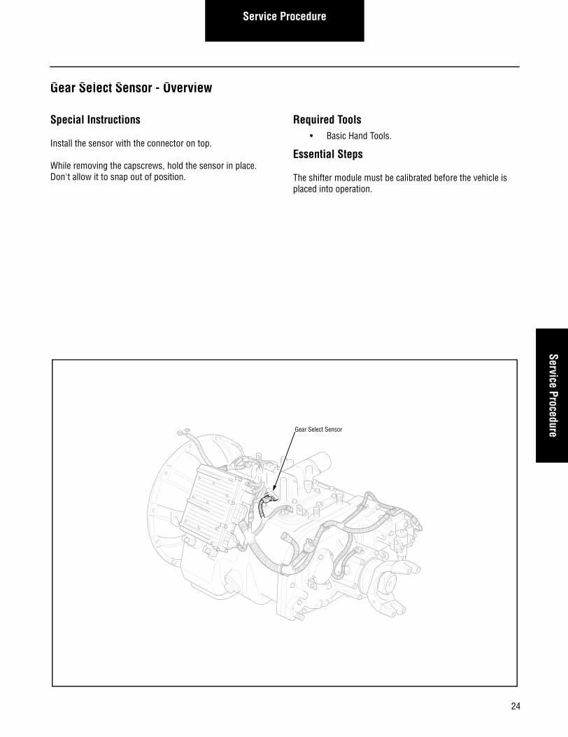
Special Instructions
Install the sensor with the connector on top.
While removing the capscrews, hold the sensor in place. Don't allow it to snap out of position.
Required Tools• Basic Hand Tools.
Essential Steps
The shifter module must be calibrated before the vehicle is placed into operation.
Gear Select Sensor
Service Procedure
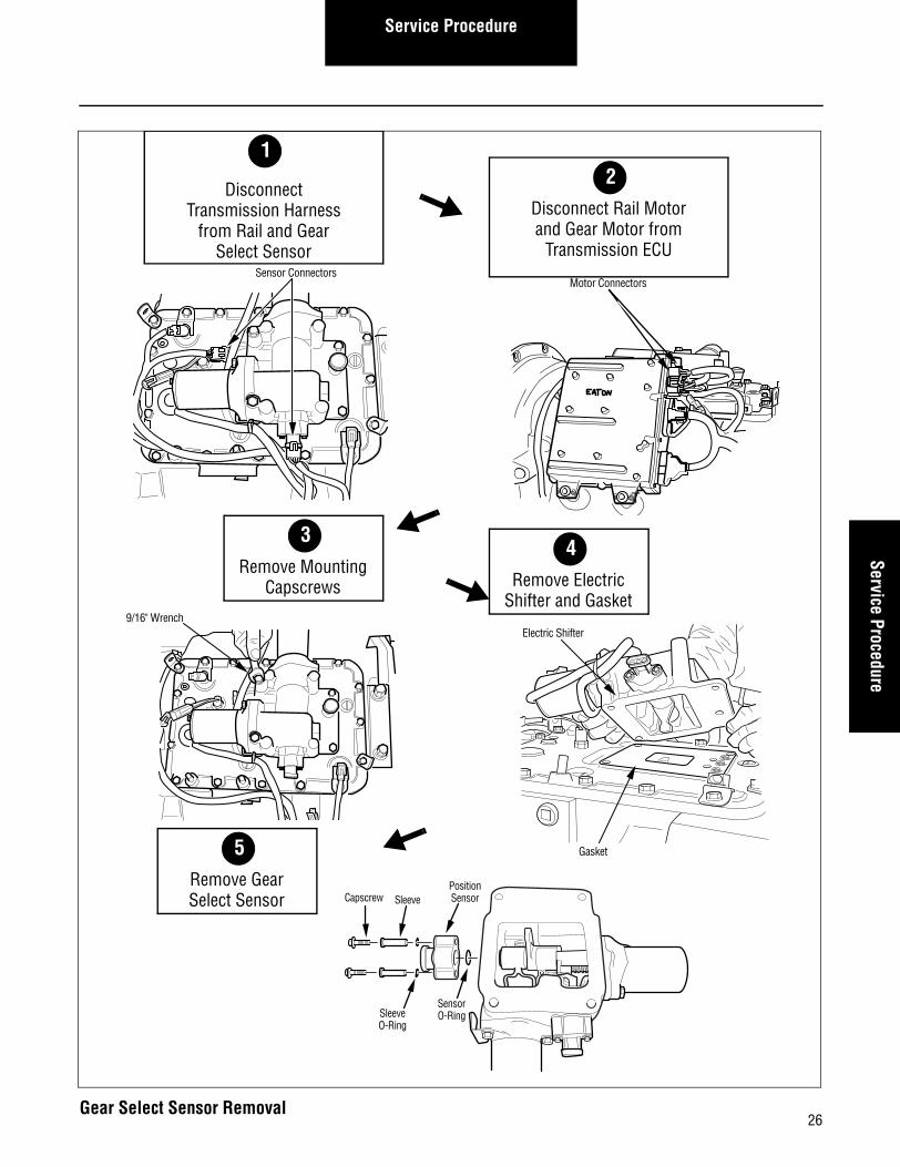
How to Remove the Gear Select Sensor
Procedure-
1. Remove nylon cable ties from motor wires.
2. Disconnect the Transmission Harness from the Gear Select Sensor and Rail Select Sensor.
3. Disconnect the Gear Select Motor and Rail Select Motor from the Transmission ECU.
4. Using a 5/16" wrench, remove the four (4) Electric Shifter capscrews.
5. Remove the Electric Shifter and gasket.
6. Turn the shifter over (upsidedown).
7. Using a 5/16" wrench, remove the two (2) Gear Select Sensor capscrews.
8. Carefully allow the sensor to rotate (not snap) to a relaxed position, then remove the sensor, steel sleeves and O-ring from the housing.
9. Insert your finger into the sensor bore and push the arm slightly.
25
Service ProcedureService Procedure
9/16" Wrench
3Remove Mounting
Capscrews
Motor Connectors
T
Sensor Connectors
2Disconnect Rail Motorand Gear Motor from
Transmission ECU
1
DisconnectTransmission Harness
from Rail and Gear Select Sensor
Electric Shifter
Gasket
Capscrew Sleeve
SleeveO-Ring
SensorO-Ring
PositionSensor
5Remove GearSelect Sensor
4Remove Electric
Shifter and Gasket
26Gear Select Sensor Removal

Service Procedure
How to Install the Gear Select Sensor
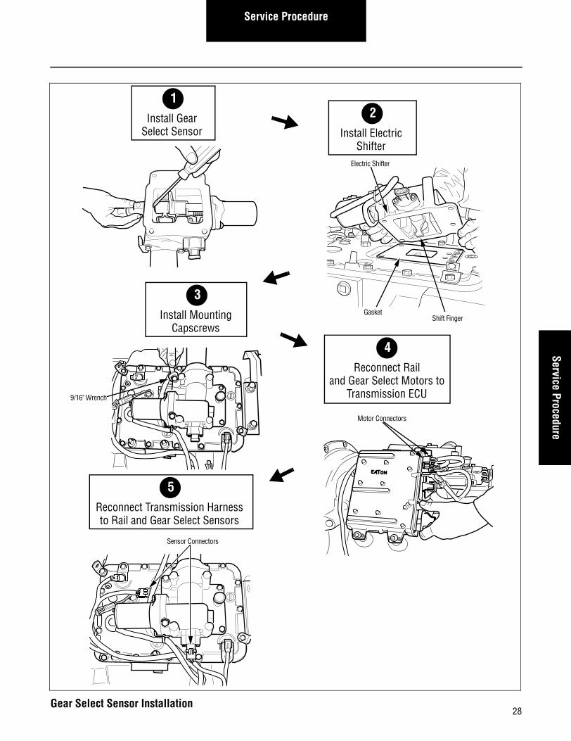
Procedure-
1. Using a screwdriver, push and hold the Gear Select bush-ing inside the Shift Bar Housing toward the outside of the housing.
2. While holding the bushing in place, align the sensor tab with the slot and insert the Gear Select Sensor into the shift shaft.
Note: Install the sensor with the connector toward the top of the Shifter Housing
3. Insert the new steel sleeves, O-rings and capscrews into the sensor mounting holes.
4. Using a 5/16" wrench, install and tighten the two (2) cap-screws to 21-27 lbs. in. (2.4-3.1 N•m).
5. Clean and remove old gasket material from the Shift Bar Housing.
6. Position a new gasket at the Shift Bar Housing mounting location.
Note: Check to make sure that the shift blocks are in the neutral position.
7. Move the shift finger in the Electric Shifter to the center (Neutral) position.
Note: If the shift finger is not properly aligned, the Elec-tric Shifter will not fit properly at its mounting location.
8. Position the Electric Shifter on the Shift Bar Housing.
9. Using a 9/16" wrench, install and tighten the four (4) cap-screws to 35-45 lbs. ft. (47.5-61.0 N•m).
10. Reconnect the Rail Select Motor to the Transmission ECU.
11. Reconnect the Gear Select Motor to the Transmission ECU.
12. Reconnect the Transmission Harness to the Rail Select Sensor and Gear Select Sensor.
13. Use nylon cable ties to secure the motor wires to the transmission.
Final Check
Make sure the capscrews are tightened to specification.
Make sure all connections are tight.
Calibration
To operate properly, the system must be calibrated as follows:
a. Turn the ignition switch to ON and allow the trans-mission to power up.
b. Turn the ignition switch to OFF and wait two minutes.
IMPORTANTThe shifter module must be calibrated before the vehicle is placed into operation.
27
Service ProcedureService Procedure
Motor Connectors
3Install Mounting
CapscrewsShift Finger
Gasket
Electric Shifter
3
2Install Electric
Shifter
1Install Gear
Select Sensor
5Reconnect Transmission Harnessto Rail and Gear Select Sensors
Sensor Connectors
T
9/16" Wrench
4Reconnect Rail
and Gear Select Motors to Transmission ECU
28Gear Select Sensor Installation

Service Procedure
Solo Heavy Duty Clutch - Install, Con’t
29

30
Service ProcedureService Procedure
Input/Main Shaft Speed Sensors - Overview
Special Instructions
Use care when installing the O-ring.
Lubricate the O-ring with Eaton/fuller silicone #71214 or equivalent.
Required Tools• Basic Hand tools.
Input ShaftSpeed Sensor
Mainshaft Speed Sensor
Output ShaftSpeed Sensor
Service Procedure
How to Remove the Input/Main Shaft Speed Sensors
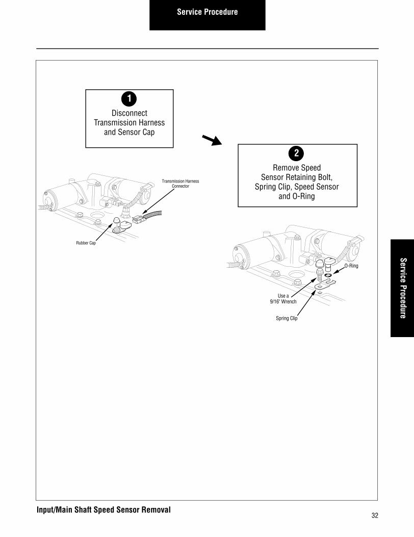
Procedure-
1. Disconnect the Transmission Harness from the Speed Sensor.
2. Remove the rubber cap from the retaining bolt.
Note: This cap is installed during manufacturing. It is NOT necessary to replace it.
3. Using a 9/16" wrench, remove the sensor retaining bolt.
4. Remove the spring clip.
5. Remove the Speed Sensor, with O-ring, from the trans-mission housing.
31
Service ProcedureService Procedure
Use a9/16" Wrench
O-Ring
Spring Clip
Transmission HarnessConnector
Rubber Cap
2Remove Speed
Sensor Retaining Bolt,Spring Clip, Speed Sensor
and O-Ring
1Disconnect
Transmission Harnessand Sensor Cap
32Input/Main Shaft Speed Sensor Removal
Service Procedure
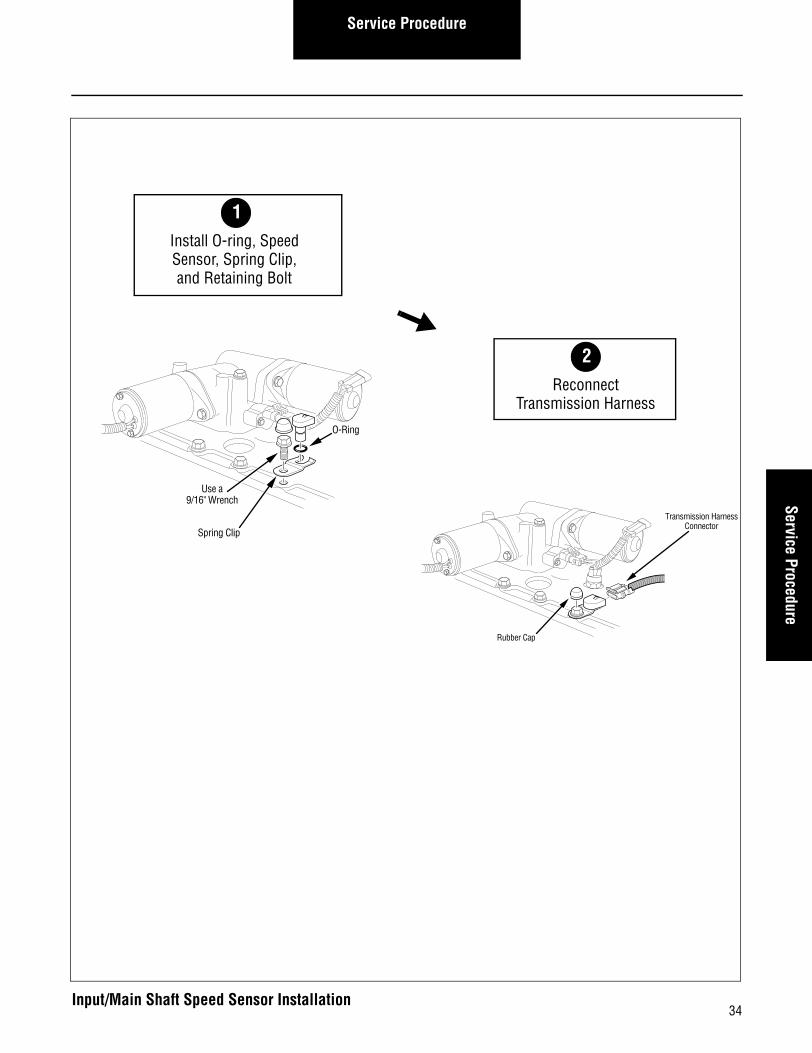
How to Install the Input/Main Shaft Speed Sensor
Procedure-
1. Using a smooth, twisting motion, fully insert the Speed Sensor in the transmission housing opening.
2. Install the spring clip.
3. Using a 9/16" wrench, install and tighten the retaining bolt to 35-45 lbs. ft. (47.5-61.0 N•m).
4. Reconnect the Transmission Harness to the Speed Sen-sor.
Final Check
Make sure the retaining bolt is properly tightened.
Make sure the Transmission Harness is properly connected to the Speed Sensor.
Calibration
None.
33
Service ProcedureService Procedure
Transmission HarnessConnector
Rubber Cap
Use a9/16" Wrench
O-Ring
Spring Clip
2Reconnect
Transmission Harness
1Install O-ring, SpeedSensor, Spring Clip, and Retaining Bolt
34Input/Main Shaft Speed Sensor Installation

Service Procedure
Solo Heavy Duty Clutch - Install, Con’t
35

36
Service ProcedureService Procedure
Output Shaft Speed Sensor - Overview
Special Instructions
Use extra care when installing the O-ring.
Lubricate the O-ring with Eaton/Fuller silicone #71214 or equivalent.
Required Tools• Basic Hand Tools.
Essential Steps
Make sure the retaining bolt is properly tightened.
Make sure the Transmission harness is properly connected to the Speed Sensor.
Input ShaftSpeed Sensor
Mainshaft Speed Sensor
Output ShaftSpeed Sensor

Service Procedure
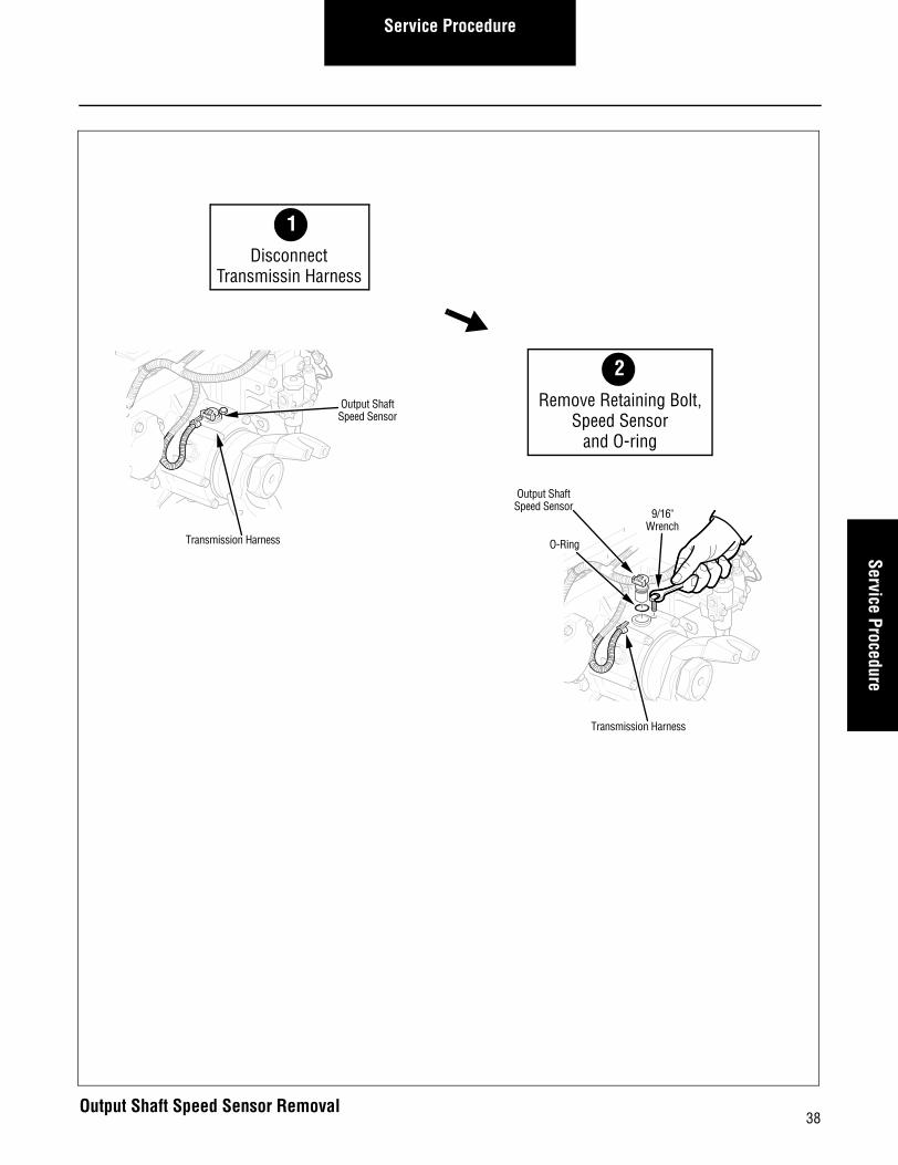
How to Remove the Output Shaft Speed Sensor
Procedure-
1. Disconnect the Transmission Harness from the Speed Sensor.
2. Using a 9/16" wrench, remove the sensor retaining bolt.
3. Remove the Speed Sensor, with O-ring, from the trans-mission housing.
37
Service ProcedureService Procedure
Transmission Harness
Output ShaftSpeed Sensor
O-Ring
9/16"Wrench
Transmission Harness
Output ShaftSpeed Sensor
2Remove Retaining Bolt,
Speed Sensor and O-ring
1Disconnect
Transmissin Harness
38Output Shaft Speed Sensor Removal

Service Procedure
How to Install the Output Shaft Speed Sensor
Procedure-
1. Using a smooth, twisting motion, fully insert the Speed Sensor in the transmission housing opening.
2. Using a 9/16" wrench, install and tighten the retaining bolt to 35-45 lbs. ft. (47.5-61.0 N•m).
3. Reconnect the Transmission Harness to the Speed Sen-sor.
Final Check
Make sure the retaining bolt is properly tightened.
Make sure the Transmission Harness is properly connected to the Speed Sensor.
Calibration
None.
39

Service ProcedureService Procedure
Transmission Harness
Output ShaftSpeed Sensor
Transmission Harness
Output ShaftSpeed Sensor
O-Ring
9/16"Wrench
2Reconnect
Transmission Harness
1Install O-ring,Speed Sensor
and Retaining Bolt
40Output Shaft Speed Sensor Installation

Service Procedure
Solo Heavy Duty Clutch - Install, Con’t
41

42
Service ProcedureService Procedure
Range Valve - Overview
Special Instructions
Do not use a hammer to loosen the Range Valve in the hous-ing.
Use caution when installing O-rings.
Lubricate O-rings with Eaton/Fuller silicone #71214 or equiva-lent.
Required Tools• Basic Hand Tools.
Essential Steps
None.
Range Valve
Service Procedure
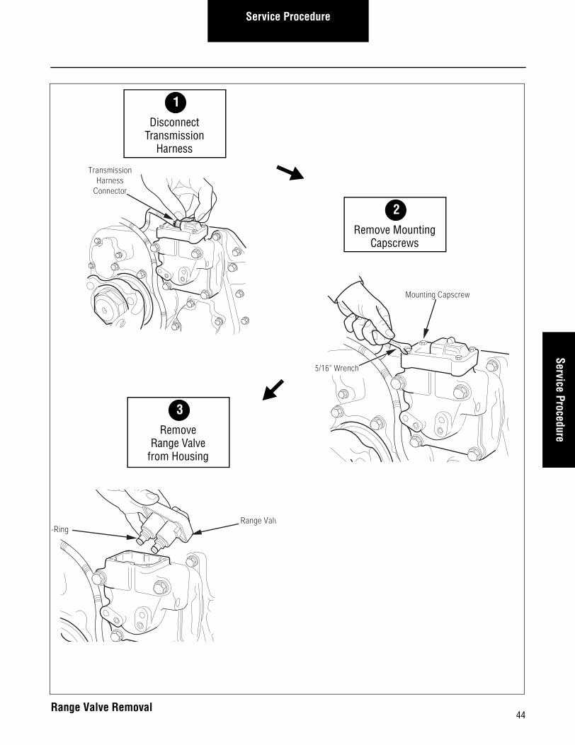
How to Remove the Range Valve
Procedure-
1. Relieve system air pressure by disconnecting vehicle air supply from the Air Filter/Regulator.
2. Disconnect the Transmission Harness from the Range Valve assembly.
3. Using a 5/16" wrench, remove the four (4) Range Valve capscrews.
4. Lift and remove the Range Valve from the transmission housing.
43
Service ProcedureService Procedure
Range Valv-Ring
3Remove
Range Valvefrom Housing
Mounting Capscrew
5/16" Wrench
2
TransmissionHarness
Connector
2Remove Mounting
Capscrews
1Disconnect
TransmissionHarness
44Range Valve Removal

Service Procedure
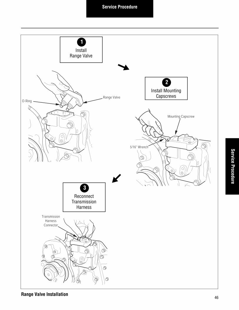
How to Install the Range Valve
Procedure-
1. Install and push the Range Valve down into the transmis-sion housing.
Note: The valve is keyed to fit its mounting location. Take care to align the slot in the valve with the slot in the transmission housing.
2. Using a 5/16" wrench, install and tighten the our (4) cap-screws to 21-27 lbs. in. (2.4-3.1 N•m).
3. Reconnect the Transmission Harness to the Range Valve.
4. Reconnect the air supply to the Air Filter/Regulator.
Final Check
Make sure that the capscrews are tightened to specification.
Make sure the Transmission Harness is connected and locked.
Calibration
None.
45
Service ProcedureService Procedure
TransmissionHarness
Connector
3Reconnect
TransmissionHarness
Mounting Capscrew
5/16" Wrench
2
Range ValveO-Ring
2Install Mounting
Capscrews
1Install
Range Valve
46Range Valve Installation

Service Procedure
Solo Heavy Duty Clutch - Install, Con’t
47

48
Service ProcedureService Procedure
Splitter Valve - Overview
Special Instructions
Do not use a hammer to loosen the Splitter Valve in the hous-ing.
Use caution when installing O-rings.
Lubricate O-rings with Eaton/Fuller silicone #71214 or equiva-lent.
Required Tools• Basic Hand Tools.
Essential Steps
None.
SplitterValve

Service Procedure
How to Remove the Splitter Valve
Procedure-
1. Relieve system air pressure by disconnecting vehicle air supply from the Air Filter/Regulator.
2. Disconnect the Transmission Harness from the Splitter Valve.
3. Using a 5/16" wrench, remove the four (4) Splitter Valve capscrews.
4. Lift and remove the Splitter Valve from the transmission housing.
49

Service ProcedureService Procedure
Splitter Valve
O-Ring
3Remove
Splitter Valvefrom Housing
5/16" Wrench
Mounting Capscrew
2
Transmission Harness Connector
2Remove Mounting
Capscrews
1Disconnect
TransmissionHarness
50Splitter Valve Removal
Service Procedure
How to Install the Splitter Valve
Procedure-
1. Install and push the Splitter Valve down into the trans-mission housing.
Note: The valve is keyed to fit its mounting location. Take care to align the slot in the valve with the slot in the transmission housing.
2. Using a 5/16" wrench, install and tighten the four (4) cap-screws to 21-27 lbs. in. (2.4-3.1 N•m).
3. Reconnect the Transmission Harness to the Splitter Valve.
4. Reconnect the air supply to the Air Filter/Regulator.
Final Check
Make sure the capscrews are properly tightened.
Make sure the Transmission Harness is connected and locked.
Calibration
None.
51

Service ProcedureService Procedure
Transmission Harness Connector
1
3Reconnect
TransmissionHarness
5/16" Wrench
Mounting Capscrew
2
Splitter Valve
O-Ring
2Install Mounting
Capscrews
1Install
Splitter Valve
52Splitter Valve Installation

Service Procedure
Solo Heavy Duty Clutch - Install, Con’t
53

54
Service ProcedureService Procedure
Air Filter/Regulator - Overview
Special Instructions
The Air Filter/Regulator has two (2) O-rings located between the filter/regulator and the Range Cylinder Cover..
Lubricate the O-rings with Eaton/Fuller Silicone #71214 or equivalent
Required Tools• Basic Hand Tools.
Essential Steps
None.
Air Filter/Regulator
Service Procedure
How to Remove the Air Filter/Regulator
Procedure-
1. Relieve system air pressure by disconnecting vehicle air supply from the Air Filter/Regulator.
2. Using a 7/16" wrench, remove the two (2) capscrews.
3. Remove the Air Filter/Regulator assembly.
4. Remove the two (2) O-rings from the recesses in the Range Cylinder Cover.
55

Service ProcedureService Procedure
O-Rings
Capscrews
7/16" Wrench
Air Filter/Regulator
2Remove O-Rings
1Remove Capscrews
56Air Filter/Regulator Removal
Service Procedure
How to Install the Air Filter/Regulator
Procedure-
1. Press the O-rings into the recesses in the Range Cylinder Cover.
2. Apply Eaton/Fuller sealant #71205 or equivalent to the two (2) retaining capscrews.
3. Insert the capscrews into the Air Filter/Regulator mount-ing holes.
4. Position the Air Filter/Regulator over the o-rings.
5. Using a 7/16" wrench, install and tighten the two (2) cap-screws to 8-12 lbs. ft. (10.8-16.3 N•m).
6. Reconnect the air supply to the Air Filter/Regulator.
Final Check
Make sure that the capscrews are properly tightened.
Make sure that all air supply fittings are tight.
Calibration
None.
57

Service ProcedureService Procedure
Capscrews
7/16" Wrench
Air Filter/Regulator
O-Rings
2Tighten Capscrews
1Position O-Rings
58Air Filter/Regulator Installation

Service Procedure
Solo Heavy Duty Clutch - Install, Con’t
59
60
Service ProcedureService Procedure
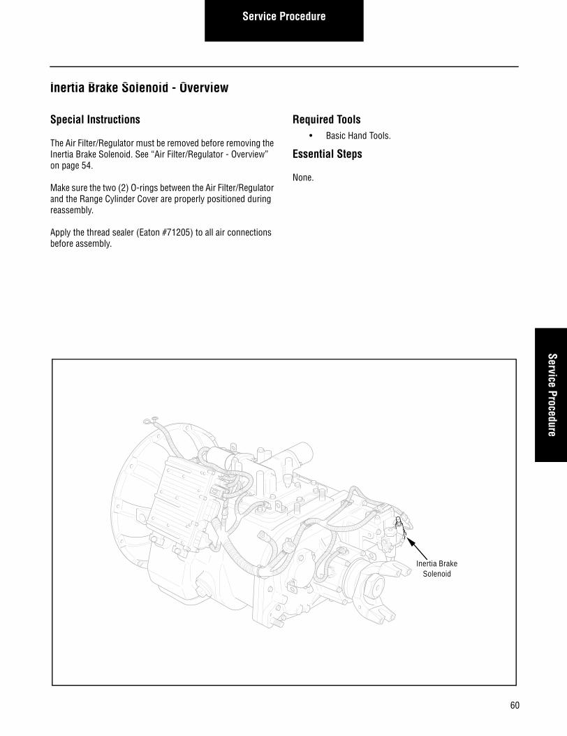
Inertia Brake Solenoid - Overview
Special Instructions
The Air Filter/Regulator must be removed before removing the Inertia Brake Solenoid. See “Air Filter/Regulator - Overview” on page 54.
Make sure the two (2) O-rings between the Air Filter/Regulator and the Range Cylinder Cover are properly positioned during reassembly.
Apply the thread sealer (Eaton #71205) to all air connections before assembly.
Required Tools• Basic Hand Tools.
Essential Steps
None.
Inertia BrakeSolenoid
Service Procedure
How to Remove the Inertia Brake Solenoid
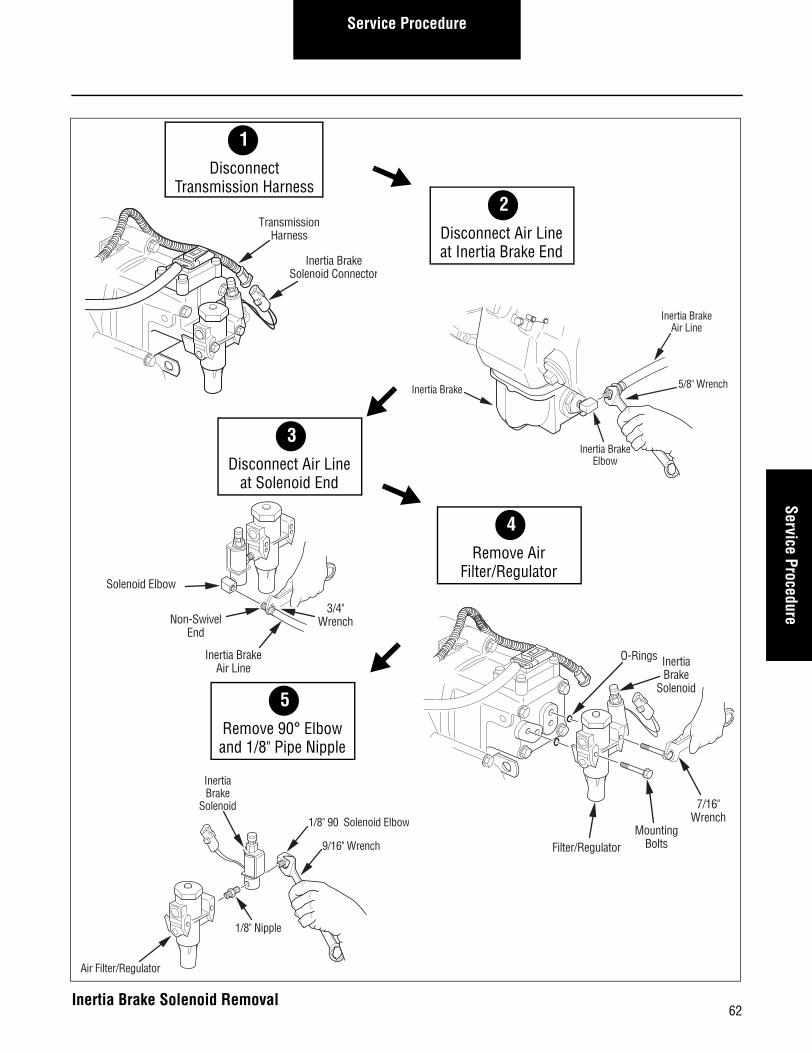
Procedure-
1. Relive system air pressure by disconnecting vehicle air supply from the Air filter/Regulator.
2. Disconnect the Transmission Harness from the Inertia Brake Solenoid.
3. Using a 5/8" wrench, disconnect the air from the Inertia Brake end (swivel end).
4. Using a 3/4" wrench, disconnect the air line at the sole-noid.
5. Using a 7/16" wrench, remove the Air filter/Regulator, with the solenoid attached from the Range Cylinder Cover.
Note: Remove and Inspect the two (2) O-rings from the recesses in the Range Cylinder Cover.
6. Remove the Inertia Brake Solenoid from the Air filter/Regulator.
7. Using a 9/16" wrench, remove the 1/8" 90° elbow from the Inertia Brake Solenoid and save it for installation on the new solenoid.
8. Using a 7/16" wrench, remove the 1/8" pipe nipple from the Inertia Brake Solenoid and save for installation on the solenoid.
61
Service ProcedureService Procedure
Solenoid Elbow
Inertia BrakeAir Line
3/4"WrenchNon-Swivel
End
3Disconnect Air Line
at Solenoid End
Inertia BrakeAir Line
5/8" Wrench
Inertia BrakeElbow
Inertia Brake
2
2Disconnect Air Lineat Inertia Brake End
1Disconnect
Transmission Harness
4Remove Air
Filter/Regulator
5Remove 90° Elbowand 1/8" Pipe Nipple
O-Rings InertiaBrake
Solenoid
MountingBolts
7/16"Wrench
Filter/Regulator
TransmissionHarness
Inertia BrakeSolenoid Connector
InertiaBrake
Solenoid
1/8" Nipple
Air Filter/Regulator
1/8" 90 Solenoid Elbow
9/16" Wrench
62Inertia Brake Solenoid Removal
Service Procedure
How to Install the Inertia Brake Solenoid
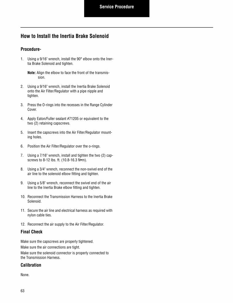
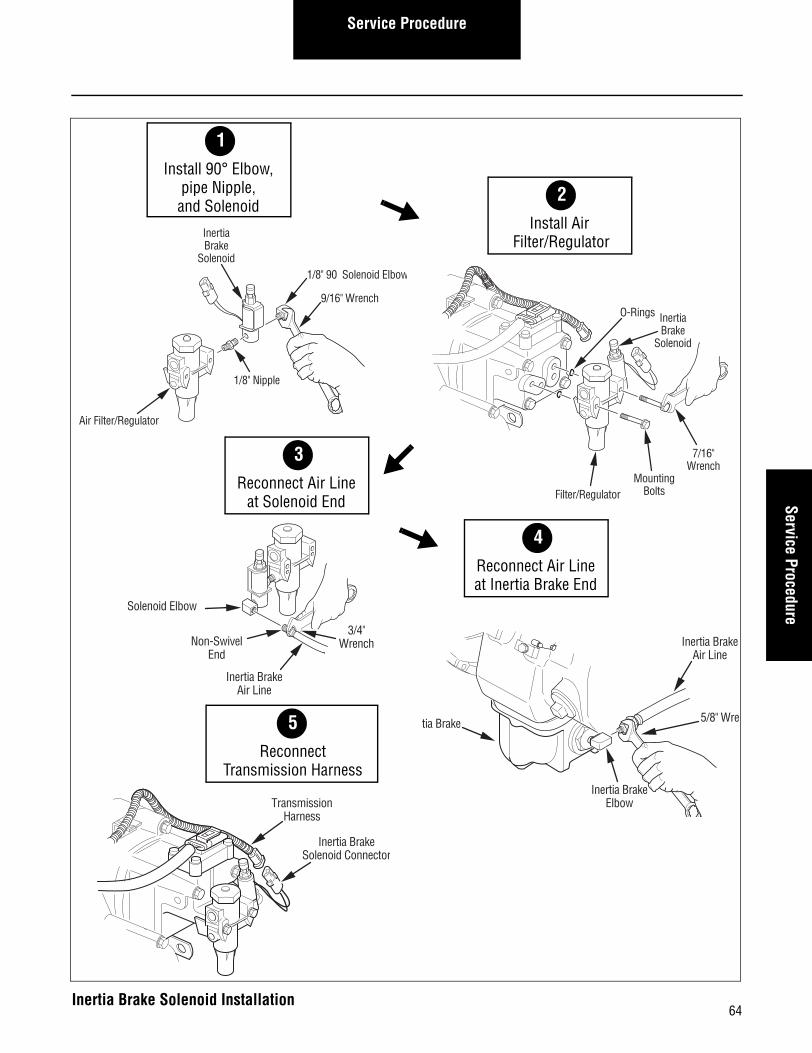
Procedure-
1. Using a 9/16" wrench, install the 90° elbow onto the Iner-tia Brake Solenoid and tighten.
Note: Align the elbow to face the front of the transmis-sion.
2. Using a 9/16" wrench, install the Inertia Brake Solenoid onto the Air Filter/Regulator with a pipe nipple and tighten.
3. Press the O-rings into the recesses in the Range Cylinder Cover.
4. Apply Eaton/Fuller sealant #71205 or equivalent to the two (2) retaining capscrews.
5. Insert the capscrews into the Air Filter/Regulator mount-ing holes.
6. Position the Air Filter/Regulator over the o-rings.
7. Using a 7/16" wrench, install and tighten the two (2) cap-screws to 8-12 lbs. ft. (10.8-16.3 N•m).
8. Using a 3/4" wrench, reconnect the non-swivel end of the air line to the solenoid elbow fitting and tighten.
9. Using a 5/8" wrench, reconnect the swivel end of the air line to the Inertia Brake elbow fitting and tighten.
10. Reconnect the Transmission Harness to the Inertia Brake Solenoid.
11. Secure the air line and electrical harness as required with nylon cable ties.
12. Reconnect the air supply to the Air Filter/Regulator.
Final Check
Make sure the capscrews are properly tightened.Make sure the air connections are tight.Make sure the solenoid connector is properly connected to the Transmission Harness.
Calibration
None.
63
Service ProcedureService Procedure
Solenoid Elbow
Inertia BrakeAir Line
3/4"WrenchNon-Swivel
End
O-Rings InertiaBrake
Solenoid
MountingBolts
7/16"Wrench
Filter/Regulator
InertiaBrake
Solenoid
1/8" Nipple
Air Filter/Regulator
1/8" 90 Solenoid Elbow
9/16" Wrench
2Install Air
Filter/Regulator
1Install 90° Elbow,
pipe Nipple,and Solenoid
3Reconnect Air Line
at Solenoid End
5Reconnect
Transmission Harness
4Reconnect Air Lineat Inertia Brake End
Inertia BrakeAir Line
5/8" Wre
Inertia BrakeElbow
rtia Brake
2
TransmissionHarness
Inertia BrakeSolenoid Connector
64Inertia Brake Solenoid Installation

Service Procedure
Solo Heavy Duty Clutch - Install, Con’t
65
66
Service ProcedureService Procedure
Inertia Brake - Overview
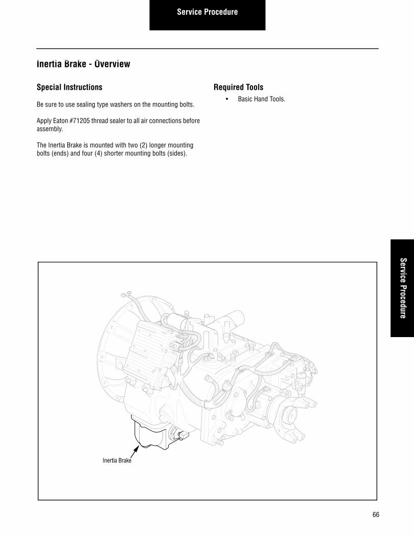
Special Instructions
Be sure to use sealing type washers on the mounting bolts.
Apply Eaton #71205 thread sealer to all air connections before assembly.
The Inertia Brake is mounted with two (2) longer mounting bolts (ends) and four (4) shorter mounting bolts (sides).
Required Tools• Basic Hand Tools.
Inertia Brake
Service Procedure
How to Remove the Inertia Brake
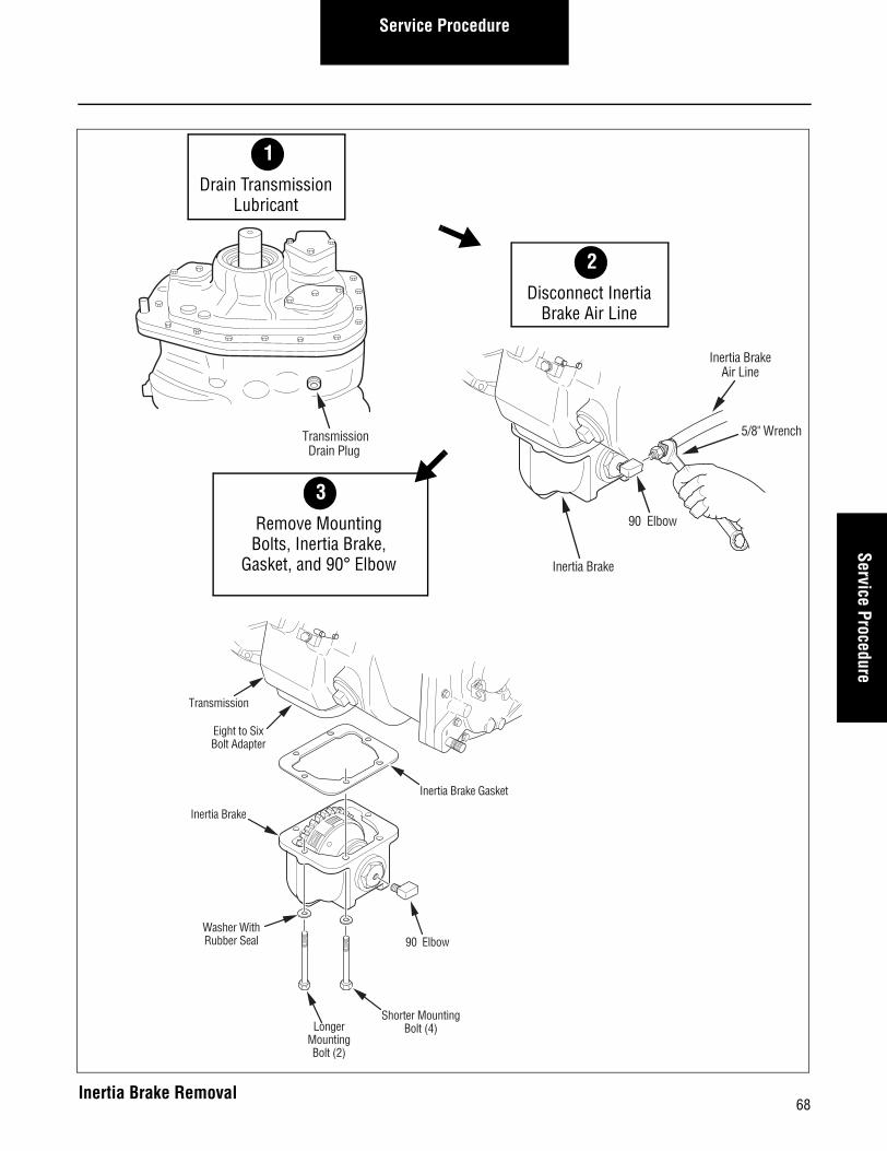
Procedure-
1. Drain the lubricant from the transmission.
Note: The Inertia Brake will still contain some lubricant.
2. Using a 5/8" wrench, disconnect the Inertia Brake air line from the 90 elbow.
3. Using a 9/16" wrench, remove the six (6) mounting bolts, with sealing washers, from the Inertia Brake.
4. Remove the Inertia Brake and gasket from the transmis-sion.
5. Using a 9/16" wrench, remove the 90 elbow from the Inertia Brake.
67
Service ProcedureService Procedure
Transmission
Eight to SixBolt Adapter
Inertia Brake Gasket
Inertia Brake
Washer WithRubber Seal
LongerMountingBolt (2)
Shorter MountingBolt (4)
90 Elbow
3Remove MountingBolts, Inertia Brake,
Gasket, and 90° Elbow
Inertia BrakeAir Line
90 Elbow
5/8" Wrench
Inertia Brake
TransmissionDrain Plug
2Disconnect Inertia
Brake Air Line
1Drain Transmission
Lubricant
68Inertia Brake Removal
Service Procedure
How to Install the Inertia Brake
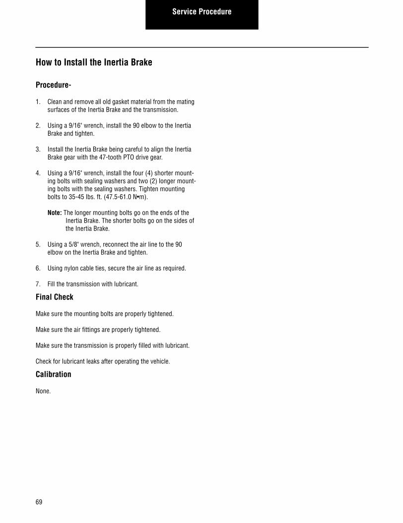
Procedure-
1. Clean and remove all old gasket material from the mating surfaces of the Inertia Brake and the transmission.
2. Using a 9/16" wrench, install the 90 elbow to the Inertia Brake and tighten.
3. Install the Inertia Brake being careful to align the Inertia Brake gear with the 47-tooth PTO drive gear.
4. Using a 9/16" wrench, install the four (4) shorter mount-ing bolts with sealing washers and two (2) longer mount-ing bolts with the sealing washers. Tighten mounting bolts to 35-45 lbs. ft. (47.5-61.0 N•m).
Note: The longer mounting bolts go on the ends of the Inertia Brake. The shorter bolts go on the sides of the Inertia Brake.
5. Using a 5/8" wrench, reconnect the air line to the 90 elbow on the Inertia Brake and tighten.
6. Using nylon cable ties, secure the air line as required.
7. Fill the transmission with lubricant.
Final Check
Make sure the mounting bolts are properly tightened.
Make sure the air fittings are properly tightened.
Make sure the transmission is properly filled with lubricant.
Check for lubricant leaks after operating the vehicle.
Calibration
None.
69
Service ProcedureService Procedure
TransmissionFill Plug
3Fill Transmissionwith Lubricant
5/8" Wrench
Transmission
Eight to SixBolt Adapter
Inertia Brake Gasket
Inertia Brake
Washer WithRubber Seal
LongerMountingBolt (2)
Shorter MountingBolt (4)
90 Elbow
2Reconnect Inertia
Brake Air Line
1Install 90° Elbow,
Inertia Brake, Gasketand Mounting bolts
70Inertia Brake Installation

Service Procedure
Solo Heavy Duty Clutch - Install, Con’t
71

72
Service ProcedureService Procedure
Power Module - Overview
Special Instructions
Disconnect Batteries before performing this procedure.
Required Tools• Basic Hand Tools.
Power Module(Behind ECU)
Service Procedure
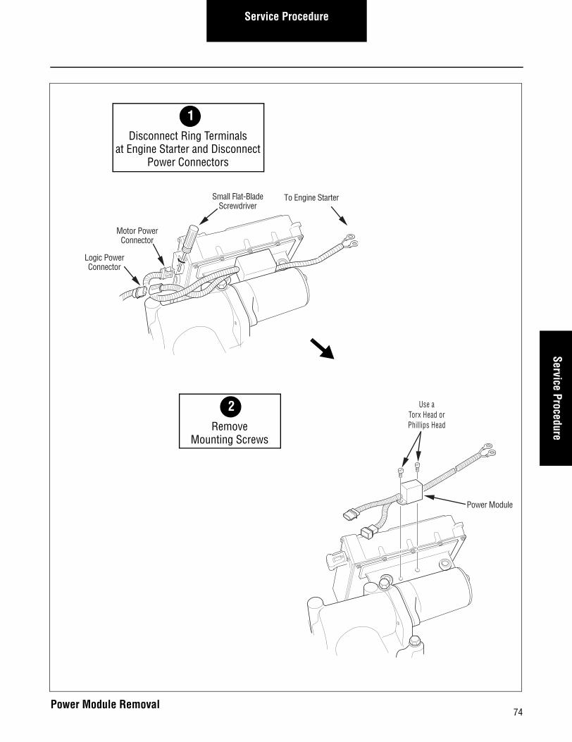
How to Remove the Power Module
Procedure-
1. Remove the two (2) 1/2" ring terminals from the starter (in the engine compartment).
2. Use a small flat-blade screwdriver to pry and disconnect the Motor Power connector from the Transmission ECU.
3. Disconnect the Logic Power connector from the Trans-mission Harness.
4. Using a phillips head or torx head screwdriver, remove the two (2) Power Module mounting screws.
5. Lift the Power Module assembly up and away from the transmission.
73
Service ProcedureService Procedure
Use aTorx Head orPhillips Head
Power Module
Small Flat-BladeScrewdriver
Motor PowerConnector
Logic PowerConnector
To Engine Starter
2Remove
Mounting Screws
1Disconnect Ring Terminals
at Engine Starter and DisconnectPower Connectors
74Power Module Removal
Service Procedure
How to Install the Power Module
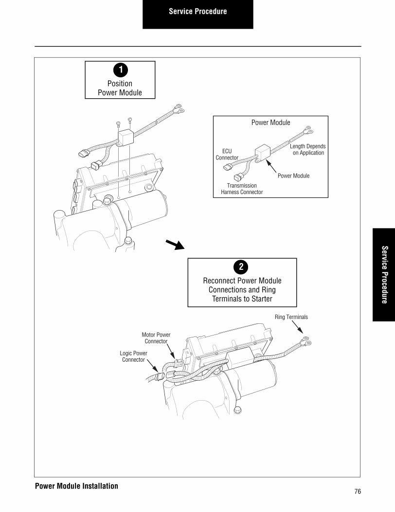
Procedure-
1. Position the Power Module at its mounting location.
2. Use a phillips head or torx head screwdriver to install and tighten the two (2) mounting screws.
3. Reconnect the Motor Power connector to the Transmis-sion ECU.
4. Reconnect the Logic Power connector to the Transmis-sion Harness.
5. Reconnect the two (2) 1/2" ring terminals to the engine starter.
Note: Observe proper polarity when connecting the ter-minals to the starter (red for positive and black for negative).
Final Check
Verify mounting screws are properly tightened.
Calibration
None.
75
Service ProcedureService Procedure
Motor PowerConnector
Logic PowerConnector
Ring Terminals
Length Depends on ApplicationECU
Connector
TransmissionHarness Connector
Power Module
Power Module
2Reconnect Power Module
Connections and Ring Terminals to Starter
1Position
Power Module
76Power Module Installation

Service Procedure
Solo Heavy Duty Clutch - Install, Con’t
77

78
Service ProcedureService Procedure
Electric Shifter - Overview
Special Instructions
Make sure the three (3) sets of detent balls and springs are installed properly in the Shift Bar Housing.
Required Tools• Basic Hand Tools.
Essential Steps
IMPORTANT: The shifter module must be calibrated before the vehicle is placed into operation.
Electric Shifter
Service Procedure
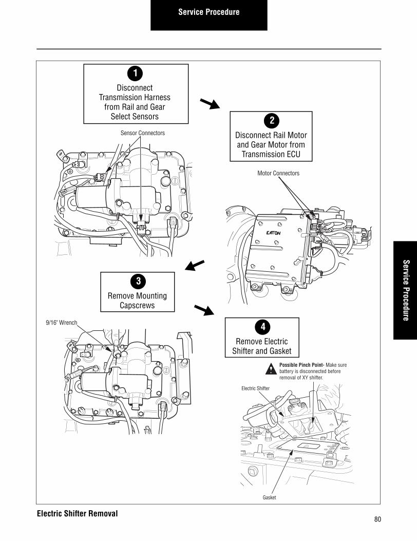
How to Remove the Electric Shifter
Procedure-
1. Remove nylon cable ties from the motor wires.
2. Disconnect the Transmission Harness from the Rail Select Sensor and the Gear Select Sensor.
3. Disconnect the Rail Select Motor from the Transmission ECU.
4. Disconnect the Gear Select Motor from the Transmission ECU.
5. Using a 9/16" wrench, remove the four (4) capscrews.
6. Remove the Electric Shifter and gasket.
79
Service ProcedureService Procedure
Electric Shifter
Gasket
Possible Pinch Point- Make surebattery is disconnected before removal of XY shifter.
4Remove Electric
Shifter and Gasket
Motor Connectors
Sensor Connectors
2Disconnect Rail Motorand Gear Motor from
Transmission ECU
1Disconnect
Transmission Harnessfrom Rail and Gear
Select Sensors
3Remove Mounting
Capscrews
9/16" Wrench
80Electric Shifter Removal
Service Procedure
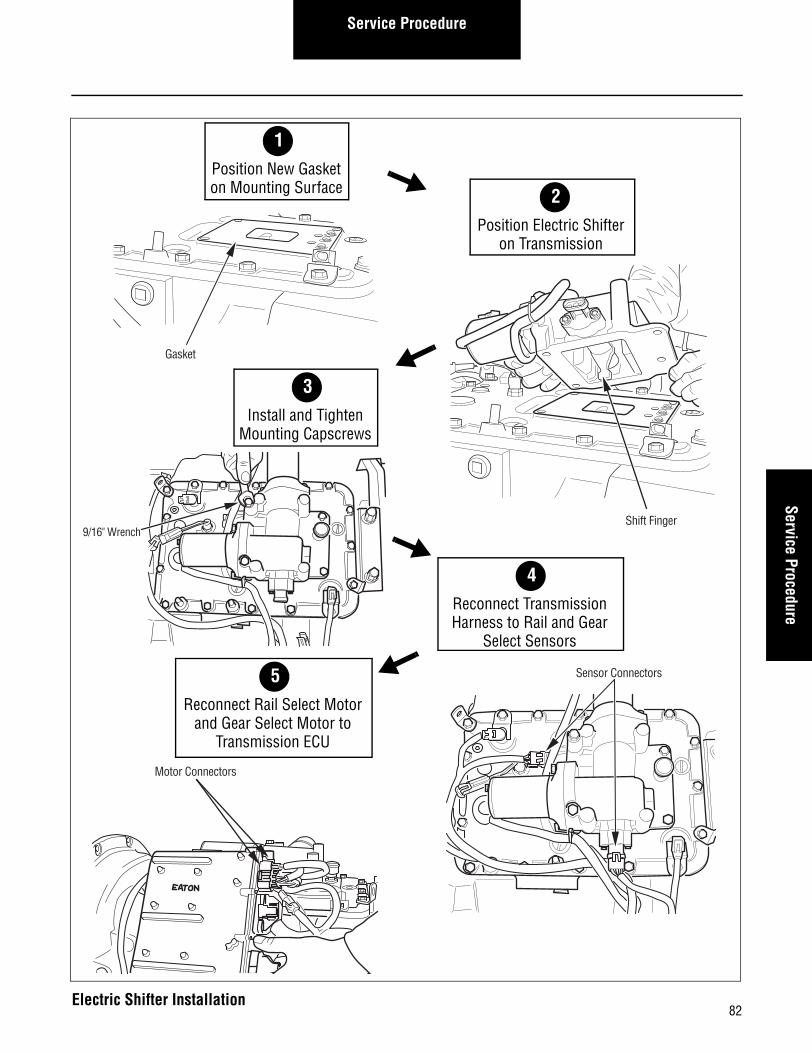
How to Install the Electric Shifter
Procedure-
1. Clean and remove old gasket material from the Shift Bar Housing.
2. Position a new gasket at the Electric Shifter mounting location.
3. Check to ensure that the shift blocks are in the Neutral position.
4. Move the shift finger to the center (NEUTRAL) location.
Note: If the shift finger is not properly aligned, the Elec-tric Shifter will not fit properly at its mounting location.
5. Position the Electric Shifter on the Shift Bar Housing.
6. Using a 9/16" wrench, install and tighten the capscrews to 35-45 lbs. ft. (47.5-61.0 N•m).
7. Reconnect the Transmission Harness to the Rail Select Sensor and Gear Select Sensor.
8. Reconnect the Rail Select Motor to the Transmission ECU.
9. Reconnect the Gear Select Motor to the Transmission ECU.
10. Using nylon cable ties, secure the motor wires to the transmission in their previous position.
Final Check
Make sure that the capscrews are tightened to specification.
Make sure all Electric Shifter connectors are securely attached.
Calibration
To operate properly, the system must be calibrated as follows:
a. Turn the ignition switch to ON and allow the trans-mission to power up.
b. Turn the ignition switch to OFF and wait two minutes.
IMPORTANT: The shifter module must be calibrated before the vehicle is placed into operation.
81
Service ProcedureService Procedure
9/16" Wrench
3Install and Tighten
Mounting Capscrews
Shift Finger
Gasket
2Position Electric Shifter
on Transmission
1Position New Gasketon Mounting Surface
Sensor Connectors5Reconnect Rail Select Motor
and Gear Select Motor to Transmission ECU
4Reconnect Transmission Harness to Rail and Gear
Select Sensors
Motor Connectors
82Electric Shifter Installation

Service Procedure
83

84
Service ProcedureService Procedure
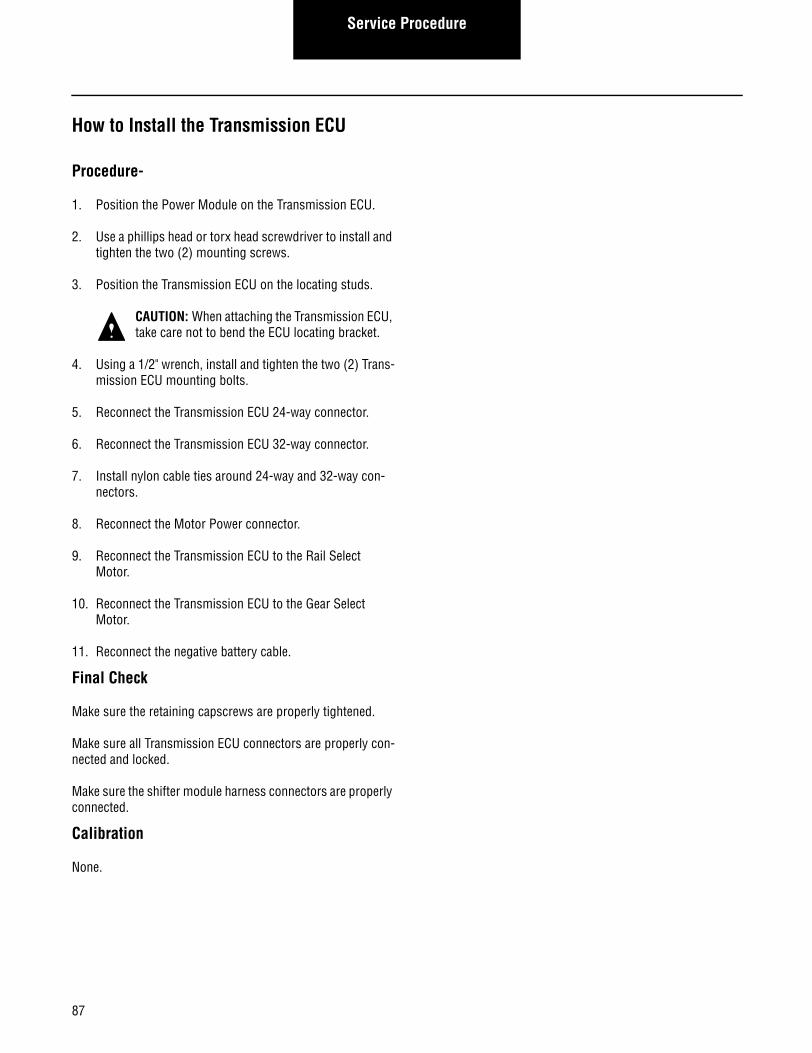
Transmission ECU - Overview
Special Instructions
Install the Power Module on the Transmission ECU before installing the Transmission ECU.
Apply lubricant to the ECU mounting bracket locating studs on the main case top.
Make sure the three (3) 2-pin packard connectors are properly located on the Transmission ECU top.
Required Tools• Basic Hand Tools.
Transmission ECU
Service Procedure
How to Remove the Transmission ECU
Procedure-
1. Disconnect the negative battery cable.
2. Remove nylon cable ties from ECU 24-way and 32-way connectors.
3. Disconnect the Gear Select Motor from the Transmission ECU.
4. Disconnect the Rail Select Motor from the Transmission ECU.
5. Use a small flat-blade screwdriver to unlock and discon-nect the Motor Power connector.
6. Unlock and disconnect the Transmission ECU 32-way connector.
7. Unlock and disconnect the Transmission ECU 24-way connector.
8. Using a 1/2" wrench, remove the two (2) Transmission ECU mounting bolts.
9. Remove the Transmission ECU assembly from the locat-ing studs.
CAUTION: When removing the Transmission ECU, take care not to bend the ECU locating bracket.
10. Using a phillips head or torx head screwdriver, remove the Power Module mounting screws.
11. Remove the Power Module and lay it on the transmis-sion.
85

Service ProcedureService Procedure
Locating Studs
4Remove
Power Module
1/2" Wrench
Transmission ECU Connectors
2Remove Mounting
Capscrews
1Disconnect Five
Transmission ECUconnectors
3Remove
Transmission ECU
Power Module Screws
86Transmission ECU Removal
Service Procedure
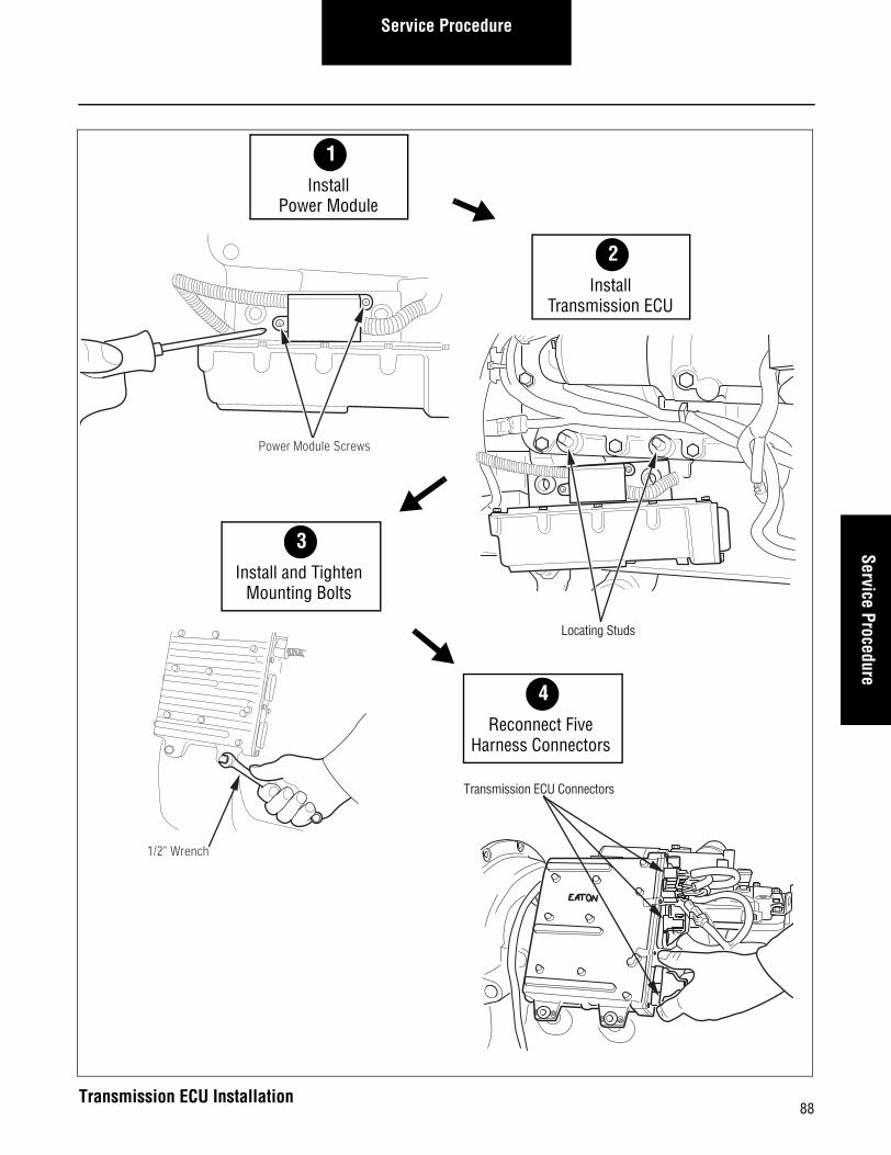
How to Install the Transmission ECU
Procedure-
1. Position the Power Module on the Transmission ECU.
2. Use a phillips head or torx head screwdriver to install and tighten the two (2) mounting screws.
3. Position the Transmission ECU on the locating studs.
CAUTION: When attaching the Transmission ECU, take care not to bend the ECU locating bracket.
4. Using a 1/2" wrench, install and tighten the two (2) Trans-mission ECU mounting bolts.
5. Reconnect the Transmission ECU 24-way connector.
6. Reconnect the Transmission ECU 32-way connector.
7. Install nylon cable ties around 24-way and 32-way con-nectors.
8. Reconnect the Motor Power connector.
9. Reconnect the Transmission ECU to the Rail Select Motor.
10. Reconnect the Transmission ECU to the Gear Select Motor.
11. Reconnect the negative battery cable.
Final Check
Make sure the retaining capscrews are properly tightened.
Make sure all Transmission ECU connectors are properly con-nected and locked.
Make sure the shifter module harness connectors are properly connected.
Calibration
None.
87
Service ProcedureService Procedure
1/2" Wrench
3Install and Tighten
Mounting Bolts
Locating Studs
Power Module Screws
2Install
Transmission ECU
1Install
Power Module
Transmission ECU Connectors
4Reconnect Five
Harness Connectors
88Transmission ECU Installation

Service Procedure
Solo Heavy Duty Clutch - Install, Con’t
89

90
Service ProcedureService Procedure
Transmission Harness - Overview
Special Instructions
Make sure the three (3) two pin packard connectors are prop-erly located on the Transmission ECU top.
Required Tools• Basic Hand Tools.
Transmission Harness

Service Procedure
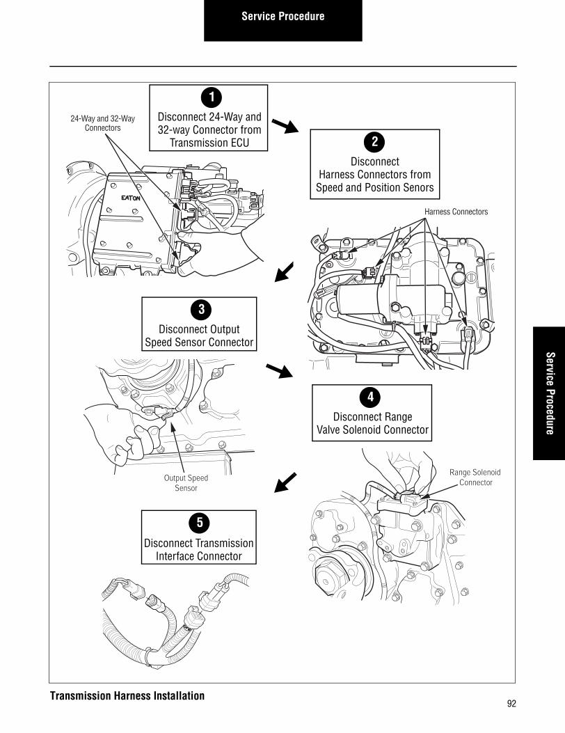
How to Remove the Transmission Harness
Procedure-
1. Remove nylon cable ties holding the harness and con-nectors in place.
2. Disconnect 32-way and 24-way ECU connectors from the ECU
3. Disconnect Input and Main Shaft Speed Sensors
4. Disconnect Gear Select Sensor and Rail Select Sensor
5. Disconnect Reverse Ball Switch
6. Disconnect Logic Power from the Transmission Harness
7. Disconnect Output Shaft Speed Sensor
8. Disconnect Range Solenoid Valve
9. Disconnect Transmission Interface connector
10. If required, disconnect the Splitter Solenoid and Inertia Brake Solenoid.
11. Remove the Transmission Harness.
91
Service ProcedureService Procedure
Output SpeedSensor
3Disconnect Output
Speed Sensor Connector
Harness Connectors
24-Way and 32-WayConnectors
2Disconnect
Harness Connectors from Speed and Position Senors
1Disconnect 24-Way and32-way Connector from
Transmission ECU
4Disconnect Range
Valve Solenoid Connector
Range Solenoid Connector
5
Disconnect TransmissionInterface Connector
92Transmission Harness Installation

Service Procedure
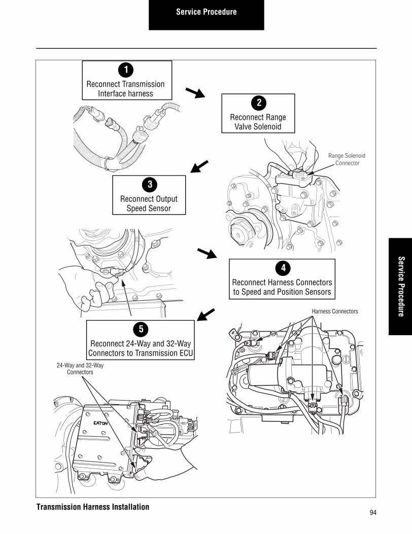
How to Install the Transmission Harness
Procedure-
1. Route the pigtail harness that comes off the 32-way con-nector behind the Transmission ECU and up to the top of the transmission.
2. If required, reconnect the Splitter Solenoid and Inertia Brake Solenoid.
3. Reconnect the Transmission Interface connector
4. Reconnect the Range Solenoid Valve
5. Reconnect the Output Shaft Speed Sensor
6. Reconnect the Logic Power from the Transmission Har-ness
7. Reconnect the Reverse Ball Switch
8. Reconnect the Gear Select Sensor and Rail Select Sensor
9. Reconnect the Input and Main Shaft Speed Sensors
10. Reconnect the 32-way and 24-way ECU connectors to the Transmission ECU
11. Replace all nylon cable ties to hold the Transmission Har-ness and connectors in place.
Final Check
Double-check all connections to make sure they are secure.
Calibration
None.
93
Service ProcedureService Procedure
3
3Reconnect Output
Speed Sensor
Range Solenoid Connector
2Reconnect Range
Valve Solenoid
1Reconnect Transmission
Interface harness
4Reconnect Harness Connectorsto Speed and Position Sensors
5Reconnect 24-Way and 32-Way
Connectors to Transmission ECU
Harness Connectors
24-Way and 32-WayConnectors
94Transmission Harness Installation

Service Procedure
Solo Heavy Duty Clutch - Install, Con’t
95

96
Service ProcedureService Procedure
Shift Lever - Overview
Special Instructions
None.
Required Tools• Basic Hand Tools.
Service Procedure
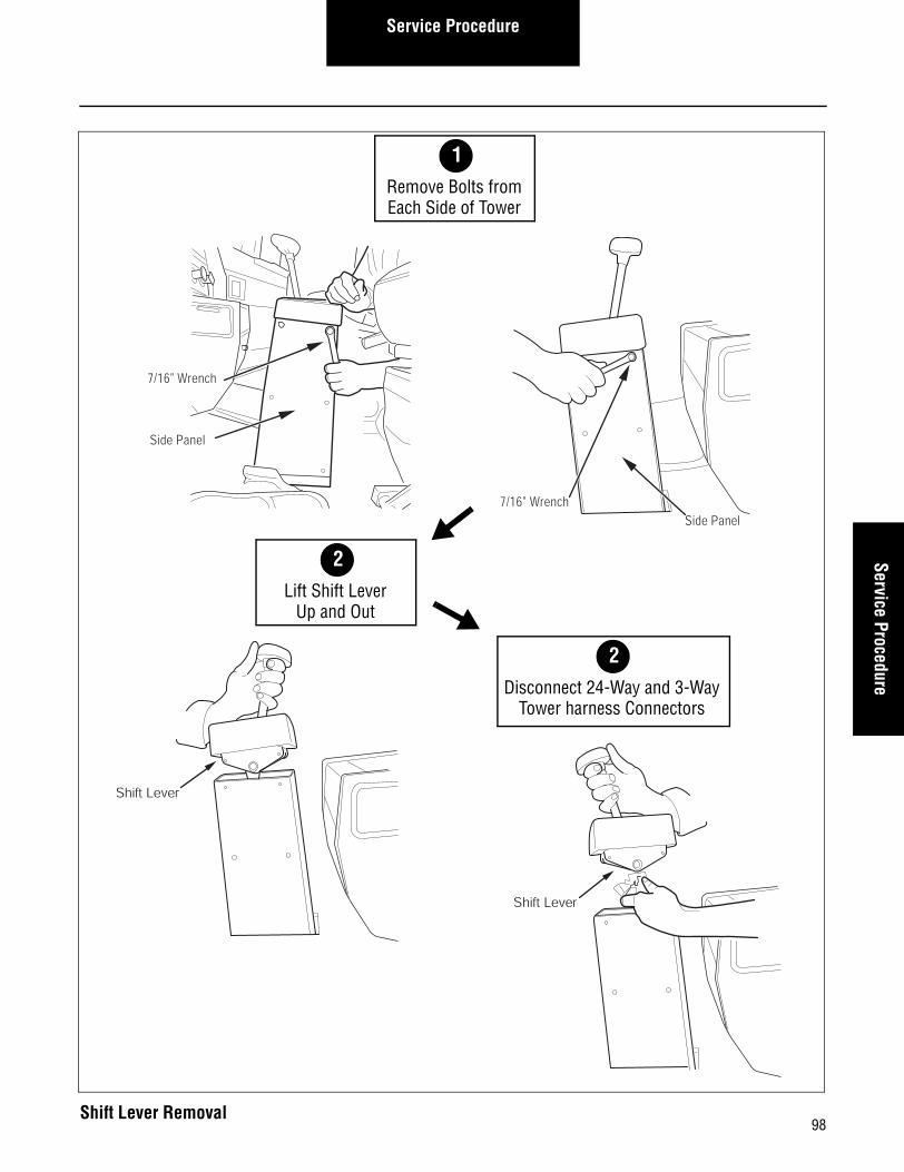
How to Remove the Shift Lever
Procedure-
1. Using a 7/16" wrench, remove the two (2) bolts from one side of the Shift Lever.
2. Using a 7/16" wrench, remove the other two (2) bolts from the other side of the Shift Lever.
3. Lift the Shift Lever out of the Shift Tower.
4. Disconnect the 24-way connector and the 3-way Tower Harness connectors.
5. Remove the Shift Lever.
97
Service ProcedureService Procedure
Shift Lever
2
2Lift Shift Lever
Up and Out
7/16" WrenchSide Panel
Side Panel
7/16" Wrench
1Remove Bolts fromEach Side of Tower
2Disconnect 24-Way and 3-Way
Tower harness Connectors
Shift Lever
98Shift Lever Removal
Service Procedure
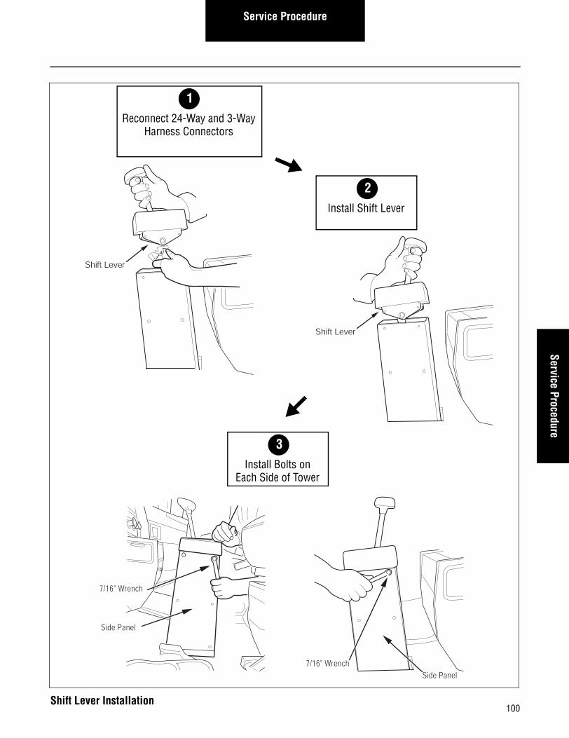
How to Install the Shift Lever
Procedure-
1. Reconnect the 24-way and 3-way Tower Harness connec-tors.
2. Position the Shift Lever assembly on its mounting sur-face.
3. Apply blue loctite #242 to the four (4) mounting bolts.
4. Using a 7/16" wrench, install and tighten the bolts to 6-8 lbs. ft. (8.1-10.8 N•m).
Final Check
Make sure the mounting bolts are properly torqued.
Calibration
None.
99
Service ProcedureService Procedure
Side Panel
7/16" Wrench
3Install Bolts on
Each Side of Tower
Shift Lever
2
Shift Lever
2Install Shift Lever
1Reconnect 24-Way and 3-Way
Harness Connectors
7/16" WrenchSide Panel
100Shift Lever Installation

Service Procedure
Solo Heavy Duty Clutch - Install, Con’t
101
102
Service ProcedureService Procedure
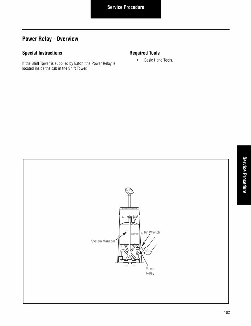
Power Relay - Overview
Special Instructions
If the Shift Tower is supplied by Eaton, the Power Relay is located inside the cab in the Shift Tower.
Required Tools• Basic Hand Tools.
7/16" Wrench
PowerRelay
System Manager
Service Procedure
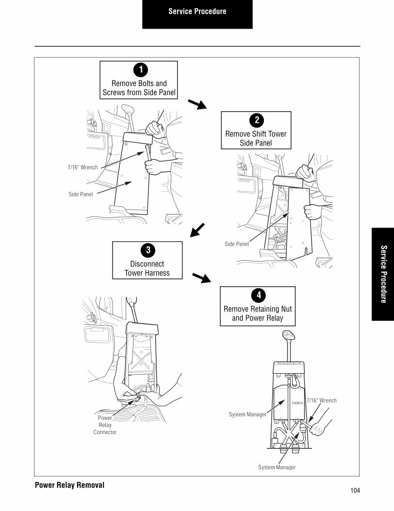
How to Remove the Power Relay
Procedure-
1. Using a 7/16" wrench, remove the two (2) Shift Lever mounting bolts from the driver's side of the Shift Tower.
2. Using a phillips-head screwdriver, remove the four (4) screws that secure the driver-side Shift Tower side panel.
3. Remove the Shift Tower side panel.
4. Disconnect the Tower Harness from the Power Relay.
5. Using a 7/16" wrench, remove the lower-right System Manager retaining nut that secures the Power Relay.
6. Remove the Power Relay.
103
Service ProcedureService Procedure
PowerRelay
Connector
3Disconnect
Tower Harness
Side Panel
Side Panel
7/16" Wrench
2Remove Shift Tower
Side Panel
1Remove Bolts and
Screws from Side Panel
4Remove Retaining Nut
and Power Relay
7/16" Wrench
System Manager
System Manager
104Power Relay Removal
Service Procedure
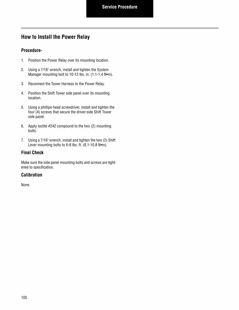
How to Install the Power Relay
Procedure-
1. Position the Power Relay over its mounting location.
2. Using a 7/16" wrench, install and tighten the System Manager mounting bolt to 10-12 lbs. in. (1.1-1.4 N•m).
3. Reconnect the Tower Harness to the Power Relay.
4. Position the Shift Tower side panel over its mounting location.
5. Using a phillips-head screwdriver, install and tighten the four (4) screws that secure the driver-side Shift Tower side panel.
6. Apply loctite #242 compound to the two (2) mounting bolts.
7. Using a 7/16" wrench, install and tighten the two (2) Shift Lever mounting bolts to 6-8 lbs. ft. (8.1-10.8 N•m).
Final Check
Make sure the side panel mounting bolts and screws are tight-ened to specification.
Calibration
None.
105

Service ProcedureService Procedure
Side Panel
3Install Shift Tower
Side Panel
PowerRelay
Connector
7/16" Wrench
System Manager
System Manager
2Reconnect
Tower Harness
1Install Power Relayand Retaining Nut
4Install and TightenBolts and Screws
Side Panel
7/16" Wrench
106Power Relay Installation

Service Procedure
Solo Heavy Duty Clutch - Install, Con’t
107

108
Service ProcedureService Procedure
System Manager - Overview
Special Instructions
None.
Required Tools• Basic Hand Tools.
SW
LOGI
C
SYSM
AN
COM
MSY
SMAN
SERV
ICE
VEHI
CLE
RELA
Y
TRAN
SMIS
SION
DCC
System Manager

Service Procedure
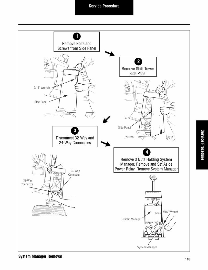
How to Remove the System Manager
Procedure-
1. Using a 7/16" wrench, remove the two (2) Shift Lever mounting bolts from the driver's side of the Shift Tower.
2. Using a phillips-head screwdriver, remove the four (4) screws that secure the driver-side Shift Tower side panel.
3. Remove the Shift Tower side panel.
4. Disconnect the System Manager 32-way connector.
5. Disconnect the System Manager 24-way connector.
6. Using a 7/16" wrench, remove the three (3) System Man-ager mounting nuts.
7. Temporarily disconnect and remove the Power Relay and set it aside.
8. Slide the System Manager down and out of the Shift Tower.
109
Service ProcedureService Procedure
32-Way Connector
24-Way Connector
3Disconnect 32-Way and
24-Way Connectors
Side Panel
Side Panel
7/16" Wrench
2Remove Shift Tower
Side Panel
1Remove Bolts and
Screws from Side Panel
4Remove 3 Nuts Holding SystemManager, Remove and Set Aside
Power Relay, Remove System Manager
7/16" Wrench
System Manager
System Manager
110System Manager Removal
Service Procedure
How to Install the System Manager
Procedure-
1. Slide the System Manager into the Shift Tower and posi-tion it on the three (3) mounting studs.
2. Install and finger tighten two (2) of the System Manager mounting nuts.
3. Reinstall the Power Relay in its original location and fin-ger tighten the System Manager/Power Relay mounting nut.
4. Using a 7/16" wrench, tighten the three (3) System Man-ager mounting nuts to 10-12 lbs. in. (1.1-1.4 N•m).
5. Reconnect the Tower Harness to the Power Relay.
6. Reconnect the System Manager 32-way connector.
7. Reconnect the System Manager 24-way connector.
8. Position the Shift Tower side panel over its mounting location.
9. Using a phillips-head screwdriver, install and tighten the four (4) screws that secure the driver-side Shift Tower side panel.
10. Apply loctite #242 compound to the two (2) mounting bolts.
11. Using a 7/16" wrench, install and tighten the two (2) Shift Lever mounting bolts to 6-8 lbs. ft. (8.1-10.8 N•m).
Final Check
Make sure the connectors are secure before installing the side panel.
Make sure the side panel mounting bolts and screws are tight-ened to specification.
Calibration
None.
111

Service ProcedureService Procedure
Side Panel
3Install Shift Tower
Side Panel
32-Way Connector
24-Way Connector
7/16" Wrench
System Manager
System Manager
2Reconnect Tower Harness to Power
Relay, 24-Way Connector and32-Way Connector
1Install System Manager
and Power Relay
3Tighten Bolts and
Screws on Side Panel
Side Panel
7/16" Wrench
112System Manager Installation

Service Procedure
Solo Heavy Duty Clutch - Install, Con’t
113

114
Service ProcedureService Procedure
Tower Harness - Overview
Special Instructions
None.
Required Tools• Basic Hand Tools.
SW
LOGI
C
SYSM
AN
COM
MSY
SMAN
SERV
ICE
VEHI
CLE
RELA
Y
TRAN
SMIS
SION
DCC
Tower Harness
Service Procedure
How to Remove the Tower Harness
Procedure-
1. Using a 7/16" wrench, remove the two (2) Shift Lever mounting bolts from the driver's side of the Shift Tower.
2. Using a phillips-head screwdriver, remove the four (4) screws that secure the driver-side Shift Tower side panel.
3. Remove the Shift Tower side panel.
4. Disconnect the 24-way connector and 3-way connector from the Shift Lever.
5. Disconnect the System Manager 32-way connector.
6. Disconnect the System Manager 24-way connector.
7. Disconnect the Tower Harness from the Power Relay.
8. Disconnect the two (2) Tower Harness connectors from the Tower Harness sockets beneath the vehicle floor-board.
9. Using a 1-11/16" wrench, remove the two (2) washers and jam nuts from the Tower Harness sockets.
Note: The jam nuts are located under the vehicle floor-board directly above the transmission.
10. Remove the Tower Harness from the Shift Tower.
115

Service ProcedureService Procedure
3Disconnect 24-Way and 3-WayConnectors from the Shift Lever
Side Panel
Side Panel
7/16" Wrench
2Remove Shift Tower
Side Panel
1Remove Bolts and Screws from
Tower Side Panel
4Disconnect 32-Way and 24-Way
Connectors from System manager
5Disconnect
Power Relay
32-Way Connector
24-Way Connector
Power Relay
5Tower
HarnessConnectors
Washer
Nut
1-11/16" Wrench
TransmissionHarness Connectors
6Disconnect and RemoveHarness from Floorboard
116Tower Harness Removal
Service Procedure
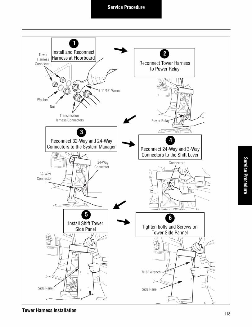
How to Install the Tower Harness
Procedure-
1. Slide the two (2) large Tower Harness sockets down through the vehicle floorboard.
Note: The connectors are individually keyed to match the appropriate Tower Harness sockets.
2. Using a 1-11/16" socket wrench, install and tighten the washers and jam nuts to 260-280 lbs. in. (29.4-31.6 N•m).
3. Reconnect the two (2) Tower Harness connectors to the sockets underneath the vehicle floorboard.
4. Route the new Tower Harness from the floorboard, up into the Shift Tower assembly.
5. Reconnect the Tower Harness to the Power Relay.
6. Reconnect the System Manager 32-way connector.
7. Reconnect the System Manager 24-way connector.
8. Reconnect the 24-way connector and 3-way connector to the Shift Lever.
9. Position the Shift Tower side panel over its mounting location.
10. Using a phillips-head screwdriver, install and tighten the four (4) screws that secure the driver-side Shift Tower side panel.
11. Apply loctite #242 compound to the two (2) mounting bolts.
12. Using a 7/16" wrench, install and tighten the two (2) Shift Lever mounting bolts to 6-8 lbs. ft. (8.1-10.8 N•m).
Final Check
Make sure the connectors are secure before installing the side panel.
Make sure the side panel mounting bolts and screws are tight-ened to specification.
Calibration
None.
117
Service ProcedureService Procedure
32-Way Connector
24-Way Connector
3Reconnect 32-Way and 24-Way
Connectors to the System Manager
Power Relay
5
TowerHarness
Connectors
Washer
Nut
1-11/16" Wrench
TransmissionHarness Connectors
2
Reconnect Tower Harnessto Power Relay
1Install and ReconnectHarness at Floorboard
4Reconnect 24-Way and 3-WayConnectors to the Shift Lever
Connectors
35Install Shift Tower
Side Panel
Side Panel Side Panel
7/16" Wrench
6Tighten bolts and Screws on
Tower Side Pannel
118Tower Harness Installation

Service Procedure
Solo Heavy Duty Clutch - Install, Con’t
119

120
Service ProcedureService Procedure
Gear Display - Overview
Special Instructions
The exact location varies depending on vehicle manufacturer.
Required Tools• Basic Hand Tools.
2
Service Procedure
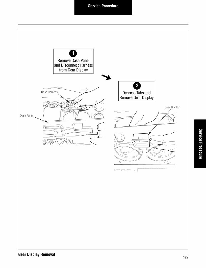
How to Remove the Gear Display
Procedure-
1. Follow the recommended OEM procedure to remove the dash panel that holds the Gear Display unit.
2. Disconnect the Dash Harness from the Gear Display unit.
3. Use a small flat bladed screwdriver to depress the tabs that hold the Gear Display in the dash. Then remove the Gear Display from the dash panel.
121
Service ProcedureService Procedure
Dash Panel
Dash Harness
Gear Display
2Depress Tabs and
Remove Gear Display
1Remove Dash Panel
and Disconnect Harnessfrom Gear Display
122Gear Display Removal
Service Procedure
How to Install the Gear Display
Procedure-
1. Install the Gear Display unit in the dash panel.
2. Reconnect the Dash Harness to the Gear Display unit.
3. Follow the recommended OEM procedure to install the dash panel that holds the Gear Display unit.
Final Check
Make sure the OEM Dash Harness is properly connected.
Make sure the dash panel is properly installed.
Calibration
None.
123

Service ProcedureService Procedure
Dash Panel
Dash Harness
Gear Display2
Reconnect Dash Harness and Install Dash Panel
1Install Gear
Display
124Gear Display Installation
SUSM-000403/04 PDFPrinted in USA
The Roadranger® System is an unbeatable combination of the bestproducts from Eaton and Dana -- partnering to provide you the mostadvanced, most trouble-free drivetrain in the industry. And it'sbacked by the Roadrangers -- the most experienced, most expert,most accessible drivetrain consultants in the business. Visit our web site at www.roadranger.com. For spec'ing or service assistance,call 1-800-826-HELP (4357) 24 hours a day, 7 days a week,(Mexico: 001-800-826-HELP (4357)) for more time on the road.
Copyright Eaton and Dana Corporation, 2002. EATON AND DANA CORPORATIONhereby grants its customers, vendors, or distributors permission to freely copy,reproduce and/or distribute this document in printed format. THIS INFORMATION IS NOT INTENDED FOR SALE OR RE-SALE, AND THIS NOTICE MUST REMAIN ON ALL COPIES.