Easy-to-perform and cost-effective fabrication of ...
18
Easy-to-perform and cost-effective fabrication of continuous-flow reactors and their application for nanomaterials synthesis Domenico Andrea Cristaldi a,c , Fatih Yanar a , Ali Mosayyebi a , Pablo García-Manrique b , Eugen Stulz c, *, Dario Carugo d, *, Xunli Zhang a, * a Bioengineering Group, Faculty of Engineering and the Environment, University of Southampton, UK b Departments of Physical and Analytical Chemistry, and Chemical Engineering and Environmental Technology, University of Oviedo, Spain. c School of Chemistry & Institute for Life Sciences, University of Southampton, Highfield, Southampton, UK. d Mechatronics and Bioengineering Science Research Groups, Faculty of Engineering and the Environment, Institute for Life Sciences (IfLS), University of Southampton, UK. Keywords: 3D printing, lab-on-a-chip, soft lithography, nanoparticles, liposomes, continuous-flow reactors.
Transcript of Easy-to-perform and cost-effective fabrication of ...

Easy-to-perform and cost-effective
fabrication of continuous-flow reactors
and their application for nanomaterials
synthesis
Domenico Andrea Cristaldi a,c, Fatih Yanar a, Ali Mosayyebi a, Pablo García-Manrique b,
Eugen Stulz c,*, Dario Carugo d,*, Xunli Zhang a,*
a Bioengineering Group, Faculty of Engineering and the Environment, University of Southampton, UK
b Departments of Physical and Analytical Chemistry, and Chemical Engineering and Environmental Technology,
University of Oviedo, Spain.
c School of Chemistry & Institute for Life Sciences, University of Southampton, Highfield, Southampton, UK.
d Mechatronics and Bioengineering Science Research Groups, Faculty of Engineering and the Environment,
Institute for Life Sciences (IfLS), University of Southampton, UK.
Keywords: 3D printing, lab-on-a-chip, soft lithography, nanoparticles, liposomes, continuous-flow reactors.

Abstract
The translation of continuous-flow microreactor technology to the industrial environment has
been limited by cost and complexity of the fabrication procedures, and the requirement for
specialised infrastructure. In the present study, we have developed a significantly cost-effective
and easy-to-perform fabrication method for the generation of optically transparent, continuous-
flow reactors. The method combines 3D printing of master moulds with sealing of the PDMS
channels’ replica using a pressure-sensitive adhesive tape. Morphological characterisation of
the 3D printed moulds was performed, and reactors were fabricated with an approximately
square-shaped cross-section of 1 mm2. Notably, they were tested for operation over a wide
range of volumetric flow rates, up to 20 ml/min. Moreover, the fabrication time (i.e., from
design to the finished product) was <1 day, at an average material cost of ~£5. The flow reactors
have been applied to the production of both inorganic nanoparticles (silver nanospheres) and
organic vesicular systems (liposomes), and their performance compared with reactors produced
using more expensive and laborious fabrication methods. Numerical simulations were
performed to characterise the transport of fluids and chemical species within the devices. The
developed fabrication method is suitable for scaled-up fabrication of continuous-flow reactors,
with potential for application in biotechnology and nanomedicine.

Introduction
Photolithography has been widely used to manufacture continuous-flow reactors at high spatial
resolution, in terms of both size and shape of the channels [1]. However, this process involves
numerous steps and generally requires specialised cleanroom facilities, and expensive
materials and instrumentation. Additionally, the whole process (i.e., from the design of the
device architecture to the end product) is highly time-consuming. The combination of these
factors has hindered the widespread adoption of this technology by industries and researchers,
particularly in the non-specialised or less resourced laboratories.
In the last decade, efforts have been made to develop more cost-effective and user friendly
manufacturing approaches [2]. For instance, the micromilling-replica moulding (μMi-REM)
technique recently developed by Carugo et al. [3] involves the fabrication of positive epoxy
masters obtained from negative micromilled moulds (made of polymethyl methacrylate,
PMMA). This procedure does not require the fabrication of photomasks via photolithography,
which is typically performed in a cleanroom environment. The method however requires the
use of micromilling machines, as well as oxygen plasma bonding for the sealing of the
polydimethylsiloxane (PDMS) channels onto a glass layer. Alternatively, positive moulds can
be fabricated in a single step using high-resolution 3D printing (with channel width down to
50 m), as demonstrated by Comina et al. [4] Similarly, three-dimensional (3D) PDMS
microfluidic reactors can be fabricated via UV-activated 3D printing, as described by Chan et
al [5]. Although 3D printing of resin moulds may be less complex to perform compared to
μMi-REM, it requires specific treatments of the moulds prior to PDMS casting, due to the
inhibition effect of the resin on the PDMS cross-linker [6,4]. In addition, both methods rely on
the use of oxygen plasma during the bonding process. Alternatively, microfluidic devices could
be entirely 3D printed, as demonstrated by Kitson et al. [7]. This method is cost-effective and
easy-to-perform; however, devices are not optically transparent, thus limiting the ability to
optically monitor flow and mixing processes. The optical transparency of 3D printed channels
was recently improved by Gaal et al. [8], using a custom built 3D printer to create polylactic
acid/polydimethylsiloxane (PLA/PDMS) architectures. However, careful adjustments of the
3D printer settings were needed during the fabrication process, and the cross-section of the
produced channels differed significantly from the original computer-aided design (CAD).
Developments have also been made in terms of the microchannel dimensions obtainable using
3D printing, with recent studies researching novel resin formulations for stereolithgraphy (SL)

and 3D printing with Digital Light Processing (DLP) [9]. With this technique, Gong et al.
demonstrated the generation of remarkably small microchannels (i.e., down to 18 × 20 m)
[10]. Significant efforts have also been devoted to the development of simple bonding
techniques for microfluidic architectures. For example, Serra et al. [11] recently demonstrated
the use of a commercially available sealing tape (Thermalseal RTSTM) for bonding of various
substrates. The PDMS channel architectures in this study were fabricated from micromilled
brass masters.
In the present study, we developed a fast, cost-effective and facile manufacturing process to
fabricate optically transparent flow reactors, with milli- or sub-millimetre scale flow channels
(i.e., with 0.5-1.0 mm channel width). A combination of techniques was employed including
3D printing of positive moulds followed by PDMS casting (3D printed mould casting, 3DPM-
C), and direct sealing of the PDMS layer using a pressure-sensitive adhesive tape. The 3D
printed moulds were characterized in terms of surface roughness and cross-sectional shape, and
the reactors were tested over a wide range of operational conditions. To demonstrate the
usability of the developed fabrication technique, reactors were applied to the production of
silver nanospheres (SNSs) and liposomes, as examples of inorganic and organic synthesis,
respectively.
Silver nanospheres (SNSs) have been employed in many research fields ranging from
photocatalysis [12] to optoelectronics [13], but also for biological applications due to their
antibacterial properties [14]. SNSs synthesis typically needs a carefully balanced
stoichiometry, in order to obtain the desired particle size and/or shape [15]. Recently, Barber
et al. demonstrated a coaxial glass reactor for continuous-flow production of SNSs [16], with
superior control over the fluidic environment and the properties of the produced SNSs, when
compared to bulk methods. Liposomes, which are spherical vesicles comprising an aqueous
core surrounded by a lipid bilayer, are employed as vehicles for transporting and administering
pharmaceutical actives [17]. Production of liposomes via solvent exchange mechanism in
continuous-flow reactors has emerged as a promising technique, offering an higher degree of
control over the physical and dimensional properties of the end product, compared to batch
methods.
In this study, we demonstrate continuous-flow production of both types of nanoscale particles
using cost-effective and easy-to-operate reactors.

Materials and Methods
Design, fabrication and morphological characterization of flow reactors
Fabrication of the 3D printed mould casting (3DPM-C) channels is illustrated in Scheme 1.
Solidworks® CAD 2016 software was used for designing the master mould. The flow reactor
architecture has two semi-circular inlet channels of 0.50 mm × 1.00 mm (width × height) and
1.50 mm radius. Inlets converge in to a straight channel of 1.00 mm × 1.00 mm × 60.00 mm
(width × height × length). The channel architecture was positioned at the bottom surface of a
box structure having a 7.00 mm high edge, which acted as a container for uncured PDMS (see
Step 1 in Scheme 1). The Ultimaker 2+ 3D printer, loaded with PLA filaments, was employed
as a representative fused deposition modelling (FDM) tool for the production of the master
moulds. The following printing settings were adopted: bottom/top thickness = 0.5 mm, fill
density = 100%, print speed = 50 mm/s, and nozzle size = 0.4 mm. PDMS replicas were
prepared by pouring a 10.2/0.8 (w/w) ratio of degassed PDMS precursor and curing agent
mixture (Sylgard® 184, Dow Corning Corporation, Michigan, USA) over the mould (Scheme
1, Step 2). Degassing was carried out by centrifugation at 3000 rpm for 15 min, using the
Eppendorf Centrifuge 5804 and Corning CentristarTM tubes (50 ml). After pouring, the liquid
PDMS was left at room temperature for 4 h and any formed gas bubble removed using a sharp
tool (every 1 hour). This step could be significantly accelerated by placing the mould under
vacuum. PDMS curing was performed in the oven at 40 °C overnight. The cured PDMS replica
channel was peeled off from the master mould, and a 1.5 mm diameter biopsy punch with
plunger (Miltex®, Fischer Scientific, UK) was used for creating inlets/outlets. Sealing of the
PDMS layer was performed on ThermalSeal RT™ tape purchased from Excel Scientific (USA)
(Scheme 1, Step 3). To characterise the morphology of the 3D printed moulds, a non-contact
Alicona Infinite Focus 3D optical profilometer was employed (5× magnification lens, vertical
resolution: 410 nm, lateral resolution: 6.59 m). In order to evaluate the method’s repeatability,
three identical devices were printed and two-dimensional (2D) images (at 2.5× magnification)
were acquired to measure (i) the width of the mixing channel at five equidistant locations along
the channel (separation distance between measurements = 2 mm) starting from the junction,
and (ii) the radius of curvature of both inlet channels. Measurements were performed using
Image-J software (NIH, USA).

The manufacturing of μMi-REM devices was performed following a protocol previously
reported in the literature [3]. The PVA-TePla 300 plasma cleaner was employed to assist the
bonding of the PDMS layer with a 50 × 70 mm glass sheet (Corning® microscope slides, Sigma
Aldrich, Gillingham, UK).
The two fabrication methods employed in this study are herein defined as 3DPM-C/Tape and
µMi-REM*Glass, where ‘/’ and ‘*’ indicate adhesive tape and plasma bonding procedures,
respectively.
Scheme 1: Graphical representation of the manufacturing steps for the 3DPM-C/Tape reactor: 1) Low-cost 3D
printing of the positive mould; 2) PDMS casting; and 3) sealing of the cured PDMS layer onto adhesive tape.
Synthesis of inorganic and organic nanoparticles
The same experimental set-up was used for the production of both silver nanospheres and
liposomes. Syringe pumps (AL-1010) were purchased from World Precision Instruments (UK).
Luer Lock syringes (20ml) (BD Plastipak) were purchased from BD (Becton, Dickinson and
Company, UK). Polytetrafluoroethylene (PTFE) tubing and connectors (Cole-Palmer, UK)
were employed for interfacing the device inlets and outlet with syringes and collection vials,
respectively. The length of the tube from the outlet to the collection vial was 26.70 cm.
Silver nanoparticles were synthetized using silver nitrate 99.9999% (AgNO3), tri sodium citrate
dihydrate ≥ 99.0% (TSCD), polyvinylpyrrolidone (PVP), and sodium borohydride 99%
(NaBH4), which were purchased from Sigma Aldrich UK (Gillingham, UK). Propan-2-ol (or
isopropyl alcohol, IPA) laboratory reagent grade was purchased from Fisher Chemical (UK).
Milli-Q water was collected using the Q-Gard purification filter, connected to the Milli-Q
Gradient A10 system (Merck Millipore, USA).

Scheme 2 shows the experimental set-up employed for the synthesis of both silver
nanoparticles and liposomes. Syringes were spatially arranged in a way that allowed
performing the same experiment for both 3DPM-C/Tape and Mi-REM*Glass devices, by
simply changing the reactor.
For SNSs production, a 20 ml syringe was primed with a Milli-Q water solution containing
AgNO3 (1.02 mM), TSCD (15.02 mM), and PVP (0.45 M). The second syringe was primed
with 15 ml of an IPA/Milli-Q solution (9:1 v/v) of NaBH4 (5.28 mM). The total flow rate (TFR
= FRA + FRB) was kept at the constant value of 1 ml/min, whereas the flow rate ratio (FRR =
FRA / FRB) was varied (5, 7, 9 and 11). Each sample was separately collected in a 1.5 ml
Eppendorf tube, and 1.5 ml were collected in a waste vial in between each experimental run.
In order to evaluate the robustness of the reaction, experiments were repeated in triplicate at
selected TFR and FRR values.
For the synthesis of liposomes, Phospholipon® 90G (lipids) and purified phosphatidylcholine
from soybean lecithin, were kindly provided by Lipoid GmbH (Germany). Pure ethanol
(99.9%) was purchased from Sigma-Aldrich Company Ltd. (UK).
A 100 mM lipid solution in ethanol was prepared, and the lipid concentration selected to
produce liposomes of a clinically relevant size and mass [18-20]. Milli-Q water was injected
into one inlet (Syringe A) and ethanol-containing lipids was injected into a second inlet
(Syringe B), for each reactor (Scheme 2).
Experiments were carried out maintaining a constant FRR of 25, at varying TFRs of 1, 3 and 6
ml/min to demonstrate devices’ usability for producing liposomes at high-throughput. Three
samples were collected, at each TFR and for each device tested.
Scheme 2: Schematic of the experimental set-up and list of chemicals injected through syringes A and B for the
production of SNSs and liposomes, respectively.
Characterisation of nanoparticles

The UV-Visible characterization of silver nanospheres (SNSs) was carried out using a Varian
Cary300Bio UV-Visible Spectrophotometer. All measurements were performed in the 200-800
nm range, with an increment step of 0.5 nm. 1 ml of each sample was collected from the flow
reactors, and diluted to 3 ml with Milli-Q water into a quartz cuvette for the spectrophotometric
characterization. The baseline was subtracted from each experimental condition (i.e.,
considering the specific Milli-Q/IPA volume ratio).
Moreover, transmission electron microscopy (TEM) characterization of SNSs was performed.
Images were acquired using the TEM Hitachi HT7700. Silver nanoparticles were prepared by
drop-casting of the colloidal synthesis solution (5 L), on carbon and Formvar coated Cu/Pd
200 mesh grids, and left to dry under atmospheric conditions at room temperature.
A dynamic light scattering (DLS) technique was instead used to measure the mean diameter
(z-average), the polydispersity index (PDI), and zeta potential of all liposomal formulations,
produced with both 3DPM-C/Tape and µMi-REM*Glass reactors. Liposome dimensional
stability was assessed by measuring the mean diameter of samples stored at both 4°C and 25°C,
every 5 days for a total 30 days. All measurements were performed using the Zetasizer Nano
ZS Malvern, UK.
Results and Discussion
Characterisation of the 3D printed moulds and PDMS channels
The morphology and roughness of the flat base of the 3D printed master are important
characteristics affecting spatial uniformity and durability of the sealing. From the
morphological examination, diagonal grooves can be observed due to the oblique motion of
the nozzle in the x-y plane during printing (see Figure 1a). The average roughness (Ra) value
of the master mould is 6.56 m (Figure 1a), and a maximum peak-to-valley (Rz) value of 85.13
m is detected in proximity to the diagonal features over the base surface (representative cross
sectional profiles are shown in Figure SI-1a). Notably, we observed that grooves could promote
fluid leakage at flow rates greater than 5 ml/min.
In order to overcome this limitation, the PDMS mixture (monomer/curing agent) was prepared
using 8% curing agent (instead of the commonly used 10% by mass), to reduce the PDMS
stiffness. Notably, a softer PDMS could be deformed more easily by applying external pressure
during sealing. Manual compression using a plastic spatula was initially performed (at an

estimated pressure of 1 bar), followed by compression at ~0.5 bar for 1 hr. In this way, no
leakages were observed even at a total flow rate of 20 ml/min (see supporting information
video, at https://youtu.be/EpmnLZDXtBo), confirming the effectiveness of the sealing
procedure for continuous-flow synthesis at high-throughput.
Figure 1: Morphology and cross-sectional shape of the 3D printed moulds. a) Morphological characterisation of
the 3D printed base, including average roughness (Ra) and maximum peak-to-valley value (Rz). b) Cross section
of a representative channel design of 0.60 × 0.80 mm (width × height), obtained from optical profilometry.
Accurate reproduction of the designed (i.e., nominal) channel size and shape should ideally be
achieved by the 3D printing process. In this respect, the high resolution (HR) resin 3D printer
(Object Connex 350) was tested against the Ultimaker 2+ by printing channels of different
cross-sectional dimension, as illustrated in Figure SI-1b. The HR 3D printer was able to create
smaller and smoother channels; however, reproduction of the cross sectional shape was less
accurate, even for the relatively large channel dimension of 1.00 × 1.00 mm (see cross section
in Figure SI-1c obtained from profilometry). Thus, the Ultimaker 2+ was selected to generate
the master moulds in the remaining experiments.
Two additional test channels were printed having different size but the same aspect ratio of
1.33, using the Ultimaker 2+. The mean experimental values obtained with the optical
profilometer (representative test Channel 1 in Figure 1b) are compared with the nominal
dimensions of both channels in Table 1. The channel height is accurately reproduced, whereas
the width is affected by a 0.09 mm difference for both test channels 1 and 2 (a 3D cross section
of test Channel 2 is shown in Figure SI-1c). This is due to the orientation angle (90°) of the
side walls of the channels with respect to the light source of the profilometer. This effect is
clearly visible in Figure 1b in which the side walls of the channel are represented as the
projection of the edge of the channel roof towards the base, causing overestimation of the
measured width.

Table 1: Size comparison between the CAD design and the 3D printed channels.
Design-Morphology
Comparisons
Width × Height (mm)
Test Channel 1
Width × Height (mm)
Test Channel 2
CAD Design
0.60 × 0.80
0.80 × 1.33
3D Printed mould profile
(mean values)
0.69 × 0.80
0.89 × 1.33
Nonetheless, in order to assess repeatability of the reactor’s fabrication method, three replicas
of the 3D printed moulds were manufactured using the Ultimaker 2+ (Figure 2). The width of
the mixing channel (measured at five separate and equidistant locations along the channel) and
the radius of curvature of the inlet channels were measured, and results are plotted in Figure 2a
and 2b respectively. Insets illustrate the positions at which measurements were taken.
Figure 2: a) Width of the mixing channel at 2, 4, 6, 8, and 10 mm from the junction between inlets, for three
different 3D printed moulds. An image of a representative channel (at 2.5× magnification) showing the
measurement lines (red lines) is reported in the inset. b) Radius of curvature of both right (R) and left (L) inlet
channels, for three different 3D printed moulds. A graphical representation of the measurement method is
reported in the inset, for the right inlet channel.
The width of the mixing channel is comparable between the three different moulds, as
illustrated in Figure 2a. The maximum difference is at 6 mm from the junction, between mould

n.1 and n.3, and is equal to 0.0011 mm only. All moulds had a slightly larger channel width in
proximity to the junction, which gradually reduced along the channel and reached a plateau
value at about 8-10 mm from the junction (see Figure 2a). The radius of curvature of the inlet
channels was also very comparable between different moulds (mean value = 1.770 ± 0.012
mm), and only slightly differed from the nominal value of 1.75 mm (see Figure 2b).
Synthesis of silver nanospheres and liposomes via 3DPM-C/Tape & μMi-REM*Glass reactors.
Nanoparticle synthesis via 3DPM-C/Tape reactor was performed in parallel with the already
established μMi-REM*Glass technique. In order to compare the performance of the two
fabrication methods, the physical properties of the produced nanomaterials were measured and
evaluated at varying fluid dynamic boundary conditions.
Synthesis of silver nanospheres.
Silver nanospheres (SNSs) were synthetized using the chemical reduction method [15], which
was adapted for usage in a continuous-flow reactor. Specifically, NaBH4 solution was prepared
initially by dissolving the solid in 1.5 ml of Milli-Q water, followed by dilution to 15 ml with
IPA. The use of IPA was to minimise the generation of H2, produced from the degradation of
NaBH4 in water [21]. This drastically reduces the formation of gas bubbles within the channels,
which may significantly alter the flow field or cause clogging. This effect may however be less
problematic in millimetre-scale channels. An alternative approach may involve the generation
of a strong basic condition (NaOH, 14 M) in water, as described by Barber et al. [16]. However,
with the protocol described in this study, we were able to produce SNSs at all FRRs
investigated, obtaining the maximum absorbance (Amax) of 2.9 ± 0.2 nm after 1:3 dilution with
Milli-Q water. Nevertheless, the stoichiometry played a critical role in SNSs synthesis, and
although the numerical results (see Figure SI-2b) show a marginal increase in mixing efficiency
at FRR = 11, the SNSs production performance was more effective at FRR = 7.
Figure 3a reports the UV-vis spectra of SNSs prepared using the 3DPM-C/Tape and the Mi-
REM*Glass reactors, applying the same operational conditions in both devices (TFR = 1
ml/min; FRR = 7). In order to assess the reproducibility of the reaction, samples were produced
in triplicate under the same conditions for both devices.
The typical absorption spectra, due to SNSs surface plasmon resonance (SPR) [22], are
observed. Notably, the SNSs spectra obtained using the two different fabrication methods are
almost overlapping across the whole wavelength spectrum. The mean value of maximum

absorbance (Amax) is equal to 3.252 ± 0.050 and 3.236 ± 0.068 for the Tape and Glass reactors,
respectively (see Figure 3a and inset). More importantly, in both types of reactor the maximum
absorption value of 398.0 nm is obtained, further indicating a comparable performance between
them. The absorbance value is also related to the particle size [23], which ranged from 10 to
20 nm as shown in the TEM images (Figure 3b).
Figure 3: a) UV-vis characterization of SNSs prepared using the 3DPM-C/Tape (black) and the Mi-REM*Glass
(red) reactors. Spectra are shown as the mean of triplicate samples prepared using both types of reactor, at the
same operating conditions (TFR = 1 ml/min; FRR = 7) (individual spectra are shown in the inset). b)
Representative TEM image of the SNSs prepared with the 3DPM-C/Tape (TFR = 1 ml/min; FRR = 7); with a
magnified view shown in the inset.
Synthesis of liposomes.
Having demonstrated that flow reactors fabricated with different methods have comparable
performance when employed to produce silver nanoparticles, they were also tested for
continuous-flow synthesis of liposomes. Devices were operated at total flow rates which were
significantly higher than those typically used in microfluidic reactors [20], to demonstrate their
potential utility for scaled-up synthesis.
Figure 4 shows the size (z-average) and polydispersity index (PDI) of liposomes produced at
varying TFR values (1, 3, 6 ml/min) and a fixed FRR of 25. A representative intensity-based
liposome size distribution (at TFR = 1 ml/min and FRR = 25) is also shown in Figure SI-3a,
for the µMi-REM*Glass reactor. Notably, liposome size and dispersity are not significantly
different across different devices, for all the hydrodynamic conditions investigated. For
instance, liposomes produced with the 3DPM-C/Tape and µMi-REM*Glass reactors at TFR =
1 ml/min and FRR = 25, have a diameter of 188.61 ± 1.62 nm and 191.37 ± 3.19 nm,
respectively. Moreover, by increasing the TFR from 1 to 6 ml/min caused only a slight increase
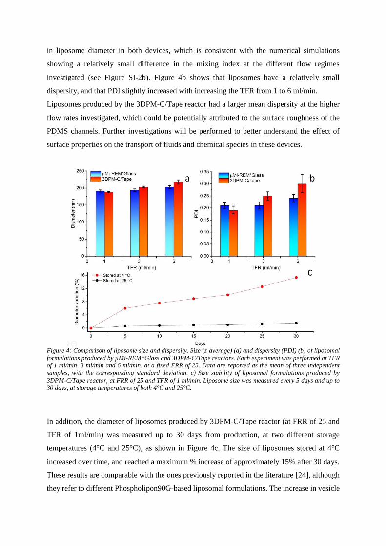
in liposome diameter in both devices, which is consistent with the numerical simulations
showing a relatively small difference in the mixing index at the different flow regimes
investigated (see Figure SI-2b). Figure 4b shows that liposomes have a relatively small
dispersity, and that PDI slightly increased with increasing the TFR from 1 to 6 ml/min.
Liposomes produced by the 3DPM-C/Tape reactor had a larger mean dispersity at the higher
flow rates investigated, which could be potentially attributed to the surface roughness of the
PDMS channels. Further investigations will be performed to better understand the effect of
surface properties on the transport of fluids and chemical species in these devices.
Figure 4: Comparison of liposome size and dispersity. Size (z-average) (a) and dispersity (PDI) (b) of liposomal
formulations produced by µMi-REM*Glass and 3DPM-C/Tape reactors. Each experiment was performed at TFR
of 1 ml/min, 3 ml/min and 6 ml/min, at a fixed FRR of 25. Data are reported as the mean of three independent
samples, with the corresponding standard deviation. c) Size stability of liposomal formulations produced by
3DPM-C/Tape reactor, at FRR of 25 and TFR of 1 ml/min. Liposome size was measured every 5 days and up to
30 days, at storage temperatures of both 4°C and 25°C.
In addition, the diameter of liposomes produced by 3DPM-C/Tape reactor (at FRR of 25 and
TFR of 1ml/min) was measured up to 30 days from production, at two different storage
temperatures (4°C and 25°C), as shown in Figure 4c. The size of liposomes stored at 4°C
increased over time, and reached a maximum % increase of approximately 15% after 30 days.
These results are comparable with the ones previously reported in the literature [24], although
they refer to different Phospholipon90G-based liposomal formulations. The increase in vesicle
diameter could be attributed to sterical hindrance of bilayer stability [25] or aggregation, which
may result in liposome coalescence [26]. Conversely, the size of liposomes stored at 25°C was
almost unchanged over time. Moreover, the zeta potential of liposomes produced using the
3DPM-C/Tape rector (at FRR of 25 and TFR of 1 ml/min) was -15.06 mV, which is coherent
with the literature [27].
Conclusions
We have developed an easy-to-perform and cost-effective method for the fabrication of PDMS
based continuous-flow reactors, through 3D printed mould casting (3DPM-C). In this method,
the positive mould was “printed” using a desktop 3D printer, followed by PDMS casting to
produce replica channels of millimetre or sub-millimetre width and height. Channels on the
PDMS replica were then sealed using a commercially available pressure-sensitive adhesive
tape. It was also demonstrated that the whole fabrication process can be completed within 24
h from the CAD design of the channel architecture, at an average cost of £5 per reactor. Simple
modifications to the conventional PDMS curing process were also implemented, in order to
overcome limitations associated with the use of a relatively low-cost 3D printer. The fabricated
reactors were further applied to the production of both inorganic nanoparticles (silver
nanospheres) and organic vesicular systems (liposomes). They exhibited comparable
performance to reactors fabricated using more laborious and expensive fabrication methods.
The manufacturing technique presented in this study is therefore potentially suitable for
scaling-up, as devices can be fabricated at low-cost, and without resorting to sophisticated
instrumentation and time-consuming multistep procedures. Moreover, devices produced with
this technique can be operated at relatively high total flow rates (>20 ml/min), which is a
desirable characteristic for application in continuous-flow chemical synthesis.

Glossary
3DPM-C/Tape 3D printed mould casting bonded on tape (the symbol “ / ” is used for the
simple adhesion on tape)
AgNO3 Silver nitrate
Amax Maximum Absorbance
CFD Computational Fluid Dynamics
DLP Digital Light Processing
DLS Dynamic Light Scattering,
FRR Flow Rate Ratio
HR High resolution
IPA Propan-2-ol or isopropyl alcohol
ml/min Milliliter per minute
NaBH4 Sodium borohydride
PDI Polydispersity Index,
Indication of the width of the overall distribution
PDMS Polydimethylsiloxane
Phospholipon®
90G
Lipids, Purified phosphatidylcholine from soybean lecithin, 3,4-dihydro-
2,5,7,8-tetramethyl-2-4,8,12-trimethyltridecyl-2Hbenzopyran-6-ol
PLA Polylactic acid
PTFE Polytetrafluoroethylene
PVP Polyvinylpyrrolidone
Ra Average roughness
Rz Maximum peak-to-valley value (refers to the Z axes)
SNSs Silver nanospheres
SPR Surface plasmon resonance
TEM Transmission Electron Microscopy
TFR Total Flow Rate
TSCD Tri sodium citrate dihydrate
z-average Average diameter or radius, intensity-based overall average size
μMi-REM Micromilling-replica moulding technique μmi-REM
μMi-REM*Glass Micromilled replica moulding bonded on glass by oxygen plasma (the
symbol “ * ” refers to the oxygen plasma treatment)
Acknowledgments
Authors would like to thank the University of Southampton for supporting the research through
a PhD studentship.
Appendices
See supporting information.

Figure Captions
Scheme 1: Graphical representation of the manufacturing steps for the 3DPM-C/Tape reactor:
1) Low-cost 3D printing of the positive mould; 2) PDMS casting; and 3) sealing of the cured
PDMS layer onto adhesive tape.
Scheme 2: Schematic of the experimental set-up and list of chemicals injected through syringes
A and B for the production of SNSs and liposomes, respectively.
Figure 1: Morphology and cross-sectional shape of the 3D printed moulds. a) Morphological
characterisation of the 3D printed base, including average roughness (Ra) and maximum peak-
to-valley value (Rz). b) Cross section of a representative channel design of 0.60 × 0.80 mm
(width × height), obtained from optical profilometry.
Table 1: Size comparison between the CAD design and the 3D printed channels.
Figure 2: a) Width of the mixing channel at 2, 4, 6, 8, and 10 mm from the junction between
inlets, for three different 3D printed moulds. An image of a representative channel (at 2.5×
magnification) showing the measurement lines (red lines) is reported in the inset. b) Radius of
curvature of both right (R) and left (L) inlet channels, for three different 3D printed moulds. A
graphical representation of the measurement method is reported in the inset, for the right inlet
channel.
Figure 3: Figure 3: a) UV-vis characterization of SNSs prepared using the 3DPM-C/Tape
(black) and the µMi-REM*Glass (red) reactors. Spectra are shown as the mean of triplicate
samples prepared using both types of reactor, at the same operating conditions (TFR = 1
ml/min; FRR = 7) (individual spectra are shown in the inset). b) Representative TEM image of
the SNSs prepared with the 3DPM-C/Tape (TFR = 1 ml/min; FRR = 7); with a magnified view
shown in the inset.
Figure 4: Comparison of liposome size and dispersity. Size (z-average) (a) and dispersity
(PDI) (b) of liposomal formulations produced by µMi-REM*Glass and 3DPM-C/Tape
reactors. Each experiment was performed at TFR of 1 ml/min, 3 ml/min and 6 ml/min, at a
fixed FRR of 25. Data are reported as the mean of three independent samples, with the
corresponding standard deviation. c) Size stability of liposomal formulations produced by
3DPM-C/Tape reactor, at FRR of 25 and TFR of 1 ml/min. Liposome size was measured every
5 days and up to 30 days, at storage temperatures of both 4°C and 25°C.

Bibliography
1. Dong, J., Liu, J., Kang, G., Xie, J. & Wang, Y. Pushing the resolution of
photolithography down to 15nm by surface plasmon interference. Sci. Rep. 4, 5618
(2014).
2. Hood, R. R., Wyderko, T. & DeVoe, D. L. Programmable digital droplet microfluidics
using a multibarrel capillary bundle. Sensors Actuators B Chem. 220, 992–999 (2015).
3. Carugo, D., Lee, J. Y., Pora, A., Browning, R. J., Capretto, L. et al. Facile and cost-
effective production of microscale PDMS architectures using a combined micromilling-
replica moulding ( μ Mi-REM ) technique. 1–10 (2016). doi:10.1007/s10544-015-0027-
x
4. Comina, G., Suska, A. & Filippini, D. PDMS lab-on-a-chip fabrication using 3D printed
templates. Lab Chip 14, 424–30 (2014).
5. Chan, H. N., Chen, Y., Shu, Y., Chen, Y., Tian, Q., & Wu, H. Direct, one-step molding
of 3D-printed structures for convenient fabrication of truly 3D PDMS microfluidic
chips. Microfluid. Nanofluidics 19, 9–18 (2015).
6. Hassan, S.-U., Nightingale, A. M. & Niu, X. Continuous measurement of enzymatic
kinetics in droplet flow for point-of-care monitoring. Analyst 141, 3266–73 (2016).
7. Kitson, P. J., Rosnes, M. H., Sans, V., Dragone, V. & Cronin, L. Configurable 3D-
Printed millifluidic and microfluidic ‘lab on a chip’ reactionware devices. Lab Chip 12,
3267 (2012).
8. Gaal, G., Mendesa, M., de Almeidab, T. P., Piazzettad, M. H.O., Gobbi, Â. L. et al.
Simplified fabrication of integrated microfluidic devices using fused deposition
modeling 3D printing. Sensors Actuators B Chem. 242, 35–40 (2017).
9. Gong, H., Beauchamp, M., Perry, S., Woolley, A. T. & Nordin, G. P. Optical approach
to resin formulation for 3D printed microfluidics. RSC Adv. 5, 3627–3637 (2015).
10. Gong, H., Bickham, B., Woolley, A. T. & Nordin, G. P. Custom 3D printer and resin
for 18 μm × 20 μm microfluidic flow channels. Lab Chip (2017).
doi:10.1039/C7LC00644F
11. Serra, M., Pereiro, I., Yamada, A., Viovy, J.-L., Descroix, S., & Ferraro, D. A simple
and low-cost chip bonding solution for high pressure, high temperature and biological
applications. Lab Chip 17, 629–634 (2017).
12. Navjot, Tovstolytkin, A. & Lotey, G. S. Plasmonic Enhanced Photocatalytic Activity of
Ag Nanospheres Decorated BiFeO3 Nanoparticles. Catal. Letters 147, 1640–1645
(2017).
13. Wang, L., Chen, R., Ren, Z.-F., Ge, C.-W., Liu, Z.-X. et al. Plasmonic silver nanosphere
enhanced ZnSe nanoribbon / Si heterojunction optoelectronic devices. Nanotechnology.
27, 215202 (2016).
14. Le Ouay, B. & Stellacci, F. Antibacterial activity of silver nanoparticles: A surface
science insight. Nano Today 10, 339–354 (2015).
15. Griffith, M., Udekwu, K. I., Gkotzis, S., Mah, T. & Alarcon, E. I. Silver Nanoparticle
Applications. Silver Nanoparticle Applications (2015). doi:10.1007/978-3-319-11262-6
16. Baber, R., Mazzei, L., Thanh, N. T. K. & Gavriilidis, A. Synthesis of silver nanoparticles
in a microfluidic coaxial flow reactor. RSC Adv. 5, 95585–95591 (2015).
17. Akbarzadeh, A., Rezaei-sadabady, R., Davaran, S., Joo, S. W. & Zarghami, N.
Liposome : classification , preparation , and applications. 1–9 (2013). doi:10.1186/1556-
276X-8-102
18. Swaay, D. van & deMello, A. Microfluidic methods for forming liposomes. Lab Chip
13, 752–767 (2013).

19. Jahn, A., Vreeland, W. N., Gaitan, M. & Locascio, L. E. Controlled Vesicle Self-
Assembly in Microfluidic Channels with Hydrodynamic Focusing. J. Am. Chem. Soc.
126, 2674–2675 (2004).
20. Carugo, D., Bottaro, E., Owen, J., Stride, E. & Nastruzzi, C. Liposome production by
microfluidics: potential and limiting factors. Sci. Rep. 6, 25876 (2016).
21. Carboni, M., Capretto, L., Carugo, D., Stulz, E. & Zhang, X. Microfluidics-based
continuous flow formation of triangular silver nanoprisms with tuneable surface
plasmon resonance. J. Mater. Chem. C 1, 7540 (2013).
22. Amendola, V., Bakr, O. M. & Stellacci, F. A study of the surface plasmon resonance of
silver nanoparticles by the discrete dipole approximation method: Effect of shape, size,
structure, and assembly. Plasmonics 5, 85–97 (2010).
23. Paramelle, D., Sadovoy, A., Gorelik, S., Free, P., Hobley, J., & Fernig D. G. A rapid
method to estimate the concentration of citrate capped silver nanoparticles from UV-
visible light spectra. Analyst 139, 4855–61 (2014).
24. Briuglia, M.-L., Rotella, C., McFarlane, A. & Lamprou, D. A. Influence of cholesterol
on liposome stability and on in vitro drug release. Drug Deliv. Transl. Res. 5, 231–242
(2015).
25. Thoma, K. & Jocham, U. E. in Liposome Dermatics 150–166 (Springer Berlin
Heidelberg, 1992). doi:10.1007/978-3-642-48391-2_15
26. Takeuchi, H., Yamamoto, H., Toyoda, T., Toyobuku, H., Hino, T., & Kawashima, Y.
Physical stability of size controlled small unilameller liposomes coated with a modified
polyvinyl alcohol. Int. J. Pharm. 164, 103–111 (1998).
27. Mahmud, M., Piwoni, A., Filiczak, N., Janicka, M. & Gubernator, J. Long-Circulating
Curcumin-Loaded Liposome Formulations with High Incorporation Efficiency,
Stability and Anticancer Activity towards Pancreatic Adenocarcinoma Cell Lines In
Vitro. PLoS One 11, e0167787 (2016).