
Disposal of Septage in Municipal Sewage Systems ---s. 281 ...

Last Update: 06/21/2021
2270 TRUMBLE ROAD
PERRIS, CALIFORNIA 92570
(951) 928-3777
EASTERN MUNICIPAL WATER DISTRICT
SMALL SEWAGE LIFT STATION GUIDELINES,
STANDARD DRAWINGS, AND SPECIFICATIONS
Prepared by
(951) 684-6900
Office: 3602 University Ave, Riverside, CA 92501
Mail/Ship: 3890 Orange St #1509, Riverside, CA 92502

[PAGE LEFT INTENTIONALLY BLANK]

TABLE OF CONTENTS

[PAGE LEFT INTENTIONALLY BLANK]
Last Update: 06/21/2021
i
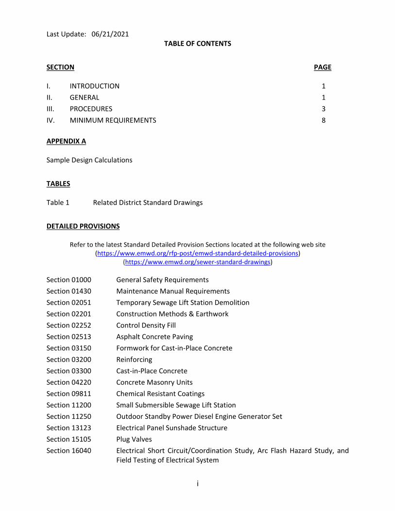
TABLE OF CONTENTS
SECTION PAGE
I. INTRODUCTION 1
II. GENERAL 1
III. PROCEDURES 3
IV. MINIMUM REQUIREMENTS 8
APPENDIX A
Sample Design Calculations
TABLES
Table 1 Related District Standard Drawings
DETAILED PROVISIONS
Refer to the latest Standard Detailed Provision Sections located at the following web site
(https://www.emwd.org/rfp-post/emwd-standard-detailed-provisions)
(https://www.emwd.org/sewer-standard-drawings)
Section 01000 General Safety Requirements
Section 01430 Maintenance Manual Requirements
Section 02051 Temporary Sewage Lift Station Demolition
Section 02201 Construction Methods & Earthwork
Section 02252 Control Density Fill
Section 02513 Asphalt Concrete Paving
Section 03150 Formwork for Cast-in-Place Concrete
Section 03200 Reinforcing
Section 03300 Cast-in-Place Concrete
Section 04220 Concrete Masonry Units
Section 09811 Chemical Resistant Coatings
Section 11200 Small Submersible Sewage Lift Station
Section 11250 Outdoor Standby Power Diesel Engine Generator Set
Section 13123 Electrical Panel Sunshade Structure
Section 15105 Plug Valves
Section 16040 Electrical Short Circuit/Coordination Study, Arc Flash Hazard Study, and
Field Testing of Electrical System

Last Update: 06/21/2021
TABLE OF CONTENTS
(Continued)
ii
SMALL SEWAGE LIFT STATION DRAWINGS (11 x 17) D-41882 THROUGH D-41898
(https://www.emwd.org/sites/main/files/file-
attachments/smallliftstationdrawings40.pdf?1538002615)
DRAWING
Title Sheet G-1
Typical Site Plans C-1
Wet Well Plans, Section, and Detail (120 gpm to 260 gpm capacity) M-1A
Wet Well Plans, Section, and Detail (260 gpm to 500 gpm capacity) M-1B
Miscellaneous Wet Well Details and Sections M-2
Wet Well Structural Plans, Sections, and Details (120 gpm to 260 gpm capacity) S-1A
Wet Well Structural Plans, Sections, and Details (260 gpm to 500 gpm capacity) S-1B
Sunshade Structure Foundation Plan, Sections, and Miscellaneous Details S-2
Bypass Wet Well Details S-3
Electrical Symbols, Abbreviations, and Lighting Fixture Schedule E-1
Single Line Diagram with Standby Generator, MCC Plan and Elevations E-2
Schedule of Conduit and Conductors E-3
Control Diagrams E-4
RTU Status/Alarm Signal Wiring Diagrams E-5
MCC/Sunshade Grounding and Lighting Plan, and Service Pedestal and Standby
Generator Details
E-6
Miscellaneous Details ME-1
Miscellaneous Details ME-2
Typical Temporary Small Lift Station Demolition Site Plan D-1
Demolition Plan, Section, and Details D-2

GUIDELINES

[PAGE LEFT INTENTIONALLY BLANK]
Last Update: 06/21/2021
1
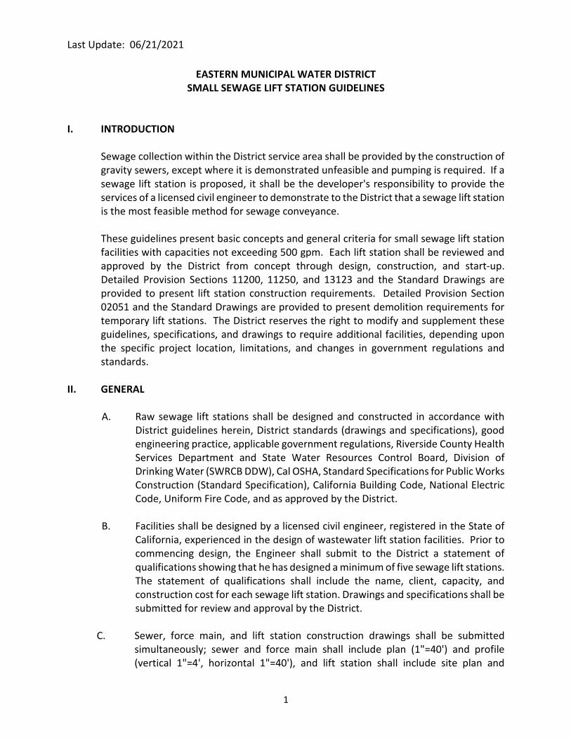
EASTERN MUNICIPAL WATER DISTRICT
SMALL SEWAGE LIFT STATION GUIDELINES
I. INTRODUCTION
Sewage collection within the District service area shall be provided by the construction of
gravity sewers, except where it is demonstrated unfeasible and pumping is required. If a
sewage lift station is proposed, it shall be the developer's responsibility to provide the
services of a licensed civil engineer to demonstrate to the District that a sewage lift station
is the most feasible method for sewage conveyance.
These guidelines present basic concepts and general criteria for small sewage lift station
facilities with capacities not exceeding 500 gpm. Each lift station shall be reviewed and
approved by the District from concept through design, construction, and start-up.
Detailed Provision Sections 11200, 11250, and 13123 and the Standard Drawings are
provided to present lift station construction requirements. Detailed Provision Section
02051 and the Standard Drawings are provided to present demolition requirements for
temporary lift stations. The District reserves the right to modify and supplement these
guidelines, specifications, and drawings to require additional facilities, depending upon
the specific project location, limitations, and changes in government regulations and
standards.
II. GENERAL
A. Raw sewage lift stations shall be designed and constructed in accordance with
District guidelines herein, District standards (drawings and specifications), good
engineering practice, applicable government regulations, Riverside County Health
Services Department and State Water Resources Control Board, Division of
Drinking Water (SWRCB DDW), Cal OSHA, Standard Specifications for Public Works
Construction (Standard Specification), California Building Code, National Electric
Code, Uniform Fire Code, and as approved by the District.
B. Facilities shall be designed by a licensed civil engineer, registered in the State of
California, experienced in the design of wastewater lift station facilities. Prior to
commencing design, the Engineer shall submit to the District a statement of
qualifications showing that he has designed a minimum of five sewage lift stations.
The statement of qualifications shall include the name, client, capacity, and
construction cost for each sewage lift station. Drawings and specifications shall be
submitted for review and approval by the District.
C. Sewer, force main, and lift station construction drawings shall be submitted
simultaneously; sewer and force main shall include plan (1"=40') and profile
(vertical 1"=4', horizontal 1"=40'), and lift station shall include site plan and

Last Update: 06/21/2021
2
standard drawings showing structural, mechanical, and electrical plans, sections,
and details with project specific requirements. Sewer and force main plans shall
be prepared in accordance with the District's "Guidelines for Sewer System Plans".
D. All costs of temporary facilities shall be borne by the developer.
E. Soils investigation shall be performed for the lift station site and related
interceptor sewer and force main.
F. A site-specific noise study shall be completed to ensure the outdoor emergency
standby generator's maximum noise level conforms to the city and/or county
noise ordinance at the property line. Noise study shall be submitted to the
District for review.
G. Upon approval and acceptance by the District, facilities shall be owned by the
District. Ownership shall include the lift station site and right-of-way for force
main and gravity sewers. Gravity sewers and force main shall be constructed on
District property, District right-of-way, or within public right-of-way whenever
possible. Easements for gravity sewers and force main will only be considered
under special conditions. All right-of-way and easement documents shall be
submitted and approved by District prior to approval of the construction drawings.
All right-of-way and easement documents shall be conveyed to the District and
recorded prior to acceptance of facilities.
H. Prior to completion of the facility and District acceptance, complete records shall
be furnished to the District including:
1. As-built record drawings.
2. Final approved shop drawings and submittals for all equipment and
materials.
3. As-built electrical and control diagrams.
4. Minimum three copies of Operation and Maintenance Manuals for all
equipment.
5. District staff training for station operation and equipment operation and
maintenance.
6. Right-of-way, grant deed, and easement records.
7. All construction and operating permits.

Last Update: 06/21/2021
3
III. PROCEDURES
A. Concept Meeting
1. Developer and developer's engineer shall have approved design conditions
before design and construction of a Temporary or Permanent Small
Sewage Lift Station. After the District has approved design conditions, the
Developer and Developer's engineer shall schedule and attend a concept
meeting with the District to review the requirements, guidelines, criteria,
right-of-way, and location of specific project facilities. District will provide
a list of approved materials.
2. Developer's engineer shall acquire and review these guidelines; Detailed
Provision Sections 11200, 11250 and 13123, and other Detailed Provision
Sections referenced in these guidelines; and the Standard Drawings.
B. Preliminary Design Documentation
Developer shall submit the following documentation to the District during the
preliminary design phase:
1. Complete calculations for sewage flows within the entire drainage area
tributary to the proposed lift station. See Section IV, Minimum
Requirements for details.
2. Preliminary Drawings (See Section IV Minimum Requirements)
a. Preliminary Site Layout include boundary limits, and existing and
proposed facilities within the surrounding area.
b. Preliminary drawings showing planned gravity collection system
within the lift station drainage area, including point(s) of
connection to existing or future gravity interceptor sewers, if any.
c. Preliminary drawings showing the proposed force main alignment
for the lift station including point of discharge.
3. Determination whether the proposed lift station will be temporary or
permanent.
4. Hydraulic Analysis, Pump Selection and Capacity (see Section IV Minimum
Requirements)

Last Update: 06/21/2021
4
a. Calculations establishing the required lift station capacity for initial
planned development and ultimate development.
b. Preliminary design calculations and information including required
capacity, hydraulic analyses, pump selections, and system curves,
and preliminary site layout. Sample design calculations are
included in Appendix A.
5. Flood Control Map
Flood control maps of proposed sewage lift station site. The sewage lift
station pad elevation shall be one foot higher than the 100-year flood
elevation.
6. Emergency Bypass Calculations
Developer's engineer shall submit calculations demonstrating that the
gravity sewer will not surcharge into the nearest sewer lateral while
bypassing the station from the onsite manhole.
C. 75% Submittal Design Phase
1. 75% Lift Station Construction Drawings
a. Submit 75% complete lift station construction drawings. Lift station
standard drawings shall include deltas revision symbols next to all
modifications to the lift station standard drawings.
b. Site plan shall be clearly legible. If site facilities, piping, and
electrical conduits cannot fit on one construction sheet legibly,
create two sheets. One sheet for above grade facilities and the
other sheet for below grade piping and electrical conduits.
c. Preliminary Site Plan shall show adjacent facilities i.e., street
grades, retention basins, proposed or existing pad elevations,
schools, etc.
d. Site Drainage shall flow away from wet well at a minimum fall of
0.5%.
e. Any modifications to the preliminary design documentation.
Last Update: 06/21/2021
5
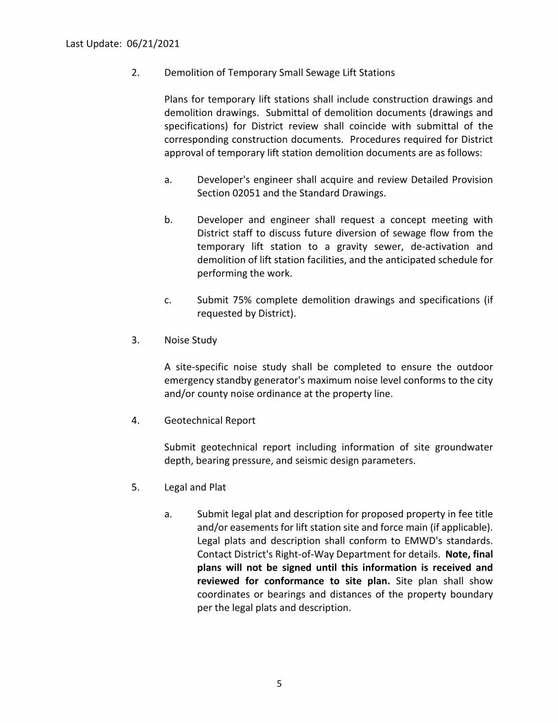
2. Demolition of Temporary Small Sewage Lift Stations
Plans for temporary lift stations shall include construction drawings and
demolition drawings. Submittal of demolition documents (drawings and
specifications) for District review shall coincide with submittal of the
corresponding construction documents. Procedures required for District
approval of temporary lift station demolition documents are as follows:
a. Developer's engineer shall acquire and review Detailed Provision
Section 02051 and the Standard Drawings.
b. Developer and engineer shall request a concept meeting with
District staff to discuss future diversion of sewage flow from the
temporary lift station to a gravity sewer, de-activation and
demolition of lift station facilities, and the anticipated schedule for
performing the work.
c. Submit 75% complete demolition drawings and specifications (if
requested by District).
3. Noise Study
A site-specific noise study shall be completed to ensure the outdoor
emergency standby generator's maximum noise level conforms to the city
and/or county noise ordinance at the property line.
4. Geotechnical Report
Submit geotechnical report including information of site groundwater
depth, bearing pressure, and seismic design parameters.
5. Legal and Plat
a. Submit legal plat and description for proposed property in fee title
and/or easements for lift station site and force main (if applicable).
Legal plats and description shall conform to EMWD's standards.
Contact District's Right-of-Way Department for details. Note, final
plans will not be signed until this information is received and
reviewed for conformance to site plan. Site plan shall show
coordinates or bearings and distances of the property boundary
per the legal plats and description.
Last Update: 06/21/2021
6
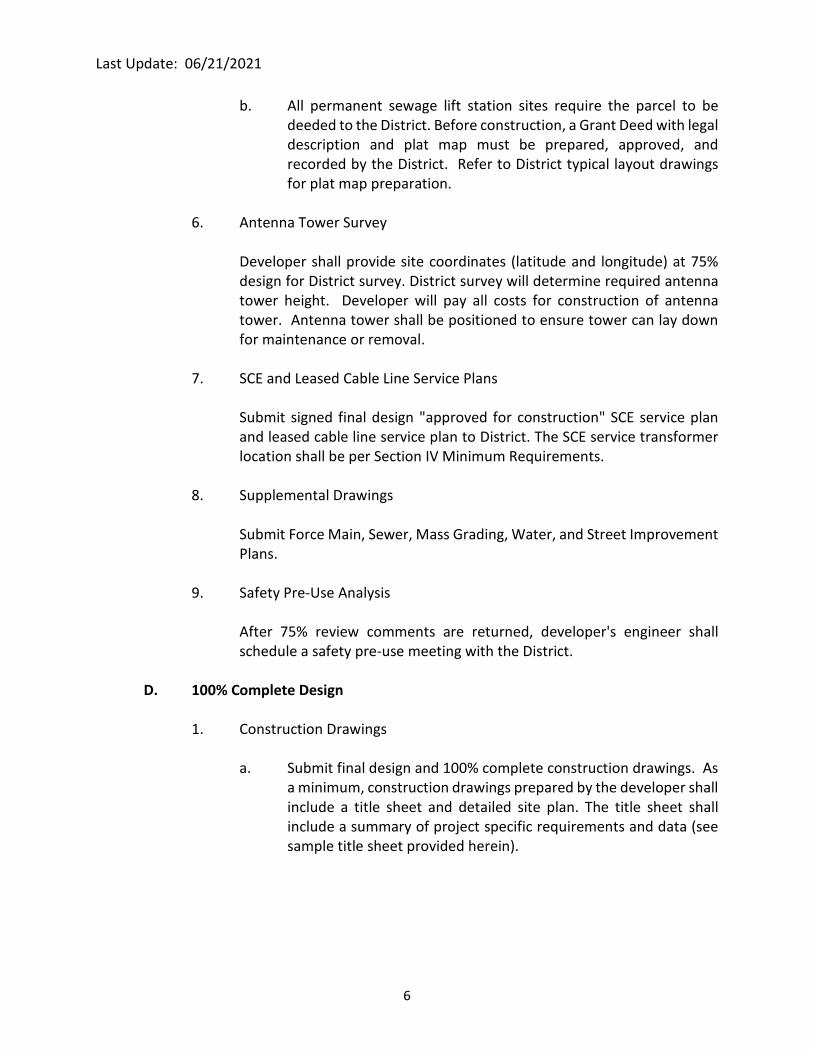
b. All permanent sewage lift station sites require the parcel to be
deeded to the District. Before construction, a Grant Deed with legal
description and plat map must be prepared, approved, and
recorded by the District. Refer to District typical layout drawings
for plat map preparation.
6. Antenna Tower Survey
Developer shall provide site coordinates (latitude and longitude) at 75%
design for District survey. District survey will determine required antenna
tower height. Developer will pay all costs for construction of antenna
tower. Antenna tower shall be positioned to ensure tower can lay down
for maintenance or removal.
7. SCE and Leased Cable Line Service Plans
Submit signed final design "approved for construction" SCE service plan
and leased cable line service plan to District. The SCE service transformer
location shall be per Section IV Minimum Requirements.
8. Supplemental Drawings
Submit Force Main, Sewer, Mass Grading, Water, and Street Improvement
Plans.
9. Safety Pre-Use Analysis
After 75% review comments are returned, developer's engineer shall
schedule a safety pre-use meeting with the District.
D. 100% Complete Design
1. Construction Drawings
a. Submit final design and 100% complete construction drawings. As
a minimum, construction drawings prepared by the developer shall
include a title sheet and detailed site plan. The title sheet shall
include a summary of project specific requirements and data (see
sample title sheet provided herein).

Last Update: 06/21/2021
7
2. Demolition of Temporary Small Sewage Lift Stations
a. Submit 100% complete demolition drawings. As a minimum,
demolition drawings prepared by the developer shall include a
detailed site plan. A sample demolition site plan is included herein
for reference. The demolition site plan shall show the removal of
all facilities not addressed by the Standard Drawings. As a
minimum, the site plan shall show demolition of site improvements
including fencing, walls, gates, paving, driveways, lighting,
electrical, and drainage facilities.
b. Submit a detailed cost estimate for performing the lift station
demolition work.
c. Demolition requirements shown on the Standard Drawings, and
contained in Detailed Provision Section 02051 represent minimum
District requirements. Depending upon the proposed re-use of the
temporary lift station site, developer may elect to require more
extensive demolition, including the complete removal of all below
grade facilities.
E. During Construction
1. Prior to construction (installation), shop drawing submittals for all
proposed equipment and materials shall be submitted to the District for
approval.
2. Construction of facilities shall be in accordance with approved
construction drawings and District specifications. District will provide
inspection of facilities, witness start-up, and provide final inspection of
facilities. District staff shall receive final operation and maintenance
manuals for all equipment a minimum of 10 working days prior to receiving
training for station operation and equipment operation. A factory trained
equipment manufacturer's representative shall provide the training.
F. Prior to Project Completion
Prior to completion of the facility and District acceptance, complete records shall
be furnished to the District including:
1. As-built record drawings.
2. Final approved shop drawings and submittals for all equipment and
materials.

Last Update: 06/21/2021
8
3. As-built electrical and control diagrams.
4. Minimum three copies of Operation and Maintenance Manuals for all
equipment.
5. District staff training for station operation and equipment operation and
maintenance.
6. Right-of-way, grant deed, and easement records.
IV. MINIMUM REQUIREMENTS
A. Capacity, Hydraulic Analysis, and Pump Selection
1. The theoretical calculated peak flow shall be based on the development to
be serviced with consideration of the entire drainage area and master
planned facilities. The design flow shall be determined by increasing the
theoretical calculated dry weather peak flow determined from entire
drainage area by 20% (i.e. peak flow x 1.20 = design flow). Pumping units
and wet well size shall be selected based on the design flow. Flows shall
be provided for initial and ultimate conditions. If necessary, lift stations
shall be located to maximize sewage collection for the entire drainage area
and shall conform to the District's Wastewater Master Plan. Lift station
pumping capacity may be dictated by minimum acceptable force main size
and velocity criteria herein.
2. Where Master Plan facilities have not been established, the developer
shall be responsible to prepare wastewater flow projections for the
drainage area.
3. Hydraulic calculations and system/pump curves for pump sizing and
required capacity shall be submitted for both initial and ultimate peak
flows. System curves shall be developed for friction coefficients of C=120
and C=140. System curves shall include minor friction losses (i.e. fittings
and valves in discharge piping at wet well and fittings in force main).
Pumps shall be selected based on friction coefficient of C=140.
Developer's engineer shall select a minimum of three District-approved
pump manufacturers and plot C=120 and C=140 system curves on each
pump curve.
4. Downstream sewers shall be evaluated to ensure adequate capacity is
available for receiving lift station sewage flow.

Last Update: 06/21/2021
9
5. Developer's engineer shall specify the pumping unit performance with a
design point, two operating conditions and a minimum shut off head.
B. Emergency Bypass Calculations
Developer's engineer shall submit calculations showing the gravity sewer soffit
elevation at the nearest sewer lateral and the onsite manhole invert elevation.
If the gravity sewer soffit elevation is more than 5' above the onsite manhole
invert elevation, the onsite manhole shall be used as a bypass manhole. If the
gravity sewer soffit elevation is less than 5' above the onsite manhole invert
elevation, the onsite manhole shall be used as a diversion manhole and a bypass
wet well shall also be provided (see Section IV, Part D).
C. Force Main Design Requirements
1. Force Main Diameter - Force main size (diameter) shall be based on the
following:
a. Lift station design flow rate (one pump operating) with minimum
velocity of 3 fps and maximum velocity of 6 fps.
b. Minimum size shall be 4-inch inside diameter. Where 4-inch mains
are required, two (2) parallel pipelines shall be constructed for
system reliability. Each force main shall be provided with the
necessary valves and fittings to allow operation of either force main
or both force mains.
c. Where a single 4-inch force main is inadequate to convey the peak
flow rate (i.e. force main velocity exceeds maximum allowable
velocity), the next larger size pipe diameter shall be used.
d. Where force main length exceeds 6,000 L.F., two (2) parallel
pipelines shall be constructed for system reliability. Each force
main shall be provided with the necessary valves and fittings to
allow for operation of either force main or both force mains.
2. Force Main Material - Material shall be PVC per ANSI/AWWA C900
(minimum DR-18). Pipeline shall be constructed using restrained joints per
District Standard Drawing B-663.

Last Update: 06/21/2021
10
3. Force Main Profile - Force main profile shall avoid intermediate high points
if feasible. All high points shall be provided with combination sewage air
and vacuum valve installation and special corrosive resistant pipeline
materials.
4. Force Main Minimum Cover - Onsite pipe cover shall be minimum
48-inches.
5. Force Main Connection Manhole - Where force main connects to an
existing discharge manhole, the discharge manhole shall be lined per
Standard Detailed Provision Section 09811 at developer's expense. The
District may require multiple manholes be lined at developer's expense.
Where force main connects to a new discharge manhole, the discharge
manhole shall be polymer concrete manufactured by Armorock or equal
at the developer's expense.
D. Site Layout of Proposed Facilities
Location of all proposed facilities shall be in reference to site property lines or
easement boundary. As a minimum, the lift station site plan shall show the
following:
1. Site Fence or Block Wall
Location of all site improvements, including site fencing or masonry block
walls and access gate(s) shall be shown on the drawings. Fence or block
wall shall be provided with coordinates or bearing and distances on the
site layout. Provide construction details for site fencing, access gate(s) or
block wall if District standard fencing and gate(s) are not specified.
All lift stations shall have a street address sign affixed to the fence or access
gate at the front of the station.
a. Fence
As a minimum, site shall be secured by commercial grade 8-foot
high chainlink fence with 3-strand barbed wire or an 8-foot high
masonry block wall. Access gate(s) shall include minimum 20-foot
wide double gate for vehicles. 8-foot rail chainlink fencing and
gates shall be provided in accordance with District Standard
Drawing D-672.

Last Update: 06/21/2021
11
b. Block Wall
1. Where masonry block walls are selected for site security,
label top of wall and top of footing for each wall segment.
Walls and wall footings shall be constructed level.
2. Walls shall step as required to provide a minimum of 8'-0"
height from outside finished grade. Provide a construction
detail for masonry block wall and concrete footing showing
all dimensions, reinforcing steel, block type, construction
joints, and grouting requirements.
3. Construction joints shall be placed every 30 feet.
4. Footing shall be "T" or "L" type. Edge of footing shall be
placed on the edge of the property line.
5. The block type shall be precision faced. If the developer
prefers a different block type (split face, slump, etc.), the
developer shall submit the proposed block type to the
District's maintenance department for approval.
6. Provide cap on top of the block wall.
7. Block wall shall be coated with an anti-graffiti coating.
8. Block wall shall be fully grouted.
9. Submit Structural Design Calculations in accordance with
the seismic design requirements on Construction Drawing
G-1 and Detailed Provisions, Section 04220, Concrete
Masonry Units.
2. Site Grading
Finished grades for all proposed facilities and site improvements. As a
minimum, grades (elevations) shall be provided for all concrete slabs and
roofs, asphalt concrete paving (along pavement edges and flow lines,
adjacent to concrete slabs and roofs, etc.), masonry block walls and
footings, and finish grading adjacent to site improvements.
Entire site shall be provided with asphalt concrete pavement or concrete
pavement, and adequate drainage facilities (minimum fall of 0.5%). Access
driveway(s) to the site shall be 20-foot wide (minimum) and constructed
Last Update: 06/21/2021
12
of asphalt concrete pavement or reinforced concrete pavement. Asphalt
concrete pavement or reinforced concrete pavement shall be designed to
accommodate AASHTO H20-44 vehicle loading.
If required by the District, based on proximity of the facility to other public
facilities, residences, or buildings, hardscape shall be provided in
accordance with the surrounding area. Landscaping shall be avoided.
3. Design Vehicle
Site shall be of adequate size to operate, maintain, and repair the lift
station facilities incorporating access for truck cranes and sewer cleaning
trucks (Vactor trucks). Design AASHTO-2018 SU-40.
4. Potable Water
Potable water shall be provided to the site by hose bibs with antisiphon
devices, water meter per Standard Drawing B-342 and a backflow
prevention device per Standard Drawing No. B-597A as approved by the
District and SWRCB DDW. Potable water service shall be hot tapped or
provided with a tapping sleeve in accordance with the District's Standard
Drawings. See typical site plan for more information.
Separation from water lines shall be in accordance with SWRCB DDW.
Additionally, a minimum 10-foot horizontal clearance shall be provided
from site walls, site fencing, electrical facilities, storm drain facilities, and
gravity sewer.
5. Sewer Facilities
a. Gravity Sewer and Manholes - Location of gravity sewer and
manholes. Provide bearings and distances along each gravity
sewer segment shown on the Site Plan. Provide invert elevations
(inlet and outlet) at each manhole. Gravity sewers shall be labeled
with pipe size and material. Gravity sewer pipe material shall be
the same as the gravity sewer pipe material from the first offsite
manhole to the lift station manhole. Manholes shall be labeled
with size and Standard Drawing reference.
b. Force Main and Emergency Bypass Connection - Location of force
main and emergency bypass connection. Provide bearings and
distances along each force main segment shown on the Site Plan.
Provide center grade elevations at each horizontal and vertical
point of inflection (HPI and VPI). Force main shall be labeled with

Last Update: 06/21/2021
13
pipe size, material, and class. If the force main crosses a significant
number of utilities, the District may request for a pipe profile
demonstrating adequate clearances between utilities.
c. Emergency Bypass System
Based on the results of the emergency bypass calculations, the lift
station shall be provided with one of the following:
i. Gravity sewer soffit elevation at nearest sewer lateral
greater than 5' above onsite manhole invert elevation.
5' ID Bypass Manhole per Lift Station Standard
Drawing C-1.
ii. Gravity sewer soffit elevation at nearest sewer lateral less
than 5' above onsite manhole invert elevation.
5' ID Diversion Manhole per Lift Station Standard
Drawing C-1 with stop logs.
Bypass Wet Well per Lift Station Standard Drawing S-3
(diameter of Bypass Wet Well shall match diameter of
Wet Well).
6. Electrical Facilities and Appurtenances
a. Motor Control Center- The motor control center (MCC) Panel shall
be oriented north or east to avoid excessive sun exposure.
b. Radio Antenna Tower- A radio antenna tower shall be provided for
District SCADA and network communications at developer's
expense.
c. Site Lighting - Site shall be provided with a lighting system designed
to minimize off site impacts while maintaining functionality for
maintenance personnel working on lift station components. As a
minimum, each site shall be provided with two (2) pole mounted
site fixtures. Each pole mounted light fixture shall have two lights
an area light and a work light. The "area light" shall be LED (light
emitting diode) type activated by a photocell and the "work light"
shall be an LED type activated by a manual switch located in the
Main Control Panel. "Area lights" shall comply with County of
Riverside Ordinance Number 655 - Regulating Light Pollution.
Last Update: 06/21/2021
14
d. SCE Service Transformer- Utility transformer and metering section
shall be located in a separate fenced-in area (see Typical Site Plans).
e. Electrical Conduit, Pull Boxes, Junction Boxes- Location of each
electrical conduit, pull box, junction box, and SCE service and
transformer. Refer to Conduit Schedule on Electrical Drawings for
conduit destinations. Label all conduits shown in the Conduit
Schedule.
7. Odor Control Components
Odor control components shall include: concrete slab for emergency
shower and eyewash station, concrete pad for District furnished chemical
storage tank, 120v receptacle for District furnished chemical feed pump,
and conduit sleeve from receptacle stanchion to wet well. Emergency
shower and eyewash station slab shall be located on the side of the
chemical tank pad where the chemical delivery truck will be logically
positioned.
8. Site Security System
If required by District, a site security system (cameras, intrusion switches,
etc.) shall be provided. The site security system may require connection
to a leased cable line in lieu of a microwave system in order to transmit
security data to the District. Developer shall coordinate and obtain leased
cable line service to the lift station site, if required by District.
E. Lift Station Components
1. Raw sewage lift station shall be the submersible type with 100%
redundancy, electrical service, switchgear, emergency power, and
appurtenances. Standard Drawings M-1A, M-1B, M-2, ME-1, and ME-2 are
provided to present equipment and piping plans, sections, and details for
the lift station.
2. Raw Sewage Pump Requirements
a. Number of pumps furnished shall provide complete redundancy.
Minimum of two identical pumps each sized for 100% station
capacity shall be installed. Typically, constant speed pumps will be
provided; however, discharge to the downstream system may
require use of variable speed drives.

Last Update: 06/21/2021
15
b. Raw sewage non-clog submersible pumps. Pump impellers shall be
enclosed single port, recessed vortex, or grinder type. The specific
pump impeller type to be used for the project will be determined
by the District based on application and availability.
c. Minimum 4-inch discharge.
d. Ability to pass minimum 3-inch diameter sphere.
e. Maximum 1800 rpm explosion-proof submersible motor with
moisture and temperature sensors.
f. Motor and cooling rating suitable to run dry for 15 minutes without
damage to the pump.
g. UL or Factory Mutual explosion-proof rating without being
submerged.
h. Constructed of corrosion resistant materials and provided with
corrosion resistant factory coating.
i. Acceptable manufacturers are Essco, Wilo-EMU, Fairbanks--
Nijhuis, Wemco Flowserve, Xylem-Flygt, and ABS.
3. Wet Well Requirements
a. Wet Well Material - Class IV reinforced concrete pipe (RCP) per
ASTM C76 with two circular reinforcement cages (quadrant or
elliptical cages will not be allowed) and flush bell and spigot joints.
Bell and spigot joints shall be provided with rubber gaskets and
shall be suitable for a hydrostatic head of 50 feet per ASTM C361.
Wet well shall also include reinforced concrete base and cover.
Wet well reinforced concrete base shall be placed on a 12-inch
thick mat of crushed miscellaneous base per SSPWC Section 200-
2.4, Fine Gradation. Interior concrete surfaces (including wall and
roof) shall be coated. Wet well bottom shall be provided with
concrete fillets sloping towards the pumps.
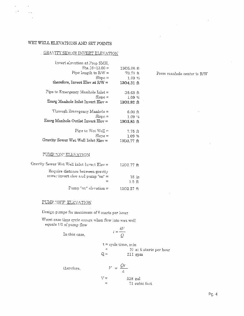
b. Wet Well Sizing - Wet well shall be sized based on maximum pump
motor cycling time of six starts per hour at 1/2 design capacity and
to provide adequate spacing for installation of two pumping units
(see Table on Standard Drawing G-1 for wet well size versus flow
capacity).

Last Update: 06/21/2021
16
c. Wet Well Roof - Concrete roof shall have a hatch opening (one
hatch for both pumps) for pump removal/installation. Equipment
access hatches shall be constructed of Type 316 stainless steel as
manufactured by U.S.F. Fabrication, Flygt, Bilco, or equal, with
lockable diamond plate covers, safety chain, spring assisted hinges,
and swing-out interior safety grating. A removable handrail system
shall be provided around hatch opening (Railguard 200 by Garlock
Safety Systems, or equal).
d. Wet Well Discharge Piping - Discharge piping inside the wet well
shall be flanged, Schedule 40 316 stainless steel. All stainless steel
piping, fittings, and flanges shall be shop welded (field welding not
permitted except where noted on District Standard Drawings). All
welds shall be pickled and passivated in the shop (pickling paste
shall be applied to District approved field welds). Discharge piping
shall be designed for a maximum velocity of 6 to 8 feet per second.
Discharge piping shall be properly supported with pipe supports.
Pipe supports, brackets, and all other equipment and fasteners
within the wet well shall be 316 stainless steel.
e. Onsite Manhole - All collection sewers shall join and enter a single
manhole just prior to entering the wet well. Only one sewer shall
enter the wet well to allow the District to plug influent sewer and
bypass around wet well for maintenance and repairs.
f. Bypass Wet Well - The bypass wet well shall be provided with a
single inlet for bypass events.
4. Pump Discharge Piping Out of Wet Well
a. Discharge Piping Location - Discharge from each pump shall exit
the wet well below grade, then rise above grade for location of
check valves and isolation plug valves.
b. Valves - Each pump shall be provided with 150 lb swing check valve
(AWWA C508 with bronze trim) and shut-off valves (eccentric
non-lubricated plug valve). Sewage combination air and vacuum
valves shall be provided at high points.
c. Bypass Connection - A bypass connection to the force main shall
be provided for station bypass with portable pumps.
d. Piping Alignment - Whenever possible, influent and effluent piping
shall be perpendicular or parallel.

Last Update: 06/21/2021
17
e. Gooseneck - For lift stations with force main discharge elevation
lower than the lift station elevation (downhill force mains), the
abovegrade discharge piping shall include a gooseneck to keep the
flow meter full.
5. Laser Level System
A laser level system shall be provided to control the operation of the
pumps.
6. Davit Crane
A permanent davit crane shall be provided.
F. Electrical Components
1. Code Requirements - All electrical equipment shall be in accordance with
the NEC and, where applicable, meet all requirements for hazardous
locations. Developer shall coordinate with the electrical utility providing
electrical service. Station shall be provided with a separate utility
transformer and metering section with main circuit breaker. Primary
power to the station shall be 480 volt, 60 Hz, 3-phase service per utility
providers' standards. Single-phase 120-volt power shall be provided for
lights, controls, convenience receptacles, and miscellaneous equipment.
Provide a minimum of four spare 20A, 120-volt circuit breakers. All conduit
shall be run concealed below grade or in concrete slabs, and shall not
impose tripping or maintenance hazards. All exposed conduit shall be pvc-
coated rigid steel pipe.
2. Electric Switchgear - Electric switchgear shall be mounted in a NEMA 1
gasketed enclosure (with NEMA 3R wrapper) Motor Control Center with
removable buckets, and shall include, as a minimum, main circuit breaker,
motor starters with thermal overload protection, selector switch (hand-
off-auto), run and fail lights, and elapsed time meter. Switchgear shall be
General Electric, Eaton/Cutler Hammer, Allen-Bradley, or Schneider
Electric/Square D (no substitutes). The MCC doors shall face north or east.
3. Pump Controls - Complete controls for automatic pump operation shall be
provided per Standard Drawing E-4.
4. Sunshade Structure - An electrical panel sunshade structure shall be
provided.

Last Update: 06/21/2021
18
5. An electrical short circuit/coordination study, arc flash hazard study, and
field testing of the electrical system shall be performed.
G. Emergency Power
1. Lift station facilities shall include permanent emergency power generation
facilities.
2. Generator set shall be "pre-certified"/"pre-approved" by South Coast Air
Quality Management District (SCAQMD) for emergency standby power
service, and shall meet all current SCAQMD air emission regulations. The
Standby Generator Set shall meet the applicable tier standards required by
SCAQMD Best Available Control Technology (BACT) requirements and
SCAQMD Rule 1470.
A Level 3 diesel particulate filter (DPF) system verified by California Air
Resources Board shall be provided at the developer's expense if required
to meet the emission requirements of SCAQMD Rule 1470. A load bank
system shall be supplied with all generator sets. Load bank system shall
include an automatic load controller capable of auto-loading at multiple
load steps and dropping the generator load. Developer's engineer shall
determine whether a passive DPF system is required.
All SCAQMD permits, including payment of fees for the first year of
operation shall be furnished by developer. Permits shall have no less than
a 200-hour annual operating limit with no less than 50 hours for
maintenance and testing. The SCAQMD permit to construct shall be
transferred into a permit to operate prior to acceptance by the District.
3. The emergency standby generator shall be supplied by Caterpillar,
Cummins, or Generac.
4. If the District requires the developer to provide a standby generator that
is larger than what is necessary to support the proposed lift station
equipment (based on future development flows to the lift station), then
the developer shall provide a load bank sized to provide the difference
between the proposed equipment load and the future equipment load.
5. Automatic transfer switch (ATS) shall be provided to switch from normal
utility power to standby emergency power upon normal power fail, and
switch back to normal power when restored. ATS shall have indicating
lights for normal power, emergency power, and a digital panel indicating
volts and amps. Acceptable manufacturers are Olympian, ASCO, or
Russelectric.

Last Update: 06/21/2021
19
H. Telemetry Equipment
District will furnish, install, and program telemetry equipment system, including remote
telemetry unit (RTU) to transmit alarm conditions to existing SCADA system. Contractor
shall terminate all alarm signals on terminal blocks in the Main Control Panel (MCP).
Contractor shall connect from MCP terminal blocks to District furnished RTU terminal
block.

Last Update: 06/21/2021
20
[Page Left Intentionally Blank]

APPENDIX A
SAMPLE DESIGN CALCULATIONS

[PAGE LEFT INTENTIONALLY BLANK]

[PAGE LEFT INTENTIONALLY BLANK]


[PAGE LEFT INTENTIONALLY BLANK]


TABLES

[PAGE LEFT INTENTIONALLY BLANK]

Last Update: 06/21/2021
TABLE 1
RELATED DISTRICT STANDARD DRAWINGS
Refer to the latest Standard Drawings located at the following web site (https://www.emwd.org/water-standard-drawings)
(https://www.emwd.org/sewer-standard-drawings)
Standard
Dwg. No.
Description
B-286B
Trench Backfill (for PVC forcemain)
B-342 1.5" Meter Installation
B-344A 2" Copper Service Connection
B-590 5/8" Meter Service Connection, 1" Copper Tubing
B-590A 5/8" Service Connection, 1" Copper Tubing
B-591 1" Meter Service Connection, 1" Copper Tubing
B-591A 1" Service connection, 1" Copper Tubing
B-597 Backflow Prevention Assembly Installation Diagram
B-597A Reduced Pressure Backflow Preventer Assembly for sizes 3/4" through 2'
B-656 Location Wire Installation
B-658 Service Connection 1" through 4" on Water Appurtenance Lateral or
Watermain 16" or Larger
B-663 Standard Restraint (Tee, Dead End, Bend)
B-665 Guard & Marker Posts
D-672 Chain Link Fence Details
SB-08 Locking Type Manhole Cover & Frame
SB-30 Reinforced Precast Shallow Manhole
SB-53 Precast Reinforced Concrete 60" & 72" ID Flat Top Manhole
SB-61 Manhole Cover & Frame
SB-157 Pipe Zone Bedding for Sewer Pipe
SB-158 Trench Backfill for Sewer Pipe
SB-159 Classification of Pipe Zone Bedding for Sewer Pipe

[PAGE LEFT INTENTIONALLY BLANK]


