East Pier - Building 7, 50 Lewis Street, East Boston, MA ... (VOCs), Semi-Volatile Organic Carbons...
35
-
Upload
duongkhanh -
Category
Documents
-
view
220 -
download
1
Transcript of East Pier - Building 7, 50 Lewis Street, East Boston, MA ... (VOCs), Semi-Volatile Organic Carbons...


127 Hartwell Street, Suite 3 West Boylston, Massachusetts 01583 Tel: 774.450.7177 Fax: 888.835.0617 www.lrt-llc.net
February 28, 2013 U.S. Environmental Protection Agency-Region 1 5 Post Office Square, Suite 100 Mail Code OEP06-4 Boston, Massachusetts 02109-3912 Attn.: Remediation General Permit NOI Processing Reference: Notice of Intent NPDES Remediation General Permit East Pier – Building 7 Boston, Massachusetts LRT Reference #2-1074 To whom it may concern:
On behalf of W.L. French Excavation Corporation (French), Lockwood Remediation Technologies, LLC (LRT) has prepared this Notice of Intent (NOI) for coverage under the National Pollutant Discharge Elimination System (NPDES) Remediation General Permit (RGP), Massachusetts General Permit (MAG910000). This NOI was prepared in accordance with the general requirements of the NPDES and related guidance documentation provided by the US Environmental Protection Agency (EPA). The completed NOI form is provided in Appendix A. Site Information This NOI has been prepared for the management of water generated from an excavation during the building construction at East Pier – Building 7 in East Boston, Massachusetts (the Site); please refer to Figure 1 for a locus map and an overview of the immediate area surrounding the Site. The work area, located along the former Pier One site on Marginal Street, is depicted in Figure 2 along with the proposed treated water discharge location. Work Summary Previous construction efforts in 2007 and 2008 completed the installation of steel sheeting piles at the Site. The new work scope at the site includes the installation of approximately 60 additional piles, foundation systems, building construction and roadway and sidewalk improvements. In order to complete portions of this work, dewatering is required. Water generated from the excavation will be handled in accordance with a Best Management Practices Plan included in Appendix B. To characterize water from the excavation, LRT collected a representative groundwater sample on February 21, 2013. This sample was analyzed for the parameters in accordance with the NPDES RGP Appendix III, Category 3B known contaminated sites dewatering. Laboratory data reports for this sample are provided in Appendix C.

Notice of Intent – Remediation General Permit Page 2 East Pier – Building 7, East Boston, MA February 28, 2013
Discharge and Receiving Surface Water Information A groundwater sample collected by LRT was submitted for the following analyses; Total Suspended Solids (TSS), Total Residual Chlorine (TRC), Total Petroleum Hydrocarbons (TPH), Volatile Organic Carbons (VOCs), Semi-Volatile Organic Carbons (SVOCs) including Polycyclic Aromatic Hydrocarbons (PAH), Total Polychlorinated Biphenyls (PCBs), Chloride, and Metals including: Antimony, Arsenic, Cadmium, Chromium III (trivalent), Chromium VI (hexavalent), Copper, Lead, Mercury, Nickel, Selenium, Silver, Zinc and Iron. Groundwater at the site was based on analytical results of samples collected by LRT, there were detectable concentrations of TSS, SVOCs, cyanide and metals. SVOCs will be reduced via granular activated carbon (GAC). Cyanide will be reduced with an ion exchange media. Several metals currently exceed the proposed discharge criteria. These elevated concentrations detected in the water characterization however are assumed to be associated with the TSS. The TSS is expected to be significantly reduced via settling occurring in influent equalization tank and also by the filtration that occurs as part of the wastewater treatment plant provided. Refer to Figure 3 for a proposed water treatment system layout. Calculation of Dilution Criteria For applications in Massachusetts, the following formula is used to calculate site specific dilution criteria: DF = (Qd + Qs)/Qd DF = Dilution Factor Qd = Maximum flow rate of the discharge in cubic feet per second (cfs) Qs = Receiving water 7Q10 flow (cfs) where 7Q10 is the minimum flow for seven consecutive days with a reoccurrence interval of 10 years The receiving water for the dewatering discharge for the site is the Inner Boston Harbor. Since the receiving body is salt water, dilution calculations are not applicable. The applicable discharge standards for the site will be defined as saltwater standards in accordance with Appendix III of the NPDES RGP. Consultation with Federal Services LRT reviewed online electronic data viewers and databases from the Massachusetts Geographical Information System (MassGIS) and the Massachusetts Division of Fisheries and Wildlife (MassWildlife; Natural Heritage and Endangered Species Program), and the U.S. National Parks Service Natural Historic Places (NPS). Based on this review, neither the Site nor the point where the proposed discharge reaches the receiving surface water body are Areas of Critical Environmental Concern (ACEC), Habitats of Rare Wetland Wildlife, Habitats of Rare Species or Estimated Habitats of Rare Wildlife or listed as a National Historic Place.

Notice of Intent – Remediation General Permit Page 3 East Pier – Building 7, East Boston, MA February 28, 2013
Coverage under NPDES RGP It is our opinion that the proposed discharge is eligible for coverage under the NPDES RGP. On behalf of French, we are requesting coverage under the NPDES RGP for the discharge of wastewater during construction activities to the Inner Boston Harbor. The enclosed NOI form provides required information on the general site conditions, discharge, treatment system, receiving water, and consultation with federal services. For this project, French is the operator that has operational control over the construction plans and specifications, including the ability to make modifications to those plans and specifications. Please feel free to contact us at 774-450-7177 or at [email protected] if you have any questions or if you require additional information. Sincerely, Lockwood Remediation Technologies, LLC
Paul Lockwood Paul Lockwood President Attachments: Figure 1 Locus Plan Figure 2 Site Plan Figure 3 Proposed Water Treatment System Schematic
Appendix A – NOI Form Appendix B – Best Management Practices Plan Appendix C – Laboratory Data

Figures

Source: USGS Topographic Map 1987, US Department of the Interior Site Location: Latitude: 42.367335 Longitude: -71.040671
Figure 1 – Locus Plan W.L. French Excavation Corporation East Pier – Building 7 Boston, MA
127 Hartwell Street, Suite 3 West Boylston, Massachusetts 01583 Tel: 774.450.7177 Fax: 888.835.0617 www.lrt-llc.net
SITE

Source: Google Maps Approximate Site Boundary Discharge Location
Figure 2 – Site Plan W.L. French Excavating Corporation East Pier – Building 7 Boston, Massachusetts
127 Hartwell Street, Suite 3 West Boylston, Massachusetts 01583 Tel: 774.450.7177 Fax: 888.835.0617 www.lrt-llc.net

Notes 1. Generic layout only. 2. Figure not to scale. 3. System rated for 500 GPM 4. Carbon Vessels and pH Adjustment System are outlined as optional
Figure 3 - Proposed Water Treatment System Schematic W.L. French Excavation Corporation East Pier – Building 7 Boston, Massachusetts
127 Hartwell Street, Suite 3 West Boylston, Massachusetts 01583 Tel: 774.450.7177 Fax: 888.835.0617 www.lrt-llc.net
4” Flow Meter Discharge
21,000-gallon Frac Tank
Centrifugal Pump Skid
Multi-Bag Filter Skid
Carbon Vessels
pH Adjustment System
Influent Optional
Optional
Resin Vessel

Appendix A – NOI Form

B. Suggested Form for Notice of Intent (NOI) for the Remediation General Permit
1. General site information. Please provide the following information about the site:
a) Name of facility/site: Facility/site address:
Location of facility/site:
longitude:__________ latitude:__________
Facility SIC code(s): Street:
b) Name of facility/site owner: Town:
Email address of owner: State: Zip: County:
Telephone no.of facility/site owner :
Fax no. of facility/site owner : Ow ner is (check one): 1. Federal____ 2. State/Tribal_____
3. Private______ 4. other, if so, describe: Address of owner (if different from site):
Street:
Town: State: Zip: County:
c) Legal name of operator: Operator telephone no:
Operator fax no.: Operator email:
Operator contact name and title:
Address of operator (if different from owner): Street:
Town: State: Zip: County:
d) Check “yes” or “no” for the following:
1. Has a prior NPDES permit exclusion been granted for the discharge? Yes___ No___, if “yes,” number:
2. Has a prior NPDES application (Form 1 & 2C) ever been filed for the discharge? Yes___ No___, if “yes,” date and tracking #:
3. Is the discharge a “new discharge”as defined by 40 CFR 122.2? Yes___ No___
4. For sites in Massachusetts, is the discharge covered under the MA Contingency Plan (MCP) and exempt from state permitting? Yes__ No__
Remediation General Permit - Notice of Intent 10

e) Is site/facility subject to any State permitting or other action which is causing the f) Is the site/facility covered by any other EP A permit, includ ing:
generation of discharge? Yes___ No___ 1. multi-sector storm water general permit? Y___ N___, if Y, number:
If “yes,” please list: 2. phase I or II construction storm water general permit? Y___ N___,
1. site identification # assigned by the state of NH or MA: if Y, number:
2. permit or license # assigned: 3. individual NPDES permit? Y___ N___, if Y, number:
3. state agency contact information: name, location, and telephone number: 4. any o ther water quality related permit? Y___ N___, if Y, number:
2. Discharge information. Please provide information about the discharge, (attaching additional sheets as needed) including:
a) Describe the discharge activities for which the owner/applicant is seeking coverage:
b) Provide the
following
information
about each
discharge:
1) Number of
discharge
points:
2) What is the maximum and average flow rate of discharge (in cubic feet per second, ft3/s)? Max. flow____________
Average flow__________ Is maximum flow a design value? Y___ N____
For average flow, include the units and appropriate notation if this value is a design value or estimate if not available.
3) Latitude and longitude of each discharge within 100 feet: pt.1:long.______ lat.______; pt.2: long.______ lat.______; pt.3: long.______ lat.______;
pt.4:long.______ lat.______; pt.5: long.______ lat.______; pt.6:long.______ lat.______; pt.7: long.______ lat.______; pt.8:long.______ lat.______; etc.
4) If hydrostatic testing, total volume of the discharge (gals): 5) Is the discharge intermittent______or seasonal______?
Is discharge ongoing Yes ____ No______?
c) Expected dates of discharge (mm/dd/yy): start_____________ end_________________
d) Please attach a line drawing or flow schematic showing water flow through the facility including:
1. sources of intake water, 2. contributing flow from the operation, 3. treatment units, and 4. discharge points and receiving waters(s).
Remediation General Permit - Notice of Intent 11

3. Contaminant information. In order to complete this section, the applicant will need to take a minimum of one sample of the untreated water and have it analyzed for all
of the parameters listed in Appendix III. Historical data, (i.e., data taken no more than 2 years prior to the effective date of the permit) may be used if obtained pursuant to:
i. Massachusetts’ regulations 310 CMR 40.0000, the Massachusetts Contingency Plan (“Chapter 21E”); ii. New Hampshire’s Title 50 RSA 485-A: Water Pollution and
Waste Disposal or Title 50 RSA 485-C: Groundwater Protection Act; or iii. an EPA permit exclusion letter issued pursuant to 40 CFR 122 .3, provided the data was
analyzed with test methods that meet the requirements of this permit. Otherwise, a new sample shall be taken and analyzed.
a) Based on the analysis of the sample(s) of the untreated influent, the applicant must check the box of the sub-categories that the potential discharge falls within.
Gasoline O nly VOC Only Primarily Metals Urban Fill Sites Contaminated Sumps Mixed Contaminants Aquifer Testing
Fuel Oils (and VOC with Other Petroleum with Other Listed Contaminated Contaminated Hydrostatic Testing of Well Development
Other Oils) only Contaminants Contaminants Sites Dredge Condensates Pipelines/Tanks or Rehabilitation
b) Based on the analysis of the untreated influent, the applicant must indicate whether each listed chemical is believed present or believed absent in the potential
discharge. Attach additional sheets as needed.
PARAMETER Believe Absent
Believe Present
# of Samples
Type of Sample
Analytical Method
Minimum Level (ML) of
Maximum daily value Avg. daily value
(1 minimum)
(e.g., grab) Used (method #)
Test Method concentration (ug/l)
mass (kg) concentration (ug/l)
mass (kg)
1. Total Suspended Solids
2. Total Residual Chlorine
3. Total Petroleum Hydrocarbons
4. Cyanide
5. Benzene
6. Toluene
7. Ethylbenzene
8. (m,p,o) Xylenes
9. Total BTEX4
4BTEX = Sum of Benzene, Toluene, Ethylbenzene, total Xylenes.
Remediation General Permit - Notice of Intent 12

PARAMETER Believe Absent
Believe Present
# of Samples
Type of Sample (e.g.,
Analytical Method
Minimum Level (ML) of
Maximum daily value Avg. daily value
(1 minimum)
grab) Used (method #)
Test Method concentration (ug/l)
mass (kg) concentration (ug/l)
mass (kg)
10. Ethylene Dibromide 5
(1,2- Dibromo-methane)
11. Methyl-tert-Butyl Ether (MtBE)
12. tert-Butyl Alcohol (TBA)
13. tert-Amyl Methyl Ether (TAME)
14. Naphthalene
15. Carbon Tetrachloride
16. 1,4 Dichlorobenzene
17. 1,2 Dichlorobenzene
18. 1,3 Dichlorobenzene
19. 1,1 Dichloroethane
20. 1,2 Dichloroethane
21. 1,1 Dichloroethylene
22. cis-1,2 Dichloroethylene
23. Dichloromethane (Methylene Chloride)
24. Tetrachloroethylene
5EDB is a groundwater contaminant at fuel spill and pesticide application sites in New England.
Remediation General Permit - Notice of Intent 13

PARAMETER Believe Absent
Believe Present
# of Samples
Type of Sample (e.g.,
Analytical Method Used
Minimum Level (ML) of Test
Maximum daily value Avg. daily Value
(1 minimum)
grab) (method #) Method concentration (ug/l)
mass (kg) concentration (ug/l)
mass (kg)
25. 1,1,1 Trichloroethane
26. 1,1,2 Trichloroethane
27. Trichloroethylene
28. Vinyl Chloride
29. Acetone
30. 1,4 Dioxane
31. Total Phenols
32. Pentachlorophenol
33. Total Phthalates 6
(Phthalate esthers)
34. Bis (2-Ethylhexyl) Phthalate [Di(ethylhexyl) Phthalate]
35. Total Group I Polycyclic Aromatic Hydrocarbons (PAH)
a. Benzo(a) Anthracene
b. Benzo(a) Pyrene
c. Benzo(b)Fluoranthene
d. Benzo(k) Fluoranthene
e. Chrysene
6The sum of individual phthalate compounds.
Remediation General Permit - Notice of Intent 14

PARAMETER Believe Absent
Believe Present
# of Samples
Type of Sample (e.g.,
Analytical Method Used
Minimum Level (ML) of
Maximum daily value Average daily value
(1 minimum)
grab) (method #) Test Method concentration (ug/l)
mass (kg) concentration (ug/l)
mass (kg)
f. Dibenzo(a,h) anthracene
g. Indeno(1,2,3-cd) Pyrene
36. Total Group II Polycyclic Aromatic Hydrocarbons (PAH)
h. Acenaphthene
i. Acenaphthylene
j. Anthracene
k. Benzo(ghi) Perylene
l. Fluoranthene
m. Fluorene
n. Naphthalene-
o. Phenanthrene
p. Pyrene
37. Total Polychlorinated Biphenyls (PCBs)
38. Antimony
39. Arsenic
40. Cadmium
41. Chromium III
42. Chromium VI
Remediation General Permit - Notice of Intent 15
PARAMETER Believe Absent
Believe Present
# of Samples
Type of Sample (e.g.,
Analytical Method
Minimum Level (ML) of
Maximum daily value Avg. daily value
(1 minimum)
grab) Used (method #)
Test Method concentration (ug/l)
mass (kg) concentration (ug/l)
mass (kg)
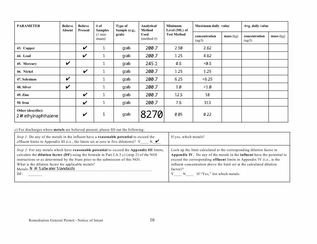
43. Copper
44. Lead
45. Mercury
46. Nickel
47. Selenium
48. Silver
49. Zinc
50. Iron
Other (describe):
c) For discharges where metals are believed present, please fill out the following:
Step 1: Do any of the metals in the influent have a reasonable potential to exceed the
effluent limits in Appendix III (i.e., the limits set at zero to five dilutions)? Y____ N____
If yes, which metals?
Step 2: For any metals which have reasonable potential to exceed the Appendix III limits,
calculate the dilution factor (DF) using the formula in Part I.A.3.c) (step 2) of the NOI
instructions or as determined by the State prior to the submission of this NOI.
What is the dilution factor for applicable metals?
Metals:_____________________________________________________________
DF: _______
Look up the limit calculated at the corresponding dilution factor in
Appendix IV. Do any of the metals in the influent have the potential to
exceed the corresponding effluent limits in Appendix IV (i.e., is the
influent concentration above the limit set at the calculated dilution
factor)?
Y____ N____ If “Yes,” list which metals:
Remediation General Permit - Notice of Intent 16

4. Treatment system information. Please describe the treatment system using separate sheets as necessary, including:
a) A description of the treatment system, including a schematic of the proposed or existing treatment system:
b) Identify each applicable
treatment unit (check all
that apply):
Frac. tank Air stripper Oil/water separator Equalization tanks Bag filter GAC filter
Chlorination Dechlorination Other (please describe):
c) Proposed average and maximum flow rates (gallons per minute) for the discharge and the design flow rate(s) (gallons per minute) of the treatment system:
Average flow rate of discharge__________ Maximum flow rate of treatment system ___________ Design flow rate of treatment system ___________
d) A description of chemical additives being used or planned to be used (attach MSDS sheets):
5. Receiving surface w ater(s). Please provide information about the receiving water(s), using separate sheets as necessary:
a) Identify the discharge pathway: Direct_____ Within facility__ Storm drain____ River/brook____ Wetlands_____ Other (describe):
b) Provide a narrative description of the discharge pathway, including the name(s) of the receiving waters:
c) Attach a detailed map(s) indicating the site location and location of the outfall to the receiving water:
1. For multiple discharges, number the discharges sequentially.
2. For indirect dischargers, indicate the location of the discharge to the indirect conveyance and the discharge to surface water
The map should also include the location and distance to the nearest sanitary sewer as well as the locus of nearby sensitive receptors (based on USGS topographical
mapping), such as surface waters, drinking water supplies, and wetland areas.
d) Provide the state water quality classification of the receiving water__________________________________,
e) Provide the reported or calculated seven day-ten year low flow (7Q 10) of the receiving water_________________________cfs
Please attach any calculation sheets used to support stream flow and dilution calculations.
f) Is the receiving water a listed 303(d) water quality impaired or limited water? Yes____ No____ If yes, for which pollutant(s)?
Is there a TMDL? Yes____ No____ If yes, for which pollutant(s)?
Remediation General Permit - Notice of Intent 17


Appendix B – Best Management Practices Plan

127 Hartwell Street, Suite 3 West Boylston, Massachusetts 01583 Tel: 774.450.7177 Fax: 888.835.0617 www.lrt-llc.net
BEST MANAGEMENT PRACTICES PLAN National Pollutant Discharge Elimination System – Remediation General Permit
Temporary Construction Dewatering East Pier, Building 7 – East Boston, Massachusetts
A Notice of Intent (NOI) for a Remediation General Permit (RGP) under the National Pollutant Discharge Elimination System (NPDES) has been submitted to the US Environmental Protection Agency (EPA) on behalf of the W.L. French Excavation Corporation (French) by Lockwood Remediation Technologies, LLC (LRT) in anticipation of temporary construction site dewatering planned to occur during proposed building construction at the above referenced job site (the Site). This Best Management Practices Plan (BMPP) was prepared in accordance with the general requirements of the NPDES RGP, and related guidance documentation provided by the EPA. The BMPP is included as Appendix B to the NOI and will be posted at the Site during the time of the work as specified in the NOI. Water Treatment and Management Construction dewatering will be conducted from either sumps or deep wells located inside the excavation. The treatment system will include a 21,000 gallon frac tank, pumps, filtration and options for carbon treatment, pH adjustment and cyanide treatment if necessary. This NOI has been prepared for the management of dewatering from the Site; please refer to Figure 1 Locus Plan for an overview of the immediate area surrounding the Site. The proposed work area, referred to as East Pier – Building 7, is depicted in Figure 2 along with the proposed discharge location adjacent to the Site. Discharge Monitoring and Compliance Routine Operation & Maintenance (O&M) will need to be completed on the water treatment system. Typical monitoring includes checking the flow of the system, routine bag filter changes and the collection of samples throughout the treatment system to verify the treatment system discharge is in compliance with the RGP. In the event that the system effluent is not within the discharge criteria of the RGP, modification to the treatment system may occur until discharge compliance can be consistently achieved. Please refer to Figure 3 for a layout of the proposed treatment system. The total monthly discharge will be monitored by a non-resettable flow meter and totalizer. Monthly monitoring reports will be compiled and maintained on site. Employees who have direct or indirect responsibility for enduring compliance with the RGP will be trained by the treatment system operator. Management of Treatment System Materials Potential sources of pollutants from the site include TSS, naturally occurring metals associated with the TSS, SVOCs and cyanide are anticipated during construction dewatering activities. Dewatering effluent will be pumped directly to the treatment system from the excavation via sumps and hoses to minimize handling. The general contractor at the site will establish staging areas away from the excavation and treatment system. Sediment collected in the frac tank used in the treatment system will be characterized

Notice of Intent – Remediation General Permit Page 2 East Pier – Building 7, East Boston, MA February 28, 2013 and disposed of as soil at an appropriate receiving facility in accordance with the applicable laws and regulations. Any used bag filters will be containerized and disposed of at an appropriate receiving facility. If the carbon treatment system is used, the granular activated carbon will be profiled and recycled at an approved receiving facility.

Appendix C – Laboratory Data

Page 1 of 7

Page 2 of 7

Page 3 of 7

Page 4 of 7

Page 5 of 7

Page 6 of 7

Page 7 of 7