East Mfg Parts Book - silvereaglemfg.com · Item SE Part Nbr Description . 1 2809 Eye, Sliding...
12
SILVER EAGLE MANUFACTURING COMPANY EAST MANUFACTURING OPERATION PROCEDURES PARTS LIST Model: CSL20N VIN: 0196 - 0225 Part Number: 15543 5825 NE Skyport Way Portland, Oregon 97218 (800) 547-6792 FAX (503) 335-2171
-
Upload
duongtuyen -
Category
Documents
-
view
217 -
download
0
Transcript of East Mfg Parts Book - silvereaglemfg.com · Item SE Part Nbr Description . 1 2809 Eye, Sliding...
SILVER EAGLE MANUFACTURING COMPANY
EAST MANUFACTURING
OPERATION PROCEDURES PARTS LIST
Model: CSL20N VIN: 0196 - 0225
Part Number: 15543
5825 NE Skyport Way Portland, Oregon 97218 (800) 547-6792 FAX (503) 335-2171
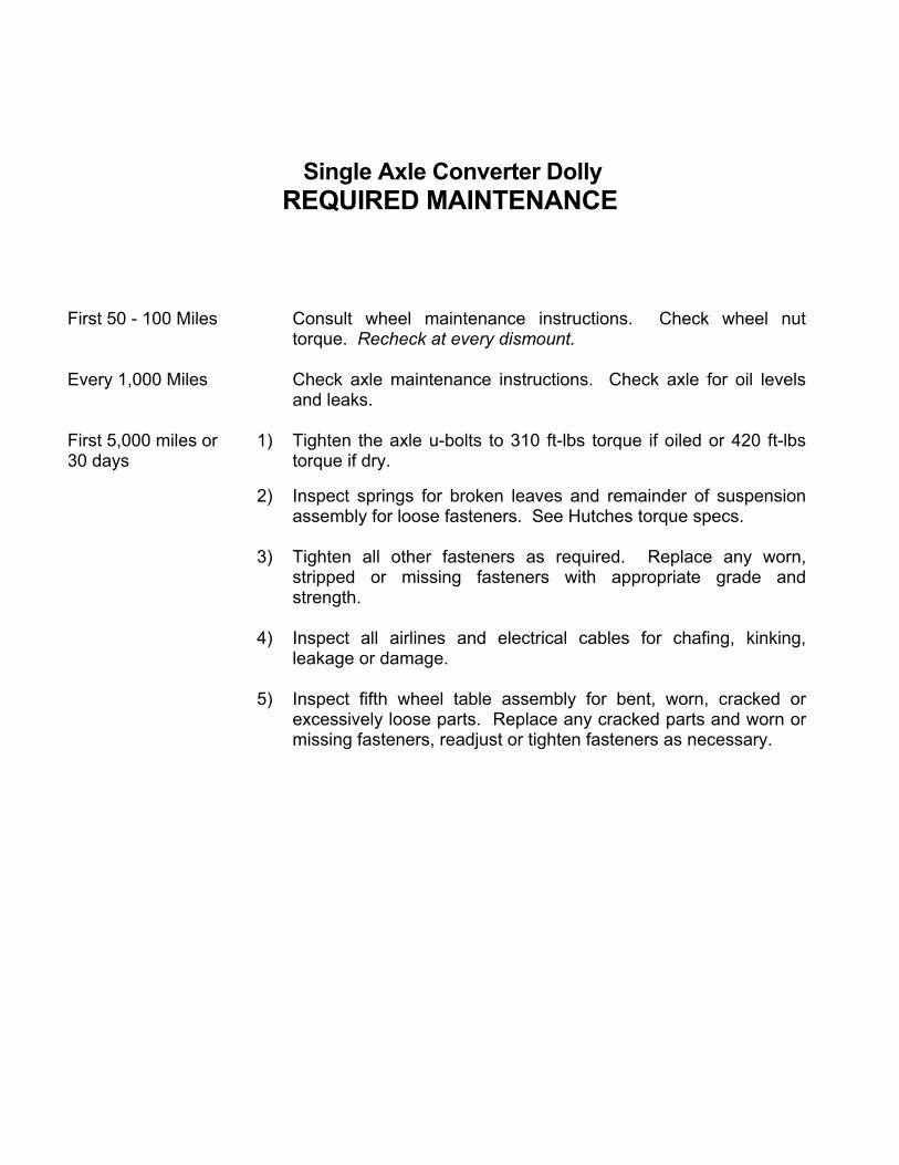
Single Axle Converter Dolly REQUIRED MAINTENANCE
First 50 - 100 Miles Consult wheel maintenance instructions. Check wheel nut torque. Recheck at every dismount.
Every 1,000 Miles Check axle maintenance instructions. Check axle for oil levels
and leaks. First 5,000 miles or 30 days
1) Tighten the axle u-bolts to 310 ft-lbs torque if oiled or 420 ft-lbs torque if dry.
2) Inspect springs for broken leaves and remainder of suspension assembly for loose fasteners. See Hutches torque specs.
3) Tighten all other fasteners as required. Replace any worn,
stripped or missing fasteners with appropriate grade and strength.
4) Inspect all airlines and electrical cables for chafing, kinking,
leakage or damage. 5) Inspect fifth wheel table assembly for bent, worn, cracked or
excessively loose parts. Replace any cracked parts and worn or missing fasteners, readjust or tighten fasteners as necessary.

Silver Eagle Fifth Wheel
OPERATING INSTRUCTIONS Coupling 1. Make sure jaw is locked open and trailer is at proper height. 2. Back dolly slowly under trailer until jaw locks kingpin and handle moves into the fifth wheel. Uncoupling 1. With vehicle at rest in a relaxed condition and landing gear down, (not being pushed together or pulled apart), pull fifth wheel handle outward and upward to lock the fifth wheel open. 2. Pull dolly slowly out from under the trailer. Note If the handle will not pull outward when the vehicle is in a relaxed condition, use landing gear to raise trailer and unload the dolly fifth wheel.
Contact Silver Eagle Customer Service for video tape on coupling and uncoupling twin/double trailers.

© 2000 Consolidated Metco, Inc.
SIMPLEX® SeriesFifth Wheels
05/2000
jmh
SIMPLEX Repair Kit Procedures

SIMPLEX® SERIESFIFTH WHEELS
JAW REMOVAL AND REPLACEMENT ON TRACTOR
SIMPLEX® SERIES FIFTH WHEELS
1
Figure 1
Figure 3
Figure 4
Figure 5
JAW / JAW PINDisassembly
1. Lock the jaw mechanism using a bar or block. (Figure 1)
CAUTION: The lock is spring loaded. Keep hands away from lock and jaw to avoid injury. Stand clear as the extended operating rod retracts rapidly during lockup.
2. Remove the clinch pincompletely remove the eccentric jaw pin. (Figures 2, 3 and 4)
3. Slide the jaw away from the lock and remove from the underside of the fifth wheel plate casting. (Figure 5)
Assembly
1. Clean and lubricate the fifth wheel plate jaw area and the replacement jaw.
2. Reassemble the parts in the reverse order of disassembly. NOTE: Position the eccentric jawpin with its arrow pointing to the arrow on the fifth wheel plate casting.
3. Reinstall the clinch pin.
4. Perform Steps 1 through 3 in the section“Jaw/Kingpin Clearance Adjustment”
Figure 2
jmh
(Figure 6, page 2) and
jmh
CAUTION:
FIFTH WHEELS
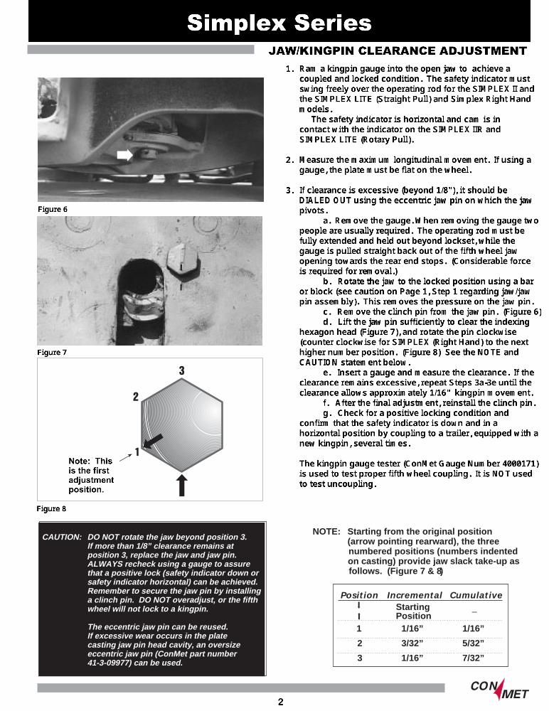
CAUTION: DO NOT rotate the jaw beyond position 3. If more than 1/8” clearance remains at position 3, replace the jaw and jaw pin. ALWAYS recheck using a gauge to assure that a positive lock (safety indicator down or safety indicator horizontal) can be achieved. Remember to secure the jaw pin by installing a clinch pin. DO NOT overadjust, or the fifth wheel will not lock to a kingpin.
The eccentric jaw pin can be reused. If excessive wear occurs in the plate casting jaw pin head cavity, an oversize eccentric jaw pin (ConMet part number41-3-09977) can be used.
NOTE: Starting from the original position (arrow pointing rearward), the three numbered positions (numbers indented on casting) provide jaw slack take-up as follows. (Figure 7 & 8)
Position Incremental CumulativeStarting –Position
1 1/16” 1/16”
2 3/32” 5/32”
3 1/16” 7/32”
jmh
Ram a kingpin gauge into the open jaw to achieve a coupled and locked condition. The safety indicator must swing freely over the operating rod for the SIMPLEX II and the SIMPLEX LITE (Straight Pull) and Simplex Right Hand models. The safety indicator is horizontal and cam is in contact with the indicator on the SIMPLEX IIR and SIMPLEX LITE (Rotary Pull). Measure the maximum longitudinal movement. If using a gauge, the plate must be flat on the wheel. If clearance is excessive (beyond 1/8"), it should be DIALED OUT using the eccentric jaw pin on which the jaw pivots. a. Remove the gauge. When removing the gauge two people are usually required. The operating rod must be fully extended and held out beyond lockset, while the gauge is pulled straight back out of the fifth wheel jaw opening towards the rear end stops. (Considerable force is required for removal.) b. Rotate the jaw to the locked position using a bar or block (see caution on Page 1, Step 1 regarding jaw/jaw pin assembly). This removes the pressure on the jaw pin. c. Remove the clinch pin from the jaw pin. (Figure 6) d. Lift the jaw pin sufficiently to clear the indexing hexagon head (Figure 7), and rotate the pin clockwise (counter clockwise for SIMPLEX (Right Hand) to the next higher number position. (Figure 8) See the NOTE and CAUTION statement below. e. Insert a gauge and measure the clearance. If the clearance remains excessive, repeat Steps 3a-3e until the clearance allows approximately 1/16" kingpin movement. f. After the final adjustment, reinstall the clinch pin. g. Check for a positive locking condition and confirm that the safety indicator is down and in a horizontal position by coupling to a trailer, equipped with a new kingpin, several times. The kingpin gauge tester (ConMet Gauge Number 4000171) is used to test proper fifth wheel coupling. It is NOT used to test uncoupling.
jmh
jmh
jmh
jmh
jmh
Simplex Series
jmh
Note: This is the first adjustment position.
jmh
Note:
jmh
jmh
1. 2. 3.
jmh
jmh
jmh
jmh
jmh
JAW/KINGPIN CLEARANCE ADJUSTMENT
jmh
Figure 6
jmh
Figure 8
jmh
Figure 7
jmh
2
jmh
CAUTION:
SIMPLEX® SERIESFIFTH WHEELS
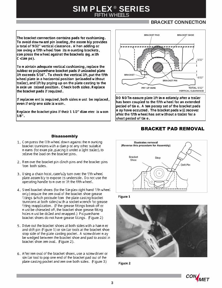
BRACKET CONNECTION
3
BRACKET PAD BRACKET SHOE
BRACKET
BRACKET PIN
PRY UP HERE
3/32"
6/32"
TOTAL 9/32"VERTICAL CLEARANCE
jmh
The bracket connection contains pads for cushioning. To avoid downward pin loading, the assembly provides a total of 9/32” vertical clearance. When adding or removing a fifth wheel from its mounting brackets, compress the wheel against the brackets (eg. with C-clamps). To maintain adequate vertical cushioning, replace the rubber or polyurethane bracket pads if unloaded plate lift exceeds 5/16”. To check the vertical lift, put the fifth wheel plate in a horizontal position (unloaded without trailer), and lift by prying up on the plate casting to the maximum raised position. Check both sides. Replace the bracket pads if required. If replacement is required, both sides must be replaced, even if only one side is worn. Replace the bracket pins if their 1 1/2” diameter is worn 1/8”.
jmh
jmh
DO NOTmeasure plate lift immediately after a trailer has been coupled to the fifth wheel for an extended period of time. A temporary set of the bracket pads may have occurred. The bracket pads will recover after the fifth wheel has set without a trailer for a short period of time.
jmh
jmh
BRACKET PAD REMOVAL
jmh
Bracket Shoe
jmh
Drift Pin
jmh
Stop
jmh
Illustrates removal (Reverse this procedure for Assembly)
jmh
Disassembly
jmh
Compress the fifth wheel down against the mounting bracket trunnions with a clamp or any other suitable means (for example, placing it under a light trailer), to relieve the load on the bracket pins. Remove the bracket pin clinch pins and the bracket pins from both sides. Using a chain hoist, carefully turn over the fifth wheel plate assembly to expose its underside. Do not use the operating handle to move or lift the fifth wheel. Steel bracket shoes (for the Simplex right hand fifth wheel only) require the removal of the bracket shoe grease fittings (which protrude from the plate casting bracket trunnions at both sides) with a socket wrench for grease fitting reapplication. (If the grease fittings break off or must be chieseled off, the bracket shoe grease fitting holes must be drilled and retapped.) Polyurethane bracket shoes do not have grease fittings. (Figure 2) Drive out the bracket shoes at both sides with a hammer and drift pin (Figure 1) or similar tools at the bracket shoe stop side of the plate casting pocket. A screwdriver may be wedged between the bracket shoe and pad to assist in bracket shoe removal. (Figure 2). After removal of the bracket shoes, use a screwdriver or similar tool to pop one end of the bracket pad out of the plate casting pocket and remove both sides. (Figure 3)
jmh
1. 2. 3. 4. 5. 6.
jmh
Figure 1
jmh
Figure 2

SIMPLEX® SERIESFIFTH WHEELS
BRACKET PAD REPLACEMENT
SIMPLEX® SERIESFIFTH WHEELS
4
COVER PLATE
CLINCH PIN
BRACKET PIN
CLINCH PIN
BRACKET PINHUMP
LONG STRAIGHT LEG
COVER PLATE
CLINCH PIN
BRACKET PIN
CLINCH PIN
BRACKET PINHUMP
SHORT LEG
COVER PLATE
CLINCH PIN
BRACKET PIN
CLINCH PIN
BRACKET PINHUMP
SHORT LEG
jmh
Install the new bracket pads. It may be necessary to use a block and hammer to tap the bracket pads completely into the plate casting pocket until reaching the end stops. The bracket pad cutouts face outward and the raised "shoe side" letters go against the bracket shoe. (There are no cutouts on the bracket pads for SIMPLEX Right Hand Fifth Wheels.) For steel bracket shoes and rubber bracket pads, apply a liquid soap detergent or similar liquid medium to the bracket pad and bracket shoe interface for ease of application. Drive the bracket shoes in place against the plate casting bracket shoe end stops using a hammer (Figure 5) For steel bracket shoe applications (Simplex Right Hand only), replace the removed grease fittings or apply new grease fittings into the bracket shoes at the plate casing bracket trunnions on both sides. Lubricate the interface of the steel bracket shoe and the mounting bracket trunnion on both sides of the fifth wheel. Lubrication is not required for polyurethane bracket shoe applications. Using a chain hoist, carefully turn over the fifth wheel plate assembly and position it on the mounting bracket trunnions. Compress the fifth wheel downward against the mounting bracket trunnions with a clamp or any other suitable means (for example, placing it under a light trailer), and install the bracket pins at both sides. Install the bracket pin clinch pins in both bracket pins. The clinch pins must not be jammed against the cover plate or casting. (See Below)
jmh
1. 2. 3. 4. 5. 6. 7. 8.
jmh
Warning: Do not apply grease or oil to the backet pad surfaces or the plate casting pocket and bracket shoe interface surfaces. A liquid soap detergent or similar liquid medium is acceptable.
jmh
Old design with short clinch pin leg
jmh
New design with long straight clinch pin leg
jmh
New design
jmh
Old design
jmh
LONG STRAIGHT LEG SHORT LEG
jmh
Warning:
jmh
Figure 3
jmh
Figure 4
jmh
Figure 5
jmh
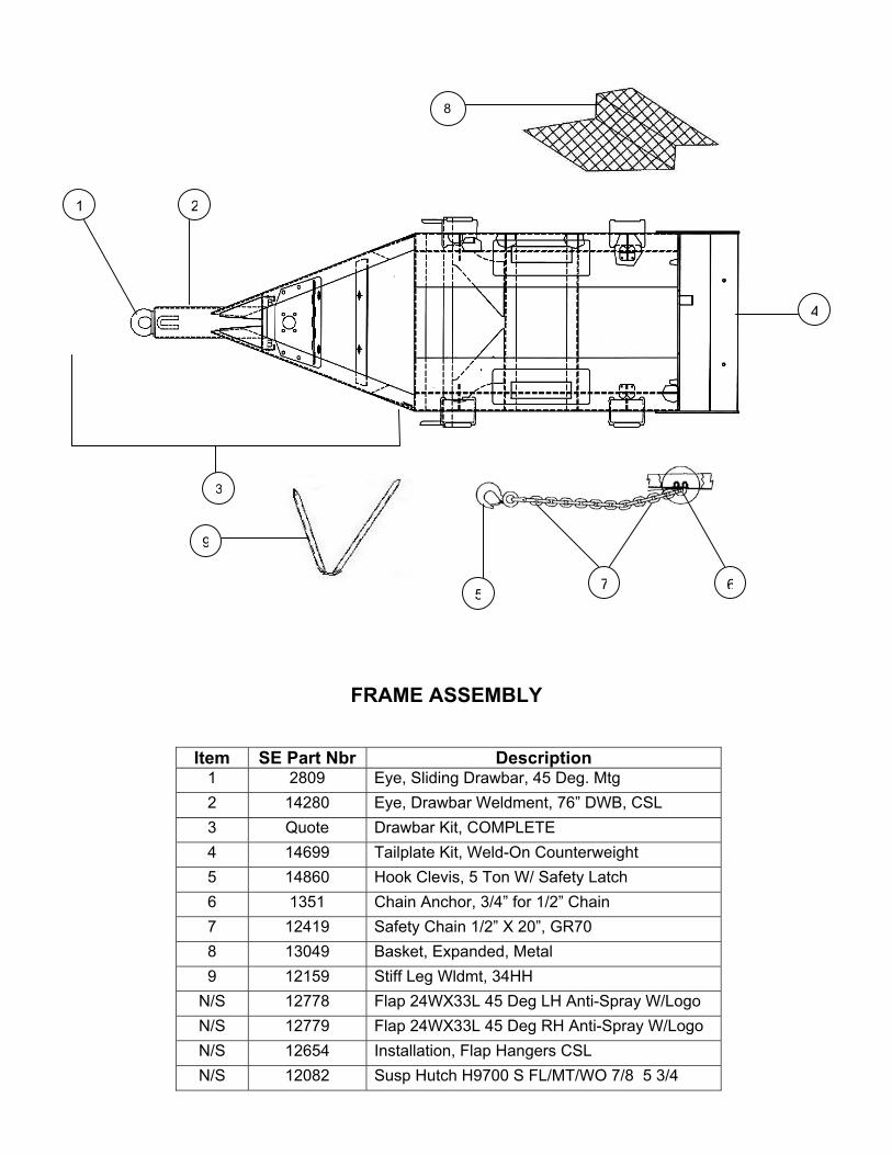
FRAME ASSEMBLY
Item SE Part Nbr Description
1 2809 Eye, Sliding Drawbar, 45 Deg. Mtg 2 14280 Eye, Drawbar Weldment, 76” DWB, CSL 3 Quote Drawbar Kit, COMPLETE 4 14699 Tailplate Kit, Weld-On Counterweight 5 14860 Hook Clevis, 5 Ton W/ Safety Latch 6 1351 Chain Anchor, 3/4” for 1/2” Chain 7 12419 Safety Chain 1/2” X 20”, GR70 8 13049 Basket, Expanded, Metal 9 12159 Stiff Leg Wldmt, 34HH
N/S 12778 Flap 24WX33L 45 Deg LH Anti-Spray W/Logo N/S 12779 Flap 24WX33L 45 Deg RH Anti-Spray W/Logo N/S 12654 Installation, Flap Hangers CSL N/S 12082 Susp Hutch H9700 S FL/MT/WO 7/8 5 3/4
3
2
5
1
4
7 6
8
9

AIR SYSTEM
Item SE Part Nbr Description 1 2414 Air Reservoir Assy 2 1278 Valve, Push-Pull, PP-1 3 13738 Valve, Relay/ABS Control Meritor/WABCO, PLC 4 10748 Valve, Check, 90 Deg Style 5 9857 Valve, Control Line 6 12582 Valve, Pressure Protection 7 9858 Valve, Emergeny Control 8 5855 Glandhand, Emergency, W/Full Face Red Seal 9 5854 Glandhand, Service, W/Full Face Blue Seal
10 14926 Hose, Air, 3/8 X 92, Rubber, 3/8 X ½ Conn 11 11222 Hose, Air, 3/8 X 37, Rubber, 3/8 X3/8 Conn NS 1775 Valve, Drain, Lever
2
3
45
6
7
3
8
9
10
11

ELECTRICAL SYSTEM
Item SE Part Nbr Description 1 10319 Cable 7-Way Straight 10’ W/Plugs ABS 2 12514 Harness ABS, 2-Socket, 2-Light 3 9562 Lens, Amber, Trucklite, ABS 4 9563 Grommet, Lamp, Trucklite, Model 30 5 2508 Lamp, Red, Grote, (Lamp Only) 6 2509 Grommet, Lamp, Grote 7 2652 Capscrew, 5/16-18 UNC X 1-1/4, HX, GR 5, PTD 8 1646 Nut, 5/16-18 UNC, NYL INS, HEX, PTD 9 1454 Washer, 5/16, SAE, PTD
1
2
3 456
9 8 7

FIFTHWHEEL
Item SE Part Nbr Description 1 104-4-02700 5TH Wheel Simplex Lite LH Release
AXLE ASSEMBLY
Item SE Part Nbr Description N/S 15544W Axle Assy 71.5 Cast A5.5M ABS 5/8 Wall
1