
earthquake table inst#4F594Ceducation.jlab.org/workbench/earthquake/earthquake.pdf · earthquake in...
16
Thomas Jefferson National Accelerator Facility - Office of Science Education Shake, Rattle and Roll An Earthquake Simulation Table
Transcript of earthquake table inst#4F594Ceducation.jlab.org/workbench/earthquake/earthquake.pdf · earthquake in...

Thomas Jefferson National Accelerator Facility - Offi ce of Science Education
Shake, Rattle and RollAn Earthquake Simulation Table

An Earthquake Simulation Table http://education.jlab.org/workbench/
An Earthquake Simulation TableBackground
Designing buildings that can withstand the violent motions of the earth during an earthquake is important in geologically active areas. It can, however, be highly inconvenient to wait for an actual earthquake in order to test a building's design. This small, electrically powered table can simulate the motion of an earthquake so that design ideas can be tested.
OverviewThe Earthquake Simulation Table consists of a base section and a moveable top plate. A motor attached
to the base forces the top plate to slide back and forth. The rate at which the top plate moves can be controlled by adjusting a potentiometer or by adjusting the point of contact between the motor and top plate.
The motor used in this project is a geared motor that is rated at 120 revolutions per minute at 12 volts while under no load. The physical dimensions of the motor dictated the height of the base. You may need to adjust the height of the base to fi t the motor you use. Also, the aluminum cam is sized for our particular motor. Once again, alterations may be necessary for it to fi t your particular motor.
Component List5/8" thick particle board (roughly 3 1/2 square feet needed)1/4" thick plywood (roughly 1 1/2 square feet needed)7/8" diameter Tefl on furniture glides (4 needed)fi berglass reinforced Tefl on tape (roughly 3 feet needed)2" long, coarse thread drywall screws (12 needed)12 volt geared DC motor (1 needed)24 volt power supply with 2.1 mm diameter output plug (1 needed)2.1 mm panel mount power jack (1 needed)50 ohm, 5 watt wirewound potentiometer (1 needed)1/2" diameter knob to fi t 50 ohm, 5 watt potentiometer (1 needed)SPST toggle switch (1 needed)aluminum fl ange as per Appendix C (1 needed)aluminum cam as per Appendix D (1 needed)#6-32 × 2" aluminum hex standoff (3 needed)#6-32 × 3/4" machine screw (3 needed)#6-32 × 3/8" machine screw (3 needed)#8-32 × 3/16" set screw (2 needed)#10-32 × 3/4" machine screw (1 needed)#10-32 × 5/8" fl at head phillips machine screw (4 needed)#10-32 × 1/2" cylindrical standoff with an outer diameter of 1/4" (1 needed)20 gauge stranded hook-up wire (roughly 2 feet needed)1/8" diameter heat shrink (roughly 4 inches needed)adhesive feet (4 needed)wood glue

An Earthquake Simulation Table http://education.jlab.org/workbench/
All of the components have been gathered. All of the wood has been cut and all necessary holes have been drilled.

An Earthquake Simulation Table http://education.jlab.org/workbench/
Bottom Plate Preparation 1. Cut one square piece of 5/8" thick particle board that measures 10 12/32" on a side. 2. Measure, mark and drill any holes which are necessary for attaching the motor to the bottom plate.
The motor should be mounted so that its axis of rotation is located at the center of the bottom plate. For the particular device illustrated within this document, three 9/64" diameter holes were drilled in the bottom plate to accommodate three #6-32 machine screws.
3. Drill twelve 9/64" diameter pilot holes around the perimeter of the bottom plate, three along each edge. The center of each pilot hole should be located 5/16" away from its respective edge and spaced so that one pilot hole is centered on its respective edge while the other two pilot are located 2" from the ends of the plate.
4. Countersink each pilot hole, as well as any holes needed for mounting the motor, on the bottom surface of the bottom plate.
Pilot holes have been drilled around the perimeter of the base plate and mountingholes for the motor have been drilled near the center of the base plate.
5. The bottom plate is now complete.

An Earthquake Simulation Table http://education.jlab.org/workbench/
Side Plate Preparation 1. Cut four sections of 5/8" thick particle board that each measure 3 25/32" wide by 10 12/32" long.
Miter cut both short ends of all four pieces to a 45˚ angle.
One of the four side plates.
2. Drill two 5/64" diameter pilot holes along the top edge of two of the four side plates. The pilot holes should be centered along the width of each of the side plates and located about 5/8" from each end.
Two 5/64" diameter pilot holes have been drilled in the top edge of one of the side plates.
3. Choose one of the two side plates with pilot holes to be the Earthquake Simulation Table's control panel. Drill holes for the wirewound potentiometer, power switch and power jack as necessary. You can use the drill pattern found in Appendix A as a general guide, but the exact dimensions and locations of the holes in your device will depend on the parts you were able to obtain.
From left to right, mounting holes for the wirewound potentiometer, power switchand power jack have been drilled in one of the side plates.
4. The side plates are now ready!

An Earthquake Simulation Table http://education.jlab.org/workbench/
Top Plate Preparation 1. Cut a section of 1/4" thick plywood that measures 12" wide by 14" long. 2. Drill four 13/64" diameter holes in the 12" × 14" plywood piece to accept the #10-32 × 5/8" fl at
head phillips machine screws. The screws will be used to attach the aluminum fl ange to the top plate. The screw holes must be positioned so that the aluminum fl ange is centered on the plywood piece with the fl ange's long axis aligned with the plywood piece's short axis.
3. Countersink the four screw holes on the top surface of the plywood piece.
Holes for mounting the aluminum fl ange to the top plate have been drilled and countersunk.
4. Cut four pieces of 5/8" thick particle board that each measure 1 1/2" wide by 14" long. Two of these pieces will be used with the top plate while the other two pieces will be attached to the base to provide anchor points so that the device can be clamped to a desk or table.
5. All pieces for the top plate are now ready. We can now begin assembly!
An Earthquake Simulation Table http://education.jlab.org/workbench/
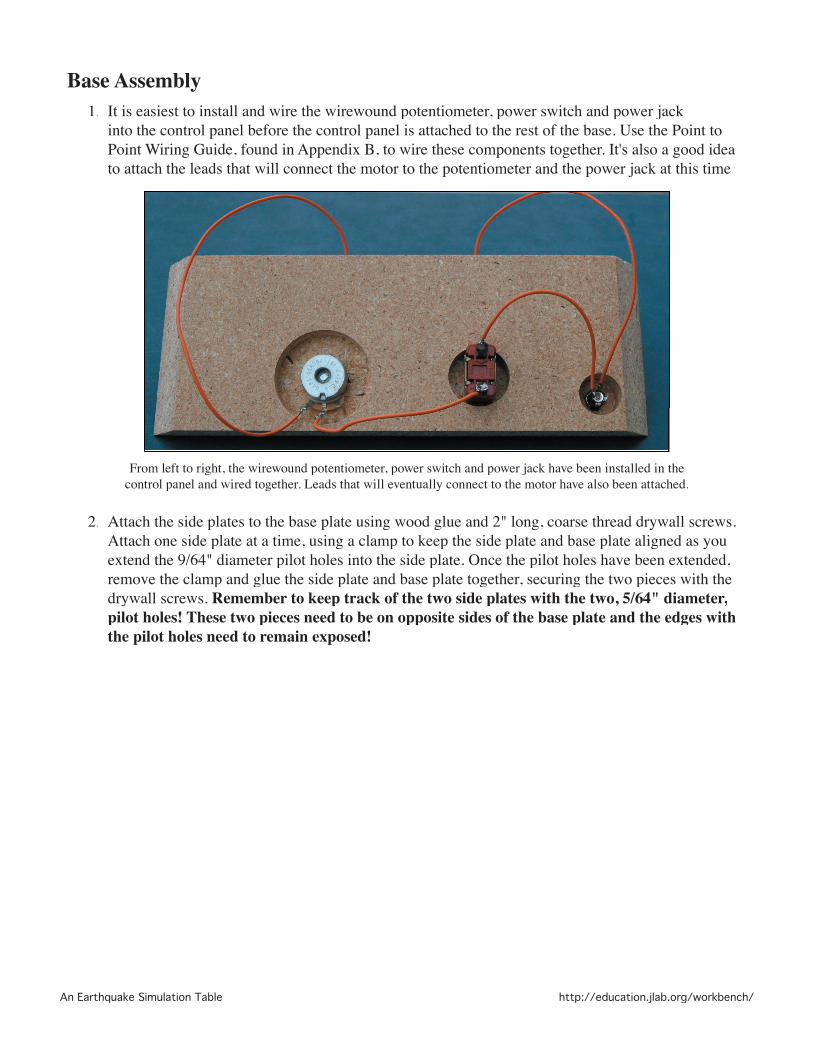
Base Assembly1. It is easiest to install and wire the wirewound potentiometer, power switch and power jack
into the control panel before the control panel is attached to the rest of the base. Use the Point to Point Wiring Guide, found in Appendix B, to wire these components together. It's also a good idea to attach the leads that will connect the motor to the potentiometer and the power jack at this time.
From left to right, the wirewound potentiometer, power switch and power jack have been installed in thecontrol panel and wired together. Leads that will eventually connect to the motor have also been attached.
2. Attach the side plates to the base plate using wood glue and 2" long, coarse thread drywall screws. Attach one side plate at a time, using a clamp to keep the side plate and base plate aligned as you extend the 9/64" diameter pilot holes into the side plate. Once the pilot holes have been extended, remove the clamp and glue the side plate and base plate together, securing the two pieces with the drywall screws. Remember to keep track of the two side plates with the two, 5/64" diameter, pilot holes! These two pieces need to be on opposite sides of the base plate and the edges with the pilot holes need to remain exposed!

An Earthquake Simulation Table http://education.jlab.org/workbench/
3. Insert a Tefl on furniture glide into each of the four 5/64" pilot holes.
All four side plates have been attached to the base and four Tefl onfurniture glides have been placed in their pilot holes.
4. Attach the aluminum cam to the motor's axle by tightening the two set screws.
The aluminum cam has been attached to the motor.

An Earthquake Simulation Table http://education.jlab.org/workbench/
5. Thread the #10-32 × 3/4" machine screw through one of the aluminum cam's threaded holes so that the screw's shaft extends away from the motor. The screw only needs to be tightened to fi nger tightness.
A screw has been threaded into one of the aluminum cam's holes.
6. Thread the #10-32 × 1/2" cylindrical standoff onto the exposed end of the #10-32 × 3/4" machine screw. The cylindrical standoff only needs to be tightened to fi nger tightness.
The cylindrical standoff has been threaded onto the screw shaft.

An Earthquake Simulation Table http://education.jlab.org/workbench/
7. Mount the motor to the base board. For the particular device illustrated within this document, the motor was mounted to three, 2" long, aluminum hex standoffs using three #6-32 × 3/8" machine screws. The aluminum hex standoffs were then mounted to the base using three #6-32 × 3/4" machine screws.
The motor was attached to the base using three 2" long standoffs, three 3/8" longmachine screws (from above) and three 3/4" long machine screws (from below).
8. Connect the leads from the potentiometer and the power jack to the motor. Cover any exposed wire with heat shrink. Ideally, the motor will spin counterclockwise when it is turned on.
9. Glue two of the 1 1/2" wide by 14" long pieces of particle board to the bottom of the base board. These two pieces can be arranged in whichever manner is the most convenient for your particular set-up.
10. Attach four adhesive feet to the bottom of the base.11. The base is now complete!
An Earthquake Simulation Table http://education.jlab.org/workbench/
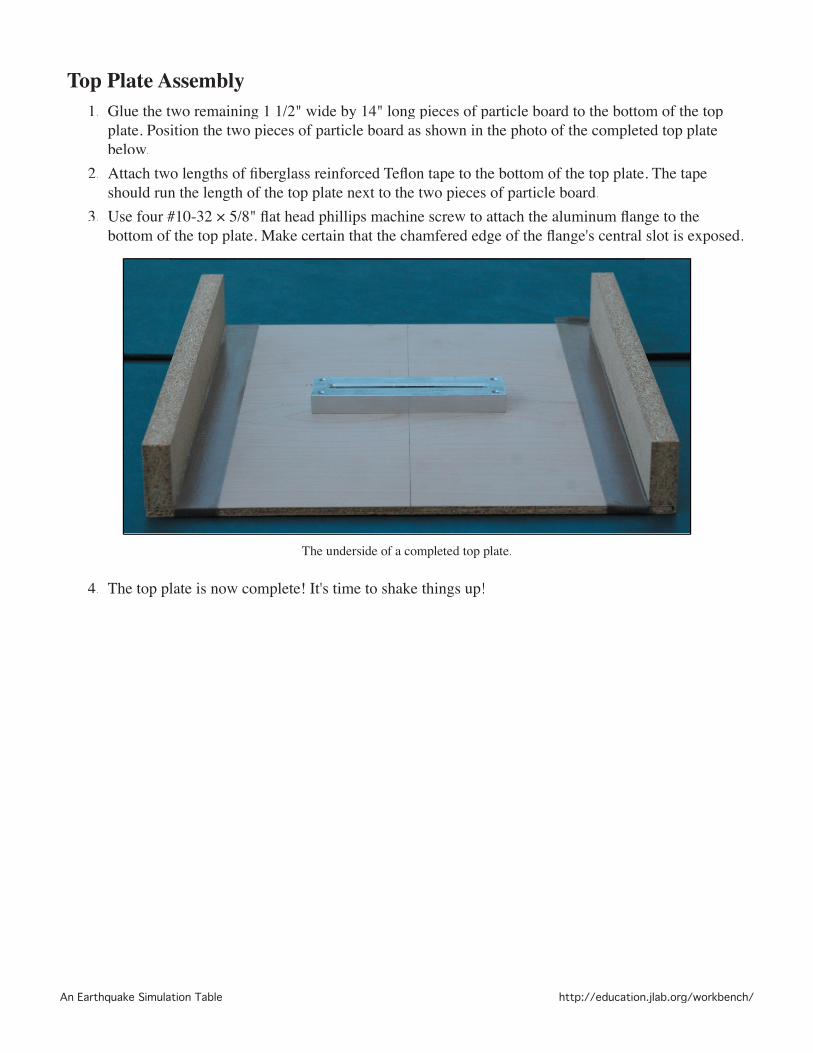
Top Plate Assembly 1. Glue the two remaining 1 1/2" wide by 14" long pieces of particle board to the bottom of the top
plate. Position the two pieces of particle board as shown in the photo of the completed top plate below.
2. Attach two lengths of fi berglass reinforced Tefl on tape to the bottom of the top plate. The tape should run the length of the top plate next to the two pieces of particle board.
3. Use four #10-32 × 5/8" fl at head phillips machine screw to attach the aluminum fl ange to the bottom of the top plate. Make certain that the chamfered edge of the fl ange's central slot is exposed.
The underside of a completed top plate.
4. The top plate is now complete! It's time to shake things up!

An Earthquake Simulation Table http://education.jlab.org/workbench/
Operation 1. Place the top plate on the base so that the cylindrical standoff attached to the aluminum cam
engages the slot in the aluminum fl ange.
A cutaway view showing the cylindrical standoff engaging the aluminum fl ange.
2. Plug the power supply into the power jack and turn the power switch on. The top plate should slide back and forth along the top of the base. Thanks to Newton and his wonderful laws of motion, the base will move in response to the movement of the top plate. It's helpful to clamp the device to the table it is sitting on to minimize this motion.
3. The speed of the top plate's movement can be controlled by adjusting the potentiometer or by moving the #10-32 screw in the aluminum cam to a different threaded hole.

An Earthquake Simulation Table http://education.jlab.org/workbench/
Appendix A - Control Panel Drill Pattern
���
��
�����
���������
���������
���������
����
�
����
����
����
��
��
����
1.000"
An Earthquake Simulation Table http://education.jlab.org/workbench/
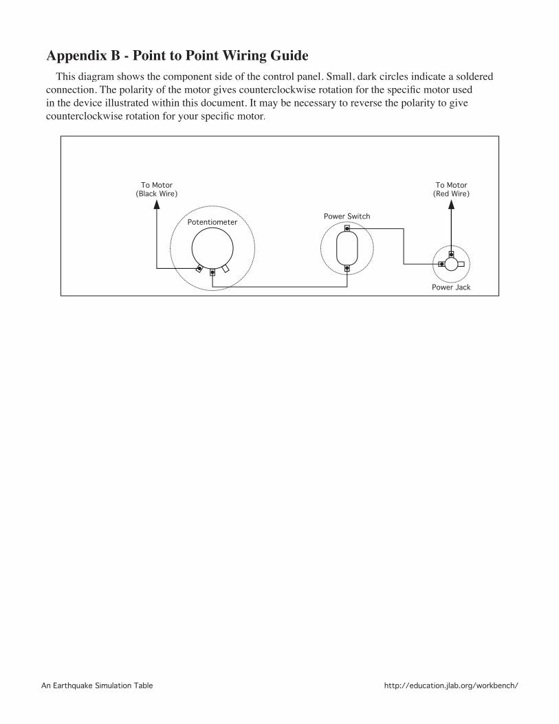
Appendix B - Point to Point Wiring GuideThis diagram shows the component side of the control panel. Small, dark circles indicate a soldered
connection. The polarity of the motor gives counterclockwise rotation for the specifi c motor used in the device illustrated within this document. It may be necessary to reverse the polarity to give counterclockwise rotation for your specifi c motor.
Power Jack
Power SwitchPotentiometer
To Motor(Red Wire)
To Motor(Black Wire)

An Earthquake Simulation Table http://education.jlab.org/workbench/
Appendix C - Flange Mechanical Drawing
An Earthquake Simulation Table http://education.jlab.org/workbench/
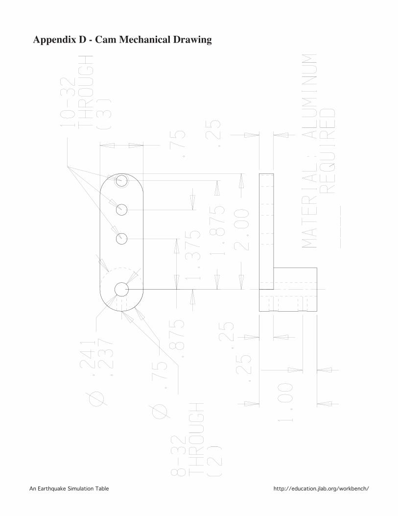
Appendix D - Cam Mechanical Drawing