Earth Resistance and Calculation of...
27
University of Ljubljana Faculty of Electrical Engineering Earth Resistance and Calculation of Earthing Seminar paper at subject Distribution and Industrial Systems Student: Rajne Ilievska Mentor: Prof. dr. Grega Bizjak Study year 2017/ 2018 Ljubljana
Transcript of Earth Resistance and Calculation of...

University of Ljubljana
Faculty of Electrical Engineering
Earth Resistance and Calculation of Earthing
Seminar paper at subject
Distribution and Industrial Systems
Student: Rajne Ilievska
Mentor: Prof. dr. Grega Bizjak
Study year 2017/ 2018
Ljubljana

University of Ljubljana - Faculty of Electrical Engineering Rajne Ilievska Laboratory of Lighting and Photometry Power Distribution and Industrial Systems __________________________________________________________________________________________
2
Contents
1. Introduction ........................................................................................................................................ 4
1.1 Basic concepts of earthing ............................................................................................................ 4
2. Specific resistance of the soil .............................................................................................................. 6
2.1 Moisture content in the earth soil ................................................................................................ 7
2.2 Temperature of the ground .......................................................................................................... 7
2.3 Salinity of soil ................................................................................................................................ 8
2.4 Compaction of the ground ............................................................................................................ 8
3. Measuring the specific soil resistance ................................................................................................ 9
3.1 Wenner method .......................................................................................................................... 10
3.1.1 Calculation of soil resistivity ................................................................................................ 11
3.2 Schlumberger method ................................................................................................................ 13
3.3 Implementation of the measurement ........................................................................................ 13
4. Interpretation of the results ............................................................................................................. 14
5. Types of earthing .............................................................................................................................. 16
5.1 Materials of the earthing electrodes and application ................................................................ 17
6. Measurement and calculation of earthing ....................................................................................... 17
6.1 Measurement .............................................................................................................................. 17
6.2 Calculation .................................................................................................................................. 21
7. Impulse resistance ............................................................................................................................ 22
8. Conclusion ......................................................................................................................................... 25
9. Questions .......................................................................................................................................... 25
10. Calculation example ........................................................................................................................ 26
References ............................................................................................................................................ 27

University of Ljubljana - Faculty of Electrical Engineering Rajne Ilievska Laboratory of Lighting and Photometry Power Distribution and Industrial Systems __________________________________________________________________________________________
3
ABSTRACT
In power systems one of the most important aspect is the earthing in order to protect
the people and the equipment in case of an electrical fault. This seminar paper aims to present
a general overview of the main parameters and calculations in an earthing system. In order
to calculate the required parameters, a measurement of the soil resistivity is necessary. In the
first part of the seminar paper is described what is soil resistivity, what affects on it, which
are the characteristic values of the resistivity of different soils, how it is calculated or
measured. The second part of the seminar paper gives information for the types of earthing
electrodes that are used in an earthing system and how the resistance of the earthing
electrode is measured or calculated.
Key words: earthing, soil resistivity, earthing electrodes, measurement, calculation

University of Ljubljana - Faculty of Electrical Engineering Rajne Ilievska Laboratory of Lighting and Photometry Power Distribution and Industrial Systems __________________________________________________________________________________________
4
1. Introduction
1.1 Basic concepts of earthing
The term earthing in power system refers to a conductive connection between metal
parts of an installation in a building, or power plant, which can under any circumstances be
under voltage, and the earth through an earthing electrode. The main part of an earthing
system is the earthing electrode set in the ground, and its primary task is to conduct the so
called ''current of error'', or current from atmospheric discharge, in such a way that the earth
will not be exposed to voltages that would put people in danger in the immediate
surrounding. In case of large faults in a transformer substation or overhead steel supports,
at the place of error the potential rises, sometimes reaching values of several kilovolts. By
flowing the current through an earthing electrode into the ground the potential of the ground
rises. The ‘earth potential rise’ is highest at the point where current enters the ground and
declines with distance from the source. The shape and spacing of the equipotential lines
around the earthing electrode depends of the shape of earthing electrode, the size of the
current and the specific soil resistivity [3].
When designing an earthing system, two voltages characterise the criteria for safety
around the installation: touch voltage and step voltage. The ‘touch voltage’ is the potential
difference between the earth potential rise on a structure and the surface potential at a point
where a person is standing (normally 1m), whilst at the same time having one or both hands
in contact with the structure. The ‘step voltage’ is the difference in surface potential
experienced by a person bridging a distance of 1m with their feet [4]. The allowed values for
touch voltage and step voltage depending on the duration of the current flow through the
earthing system are defined with technical regulation in each country according to different
standards. Also, there are different values for touch and step voltages depending on the place
where the fault occurs, in or out of the plant [3]. For providing safe operation touch voltage
and step voltage should be lower that the allowed values.
Picture 1 Step voltage and touch voltage

University of Ljubljana - Faculty of Electrical Engineering Rajne Ilievska Laboratory of Lighting and Photometry Power Distribution and Industrial Systems __________________________________________________________________________________________
5
All the parameters that are important in an earthing system, touch voltage, step
voltage, distribution of the potential, the resistance of the earthing electrode, depend on the
dimension and configuration of the electrode and the specific resistance of the soil where it
is set. The resistance of the earthing is the transient resistance between the earth electrode
and the soil, the resistance of the electrode, the resistance of the conductor that bonds the
objects and the earth electrode, in dependence of the resistance of the soil. It is defined as a
ratio between the potential of the earthing electrode and the current that flows through:
𝑅𝑒 =𝜑
𝐼=
𝑈
𝐼
This resistance is known as resistance to propagation. In addition to this parameter, there is
also impedance Z of an earthing system, that is defined as a parallel impedance of all the
earthing resistances connected in the earthing system including overhead lines, cables, as
well as pipelines and water supply lines that are also connected in the earthing system [1].
In order to calculate the required earthing parameters, it is necessary to measure the soil
resistivity. After the measurements and the calculation of the parameters, the results are
compared to the tolerable voltage limits that should be met.

University of Ljubljana - Faculty of Electrical Engineering Rajne Ilievska Laboratory of Lighting and Photometry Power Distribution and Industrial Systems __________________________________________________________________________________________
6
2. Specific resistance of the soil
The earth’s soil has an electric property – earth resistance to the flow of electric
current. This property shows how much the soil resists the flow of electricity. It is important
parameter when designing an earthing system. In most of the cases very strict requirements
are set for the characteristics of the earthing parameters: soil resistance, touch voltage, step
voltage when taking the current of the error, so it is necessary that they are calculated as
accurately as possible. The earthing resistance depends from the specific earth resistance of
the soil where the earth electrode is placed. The earth’s soil resistance varies in wide range
of values, depending on the composition of the ground. However, the soil resistance is not a
constant value, it varies depending on the conditions or with depth. The temperature, the
quantity of the water in the pores of the earth, the amount of salts dissolved in the water,
they all have an impact of the values of earth’s soil resistance [1]. In fact, the saline solution
is an electrolyte that fills the space between particles of the earth and conducts the electric
current in the ground. According to this, the soils that have many pores, for example marl and
some types of clays, have small values for the specific earth resistance. On the other hand,
the soils with small amount of pores, such as limestone or dolomites, have high values for the
specific earth resistance. In the table below are given the approximate values of the specific
earth resistance for different types of earth soil.
Table 1 Specific soil resistance for different composition of the soil
Type of environment, composition of the soil
Specific earth resistance – ρ [Ωm]
Sea water 1
Distilled water 10000
Water from river 20 – 40
Wetland 30
Cracked limestone 200 – 2000
Sand 100 – 800
Marl 20 – 300
Clay 100
Humus soil 100
Dolomit 200 – 10000
Concrete 1000000
Granite 600 – 10000
Moist sand 200
Gravel 2000 – 6000
Rocky ground 3000
Sandy clay 50 – 60
Marble >5000
Bentonite 2 – 8

University of Ljubljana - Faculty of Electrical Engineering Rajne Ilievska Laboratory of Lighting and Photometry Power Distribution and Industrial Systems __________________________________________________________________________________________
7
From the values given in the table it is shown that different composition of the earth affects
its resistance. Among the best conductivity have wetlands, clay and soil with metal content.
Most unfavourable is stone-based soil. However, the soil is usually composed of several layers
with different composition and in rare cases there is homogenous composition.
2.1 Moisture content in the earth soil
Soil moisture changes seasonally and has different content according to the depth. In
the periods when the months are rainy the specific resistance has lower values and in periods
with no rain the values are higher. When the earth is dry it is a weak conductor, or in other
words by reducing moisture content the resistance increases [2]. The states when the earth
is dry or frozen are dangerous because then the specific resistance has the greatest values.
On the figure below is shown the dependence of the specific resistance of the earth from
humidity. As shown, the specific resistance is significantly greater if the relative humidty is
below 15%. For humidity over 15% the specific resistance is much lower and changes in
resistance with change of humidity are milder.
Picture 2 Dependence of the soil resistivity from the moisture content in the soil
2.2 Temperature of the ground
The temperature of the ground is a significant factor affecting the value of the specific
resistance of the earth. At the same level of humidity of the earth with increasing the
temperature the resistance decreases. By freezing the water in earth the resistance increases
significantly. In order to avoid this undesirable occurrence the earthing should be set at depth
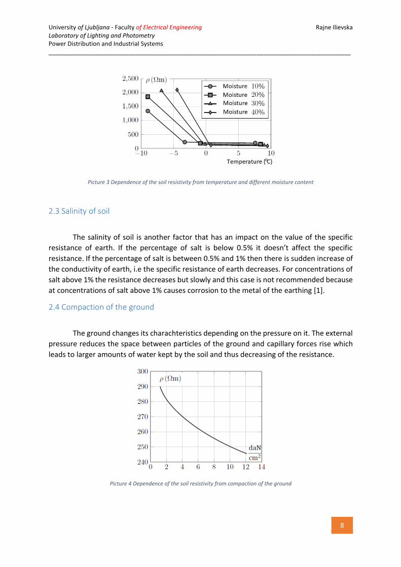
at which the earth doesn’t freeze. Picture 3 shows the dependence between the specific
resistance and the temperature with different percentage of water in the earth.
University of Ljubljana - Faculty of Electrical Engineering Rajne Ilievska Laboratory of Lighting and Photometry Power Distribution and Industrial Systems __________________________________________________________________________________________
8
Picture 3 Dependence of the soil resistivity from temperature and different moisture content
2.3 Salinity of soil
The salinity of soil is another factor that has an impact on the value of the specific
resistance of earth. If the percentage of salt is below 0.5% it doesn’t affect the specific
resistance. If the percentage of salt is between 0.5% and 1% then there is sudden increase of
the conductivity of earth, i.e the specific resistance of earth decreases. For concentrations of
salt above 1% the resistance decreases but slowly and this case is not recommended because
at concentrations of salt above 1% causes corrosion to the metal of the earthing [1].
2.4 Compaction of the ground
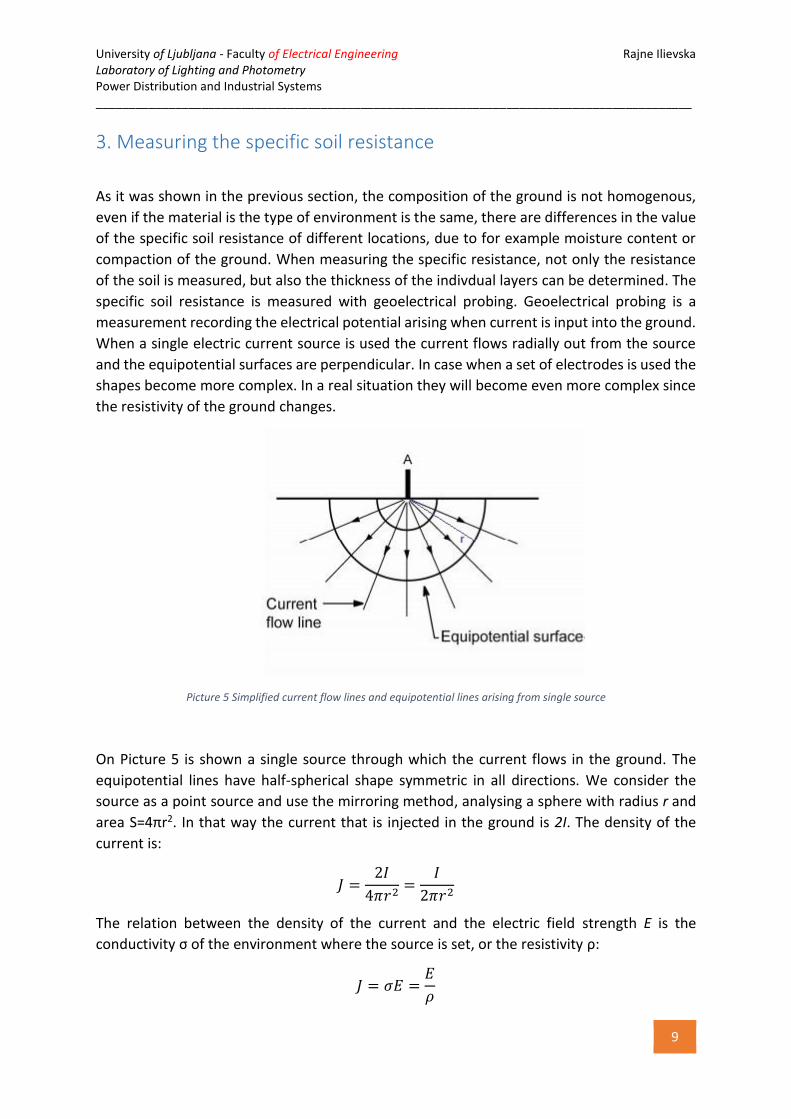
The ground changes its charachteristics depending on the pressure on it. The external
pressure reduces the space between particles of the ground and capillary forces rise which
leads to larger amounts of water kept by the soil and thus decreasing of the resistance.
Picture 4 Dependence of the soil resistivity from compaction of the ground
University of Ljubljana - Faculty of Electrical Engineering Rajne Ilievska Laboratory of Lighting and Photometry Power Distribution and Industrial Systems __________________________________________________________________________________________
9
3. Measuring the specific soil resistance
As it was shown in the previous section, the composition of the ground is not homogenous,
even if the material is the type of environment is the same, there are differences in the value
of the specific soil resistance of different locations, due to for example moisture content or
compaction of the ground. When measuring the specific resistance, not only the resistance
of the soil is measured, but also the thickness of the indivdual layers can be determined. The
specific soil resistance is measured with geoelectrical probing. Geoelectrical probing is a
measurement recording the electrical potential arising when current is input into the ground.
When a single electric current source is used the current flows radially out from the source
and the equipotential surfaces are perpendicular. In case when a set of electrodes is used the
shapes become more complex. In a real situation they will become even more complex since
the resistivity of the ground changes.
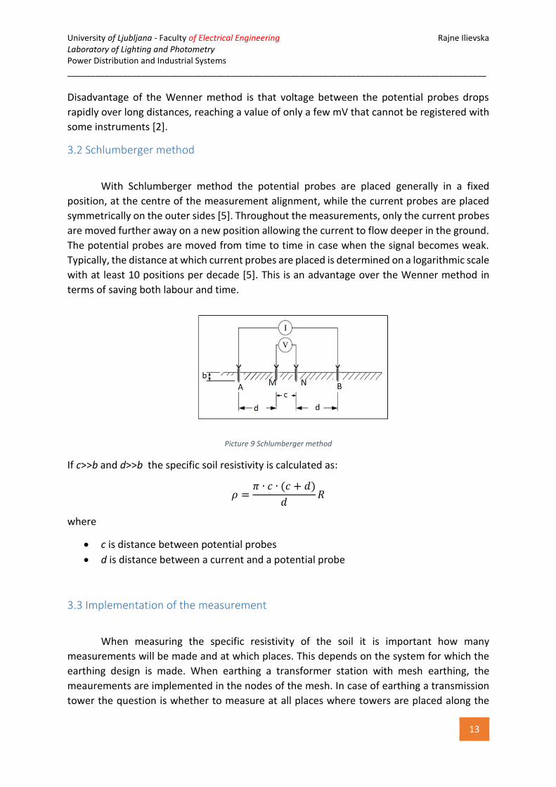
Picture 5 Simplified current flow lines and equipotential lines arising from single source
On Picture 5 is shown a single source through which the current flows in the ground. Тhe
equipotential lines have half-spherical shape symmetric in all directions. We consider the
source as a point source and use the mirroring method, analysing a sphere with radius r and
area S=4πr2. In that way the current that is injected in the ground is 2I. The density of the
current is:
𝐽 =2𝐼
4𝜋𝑟2=
𝐼
2𝜋𝑟2
The relation between the density of the current and the electric field strength E is the
conductivity σ of the environment where the source is set, or the resistivity ρ:
𝐽 = 𝜎𝐸 =𝐸
𝜌

University of Ljubljana - Faculty of Electrical Engineering Rajne Ilievska Laboratory of Lighting and Photometry Power Distribution and Industrial Systems __________________________________________________________________________________________
10
The electric field strength is then:
𝐸 =𝜌 ∙ 𝐼
2𝜋𝑟2
If 𝜑∞ is the potential of the reference earth in infinity and we assume that 𝜑∞ = 0, then the
potential on distance r is:
𝜑𝑟 = 𝜑∞ + ∫ 𝐸(𝑟) ∙ 𝑑𝑟∞
𝑟
= 0 + ∫𝜌𝐼
2𝜋𝑟2𝑑𝑟 =
𝜌𝐼
2𝜋𝑟
∞
𝑟
This equation is later used in calculation of the soil resistivity.
The number of electrodes can be different and electrodes can be placed differently. According
to this there are few possible methods of measuring. Most commonly the methods for
measuring soil resistivity are methods with 3 probes and methods with 4 probes. The most
commonly used methods are the methods with 4 probes such as Wenner method and
Schlumberger method.
Picture 6 Most commonly used configurations of the method with 4 probes. A and B denote current probes, M and N denote potential probes
3.1 Wenner method
The Wenner method (Frank Wenner, USA, 1915) is a method that uses 4 probes: two inner
probes are potential and two outer probes are current probes. They are placed on equal distances a
as it is shown on Picture 7.

University of Ljubljana - Faculty of Electrical Engineering Rajne Ilievska Laboratory of Lighting and Photometry Power Distribution and Industrial Systems __________________________________________________________________________________________
11
Picture 7 Wenner method
The outer probes are connected to a current source and the inner probes are connected to a
voltmeter for measuring the potential difference between the points of the ground where the
probes are placed. The current source and the measuring devices are usually placed in one
single instrument. This instrument shows the current which flows between current probes
and the voltage between potential probes [2].
3.1.1 Calculation of soil resistivity
If the dimensions of the probes are negligible compared to the distance between them, we
can treat them as points. The potentials of the probes M and N are:
𝜑𝑀 =𝐼 ∙ 𝜌
2𝜋𝑎−
𝐼 ∙ 𝜌
2𝜋2𝑎=
𝐼 ∙ 𝜌
4𝜋𝑎
𝜑𝑁 =𝐼 ∙ 𝜌
2𝜋2𝑎−
𝐼 ∙ 𝜌
2𝜋𝑎= −
𝐼 ∙ 𝜌
4𝜋𝑎
where
ρ is soil resistivity
I is the current which flows through the current probes
a is the distance (spacing) between the probes
The voltage between probes M and N is:
𝑈𝑀𝑁 = 𝜑𝑀 − 𝜑𝑁 =𝐼 ∙ 𝜌
2𝜋𝑎
The soil resistance is then:
𝜌 =𝑈𝑀𝑁
𝐼∙ 2𝜋𝑎

University of Ljubljana - Faculty of Electrical Engineering Rajne Ilievska Laboratory of Lighting and Photometry Power Distribution and Industrial Systems __________________________________________________________________________________________
12
𝜌 = 𝑅 ∙ 2𝜋𝑎
where
R is the measured value of the resistance with an instrument
This equation is valid when a≥10·b , where b is depth of digging of the probes. If a<10·b , this
means that the probes are placed close to each other on distances less than 3 m, since the
depth is usually 20 to 30 cm [2].
Picture 8 Wenner method for small distances of the probes
In this case, when calculating the soil resistivity, it should be taken into account the depth of
digging b. Here, the probes are also treated as points and the mirroring method is used. Points
A and B are mirrored in A’ and B’ in terms to the boundary ground-air. The boundary is
eliminated and we consider an area with specific soil resistance ρ.
Therefore, the potential in point M is:
𝜑𝑀 =𝐼 ∙ 𝜌
4𝜋(1
𝑎−
1
2𝑎+
1
√𝑎2 + 4𝑏2−
1
√4𝑎2 + 4𝑏2)
and the potential in point N is:
𝜑𝑁 =𝐼 ∙ 𝜌
4𝜋(
1
2𝑎−
1
𝑎+
1
√4𝑎2 + 4𝑏2−
1
√𝑎2 + 4𝑏2)
After arranging of the equations, the equation for calculating soil resistivity for small
measuring distances is obtained:
𝜌 =4𝜋𝑎 ∙ 𝑅
1 +2𝑎
√𝑎2 + 4𝑏2−
2𝑎
√4𝑎2 + 4𝑏2
The measuring is repeated many times for different values of the distance a (1m, 2m, 3m, 5m,
8m, 10m…). Distances larger than 10 m are used when the results from the previous measures
indicate that the soil has extremely non-homogenous structure, or the purpose of measuring
is not only earthing, but also some other calculations [1].
University of Ljubljana - Faculty of Electrical Engineering Rajne Ilievska Laboratory of Lighting and Photometry Power Distribution and Industrial Systems __________________________________________________________________________________________
13
Disadvantage of the Wenner method is that voltage between the potential probes drops
rapidly over long distances, reaching a value of only a few mV that cannot be registered with
some instruments [2].
3.2 Schlumberger method
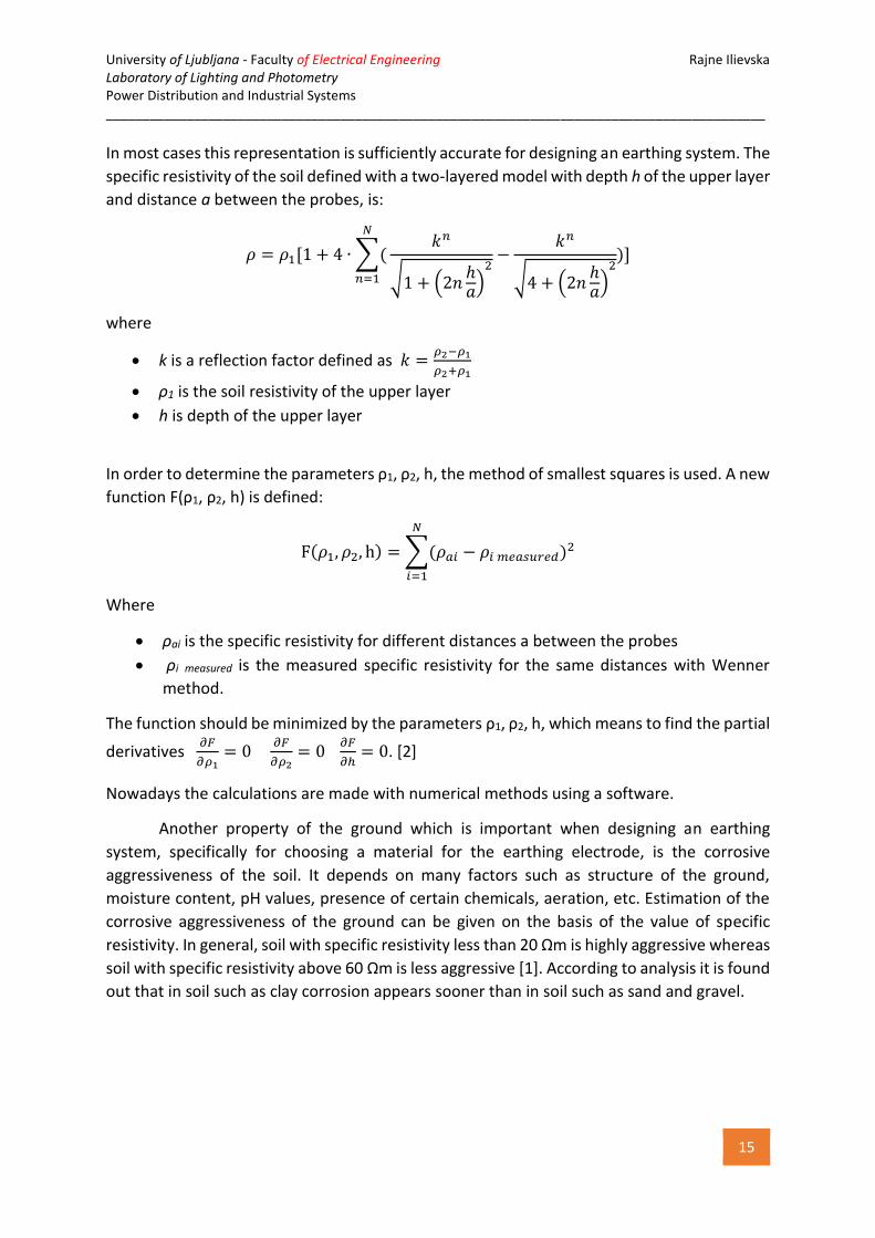
With Schlumberger method the potential probes are placed generally in a fixed
position, at the centre of the measurement alignment, while the current probes are placed
symmetrically on the outer sides [5]. Throughout the measurements, only the current probes
are moved further away on a new position allowing the current to flow deeper in the ground.
The potential probes are moved from time to time in case when the signal becomes weak.
Typically, the distance at which current probes are placed is determined on a logarithmic scale
with at least 10 positions per decade [5]. This is an advantage over the Wenner method in
terms of saving both labour and time.
Picture 9 Schlumberger method
If c>>b and d>>b the specific soil resistivity is calculated as:
𝜌 =𝜋 ∙ 𝑐 ∙ (𝑐 + 𝑑)
𝑑𝑅
where
c is distance between potential probes
d is distance between a current and a potential probe
3.3 Implementation of the measurement
When measuring the specific resistivity of the soil it is important how many
measurements will be made and at which places. This depends on the system for which the
earthing design is made. When earthing a transformer station with mesh earthing, the
meaurements are implemented in the nodes of the mesh. In case of earthing a transmission
tower the question is whether to measure at all places where towers are placed along the

University of Ljubljana - Faculty of Electrical Engineering Rajne Ilievska Laboratory of Lighting and Photometry Power Distribution and Industrial Systems __________________________________________________________________________________________
14
line, or to perform measurements just on a selected number of places. The initial approach is
to perform measurements at two adjacent places. If it is estimated that the resistivity of soil
does not change significantly, then the measurements are performed at specific places, for
example at every third or fifth tower. However, if the environment is extremely changing in
geological structure, measurements have to be performed at each tower place.
4. Interpretation of the results
Probably, the most difficult part of the measurement is the interpretation of the
results. The objective is to find an analytical procedure for the number, the thickness and the
specific resistivity of each layer of the soil. In other words, a soil model has to be defined in
that way that it is approximately a good match of the actual soil, since a perfect match is
unlikely to be derived. Usually the models that are used are the uniform model and the two-
layered model of the ground. Multi-layered models may be used if the conditions are more
complex.
A uniform model is used if there is not a significant variation in the specific resistivity
for various probe spacings. The soil resistivity is calculated as an average value of the
measured data:
𝜌 =𝜌1 + 𝜌2 + ⋯ + 𝜌𝑛
𝑛
However, in most of the cases the soil will not meet the criteria for using this equation.
In general, the soil is never homogenous, most often it has many layers that may be
horizontal, or in some cases vertical. The depth and the specific resistivity of the layers can be
determined with an analytical procedure. It is assumed that the ground is horizontally layered,
usually approximated with a two-layered model. The assumption for a horizontally layered
model is quite ideal, however it is the most acceptable approximation. This model consists of
an upper layer with finite depth h and a lower layer with infinite depth.
Picture 10 Two-layered model of the ground
University of Ljubljana - Faculty of Electrical Engineering Rajne Ilievska Laboratory of Lighting and Photometry Power Distribution and Industrial Systems __________________________________________________________________________________________
15
In most cases this representation is sufficiently accurate for designing an earthing system. The
specific resistivity of the soil defined with a two-layered model with depth h of the upper layer
and distance a between the probes, is:
𝜌 = 𝜌1[1 + 4 ∙ ∑(
𝑁
𝑛=1
𝑘𝑛
√1 + (2𝑛ℎ𝑎)
2−
𝑘𝑛
√4 + (2𝑛ℎ𝑎)
2)]
where
k is a reflection factor defined as 𝑘 =𝜌2−𝜌1
𝜌2+𝜌1
ρ1 is the soil resistivity of the upper layer
h is depth of the upper layer
In order to determine the parameters ρ1, ρ2, h, the method of smallest squares is used. A new
function F(ρ1, ρ2, h) is defined:
F(𝜌1, 𝜌2, h) = ∑(𝜌𝑎𝑖 − 𝜌𝑖 𝑚𝑒𝑎𝑠𝑢𝑟𝑒𝑑)2
𝑁
𝑖=1
Where
ρai is the specific resistivity for different distances a between the probes
ρi measured is the measured specific resistivity for the same distances with Wenner
method.
The function should be minimized by the parameters ρ1, ρ2, h, which means to find the partial
derivatives 𝜕𝐹
𝜕𝜌1= 0
𝜕𝐹
𝜕𝜌2= 0
𝜕𝐹
𝜕ℎ= 0. [2]
Nowadays the calculations are made with numerical methods using a software.
Another property of the ground which is important when designing an earthing
system, specifically for choosing a material for the earthing electrode, is the corrosive
aggressiveness of the soil. It depends on many factors such as structure of the ground,
moisture content, pH values, presence of certain chemicals, aeration, etc. Estimation of the
corrosive aggressiveness of the ground can be given on the basis of the value of specific
resistivity. In general, soil with specific resistivity less than 20 Ωm is highly aggressive whereas
soil with specific resistivity above 60 Ωm is less aggressive [1]. According to analysis it is found
out that in soil such as clay corrosion appears sooner than in soil such as sand and gravel.

University of Ljubljana - Faculty of Electrical Engineering Rajne Ilievska Laboratory of Lighting and Photometry Power Distribution and Industrial Systems __________________________________________________________________________________________
16
5. Types of earthing
According to the purpose of earthing it can be:
- Protective earthing
- Functional earthing
- Earthing for atmospheric discharge
Protective earthing refers to earthing of all the metal parts of a building that do not belong to
an electric circuit, nor are they found directly in electrical contact with them, and yet, in case
of fault they can come under voltage [1]. The protective earth electrode reduces the voltage
and thus prevents the possibility of occurrence on conditions that are dangerous to the lives
of people who operate with the appliances or equipment affected with the defect, or moving
in their vicinity. Functional earthing refers to earthing of a part of an electric circuit that
provides certain function or performance characteristic of that circuit, such as neutral point
of generators and transformers, neutral conductor, etc [1]. It can be direct or indirect
earthing. Direct earthing is performed by directly connecting to the earthing system, whereas
indirect earthing through some impedance. Earthing for atmospheric discharge refers to
earthing of a lightning installation and serves to drain the current of atmospheric discharge in
the ground.
According to the position in the ground earthing electrodes are divided into:
- Horizontal
- Vertical
Horizontal earthing device is composed of horizontally laid elements (electrodes), which are
in the ground at relatively low depth. The shape of the horizontal earthing device can be
mesh, ring, triangle, rectangular or complex as a combination of some of the mentioned
forms. Vertical earthing device consists of one or more vertical rods in the ground that are
galvanically connected. The length of the rod is usually 2m to 5m, although sometimes when
the lower layers of the soil have small specific resistance, the length can be greater [1]. To
eliminate the danger of too high potential of the vertical electrode it is necessary to perform
the so-called '''shaping of the potential''. This is achieved with additional placement of one or
two rings around the rod.
Picture 11 Example of different types of configurations of earthing electrodes

University of Ljubljana - Faculty of Electrical Engineering Rajne Ilievska Laboratory of Lighting and Photometry Power Distribution and Industrial Systems __________________________________________________________________________________________
17
5.1 Materials of the earthing electrodes and application
Materials which are most commonly used for the earthing electrodes are galvanized
iron, copper, iron or steel coated with lead or copper and other materials. Earthing electrodes
made of iron are common in practice but they are affected by corrosion, that depends on the
structure of the soil where the electrodes are set. Copper has significantly better
characteristics than iron, but it is an expensive material. In some cases it is given preference
over other materials.
Depending on the configuration, horizontal and vertical earthing electrodes have
different application. When earthing a transmission tower for overhead line most commonly
used is horizontal configuration. Vertical configuration is not common for earthing system of
transmission towers, except in cases when the soil has many layers and deeper layers have
lower value of the resistivity, or the surrounding of the tower is limited and a horizontal
configuration is not feasible. Vertical configuration is mostly used with a mesh earthing of a
transformer substations. Usually they are in shape of a rod with length 2-5m or a specific
shapes like letters “L”, “U” or “T”. [1]
6. Measurement and calculation of earthing
To determine the resistance of the earthing, the distribution of potentials along the
surface and the frequency histograms of touch voltage and step voltage in order to get their
maximum, minimum and average values, there are few approaches:
- Direct measurements
- Model experiments in laboratory
- Calculations
Nowadays, with the development of technology, computer calculations are mostly applied,
while experimental methods are practically out of use. Using mathematical models and
numerical methods results are obtained with very high accuracy.
6.1 Measurement
Direct measurements of the earthing are based on U-I method, using potential and
current probe and autonomous measuring instrument, known as earthing tester. Current is
injected through the earthing that returns to the current probe through the ground, closing
the electric circuit. The current is rising the potential and by shifting of the potential probe on
equal distances, the potential of the earthing is recorded. According to the Ohm’s law the
tester automatically calculates the resistance of the earth electrode. With such an instrument
it is possible to measure also the soil resistivity.

University of Ljubljana - Faculty of Electrical Engineering Rajne Ilievska Laboratory of Lighting and Photometry Power Distribution and Industrial Systems __________________________________________________________________________________________
18
Picture 12 U-I method for measuring earthing resistance
On Picture 12 is shown the U-I method for measuring the resistance of earthing electrode
Re. The voltage between the earthing electrode and the potential probe is:
𝑈𝐸−𝑃 = 𝜑𝐸 − 𝜑𝑃 = 𝜑𝐸𝐸 − 𝜑𝐸
𝐶 − 𝜑𝑃𝐸 + 𝜑𝑃
𝐶
where
𝜑𝐸𝐸 is the potential of the earthing electrode caused by the current flowing in the
earthing electrode
𝜑𝐸𝐶 is the potential of the earthing electrode caused by the current flowing out of the
current probe
𝜑𝑃𝐸 is the potential of the potential probe caused by the current flowing in the earthing
electrode
𝜑𝑃𝐶 is the potential of the potential probe caused by the current flowing out of the
current probe
The exact value of the resistance of the earthing electrode s measured when:
−𝜑𝐸𝐶 − 𝜑𝑃
𝐸 + 𝜑𝑃𝐶 = 0
−𝜌𝐼
2𝜋𝐿𝑐−
𝜌𝐼
2𝜋𝐿𝑝+
𝜌𝐼
2𝜋(𝐿𝑐 − 𝐿𝑝)= 0
The solution in terms of Lp gives the location of the potential probe which is Lp=0.618·Lc ,
which is known as “61,8%” rule. [2]
University of Ljubljana - Faculty of Electrical Engineering Rajne Ilievska Laboratory of Lighting and Photometry Power Distribution and Industrial Systems __________________________________________________________________________________________
19
Picture 13 Measured earthing resistance
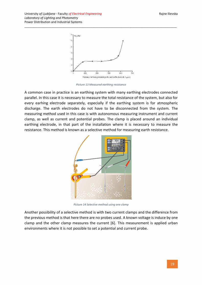
A common case in practice is an earthing system with many earthing electrodes connected
parallel. In this case it is necessary to measure the total resistance of the system, but also for
every earhing electrode separately, especially if the earthing system is for atmospheric
discharge. The earth electrodes do not have to be disconnected from the system. The
measuring method used in this case is with autonomous measuring instrument and current
clamp, as well as current and potential probes. The clamp is placed around an individual
earthing electrode, in that part of the installation where it is necessary to measure the
resistance. This method is known as a selective method for measuring earth resistance.
Picture 14 Selective method using one clamp
Another possibility of a selective method is with two current clamps and the difference from
the previous method is that here there are no probes used. A known voltage is induce by one
clamp and the other clamp measures the current [6]. This measurement is applied urban
environments where it is not possible to set a potential and current probe.

University of Ljubljana - Faculty of Electrical Engineering Rajne Ilievska Laboratory of Lighting and Photometry Power Distribution and Industrial Systems __________________________________________________________________________________________
20
Picture 15 Selective method using two clamps
As a specific case it should be mentioned the measurement of the resistance of transmission
towers for overhead lines. Transmission towers are earthed with individual earthing
electrodes under the tower or in the immediate vicinity. There is a shield wire above the
overhead line that is connected with each transmission tower and has galvanic connection
with the individual earthing electrodes. The role of the shield wire is protection of overhead
lines from direct lightning strike. Since all the earthng electrodes are connected through the
shield wire, the measuring of individual resistances becomes difficult. Disconnection of the
shield wire is not taken into account. There are special autonomous measuring instruments
for transmission towers, which measure the resistance of the individual earthing electrodes
without having to disconnect the shield wire. This instrument has source of alternating
current with high frequency up to 150 Hz. The primary task of the earthing of transmission
towers and overhead lines is protection against direct lightning strike. Therefore, to measure
the performance of the earthing relevant parameter is the so-called impulse resistance Ri of
the earthing electrode. The impulse resistance should be also measured with the high
frequency measuring instrument.
Picture 16 Earthing of transmission towers for overhead lines

University of Ljubljana - Faculty of Electrical Engineering Rajne Ilievska Laboratory of Lighting and Photometry Power Distribution and Industrial Systems __________________________________________________________________________________________
21
6.2 Calculation
When calculating the parameters of the earthing, some empirical formulas are often
used. Depending on the configuration of the earthing there are different equations for
calculating the resistance of earthing.
If the earthing electrode is vertical rod, set in soil with resistvity ρ, then the earth resistance
of propagation is calculated as:
𝑅𝑒 =𝜌
2𝜋𝑙∙ 𝑙𝑛
4𝑙
𝑑
where
l is the length of the rod
d is the diameter of the rod
If the earthing electrode is set horizontally in the ground, the earth resistance of propagation
is calculated as:
𝑅𝑒 =𝜌
𝜋𝑙∙ 𝑙𝑛
𝑙
√ℎ ∙ 𝑑
where
l is the length of the electrode
d is the diameter of the electrode
h is the depth at which the electrode is set
The earthing can be also half-spherical. In this case the earth resistance of propagation is
calculated with the following equation:
𝑅 =𝜌
𝜋 ∙ 𝐷
where
D is the diameter of the sphere
Picture 17 Half-spherical earthing

University of Ljubljana - Faculty of Electrical Engineering Rajne Ilievska Laboratory of Lighting and Photometry Power Distribution and Industrial Systems __________________________________________________________________________________________
22
These empirical relations are simple, yet sufficiently accurate for simple and quick calculations
of the performance of the earthing system. However, in practice the earthing system is often
more complex in terms of configuration and shape of the earthing electrodes. It can be in a
shape of a ring, triangle, rectangular, star connection of the electrodes etc. All the elements
that the earthng system contains, also the different configuration of the system, affect the
parameters of earthing. For achieving results with greater accuracy it is necessary to use some
numerical method. With a numerical method we assume that the earthing consists of n linear
conductors that are galvanic connected, set in a homogenous soil with known resistivity.
According to this, with using the method of superposition, a system of Maxwell equations is
set, that describes the relation between individual elements of the system. Calculation is
reduced to solving a system of linear equations. By solving them, the parameters of the
earthing are determined. This is also applied for situations when two or more earthing
systems that do not have a galvanic bond are located close enough and affect one to another.
This refers to conductively coupled earthng.
7. Impulse resistance
As it was mentioned previously, under high impulse currents, like the current from
lightning strike, the resistance of the earthing electrode changes. Not only the resistance of
the electrode is changed, but also the resistance of the soil changes.
The impulse resistance of the earthing electrode is defined as:
𝑅𝑖 = 𝛼 ∙ 𝑅𝑒
where
α is factor of impulsiveness
Factor α has higher values for long horizontal earthing electrodes [1].
When lightning strikes, the impulse current that passes through the electrode creates
magnetic flux around the electrode. At the beginning when the change of the current is large,
the inductivity of the earthing electrode prevents the current flowing through the total length
of the earthing electrode. As a result, the current finds ways of flowing through the ground
at the beginnng, not passing the total length. Therefore, the resistance of the earthing
electrode is increased, i.e. the impulse resistance of the earthing electrode is higher than the
resistance in case of low frequency current.

University of Ljubljana - Faculty of Electrical Engineering Rajne Ilievska Laboratory of Lighting and Photometry Power Distribution and Industrial Systems __________________________________________________________________________________________
23
Picture 18 Variation of earthing resistance of the electrode under impulse discharge
The previous equation can be used for calculating the impulse resistance if the factor α is
known and the standard value of resistance in case of low frequency current. Factor of
impulse is different for different types of earthing electrodes and various empirical equations
exist. Another way of calculating the impulse resistance is with calculation of the active length
of the electrode:
𝑙𝑎 = √𝑇𝑐
𝐿1 ∙ 𝐺1
where
L1 is longitudinal inductance
G1 is longitudinal conductivity
Tc is time constant of change of impulse current
𝐿1 =𝜇0
2𝜋𝑙𝑛
2𝑙
𝑑
𝐺1 =1
𝑅𝑒 ∙ 𝑙
Depending on the time constant, impulse resistance can be calculated as:
𝑅𝑖 =1
𝐺1∙𝑙 if Tc > 1.49·G1·l2
𝑅𝑖 =1.21
√𝐺1∙𝑇𝑐 if Tc ≤ 1.49·G1·l2
where
l is the length of the electrode
In the first case the active length is approximately equal to the total length of the earthing
electrode, which means that the earthing electrode has total share in conducting the current,

University of Ljubljana - Faculty of Electrical Engineering Rajne Ilievska Laboratory of Lighting and Photometry Power Distribution and Industrial Systems __________________________________________________________________________________________
24
i.e. Ri=Re. In the second case the impulse resistance is larger, which means that in the period
of the impulse the earthng electrode is conducting only with the active length.
On the other hand, under high impulse currents the earth resistance of the soil is
reduced. The high impulsive current establishes a strong electric field in the ground that
causes ionisation of the soil. The reduction of the resistance of the soil is a result of the
ionisation.

University of Ljubljana - Faculty of Electrical Engineering Rajne Ilievska Laboratory of Lighting and Photometry Power Distribution and Industrial Systems __________________________________________________________________________________________
25
8. Conclusion
This seminar paper shows the basic measurements and calculations that have to be
done when designing an earthing system. Methods for measuring the specific soil resistance
and the resistance of the earthing electrodes were reviewed. One of the most commonly used
methods for measuring the soil resistivity is the Wenner method. Simple formulas were
presented for determination of the resistance. However, for more accurate calculations
nowadays are used numerical methods and computer calculations.
9. Questions
1. What is soil resistance and from which factors depends its value?
Soil resistance is an electric property of earth’s soil that shows how much the soil resists the
flow of electricity. The earth’s soil resistance varies in wide range of values depending on the
composition of the ground. Factors which have an impact on the value of the soil resistance
are: moisture content in the soil, the temperature, the amount of salts dissolved in the water,
the compaction of the ground.
2. Which methods are used for measuring the specific soil resistivity?
The specific soil resistance is measured with geoelectrical probing which is a measurement
recording the electrical potential arising when current is injected into the ground. According
to the number of probes and their placement there are few possible methods of measuring:
method with 2 probes, method with 3 probes, method with 4 probes. Wenner method and
Schlumberger method which are commonly used, are methods with 4 probes, the difference
is in the placement of the probes.
3. Which types of earthing electrodes are used in earthing systems?
Earthing electrodes which are used in earthing systems can be horizontal and vertical.
Horizontal earthing electrodes are laid horizontally in the ground at relatively low depth. The
shape of the horizontal earthing device can be mesh, ring or complex such as half-sphere or
combination of some of the mentioned forms. Vertical earthing electrode is a rod placed in
the ground usually on depth 2 m to 5 m, or sometimes deeper. It can be in shape of letters
''L'', ''U'', ''T'' or similar.
4. How is measured the earthing resistance?
Direct measurements of the earthing are based on U-I method, using potential and current
probe and autonomous measuring instrument, known as earthing tester. The current injected
through the earthing electrode and the current probe, is rising the potential and by shifting
the potential probe on equal distances, the potential of the earthing is recorded. The tester

University of Ljubljana - Faculty of Electrical Engineering Rajne Ilievska Laboratory of Lighting and Photometry Power Distribution and Industrial Systems __________________________________________________________________________________________
26
automatically calculates the resistance of the earth electrode. In case when the system has
many earthing electrodes for measuring the resistance of the individual electrodes, clamps
are used.
5. How does a high impulsive current affects on the resistance of the earthing electrode and
on the soil resistance?
High impulsive current increases the resistance of the earthing electrode, while the resistance
of the soil is reduced due to ionisation.
10. Calculation example
The specific resistance of the soil is measured with the Wenner method. For distances of the
probes a1=1 m, a2=3 m, a3=5 m and a4=7 m the measured resistances are R1=39 Ω, R2=41 Ω,
R3=78.3 Ω R4=69 Ω respectively. If the probes were set on depth 0.3 m calculate the specific
resistance of the soil for each measurement. What can we conclude for the structure of the
soil based on the results?
a1=1 m R1=39 Ω ρ1=?
a2=3 m R2=41 Ω ρ2=?
a3=5 m R3=78.3 Ω ρ3=?
a4=7 m R4=69 Ω ρ4=?
b=0.3 m
Solution:
In the first measurement the distance between the probes is less than 3 m, i.e a<10·b, the
specific resistance of the soil is calculated as:
𝜌1 =4𝜋𝑎1 ∙ 𝑅1
1 +2𝑎1
√𝑎12 + 4𝑏2
−2𝑎1
√4𝑎12 + 4𝑏2
=4𝜋 ∙ 1 ∙ 39
1 +2 ∙ 1
√12 + 4 ∙ 0.32−
2 ∙ 1
√4 ∙ 12 + 4 ∙ 0.32
= 278.9 Ω𝑚
In all the other measurements the distance between the probes is a≥10·b. The soil resistivity
is then calculated as:
𝜌2 = 𝑅2 ∙ 2𝜋𝑎2 = 41 ∙ 2𝜋 ∙ 3 = 772.8 Ω𝑚
𝜌3 = 𝑅3 ∙ 2𝜋𝑎3 = 78.3 ∙ 2𝜋 ∙ 5 = 2459.9 Ω𝑚
𝜌4 = 𝑅4 ∙ 2𝜋𝑎4 = 69 ∙ 2𝜋 ∙ 7 = 3034.8 Ω𝑚
The results show that the resistance of the soil varies greatly, so we can say that the structure
of the soil is not homogenous.

University of Ljubljana - Faculty of Electrical Engineering Rajne Ilievska Laboratory of Lighting and Photometry Power Distribution and Industrial Systems __________________________________________________________________________________________
27
References
[1] R. Achkovski, Zazemjuvanje i zazemjuvachki sistemi vo elektroenergetskite mrezi, Skopje, 2008.
[2] V. Dimchev, Merenje vo elektroenergetikata, Skopje, 2014.
[3] H. Požar, Visokonaponska rasklopna postrojenja, Zagreb, 1973.
[4] C.Bayliss, B.Hardy, Transmission and Distribution Electrical Engineering.
[5] Moller, Sorensen & Auken, Geoelectrical methods.
[6] “Earth ground testers,” FLUKE, [Online]. Available: www.fluke.com.