EARTH PROJECT - CORDIS · EARTH PROJECT EARTH_WP6_D6.2b 4 / 53 Authors Partner Name Email...
53
EARTH PROJECT EARTH_WP6_D6.2b 1 / 53 INFSO-ICT-247733 EARTH Deliverable D6.2b Draft Integrated Solutions Abstract: The overall target of the EARTH project is to reduce the power consumption of mobile broadband networks by 50% with preserved quality of service. This report is the second in a series of three, which will report the progress of the work on integrating the different “Green Network” and “Green Radio” solutions into an overall energy efficient EARTH solution, including verification of that the 50% target is met. The document outlines the methodology for how this will be carried out, presents the outcome of the first filtering of the technology tracks, and summarizes the work on defining draft integrated solutions. Keyword list: Mobile communications, energy efficiency, green networks, green radios, integrated solution, holistic evaluation. Contractual Date of Delivery: December 31, 2011 Actual Date of Delivery: January 30, 2012 Editor: Magnus Olsson (EAB) Author(s): Muhammad Ali Imran (UNIS), Oliver Blume (ALUD), Mauro Boldi (TI) Per Burström (EAB), Emilio Calvanesi Strinati (CEA), Luís M. Correia (IST), Péter Fazekas (BME), Albrecht Fehske (TUD), Dieter Ferling (ALUD), Yolanda Fernández (TTI), István Gódor (ETH), Rohit Gupta (CEA), László Hévizi (ETH), Ylva Jading (EAB), Efstathios Katranaras (UNIS), Magnus Olsson (EAB), Sven Petersson (EAB), Yinan Qi (UNIS), Dario Sabella (TI), António Serrador (IST), Per Skillermark (EAB), Attila Vidács (BME), Wieslawa Wajda (ALUD) Participant(s): ALUD, BME, CEA, EAB, ETH, IST, TI, TTI, TUD, UNIS Work package: WP6 Security: Public Version: 1.0
Transcript of EARTH PROJECT - CORDIS · EARTH PROJECT EARTH_WP6_D6.2b 4 / 53 Authors Partner Name Email...
EARTH PROJECT
EARTH_WP6_D6.2b 1 / 53
INFSO-ICT-247733 EARTH
Deliverable D6.2b
Draft Integrated Solutions
Abstract: The overall target of the EARTH project is to reduce the power consumption of mobile broadband networks by 50% with preserved quality of service. This report is the second in a series of three, which will report the progress of the work on integrating the different “Green Network” and “Green Radio” solutions into an overall energy efficient EARTH solution, including verification of that the 50% target is met. The document outlines the methodology for how this will be carried out, presents the outcome of the first filtering of the technology tracks, and summarizes the work on defining draft integrated solutions.
Keyword list: Mobile communications, energy efficiency, green networks, green radios, integrated solution, holistic evaluation.
Contractual Date of Delivery: December 31, 2011
Actual Date of Delivery: January 30, 2012
Editor: Magnus Olsson (EAB)
Author(s): Muhammad Ali Imran (UNIS), Oliver Blume (ALUD), Mauro Boldi (TI) Per Burström (EAB), Emilio Calvanesi Strinati (CEA), Luís M. Correia (IST), Péter Fazekas (BME), Albrecht Fehske (TUD), Dieter Ferling (ALUD), Yolanda Fernández (TTI), István Gódor (ETH), Rohit Gupta (CEA), László Hévizi (ETH), Ylva Jading (EAB), Efstathios Katranaras (UNIS), Magnus Olsson (EAB), Sven Petersson (EAB), Yinan Qi (UNIS), Dario Sabella (TI), António Serrador (IST), Per Skillermark (EAB), Attila Vidács (BME), Wieslawa Wajda (ALUD)
Participant(s): ALUD, BME, CEA, EAB, ETH, IST, TI, TTI, TUD, UNIS
Work package: WP6
Security: Public
Version: 1.0

EARTH PROJECT
EARTH_WP6_D6.2b 2 / 53
Disclaimer: This document reflects the contribution of the participants of the research project EARTH. The European Union and its agencies are not liable or otherwise responsible for the contents of this document; its content reflects the view of its authors only. This document is provided without any warranty and does not constitute any commitment by any participant as to its content, and specifically excludes any warranty of correctness or fitness for a particular purpose. The user will use this document at the user's sole risk.
EARTH PROJECT
EARTH_WP6_D6.2b 3 / 53
Executive Summary
The Energy Aware Radio and neTwork tecHnologies (EARTH) project has an ambitious overall goal to derive solutions that together can decrease the radio access network energy consumption by 50 % with preserved quality of service. These solutions act all the way from more efficient components in the base station, over improvements affecting individual radio links, up to solutions acting on the radio network level such as deployment strategies. Furthermore, the project will not only develop and propose energy efficient solutions in all these areas, but also combine them into an overall EARTH energy efficient integrated solution. In addition, EARTH is committed to have a real impact on networks in operation; hence the target is not only to carry out theoretical studies in this aspect, but also to provide trustworthy proof-of-concepts of the individual solutions and in particular of the overall EARTH energy efficient integrated solution.
This report is the second in a series of three, that will present the work on establishing the EARTH integrated solutions, and also the proof-of-concept work that in the end will verify whether the project met the target of 50% energy savings or not. The document outlines how the proof-of-concept work in EARTH is supposed to work, and in particular how the work on integrated solutions is intended to be carried out. It also describes the process and the criteria that were used in the project for selecting the most promising tracks that will be considered for the integrated solutions, and also the selected tracks are briefly described. Finally, the work on defining draft integrated solutions is reported.
The EARTH proof-of-concept work will be carried out in two ways. The overall holistic evaluation of the EARTH energy efficient integrated solution will be carried out by means of radio network system level simulations according to the evaluation framework developed in the project. However, for certain EARTH building blocks it is seen necessary not to only rely on simulations, but to confirm the theoretical results by validation test in a realistic test environment. Those building blocks are represented by components or base stations, whose behaviour has to be validated. For this purpose, a mobile operator test plant designed to validate in tests node and component behavior of mobile network infrastructure will be utilized as complement to the radio network simulations.
The work on integrated solutions consists of three stages:
1) A conceptual stage, where the different building blocks are combined into suitable configurations tailored to application scenarios.
2) Evaluation, where the configurations are evaluated in these scenarios, and finally combined according to the evaluation framework in order to see the global impact of the EARTH integrated concept.
3) Visualization, where the results from the evaluations are presented in a pedagogic way.
The definition of the first integrated solutions has commenced by sorting the energy efficiency enablers studied in the project according to their time scale of operation, and mapping them to the most suitable application scenario. Then strategies for all energy efficiency enablers have been formulated, and from these a number of suitable configurations have been defined. Some work has also been spent on identifying suitable measures that the adaptation between configurations for the different application scenarios can be based upon.
The next steps in this work are now to further identify and refine the suitable configurations, and then to implement them in the system simulators and start the evaluations. This will be the focus of the work on integrated solutions during the remainder of EARTH, and will be reported in the final deliverable.

EARTH PROJECT
EARTH_WP6_D6.2b 4 / 53
Authors
Partner Name Email
Alcatel-Lucent Deutschland AG (ALUD) Oliver Blume [email protected]
Dieter Ferling [email protected]
Wieslawa Wajda [email protected]
Budapest University of Technology and Economics (BME)
Péter Fazekas [email protected]
Attila Vidács [email protected]
Ericsson AB (EAB) Per Burström [email protected]
Ylva Jading [email protected]
Magnus Olsson [email protected]
Sven Petersson [email protected]
Per Skillermark [email protected]
Ericsson Hungary Ltd (ETH) István Gódor [email protected]
László Hévizi [email protected]
Technische Universität Dresden (TUD) Albrecht Fehske [email protected]
University of Surrey (UNIS) Muhammad Ali Imran [email protected]
Efstathios Katranaras [email protected]
Yinan Qi [email protected]
Telecom Italia S.p.A. (TI) Mauro Boldi [email protected]
Dario Sabella [email protected]
Instituto Superior Técnico (IST-TUL) António Serrador [email protected]
Luís M. Correia [email protected]
TTI Norte, SL (TTI) Yolanda Fernández [email protected]

EARTH PROJECT
EARTH_WP6_D6.2b 5 / 53
Partner Name Email
Commissariat à l'Energie Atomique (CEA) Rohit Gupta [email protected]
Emilio Calvanese Strinati

EARTH PROJECT
EARTH_WP6_D6.2b 6 / 53
Table of Contents
1. INTRODUCTION ................................................................................................................... 11
1.1. BACKGROUND ...................................................................................................................... 11 1.2. INTEGRATED SOLUTIONS ......................................................................................................... 11 1.3. OUTLINE .............................................................................................................................. 12
2. EARTH PROOF-OF-CONCEPTS ............................................................................................... 13
2.1. OVERALL PROOF-OF-CONCEPT METHODOLOGY ............................................................................ 13 2.2. INTEGRATED SOLUTIONS METHODOLOGY .................................................................................... 14
2.2.1. Conceptualization ..................................................................................................................... 14
2.2.1.1. Time scales of operation ............................................................................................................ 15 2.2.1.2. Application scenarios ................................................................................................................. 16
2.2.2. Evaluation ................................................................................................................................. 18 2.2.3. Vizualisation ............................................................................................................................. 19
3. MOST PROMISING TRACKS .................................................................................................. 20
3.1. PROCESS AND CRITERIA ........................................................................................................... 20 3.2. GREEN NETWORKS................................................................................................................. 21
3.2.1. Optimal mix of cell sizes ............................................................................................................ 22 3.2.2. Relays ....................................................................................................................................... 22 3.2.3. Multi-RAT deployment .............................................................................................................. 23 3.2.4. Base station cooperation .......................................................................................................... 24 3.2.5. Adaptive network reconfiguration ............................................................................................ 24 3.2.6. Radio resource management .................................................................................................... 25 3.2.7. Future architectures .................................................................................................................. 26
3.3. GREEN RADIOS ..................................................................................................................... 27
3.3.1. Transceivers for macro-cell base stations .................................................................................. 27 3.3.2. Transceivers for small-cell base stations ................................................................................... 28 3.3.3. Low loss antennas ..................................................................................................................... 29 3.3.4. Beamforming and active antennas ............................................................................................ 29 3.3.5. MIMO transmission .................................................................................................................. 29 3.3.6. Bandwidth adaptation .............................................................................................................. 30 3.3.7. Cell DTX .................................................................................................................................... 30 3.3.8. Adaptability to system dynamics .............................................................................................. 30 3.3.9. Retransmission schemes ........................................................................................................... 31
4. CONCEPTUALIZATION AND IDENTIFICATION OF DRAFT INTEGRATED SOLUTIONS ................. 32
4.1. OVERALL DESIGN CONSIDERATIONS ........................................................................................... 32 4.2. ENERGY EFFICIENCY ENABLERS FOR DIFFERENT NODE TYPES AND DEPLOYMENT AREAS .......................... 32 4.3. COMMON MANAGEMENT OF ENERGY EFFICIENCY ENABLERS ........................................................... 35 4.4. CLASSIFICATION OF EARTH ENERGY EFFICIENCY ENABLERS .............................................................. 36 4.5. DEFINITION OF STRATEGIES ...................................................................................................... 37
4.5.1. Deployment and hardware ....................................................................................................... 37 4.5.2. Network management .............................................................................................................. 41 4.5.3. Radio resource allocation .......................................................................................................... 46
4.6. IDENTIFICATION OF PROMISING CONFIGURATIONS ......................................................................... 47

EARTH PROJECT
EARTH_WP6_D6.2b 7 / 53
4.6.1. Configuration 1 ......................................................................................................................... 48 4.6.2. Configuration 2 ......................................................................................................................... 49 4.6.3. Configuration 3 ......................................................................................................................... 50
5. CONCLUSIONS AND FURTHER WORK ................................................................................... 52
6. REFERENCES ........................................................................................................................ 53
EARTH PROJECT
EARTH_WP6_D6.2b 8 / 53
List of Figures
FIGURE 1. TIME SCALES OF NETWORK OPTIMIZATION. ....................................................................................................................... 15 FIGURE 2. TRADE-OFF BETWEEN EFFECTIVITY AND FLEXIBILITY OF NETWORK OPTIMIZATION STRATEGIES...................................................... 15 FIGURE 3. NETWORK CONFIGURATION AS A SELECTION OF STRATEGIES ON EACH TIME SCALE. ................................................................... 16 FIGURE 4. MATRIX ILLUSTRATING APPLICATION SCENARIOS. ............................................................................................................... 17 FIGURE 5. INTEGRATED SOLUTIONS SELECTION PROCEDURE................................................................................................................ 17 FIGURE 6. E
3F MECHANISM FOR GLOBAL SCALE AGGREGATION. .......................................................................................................... 18
FIGURE 7. EXAMPLE ON ASSIGNING SIMILAR NETWORK CONFIGURATIONS TO AN SLS. ............................................................................. 19 FIGURE 8. CLASSIFYING SITES BASED ON THE APPLICABLE ENERGY EFFICIENCY ENABLERS........................................................................... 34 FIGURE 9. POSITIONING OF THE EE ENABLERS ACCORDING TO DEPLOYMENT SCENARIO (Y-AXIS), OPTIMIZATION TIME SCALE (X-AXIS), AND TRAFFIC
LOAD (COLOUR). ................................................................................................................................................................ 37 FIGURE 10. ENERGY SAVING RESULTS FOR CONFIGURATION 3 AGGREGATED OVER THE DAY ACCORDING TO LONG TERM TRAFFIC MODEL........... 51
List of Tables
TABLE 1. TERMINOLOGY USED IN THE WORK ON INTEGRATED SOLUTIONS. ............................................................................................. 11 TABLE 2. SUMMARY OF CONFIGURATION 1. .................................................................................................................................... 49 TABLE 3. SUMMARY OF CONFIGURATION 2. .................................................................................................................................... 50 TABLE 4. SUMMARY OF CONFIGURATION 3. .................................................................................................................................... 51

EARTH PROJECT
EARTH_WP6_D6.2b 9 / 53
Acronyms and Abbreviations
3GPP 3rd Generation Partnership Project AAS Active Antenna System AF Amplify-and-Forward ASIP Application Specific Instruction Processor BCH Broadcast Channel BF Beamforming BS Base Station BW Bandwidth CA Carrier Aggregation CAP Capacity adaptation CF Compress-and-Forward CoMP Coordinated Multi-Point CQI Channel Quality Indicator CRS Cell specific Reference Symbol CS Circuit Switched CSI Channel State Information DAS Distributed Antenna System DeNB Donor eNB DF Decode-and-Forward DL Downlink DMIMO Distributed MIMO DMRS Demodulation Reference Symbol DSPC Digital Signal Processing and Control DTX Discontinuous Transmission E³F Energy Efficiency Evaluation Framework EARTH Energy Aware Radio and neTwork tecHnologies EDF Earliest Deadline First EE Energy Efficiency eNB Enhanced Node B ETU Enhanced Typical Urban FACH Forward Access Channel FFR Fractional Frequency Reuse FPGA Field Programmable Gate Array GSM Global System for Mobile communications GUI Graphical User Interface HARQ Hybrid Automatic Repeat request HDTV High Definition Television HetNet Heterogeneous Networks HSPA High Speed Packet Access ICIC InterCell Interference Coordination IP Internet Protocol ISD Inter Site Distance ITU International Telecommunication Union LOS Line Of Sight LTE Long Term Evolution

EARTH PROJECT
EARTH_WP6_D6.2b 10 / 53
MBSFN Multicast Broadcast Single Frequency Network MCI Maximum Carrier-to-Interference ratio MCS Modulation and Coding Scheme MIMO Multiple Input Multiple Output MU-MIMO Multi-User MIMO NC Network Coding OPEX Operational Expenditures PA Power Amplifier PAPR Peak-to-Average Power Ratio PF Proportional Fair PMI Precoding Matrix Indicator PRB Physical Resource Block PS Packet Switched QAM Quadrature Amplitude Modulation QoS Quality-of-Service RACH Random Access Channel RAN Radio Access Network RAT Radio Access Technology RF Radio Frequency RF-MIMO Radio Frequency MIMO RI Rank Indicator RNTP Reduced Narrow band Transmit Power RRH Remote Radio Head RRM Radio Resource Management RX Receive(r) SiNAD Signal-to-Noise And Distortion ratio SINR Signal-to-Interference-plus-Noise Ratio SISO Single Input Single Output SLS System Level Simulator SNR Signal-to-Noise Ratio SOTA State Of The Art SU-MIMO Single-User MIMO TMA Tower Mounted Amplifier TRX Transceiver TX Transmit(ter) UE User Equipment UL Uplink WCDMA Wideband Code Division Multiple Access WINNER Wireless World Initiative New Radio
EARTH PROJECT
EARTH_WP6_D6.2b 11 / 53
1. INTRODUCTION
1.1. BACKGROUND
Mobile broadband data traffic is growing rapidly. Worldwide, there are today more than 5 billion subscribers [1], more than half the entire population of the planet. Furthermore, forecasts predict that global traffic volumes may more than double each year up until 2014 [2]. At the same time the demand for higher data rates is increasing. To manage the growing data volumes and to meet the demands for higher data rates mobile broadband networks have been enhanced with, e.g., support for wider bandwidths and multi-antenna transmission and reception. Moreover, a densified network deployment is another means that has been used to meet the increasing demands. Obviously, this growth is accompanied by an increased energy consumption of mobile networks. As a consequence the energy efficiency of mobile communication networks has recently gained increased interest, see e.g. [3][4][5][6].
The Energy Aware Radio and neTwork tecHnologies (EARTH) project [4][7] is a concerted effort with partners from industry and academia that addresses the challenge of improving the energy efficiency of mobile communication networks. It started in 2010 and has the overall goal to derive solutions that together can decrease the radio access network energy consumption by 50 % without degrading quality of service.
1.2. INTEGRATED SOLUTIONS
During the first year of the project, an extensive energy efficiency evaluation framework (E³F ) [8] has been developed, including the reference system and scenarios [9] which constitute the starting point for the project. Furthermore, a large number of energy efficiency solutions, so-called tracks, in the areas of Green Networks and Green Radios have been developed, studied, and initially evaluated [10][11]. Of these tracks, a number have been selected as most promising and these will now be further studied and combined into integrated solutions and in the end constitute the EARTH system, that together with the reference system was introduced in [9].
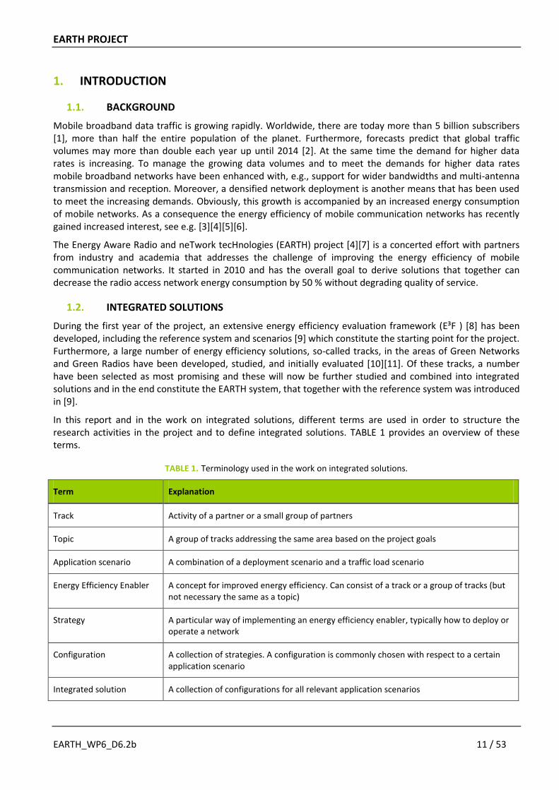
In this report and in the work on integrated solutions, different terms are used in order to structure the research activities in the project and to define integrated solutions. TABLE 1 provides an overview of these terms.
TABLE 1. Terminology used in the work on integrated solutions.
Term Explanation
Track Activity of a partner or a small group of partners
Topic A group of tracks addressing the same area based on the project goals
Application scenario A combination of a deployment scenario and a traffic load scenario
Energy Efficiency Enabler A concept for improved energy efficiency. Can consist of a track or a group of tracks (but not necessary the same as a topic)
Strategy A particular way of implementing an energy efficiency enabler, typically how to deploy or operate a network
Configuration A collection of strategies. A configuration is commonly chosen with respect to a certain application scenario
Integrated solution A collection of configurations for all relevant application scenarios
EARTH PROJECT
EARTH_WP6_D6.2b 12 / 53
This report is the second in a series of three, that will present the work on establishing the EARTH integrated solutions, and also the proof-of-concept work that in the end will verify whether the project met the target of 50% energy savings or not. The first report [12] presented how the work on integrated solutions will be carried out, and also reported initial progress on the definition of the first draft integrated solutions. This report is an update of that report, where in particular the work on defining draft integrated solutions has been further progressed. The third report [13] will report the final outcome of this work, and is due when the EARTH project closes in June 2012.
1.3. OUTLINE
The outline of this report is as follows: In Chapter 2 the proof-of-concept work in EARTH will be described in more detail, and in particular how the work on integrated solutions is intended to be carried out. Then in Chapter 3 the process and the criteria that were used for selecting the most promising tracks will be outlined, and also the selected tracks that will constitute the building blocks for the EARTH integrated solutions will be presented. After that, the work on defining draft integrated solutions will be reported in Chapter 4. Finally, Chapter 5 will conclude the report and give an outlook on the future work that is needed and planned in this activity of the project.
The major updates and modifications compared to the previous report [12] are in chapter 4 where the work on defining draft integrated solutions has been further progressed.
EARTH PROJECT
EARTH_WP6_D6.2b 13 / 53
2. EARTH PROOF-OF-CONCEPTS
EARTH is an ambitious project that targets energy efficiency improvements all the way from more efficient components in the base station, over improvements affecting individual radio links, up to solutions acting on the radio network level such as deployment strategies. Furthermore, the project will not only develop and propose energy efficient solutions in all these areas, but also combine them into an overall EARTH energy efficient integrated solution. In addition, EARTH is committed to have a real impact on networks in operation; hence the target is not only to carry out theoretical studies in this aspect, but also to provide trustworthy proof-of-concepts of the individual solutions and in particular of the overall EARTH energy efficient integrated solution.
2.1. OVERALL PROOF-OF-CONCEPT METHODOLOGY
The EARTH proof-of-concept work will be carried out in two ways. The overall holistic evaluation of the EARTH energy efficient integrated solution will be carried out by means of radio network system level simulations according to the EARTH energy efficiency evaluation framework (E³F) [8]. This framework builds on the widely accepted state-of-the-art to evaluate the performance of a wireless network by simulating the relevant aspects of the radio access network (RAN) at system level. This methodology is an outcome of extensive consensus work from standardization bodies, such as 3GPP [14], and international research projects, such as the EU project Wireless World Initiative New Radio (WINNER) [15], with partners from academia as well as from industry. In order to capture energy efficiency aspects, EARTH has enhanced the methodology with the necessary amendments such as power models, large scale deployment models, long term traffic models, and energy efficiency metrics. The end result is an energy efficiency evaluation framework (E³F) that is able to provide an overall holistic energy efficiency evaluation of radio access networks all the way from individual components in the base station up to network level on country scale.
However, for certain EARTH building blocks it is seen necessary not to only rely on simulations and analytical methods, but to confirm the theoretical results by validation test in a realistic test environment. Those building blocks are represented by components or base stations, whose behaviour has to be validated. For this purpose, a mobile operator test plant designed to validate in tests node and component behavior of mobile network infrastructure will be utilized. Note, however, that it is not meant in this test plant to provide for over-the-air tests of the radio as done in field tests, but rather to validate node and component behavior for which validation by simulations is not considered as sufficient.
All in all, these two activities will complement each other and constitute a powerful proof-of-concept of the EARTH integrated solutions. For the validation of EARTH solutions on a system level including the air-interface, system simulations are considered as the most appropriate way for validation. The validity of the simulation results rest on the validity of the air-interface and the component/node modeling used in these simulations. Validity of the air-interface modeling is ensured by the application of commonly adopted models as e.g. used in standards [14], while validity of the component/node models is inter alia provided by validation tests in the test plant.
The activities related to the test plant are out of the scope of this report, and are reported in [16][17][18]. Instead, this report, its predecessor [12], and its successor [13] focus on the overall holistic evaluation of the EARTH integrated solutions, which consists of a number of stages. These stages are further described in the next section.
EARTH PROJECT
EARTH_WP6_D6.2b 14 / 53
2.2. INTEGRATED SOLUTIONS METHODOLOGY
The target for the work on integrated solutions is to consolidate and align the individual energy efficiency enablers developed in the project into energy efficient integrated solutions, and in the end an integrated concept. Furthermore, it is also the responsibility of this activity to provide the overall EARTH proof-of-concept verifying that the integrated concept fulfils the project target of 50% energy savings. Finally, the solution(s) and their savings should be presented in a pedagogic and understandable way.
For the quantification of energy savings achieved by the EARTH project, the performance of the EARTH system will be compared to the reference system as specified in [9]. The EARTH E³F derived in [8] provides the methodologies and metrics to facilitate the assessment of the overall radio performance and energy efficiency of large cellular networks, in particular by the aggregation step to global scale using the large scale deployment model and the long term traffic model. It is important to note that it is not sufficient to judge the effect of a single approach implemented throughout the network. A technique, e.g. small cells, may provide good gain in dense urban scenarios but not be attractive for the rural case. Other techniques, e.g. BS cooperation, may be suited in busy hour but detrimental during the night. Therefore, in a network, energy saving techniques should be implemented selectively. For each area (i.e. dense urban, urban, suburban, rural), a different deployment and different hardware improvements can be applied. For the different times of day (busy hour vs. night time) management methods can be used to switch between different configurations of the deployed system, e.g. by switching off cells or reducing the bandwidth of base stations.
Moreover, several techniques can be used simultaneously. Individual solutions may be hindering each other, may have added gains or even show synergy. This has to be evaluated by implementing combinations of deployment strategies, resource management algorithms and improved power models into the E³F simulations. The energy savings and radio performance of such network configurations shall be computed for each of the small-scale, short-term snapshot scenarios of E³F. However, it will not be feasible to compute all combinations of techniques in detailed system simulations. Instead, we will first analyse general effects of interaction between saving techniques and group those that apply well for the same scenario. These findings shall be used to derive best practise design rules for co-deployment of improvements. The gain of the integrated solutions will afterwards be validated in detailed system level simulations and averaged over the E³F scenarios to yield the overall gain of the integrated EARTH concept.
This chapter will present the basis and plans for how this work will be carried out. In principle it consists of three stages:
Conceptualization: how to conceptualise the basis under which the integrated solutions will be built, i.e. how to combine the individual energy efficiency enablers into energy efficient integrated solutions.
Evaluation: how to “measure”, compare and evaluate the Integrated Solutions using system level simulators in order to verify that the overall project target of 50% energy savings without degrading quality of service is met.
Visualization: how to present the achieved results of the integrated solutions in a pedagogic and understandable way.
In the following, these stages are discussed in more detail.
2.2.1. Conceptualization
In order to build the integrated solutions it is useful to structure the building blocks, i.e. the individual energy efficiency enablers studied in the project, in certain ways. Already here the E³F can help us by division in deployment scenarios, and the different traffic load conditions (as already indicated above and also will be discussed later), but another dimension needed to be taken into consideration is the time scales of operation as will be discussed next.

EARTH PROJECT
EARTH_WP6_D6.2b 15 / 53
2.2.1.1. Time scales of operation
In order to keep analysis and optimization of an entire network tractable, it is practical to consider the system to operate on different time scales, where different parameters of the network can be altered or behavior can be changed. Typically those changes happen on the orders of weeks & days, hours & minutes, and seconds & milliseconds and EE enablers developed within EARTH fall into the corresponding categories Deployment & Hardware, Network Management, and Radio Resource Allocation as depicted in FIGURE 1.
FIGURE 1. Time scales of network optimization.
Energy efficiency as well as energy consumption of a wireless network is governed by the strategies chosen on each time scale. In this regard, deployment strategies determine the number and types of equipment that are potentially active in the network. Network management techniques adapt to the daily and local variations of traffic and set the average activity levels of the equipment. Radio resource allocation techniques adapt network operation to the variations in the channel as well as the traffic on small time scales, in particular idle periods of only seconds or milliseconds.
Effectivity and Flexibility of Network Optimization Strategies
In a number of cases, activities on different time scales might inherently target at the same effect. For instance, a base station can switch into micro sleep mode or switch into a deep sleep. Both activities have the same objective: energy saving during idle periods. From an operational perspective, however, there is an inherent trade-off between effectivity and flexibility of strategies on different time scales in the sense that an action taken on a larger time scale is more effective but requires longer commitment as illustrated in FIGURE 2. In our example, a deep sleep generally consumes much less energy than a micro sleep, but waking up from micro sleep can be performed within only micro seconds, while waking up from deep sleep takes significantly longer. In addition, no cell specific reference symbols are available during deep sleep and additional configuration of other cells is required to avoid coverage holes during deep sleep. If we consider completely removing a site, this is also a more effective way of reducing its energy consumption, requiring even longer commitment.
Note that the actual change of operational mode also involves a certain energy cost (i.e, reconfiguration of neighbouring cells or deployment work), which also dictates a certain commitment to the decision.
FIGURE 2. Trade-off between effectivity and flexibility of network optimization strategies.

EARTH PROJECT
EARTH_WP6_D6.2b 16 / 53
Compatibility And Interaction Between Strategies
A network configuration is a collection of three strategies in the area of deployment, network management, and radio resource allocation. More often than not, the effectivity of a single network configuration depends on the scenario under study as explained in the subsequent section.
As a matter of fact, not all strategies that could be adopted on different time scales are compatible in the sense that their individual improvements in energy efficiency or energy consumption directly accumulate. As a very simple example, note that any equipment can only be sent to sleep mode once, i.e., the savings obtained from a micro sleep technique during longer idle periods can obviously not be harnessed if deep sleep mode is activated on network management level.
In terms of compatibility, components and hardware improvements as provided by EARTH play a rather special role, since certain hardware capabilities must be seen as enabler for many advanced management and resources allocation strategies. In particular micro sleep modes and bandwidth adaptation techniques require dedicated hardware in order to prove effective.
In general, strategies on a larger time scale define the parameter space and degrees of freedom for strategies on the smaller scale: The deployment sets the scene for network management, whose decisions then define the degrees of freedom for resource allocation in individual cells. On the other hand, the average performance of strategies on the smaller time scale is used as input for strategies on higher time scales as depicted in FIGURE 3.
FIGURE 3. Network configuration as a selection of strategies on each time scale.
2.2.1.2. Application scenarios
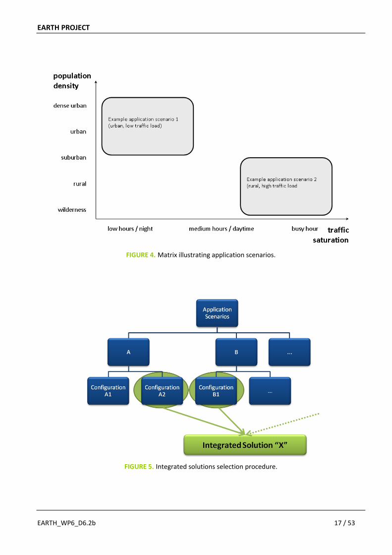
Since differing propagation conditions, traffic demands, and traffic distributions set very different requirements upon the network performance, optimal strategies on each time scale and consequently any optimal network configuration depend on the scenario under study. For this reason it is necessary to consider small-scale, short-term application scenarios, which will reflect typical and most relevant combinations of deployment and traffic scenarios as defined in [9]. FIGURE 4 illustrates the definition of the application scenarios.
For a given set of application scenarios, an integrated solution is defined as a corresponding collection of network configurations (one for each application scenario) as illustrated in FIGURE 5.
EARTH PROJECT
EARTH_WP6_D6.2b 17 / 53
FIGURE 4. Matrix illustrating application scenarios.
FIGURE 5. Integrated solutions selection procedure.

EARTH PROJECT
EARTH_WP6_D6.2b 18 / 53
In principle, a large number of different combinations of strategies, network configurations, and consequently different integrated solutions are conceivable. In order to evaluate their performance with respect to a common baseline, a reference system is defined in [9] which then also can be considered as a reference integrated solution. In short it consists of the following configuration: Macro deployment – No management – Standard RRM.
Ideally then, the energy savings of all conceivable network configurations shall be computed for each application scenario. However, it will not be feasible to compute all combinations of strategies in detailed simulations. Instead, we will first analyse general effects of interaction between EE enablers and strategies and group those into configurations that apply well for the same application scenario. These findings will then be used to derive a small number of preferred configurations to be validated in detailed system level simulations and averaged over the application scenarios to yield the overall gain of the integrated EARTH concept. The methodology for this evaluation is described in the following section.
2.2.2. Evaluation
An important challenge for the EARTH project is to evaluate the overall energy efficiency of the final integrated concept verifying that it meets the overall target of 50% energy saving. In the following, it is discussed how this evaluation will work.
The input from the conceptualization stage discussed above is a small number of preferred configurations tailored to the application scenarios. The evaluation process will be based on the EARTH E³F (see FIGURE 6) and will be a joint effort between the partners involved in this activity. Hence, multiple System Level Simulators (SLS) will be available for the evaluations of the various configurations.
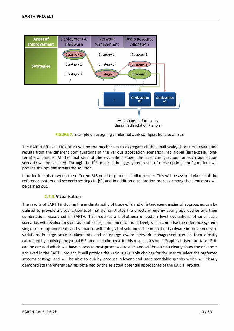
Each SLS will be responsible to evaluate a reasonably small number of configurations in small-scale, short-term application scenarios. This number of evaluations shall comprise as much similar configurations as possible to align and optimise the evaluation stage between the different platforms. For example, a SLS could be responsible for evaluating scenarios with configurations including a specific CoMP strategy, a specific new promising component, but for all the various feasible scheduling mechanisms and application scenarios (see FIGURE 7).
FIGURE 6. E3F mechanism for global scale aggregation.
EARTH PROJECT
EARTH_WP6_D6.2b 19 / 53
FIGURE 7. Example on assigning similar network configurations to an SLS.
The EARTH E³F (see FIGURE 6) will be the mechanism to aggregate all the small-scale, short-term evaluation results from the different configurations of the various application scenarios into global (large-scale, long-term) evaluations. At the final step of the evaluation stage, the best configuration for each application scenario will be selected. Through the E3F process, the aggregated result of these optimal configurations will provide the optimal integrated solution.
In order for this to work, the different SLS need to produce similar results. This will be assured via use of the reference system and scenario settings in [9], and in addition a calibration process among the simulators will be carried out.
2.2.3. Vizualisation
The results of EARTH including the understanding of trade-offs and of interdependencies of approaches can be
utilised to provide a visualisation tool that demonstrates the effects of energy saving approaches and their
combination researched in EARTH. This requires a bibliotheca of system level evaluations of small-scale
scenarios with evaluations on radio interface, component or node level, which comprise the reference system,
single track improvements and scenarios with integrated solutions. The impact of hardware improvements, of
variations in large scale deployments and of energy aware network management can be then directly
calculated by applying the global E³F on this bibliotheca. In this respect, a simple Graphical User Interface (GUI)
can be created which will have access to post-processed results and will be able to clearly show the advances
achieved in the EARTH project. It will provide the various available choices for the user to select the preferred
systems settings and will be able to quickly produce relevant and understandable graphs which will clearly
demonstrate the energy savings obtained by the selected potential approaches of the EARTH project.
EARTH PROJECT
EARTH_WP6_D6.2b 20 / 53
3. MOST PROMISING TRACKS
The EARTH project has during the first year investigated a broad variety of approaches to improve energy efficiency, so-called tracks, which typically is a concept/solution proposed and studied by one or a limited number of partners. These solutions/tracks are in depth described and studied in [10] and [11]. In order to focus on the most relevant areas, and to guide the further work in the project, a number of them have been selected for final evaluation. They are considered as the “most promising tracks” for the EARTH integrated solutions to be used for energy efficiency evaluation on system level. This holistic evaluation will lead to final assessment of the selected concepts. This chapter will describe how this selection process was carried out, what the selection criteria were, and finally also present the selected tracks sorted according to the areas “Green Networks” and “Green Radios”.
3.1. PROCESS AND CRITERIA
The purpose of the most promising track selection for the EARTH project is to assure efficient project resource utilization in the work to reach the challenging overall project goal of finding solutions to reduce the total energy consumption of mobile broadband networks with 50%.
Therefore the natural basis for prioritization of different proposals in the selection has been the individual contribution of the individual track to the 50% goal. Given that the aim is that such an evaluation should in the extension indicate the usefulness of the proposed method and actual power saving in a typical network implementation this quickly becomes a very complex and demanding task. In short the process can be described as follows:
1. Develop an energy efficiency evaluation framework, including energy efficiency metrics, reference systems and scenarios.
2. Evaluate the specified reference system in the specified reference scenarios. 3. Evaluate the proposed solutions in the specified reference scenarios in order to see what energy savings
they can bring. 4. Judge carefully what solutions are the most promising, taking into account both the achievable gains and
how often they will be valid in a real network in operation.
The evaluation methodology that has been developed in the project (E³F, [8]) is based on state of the art system simulation evaluation aggregated for a typical baseline system and traffic and deployment reference scenarios. The first step in this process was to specify common assumptions in the form of reference system and scenarios. This was done in the form of a baseline system which is the common baseline reference for the project, but also with optional system extensions [9] that provide guidance for what parameters to use when evaluating scenarios not contained in the baseline system, e.g. for relay based solutions. The next step was to complement this with realistic power models (to capture energy consumption), traffic models (to capture traffic variations over a longer period of time), and deployment models (to weight the relevance of the specified reference scenarios). This assures that the total energy usage in a typical network is addressed and should also prevent that unnecessarily much resources are spent on optimizing infrequent or very rare scenarios or situations.
The evaluation of the specified reference system in the specified reference scenarios are reported in [8], and the main conclusion out of that is that what really counts when improving overall energy efficiency of a cellular mobile broadband system is to focus on low load or even no load scenarios. In fact, the evaluation showed that in average less than 10% of the available radio resources are used for data transmission, indicating that these low load and no load situations is the area where the largest gains are to be found, and that solutions focusing on such situations should be prioritized in the selection process.

EARTH PROJECT
EARTH_WP6_D6.2b 21 / 53
The next step in the process, i.e. to evaluate the proposed solutions was a real challenge. Since the evaluations involve quite demanding system simulations (which is a necessity to obtain credible results and draw fair conclusions) it was apparent that not all partners possess the proper tools which would make it possible to perform a full evaluation based on the E³F. However, in order to nevertheless get an evaluation based on the principles that the project has agreed on for the E³F one way has been for the partners to base their evaluation on knowledge and parameters which has been obtained from the evaluation of the specified reference system (see the previous step above). The E³F consists of several aggregated scenarios and some of the solutions proposed by the partners only addressed part of the aggregated reference scenario, e.g. low or high traffic scenarios. Therefore, it has also been possible for a partner to only take the more limited effort to perform system simulations in the for the proposed solution most relevant and favorable scenario. By comparing afterwards with the reference system evaluation in the reference scenarios this still give a good idea of the total energy saving obtained for the solution with the E³F methodology.
In the end, a project-wide workshop was held in order to carefully judge what solutions are the most promising. In the workshop, all solutions/tracks were presented and discussed in detail with the aim to reach a common conclusion regarding what solutions have shown the most promising potential. In order to guarantee a high quality selection, the workshop was prepared by a review process across the task and workpackage structure of the project where senior researchers and technical experts reviewed tracks in which they had not directly been involved during the work. Also some partners involved technical experts in the area, but not working in the project, in order to get as relevant and good decisions as possible.
The outcome of the selection process is reported in the following sections, divided according to the main areas “Green Networks” and “Green Radios”. In total 47 solutions for improving energy efficiency were proposed and studied during the first year of the project. 37 of these were selected as “most promising”, while the activities related to 10 of them were considered as completed and will not be pursued further in the project.
3.2. GREEN NETWORKS
In the field of Green Networks, the solutions of 23 activities (so-called tracks) were analyzed. 19 activities were selected as most promising tracks for the EARTH integrated solutions, while 4 activities were completed. In the first half of the project, the concepts behind the activities were organized around 7 different topics allowing a preliminary analysis of inter-dependences of these concepts meanwhile providing a first step towards integrated solutions by the harmonization of the activities on the same big topics. The seven topics are as follows:
Optimal mix of cell sizes focusing on the applications of smaller cell sizes with 2 tracks selected as most promising.
Relays focusing on splitting the transmission into smaller hops with 2 tracks selected as most promising.
Multi-RAT deployment focusing on splitting power, selecting active elements and LTE roll-out plans with 3 tracks selected as most promising.
Base station cooperation focusing on cell-edge communication with 3 tracks selected as most promising.
Adaptive network reconfiguration focusing on the adaptation according to daily traffic variation with 4 tracks selected as most promising.
Radio resource management focusing on combination of RRM and DTX, traffic dependent multi-RAT coordination and multi-cell COMP with 5 tracks selected as most promising.
Future architectures focusing on such questions and assumptions which are beyond the capabilities of the legacy and LTE systems. Thereby these tracks were not included into the most promising track selection process and these concepts will be analyzed in deliverables [19] and [20] on green network technologies later on. Nevertheless, some of these concepts will be introduced at the end of this section.
EARTH PROJECT
EARTH_WP6_D6.2b 22 / 53
3.2.1. Optimal mix of cell sizes
In this topic, we have analyzed the nontrivial impact on total power of shorter Inter-Site-Distance (ISD) indicating shorter transmission distances and less transmission power. That is, we have analyzed the potential in smaller cell sizes, HetNet deployment and using mix of cell sizes. We have found that the potential energy saving gain depends very much on power model and traffic scenario. Furthermore, we have found that small cell are not always the best but only for high traffic. In this topic we have selected the following two tracks as most promising.
In the first track, heterogeneous deployments with small cells at the edge of macro cells were applied to tailor the density of base stations to the required capacity per area. We have found that there is an optimum inter-site distance (ISD) of macro base stations depending on traffic density if the maximal power of the macro base station scales with the size of the cell1. We have found that adding micro cells is advantageous in case of busy hour or inhomogeneous traffic (like hot spots). In such cases up to 25% area energy saving can be achieved and the micro cells are preferably operated with energy aware network management. (See [10], section 2.1.2).
In the second track, the mix of macro cells and smaller cells is applied to an inhomogeneous traffic pattern with daily variation of hot time zones of much higher data rate requirement. We have found that even with two separated zones, the cell size can be optimized based on the temporal traffic distribution and some of the base stations in the sparse zone can be switched off thereby resulting in up to 20% energy saving gain with the proper selection of the separated zones with different base station density. (See [10], section 2.1.3).
We have also studied the energy efficient macro cell deployment in urban areas, i.e., to find the optimal cell size at given capacity and coverage conditions. We have found that the power model is the main factor of the optimization and the power offset at zero load has the strongest impact on the results. Since this power offset is relevant in the current EARTH macro cell power model (2010) [8], the fewer the nodes (or the larger the cells) the better results we have, which is the same principle that is used today. Thereby, it has been decided to complete the activity on this track.
3.2.2. Relays
Relays split the transmission into smaller hops, where the link between base stations and relays may have better channel quality compared to the direct communication with the user terminals. In this topic we have compared two-hops half duplex transmission with multi-cast cooperative scheme and hybrid relaying by combining Amplify-and-Forward (AF), Decode-and-Forward (DF), Compress-and-Forward (CF) techniques. We have found that 2 hop relays are more efficient than cooperative multicast and the hybrid scheme of CF/DF beneficial for large cells. In this topic we have selected the following two tracks as most promising.
In the first track, 2 hop relays (of Type 1, visible to the terminals) and the multicast cooperative scheme of relays (of Type 2, transparent nodes) were compared. We have found that relays can improve the energy per bit used in the system because of the increased system capacity. In this respect 2 hop relays are more efficient than the multicast scheme because of the utilization of the low power link between the relay and the terminal; and 2 hop scheme provide 6-12% gains in energy per bit for high traffic scenarios. (See [10], section 2.2.1).
In the second track, hybrid relaying was analyzed based on the combination of AF, DF and CF techniques. We have found that the direct transmission is more efficient when the transmission range is small, i.e., less then 100m, which is a practical limit for relay deployment in general. For large transmission ranges (above 300m corresponding to 450m ISD ~ typical urban macro ISD according to 3GPP [14]) the CF/DF based hybrid strategy is the best choice in large cells with up to 30% gain in energy per bit over standalone DF technique (typically applied today). (See [10], section 2.2.2).
1 If not, then the fewer macro base stations are in the system, the less energy is needed as in case of general network
planning. (See [10], section 2.1.1).
EARTH PROJECT
EARTH_WP6_D6.2b 23 / 53
We have also analyzed the in-building relaying scenario with closed-form approximation of the MIMO AF system capacity and energy efficiency. We have found that such a solution is “limited” to the case of high indoor user fraction with LOS quality connection to the relay node with direct sight to the serving base station, i.e., in most of the cases it is easier to cover indoor users by femto cells. Thereby, it has been decided to complete the activity on this track.
We have also compared single-hop multicasting and multi-hop multicasting via relays. We have found that such a problem formulation and results give low gain and have too many uncertainties to be a promoted solution for deployment strategies. Thereby, it has been decided to complete the activity on this track and focus on network coding based energy reduction for multicasting in the topic of future architectures.
3.2.3. Multi-RAT deployment
In this topic, we have examined when multi-RAT systems can perform more energy efficiently than single-RAT systems. We have analyzed dual and multi-RAT operations, compared legacy and LTE deployment schemes as a function of traffic and frequency bands, and compared different rollout plans for LTE with potential site sharing. We have found that combining different RATs on different frequency bands can provide higher bandwidth and better coverage compared to a single-RAT system, and the selection of deployment schemes for LTE rollout plans are greatly depending on spatial and temporal traffic evolution. In this topic we have selected the following three tracks as most promising.
In the first track, the deployment of single-RAT base stations is compared with deploying two radio interfaces into base station positions. These latter could model different technologies (like 3G and LTE), or two interfaces of the same technologies as well (LTE deployed in different bands, or LTE carrier aggregation). The results confirmed that the more bandwidth should be deployed onto the lowest carrier frequency possible. Moreover, additional gains can be realized (over the gains coming from the broader bandwidth and different carrier frequencies) if we assume power saving of co-location, i.e., more RATs are deployed over the same base station platform at the same location. (See [10], section 2.3.1).
In the second track, we have compared legacy (WCDMA/ HSPA) and LTE networks in case of different traffic demand levels and user densities. We conclude that in case frequencies in the lower bands become available (e.g., GSM is gradually phased out), then these frequencies should be reallocated to LTE. However, if legacy RATs should be kept or coverage/conversational services are enough to be provided, LTE should be primarily deployed in urban areas, where capacity is needed. We should also note that micro site deployment is more energy-efficient than macro site deployment if sufficient quality is granted for users (e.g., throughput enough for HDTV even in cell-edges) [8]. (See [10], section 2.3.2).
Note that these two tracks and studies form the basis of adaptive network reconfiguration techniques presented in Section 3.2.5.
In the third track, the gradual deployment of new LTE base stations in addition to the still operating legacy RATs is analyzed from energy efficiency point of view. When defining the capacity distribution among RATs, one has to take into account traffic demand increase, the different types of UEs available and a possible reuse of legacy sites. We found that the ratio of existing 2G and 3G devices has impact on the LTE deployment phase, we have compared 50:50, 10:90 and 90:10 ratios. The results show that site sharing could provide up to 10% gain in energy per bit, the highest gain can be achieved in a balanced (50:50) multi-RAT environment. (See [10], section 2.3.3).
EARTH PROJECT
EARTH_WP6_D6.2b 24 / 53
3.2.4. Base station cooperation
In this topic, we have examined how base station cooperation can be utilized in areas where the link quality is poor or the interference from other users is strong, that is, how to improve the cell-edge communication. We have analyzed fractional frequency reuse (FFR) schemes and the selection of feasible groups for cooperation. We have found that frequency reuse is more efficient in case of high traffic demands. We have also found that cooperating with more than three BS is unlikely to improve the energy efficiency and the cooperation is more effective if the feasible groups of base stations to cooperate are calculated in advance and not on demand. In this topic we have selected the following three tracks as most promising.
In the first track, we analyzed how to eliminate non-controlled interference among adjacent cells by coordinating the FFR parameters between neighbouring base stations. An adaptive strategy is proposed to dynamically follow traffic load and the resource allocation strategy. The coordination between base stations is ensured through a DL interference indicator, i.e., the Reduced Narrow Band Transmit Power (RNTP). We have found that the adaptation of the FFR parameters to the traffic load and to the RNTP indicator of neighbouring cell can give up to 10% gain in energy per bit over a static case (based on fixed FFR parameters and pessimistic estimation of signal level of interferers). (See [10], section 3.1.1).
In the second track, we have investigated how much energy can be saved by applying the network MIMO as a function of cooperating base stations. Such CoMP schemes generate additional backhauling power and have effects in the channel estimation and MIMO processing of a base station. This latter has a strong impact since it scales quadratically with the cooperation size. For 1% share of MIMO processing from the overall processing and a cluster size of 3 (best in case of co-operation of 3 co-located BSs), network MIMO can provide 10% gain in energy per bit for site distances up to 500m and more than 15% gain in energy per bit for site distances larger than 1000m. (See [10], section 3.1.4).
In the third track, we have in investigated how to reduce the system energy consumption of the network MIMO by pre-selecting the set of base stations which are eligible for cooperation. In a typical CoMP system, not all the BSs selected for cooperation can join the cooperative cluster in practice because of possible backhaul limitations like capacity or latency. By predicting the set of BSs which can actually join the cooperative cluster we can avoid useless CSI estimation for those who cannot take part, as well the related MIMO processing and eventually user data sharing over the backhaul. Depending on the number of active users and their throughput requirements, in many circumstances the desired wireless cluster is infeasible. In such cases the pre-calculation can provide up to 15% gain in energy per bit in average. (See [10], section 3.1.3).
We have also studied distributed multiple-input multiple-output (DMIMO) system to improve cell edge communication focusing on the extension of Shannon theory for energy efficiency analysis. We have found that cooperating with more than three BS is unlikely to improve the EE, that backups other simulation based calculations of other tracks. Gains can be achieved if the two helping BSs are not farther than the serving BS and in that case the radiated power at cell edge can be halved providing 5-10% gain in energy per bit. We have decided that further analysis of fundamental trade-off for DMIMO communication will be carried out in the topic of future architectures together with other related activities.
3.2.5. Adaptive network reconfiguration
In this topic, we have analyzed how to change the network configurations adaptively to the daily variation of the traffic by basically reducing the number of active network elements. We investigated areas already dimensioned to serve peak capacity, i.e., highly populated areas, where we have found that standby schemes like changing sectorized cell to omni cells, switching of complete sites even in different RATs are effective techniques. We also investigated less populated or rural areas tailored to provide coverage, where we have found that cell micro DTX and bandwidth adaptation are effective techniques. In this topic we have selected the following four tracks as most promising.
EARTH PROJECT
EARTH_WP6_D6.2b 25 / 53
In the first track, we have investigated how to adaptively set the bandwidth utilization of the network according to the dynamic daily variation of the traffic. In order to eliminate the impact on QoS, we kept the power density per resource block constant, meanwhile keeping the power amplifier more closely to its most efficient operation point. I.e., by reducing bandwidth, less resource blocks are used for scheduling less user data. We have found that such a technique is effective for slowly changing non-bursty traffic like streaming dominated traffic providing 20-30% area energy saving. (See [10], section 3.2.1).
The other three tracks in this topic are connected to each other and can be considered as a joint group of tracks analyzed in close cooperation of four partners. Thereby the different activities are presented in the order of widening the scope.
In the second track, we have investigated how to eliminate the underutilization of the networks in low traffic hours by reducing the number of active base stations dynamically by changing the network layout. When the traffic load decreases, we leave only one from four cells or one from nine cells in operational state with higher power transmission to maintain coverage, i.e., ISD can be doubled or tripled by such a technique. We have found that dynamic adaptivity needed to follow local fluctuations of the traffic and this technique provides 25% area energy saving. (See [10], section 3.2.2).
In the third track, we have adapted the “network density” according to the variation of traffic beyond reducing the number of active base stations dynamically by selecting also which RAT to operate and whether a macro or micro cell operation serves the user demands with less energy. We have found that the proper selection of macro vs. micro cell layers and their density provides 25% area energy saving and the selection of the right frequency bands for different RATs, i.e., operating LTE in low frequency bands provides more than 40% additional energy saving. (See [10], section 3.2.4).
In the fourth track, we have classified several network management actions about where and when they can be applied. Additionally to the second and third tracks, we have investigated the effect of changing sectorized cells to omni cell, change HetNet layout (switching on/off macro/micro cells) and micro sleep modes (cell DTX). We have found that introducing cell DTX beyond rearranging load among cells and switching of cells can double the gains on countrywide average, that is, it possible to reach 25-50% or even more area energy saving for broadband services with the combination of available techniques. (See [10], section 3.2.3).
3.2.6. Radio resource management
In this topic, we have analyzed potentials of radio resource management, especially how to reduce the energy consumption based on packet scheduling techniques. First of all we have analyzed the energy awareness of SOTA RRM scheduling algorithms and the trade off between energy efficiency and spectral efficiency. We have also investigated the combination of DTX and power control, vertical handover based on traffic and channel info, and multi-cell scheduling for CoMP. We have found that RRM techniques perform better in case of low load, meanwhile power control is a good technique even for high load. In this topic we have selected the following five tracks as most promising.
In the first track, we have started with the analysis of SOTA packet scheduling algorithms from energy efficiency perspective with a baseline of round robin. We have found that Maximum Carrier over Interference (Max C/I) has good performance in terms of both spectral and energy efficiency (60% gain in output RF energy saving), the counterpart is its very low fairness (>50% loss in Jain’s fairness index *21]). So proportional fair (PF) is a good compromise with >20% RF energy saving and >10% better fairness with respect to the round robin case. Further investigations are towards incorporating cell DTX and dedicated solutions for cell edge and cell center users. (See [10], section 4.1).
In the second track, the trade off between energy efficiency and spectral efficiency was further analyzed. The focus of the investigation is to change the modulation and coding scheme (MCS) chosen by the users and decrease the power level to provide lower, but still enough SINR for the QoS target. That is, the transmission
EARTH PROJECT
EARTH_WP6_D6.2b 26 / 53
of the non-prioritized packets can be delayed or slowed to save energy in low load scenarios. We have found that for voice users 10% energy per bit can be saved compared to MCI and Earliest Deadline First (EDF). (See [10], section 4.2).
In the third track, we have investigated how to reduce energy consumption by adjusting the system transmissions according to (traffic) load, channel states and base station generation. An effective solution controls the transmit power per resource element meanwhile balances between transmission duration and transmit power, and utilizes DTX modes of base stations. We have found that power control is the best solution for high load scenarios and DTX is most effective in low load scenarios. This approach can provide 30% area energy saving. (See [10], section 4.3).
In the fourth track, we have investigated how to extend RRM techniques to manage different traffic types in a multi-RAT environment. Based on cost functions including control overhead and power consumption, the optimal RAT can be identified for given traffic types (like web browsing, voice, file download, etc.) and the management system can migrate such users to the most suitable RAT via vertical handovers. We have found that these techniques works better for low load scenarios and can provide up to 13% gain in energy per bit. (See [10], section 4.4).
In the fifth track, we are analyzing how to provide an optimal resource allocation for a multi-cell system by sequential coordinated resource sharing between interfering sectors of 3 adjacent BSs. Current results are available for a multi-user singe-cell configuration providing 5-30% gain in energy per bit compared to best-sum rate allocation strategy in the downlink depending on the cell size. We have found, that the smaller the cell, the larger gain can be achieved (5% corresponds to typical rural ISD, while 30% to typical urban ISD [14]). (See [10], section 4.5).
3.2.7. Future architectures
Despite the success of the existing cellular architecture, there remains great potentials for improvement in several directions resulting in energy saving. In order to add more “flexibility and intelligence” to the systems, we need to adapt, re-plan or even rethink the existing systems. We are investigating how to de-couple data and system information, i.e., let go off the fix idea that the coverage of BCH and data channels must be the same.
We are also investigating application of multi-hop extension of existing system focusing on coverage and capacity extensions in both uplink and downlink limited cases and the corresponding routing protocols to control such a mobile system.
We also analyze the concept of handling packets as "bits" on finite field operations, also known as network coding (NC). Different aspects of NC are analyzed for energy saving including comparison of NC vs. retransmissions, application of physical layer network coding in two-way relay systems and packet-combining schemes for multicasting.
Taking forward the concept of cooperative techniques among the network nodes (see Section 3.2.4) can yield significant performance benefits since nodes can coordinate their decisions and exploit common information. The main focus is the further analysis of MIMO for energy efficiency. This activity includes i) the analysis of fundamental trade-off for MIMO communication with various antenna elements including distributed antenna systems (DAS); ii) cooperative MIMO for providing higher throughput for users instead of turning on sleep mode antennas in low traffic hours; and iii) network MIMO supported by backhauling based on low energy passive optics and cooperation of traditional radio over fiber based CoMP schemes and smart active antennas.
EARTH PROJECT
EARTH_WP6_D6.2b 27 / 53
3.3. GREEN RADIOS
On Green Radios 24 individual solutions have been analyzed. 18 will be considered as most promising tracks for the EARTH integrated solutions while the activities on 6 solutions have been completed. During the first half of the project the individual concepts considered as most promising have been grouped into 9 different topics allowing to consider in a first step the inter-dependences of the concepts or to define in some cases a first level of integrated solutions. These nine topics are the following:
Transceivers for macro-cell base stations focusing on energy efficient hardware concepts for macro cell base stations.
Transceivers for small-cell base stations focusing on corresponding hardware realizations for small cell base stations.
Low loss antennas focusing on designing more efficient printed antennas.
Beamforming and active antennas focusing on cell-specific and user-specific beamforming.
MIMO transmission focusing on adaptive use of MIMO in order to save energy.
Bandwidth adaptation focusing on adapting the system bandwidth to the traffic demand.
Cell DTX focusing on component deactivation in time periods without signal transmission.
Adaptability to system dynamics focusing on saving energy in high traffic periods.
Retransmission schemes focusing on reducing the number of packet retransmissions thereby avoiding energy wastage.
3.3.1. Transceivers for macro-cell base stations
Four tracks are related to the topic Transceivers for Macro-Cell Base Stations and define a load adaptive transceiver system. It is build up by the integration of a power amplifier, a dedicated power supply unit, a small signal RF transceiver and the digital transceiver part.
The power savings of the Adaptive Energy Efficient PA is based on operating point adaptation to the signal level minimizing the consumed power and on the deactivation of amplifier stages during time periods without signal transmission. These approaches support the strategy to minimize the power consumption for medium and low traffic load by optimizing the instantaneous energy efficiency of the hardware components for variable load. The theoretical estimations, done for a 40W Doherty PA, show up to 50% reduction of power consumed by the amplifier for low signal level and near to 80% reduction during deactivation periods (See [11], section 4.2.3).
An adaptive power supply unit enables the adaptation and deactivation of the transceiver components and especially of the PA and minimizes its power consumption related to the variable power supplied to the components (See [11], section 4.2.4).
As a Small Signal RF Transceiver a dual power mode feature has been proposed, which allows the deactivation of a part of its components during time periods of no signal transmission. The power consumption is considered as independent from the signal level. For the deactivation state 37.5% reduction of consumed power has been estimated in case of a single receiver solution and 29% for a dual receiver (See [11], section 4.2.2).
A Digital Signal Processing and Control (DSPC) component has been proposed as the digital transceiver unit, which provides in addition to the state-of-the-art signal conditioning features (like digital predistortion and clipping) the control signals to the transceiver components for their adaptation and deactivation. The DSPC provides the interface of the transceiver to the base station base band components and receives the layer 1 and 2 information required for component adaptation. By analyzing the incoming signals, required signal parameters are extracted and used in addition to the layer 1 and 2 information for defining the operations
EARTH PROJECT
EARTH_WP6_D6.2b 28 / 53
required to adapt the components to the signal level. Such operations relate to signal conditioning, like adapting the clipping algorithm to the average signal level; to definition of control signals required for component adaptation; and to sending the control information to the components for initiating their reconfiguration (See [11], section 4.2.1).
All four tracks contributing to the transceiver for macro-cell base stations have been selected as most promising as they define together an integrated transceiver solution which provides significant power savings and performance information in terms of power characteristics to be used for the evaluation of power saving concepts acting on link and system level.
3.3.2. Transceivers for small-cell base stations
Five tracks are related to the topic Transceivers for Small-Cell Base Stations for realizing a load adaptive performance addressing the BS component chain from the baseband to the antenna (See [11], section 4.3).
On base band processing for pico base stations, the usage of ASIPs with implementation oriented optimizations has been proposed instead of state-of-the-art FPGA solutions. For different modulation schemes and coding rates a potential reduction of energy required for base band processing between 68% and 92% has been estimated (See [11], section 4.3.1).
Different mechanisms have been evaluated for reducing the power consumption of small signal RF transceivers of pico base stations. Based on power characteristics versus signal load, the power consumption for different traffic loads has been determined. While a moderate 15% reduction of consumed power is shown at maximum traffic, the savings increase significantly for lower traffic situations. Sleep mode operations shows up to 65% power reduction for minimum traffic situation. Capacity adaptation provides additionally about 20% savings for minimum load, while SiNAD adaptation shows up to 10% power reduction in addition at traffic loads close to 50%. The evaluated solutions take benefit from a trade-off between transceiver performance and power consumption by operating the transceiver at the limit of the required signal quality to determine the maximum range for power savings (See [11], section 4.3.2).
The potential on energy savings in pico base stations by using a tuneable matching network for load adaptation for power amplifiers has been estimated. This solution enables the load modulation concept for energy efficient PAs providing power reductions, which are moderate at low signal loads (15%) but increases up to 40% for maximum load. These results are based on the assumption of 1dB insertion loss for the tuneable matching network, a parameter which still shows a significant uncertainty (See [11], section 4.3.4).
For decreasing the power loss on the transmitter path between PA and antenna a simplified connection has been analysed taking benefit from isolated transmit and receive antennas. The waiving of duplexers allows the usage of filters with more relaxed requirements leading to lower insertion losses. The optimization of antenna efficiency and impedance matching is done by taking care on the trade-off between the impedance level of the PA output and the antenna reference impedance on one side and the complexity and losses of the matching network on the other side. These nonconventional approaches together show the potential to reduce the signal losses by 1 to 3 dB (See [11], section 4.3.5).
An Adaptive Energy Efficient PA has been proposed for small-cell base stations based on the concept described above for macro-cell base station. An adaptive 0.25W PA (class-AB) solution has been analyzed showing up to 50% reduction of power consumed for low signal level and near to 80% reduction during deactivation periods (See [11], section 4.3.3).
All five tracks contributing to the transceiver for small-cell base stations have been selected as most promising as they define together complementary hardware solution which provides significant power savings and performance information in terms of power characteristics to be used for the evaluation of power saving concepts acting on link and system level.
EARTH PROJECT
EARTH_WP6_D6.2b 29 / 53
3.3.3. Low loss antennas
Evaluations for improving the efficiency of printed antennas provide a solution for the topic on Low Loss Antennas. Taking benefit on new low loss dielectric materials and taking care on the element configuration and inter-element spacing, improvements of the efficiency from 70-90% (state-of-the-art) to 90-95% are expected (See [11], section 4.4). This track has been considered as most promising as it provides a tangible loss reduction in planar antennas without inter-dependencies to other solutions.
3.3.4. Beamforming and active antennas
Two tracks are related to the topic Beamforming and Active Antennas, focusing on cell specific and user specific beamforming.
The first approach is based on a reconfigurable antenna system. By assessing the user distribution in the cells, “hotspots” can be identified and served with higher antenna gain in a prioritized way by accepting the disadvantage of lower antenna gain in the rest of the cells. The expected overall benefit increases with the hotspot probability showing up to 50% higher system throughput and up to 35% power reduction in the base station for up to 100% hotspot probability (See [11], section 2.2.1).
The second approach on the area of beamforming takes benefit from active antenna systems. The increased number of base station antennas given by antenna arrays enables a higher flexibility for beamforming and higher antenna gain. This leads to up to 51 % increase on average cell spectral efficiency [bps/Hz/cell] for BF4x2, a configuration with 4 antennas at the base station and 2 at the user equipment. The user spectral efficiency @ 95% [bps/Hz] increases by up to 43% for BF4x2. These efficiency improvements are related to a SIMO 1x2 configuration with a single antenna at the base station. These figures show the potential to decrease the transmit power leading to decreased power consumption (See [11], section 2.2.2).
Both tracks have been selected as most promising due to their potential on reducing the RF power transmitted by the base stations.
3.3.5. MIMO transmission
Three tracks related to the topic MIMO Transmission with the aim to limit the waste of power due to MIMO have been selected. The considered design and selection of optimum precoding matrixes, duty-cycling (frequency/time) and resource allocation strategies allow to maximize the performance and to improve the energy efficiency. SISO/MIMO selection is used for maximum spectral and power efficiency.
Investigations compare the power consumption of pico base stations in SISO and 2x2 MIMO configuration for different modulations and coding rates by considering time-domain and frequency-domain duty-cycling. The considered field of parameters delivers a power consumption span of factor 5.5 for SISO and 7 for MIMO for a targeted throughput (See [11], section 2.3.2).
Novel precoding design and scheduling techniques for achieving both higher MIMO gains and lower power consumption (e.g. via lower PAPR) show up to a factor of 4 of gain comparing to conventional MU-MIMO (See [11], section 2.3.1).
Further investigations on energy efficient MIMO schemes and resource allocation led to initial results showing for dense urban medium traffic 31% energy efficiency improvement when applying SIMO,CQI instead of SU-MIMO,CQI, while for dense urban high traffic about 10% with 4x2 MU-MIMO, CSI is expected.
EARTH PROJECT
EARTH_WP6_D6.2b 30 / 53
These activities on MIMO application will provide MIMO configurations for optimized energy efficiency for avoiding power wastage due to arbitrary configurations which could lead to a large fluctuation of power consumption. Therefore these three tracks have been selected as most promising to be considered for the evaluation of integrated solutions.
In addition to these, relative MIMO gain has been investigated as a function of distance for different channel models, system bandwidths, modulation techniques and coding schemes. A range of 12dB on signal to noise ratio improvement has been determined for 4x4 MIMO compare to SISO for an ETU70 channel model, 20 MHz bandwidth, 64QAM, 3/4 coding rate and 30 to 100m BS/UE distance. A proper SISO/MIMO mode selection according to the required data rate has been proposed for exploiting the energy efficiency potential of this 12dB range of SNR (See [11], section 2.3.1). As these aspects are covered by other tracks of the MIMO topic shown above, it has been decided to complete the activity on this track.
Furthermore, a RF-MIMO concept has been considered with regard to the power consumed in a pico base station for SISO, 2x2 MIMO and 4x4 MIMO applications and compared with base band MIMO solutions. Due to a simpler hardware, for RF-MIMO 20% reduction for 2x2 MIMO and 50% reduction for 4x4 MIMO has been estimated compared to the reference base band case. The applicability of this solution is restricted to beamforming while spatial and time multiplexing is not feasible (See [11], section 4.3.6). Due to these restrictions it has been decided to complete the activity on this track.
3.3.6. Bandwidth adaptation
The topic Bandwidth Adaptation is based on a stepwise adaptation of the bandwidth or capacity usage to the required average traffic load. An optimized scheduling, combined with an adaptation of hardware components to the signal level, leads to up to 21.4% average reduction of base station power consumption for dense urban traffic, while for suburban traffic up to 29.3% are expected. This performance has been evaluated for 24 hour traffic on the basis of long-term traffic models (See [11], section 3.4). Due to its potential on energy efficiency improvement, this track has been selected as most promising to be considered for the evaluation of integrated solutions.
3.3.7. Cell DTX
In the topic Cell DTX, the potential on energy savings taking benefit from component deactivations in time periods without signal transmission is evaluated. The strategy there is to maximize the portion of these idle time slots by using always the maximum bandwidth and by reducing the amount of signalling when no data is transmitted. For micro DTX, the LTE Rel-8 compliant version, provides 17-19% power saving in average, while for short DTX and long DTX, which requires modifications in the LTE standards, even higher savings are expected (See [11], section 3.5). Due to its potential on energy efficiency improvement, this track has been selected as most promising to be considered for the evaluation of integrated solutions.
3.3.8. Adaptability to system dynamics
The evaluations on the topic Adaptability to System Dynamics in Small-Cells shows that, in contrast to macro base stations (see below), for pico base stations important gains could also be achieved for higher traffic load by carefully choosing the transmission scheme that best adapts to the channel conditions with low power consumption. Since the number of users is reduced, the system is more capable of finding an appropriate scheme for each user at a time. The energy consumption [W] of the base station versus traffic load [Mbps] has been evaluated as a power consumption characteristic on link level based on short-term traffic models. 18% of power reduction is expected for 48 Mbps and 59% for 5Mbps (See [11], section 3.6). Due to its potential on
EARTH PROJECT
EARTH_WP6_D6.2b 31 / 53
energy efficiency improvement, this track has been selected as most promising to be considered for the evaluation of integrated solutions.
The energy gains achievable at the base band have been analysed by adapting to the channel conditions and using the best transmission scheme. This includes the analysis of the trade-off between energy consumption of CSI estimation accuracy and the performance. Up to 31% reduction in energy per bit has been evaluated for micro base stations and up to 35% for macro base stations. But this does not translate into power savings on system level as no correlation to power per area could be observed (See [11], section 3.7). Due to the lack on power reduction it has been decided to complete the activity on this track.
3.3.9. Retransmission schemes
Three tracks have been investigated for finding out the potential on energy efficiency improvement on the area of retransmission. Modified retransmission scheduling shows only a minor reduction of number of retransmissions and insignificant impact on power consumption. A gain of about 10-15% is expected due to parameter optimization of HARQ, like adaptive modulation and coding. By defining the optimal activation time for minimum energy per bit, a potential energy reduction in J/bit of up to 40% has been estimated which translates only partly into power savings (See [11], sections 3.2 and 3.3). As for variable load scenarios these power savings are expected only during transmission, this means only during a minor part of the day, for the whole system operation only a minor energy efficiency improvement is expected. Therefore, it has been decided to complete the activities on these three tracks and the whole topic as such.
EARTH PROJECT
EARTH_WP6_D6.2b 32 / 53
4. CONCEPTUALIZATION AND IDENTIFICATION OF DRAFT INTEGRATED SOLUTIONS
This chapter will provide a few draft integrated solutions based on the most promising tracks being studied in the EARTH project. So far the work is limited to the conceptualization stage (see Section 2.2). Energy efficiency enablers are mapped to the time scale they operate at, and towards application scenarios. Then strategies are defined, and a few promising configurations are identified. In the chapter, initial ideas on how to adapt between configurations for different application scenarios are also given (Section 4.3).
4.1. OVERALL DESIGN CONSIDERATIONS
There are two main quality expectations towards mobile telecommunication systems, namely, high transmission speed and good coverage. The cost of network installation and operation often leads to a compromise in service quality, and it is often difficult to meet these requirements simultaneously. With the rapid traffic growth, the energy consumption of networks is an increasing part of the operation costs, but it should be capped at some point. At the same time, any technique, which aims to lower the power consumption of a network, should not result in noticeable service-quality degradation.
Today’s broadband data networks are typically dimensioned to a guaranteed minimal data rate, which the service provider intends to fulfil over the entire service area even in the busy hours. As a result of spatial and temporal traffic fluctuations, networks as a whole operate with substantial resource redundancy especially at night time.
There are two areas, which should be in focus regarding potential energy savings: 1) in case of transmitting, the transmission should be as efficient as possible, and 2) in idle periods, the network should use only the minimal power necessary to maintain service readiness. In densely populated areas, the emphasis is on transmission efficiency, while in rural areas, the emphasis is on low-power modes. It does not mean, however, that the two objectives cannot be targeted simultaneously or that different energy saving techniques cannot be combined.
4.2. ENERGY EFFICIENCY ENABLERS FOR DIFFERENT NODE TYPES AND DEPLOYMENT AREAS
Throughout the network and over the different deployment areas different types of BS nodes are deployed. According to the role of a particular radio node in the network, different energy-saving techniques and their combinations can be applied. Typically, the radio nodes can be classified as coverage and capacity nodes. The main responsibility of coverage nodes is to provide broadcast, paging and RACH/FACH services over wide areas to mobile users. Such nodes are placed typically on the multi-RAT macro sites. On the other hand, capacity nodes can be defined as those nodes that may not be needed in connecting users to their mobile service provider, yet these nodes are there to carry high-bitrate data services. In such classification, a GSM macro cell can be a coverage node, and overlapping 3G or 4G cells can be capacity nodes. The service of coverage nodes should be available anywhere and anytime, while that of capacity nodes should be available promptly on demand.
Energy-efficiency enablers that improve the radio links in general and applicable at any radio node
Eliminating feeder and antenna losses, TMA, TRX integrated in antenna on the base station side – the industry is already moving in this direction. EARTH EE enablers in this area are e.g. active antennas and low loss antennas.
Improve power efficiency of subsystems, PA, baseband, power supply, cooling, signal load adaptive transceivers, etc. – in general, technology competition leads to smaller, lighter and more power efficient products, which could be manufactured easier and sold at lower price. This process indirectly leads to less
EARTH PROJECT
EARTH_WP6_D6.2b 33 / 53
expensive sites (both in acquisition and maintenance) and more power-efficient deployments, as well. EARTH is developing macro-cell as well as small-cell hardware for this purpose.
Relays, repeaters as coverage extension in hard to backhaul area or filling coverage problems – techniques, which significantly improve field coverage at the targeted locations without new backhaul links. Today cost saving drives the application of these nodes, but they have a positive impact on the energy efficiency of networks, especially if they also employ energy saving techniques.
Antenna system at the mobile terminal – improving the MIMO and multi-band capabilities of terminals opens the way towards various forms of energy efficiency enablers on the network side as well. However, mobile terminal improvements are out of the scope of EARTH.
Optimization of off-grid sites, alternative source of power, solar, etc., optimizing diesel generators and battery backup – these are energy-efficiency enablers, which are especially important in networks of the 3rd world, even though not considered by EARTH.
Energy-efficiency enablers for coverage nodes
The coverage nodes provide the adequate field strength for the guaranteed service at cell edges in case of low traffic. If the traffic load increases and the guaranteed service level cannot be provided, then additional radio resources on the coverage nodes should be activated or capacity nodes should be turned back to full-power mode.
Typically umbrella macro cells are responsible for providing coverage. However, distinction also has to be made between rural and urban macro cells.
There are vast, sparsely populated areas in some European countries. These areas can be best covered by large macro cells operating in a low frequency band if available. It can be assumed that these cells operate at low traffic and interference-free in most of the time. So here those types of energy efficiency enablers should be applied that do not degrade signal-to-noise ratio. Since the typical bottleneck on the radio side is uplink in 3G and 4G networks, therefore the uplink should be the target of optimization.
On the other hand, urban macro cells are typically limited by interference in the busy hours. Therefore interference mitigation techniques in busy hours and power-efficient cell DTX or bandwidth adaptation techniques at times of low cell utilization should be employed. It is essential that the macro base station maintains its coverage while it operates in energy-saving mode, but since interference is also lower at low utilization periods, weaker signal levels than the ones in busy hours can be typically still tolerated. EARTH energy efficiency enablers suitable for coverage nodes are:
Cell micro DTX – maintains the coverage capability of cells, see above.
BW adaptation – an energy efficiency enabler, which operates power amplifiers at traffic-optimal operating point, while improves or at least maintains the coverage capabilities of cells. It combines well with ICIC, or in general, base station cooperation schemes.
Antenna reconfigurations, beamforming – see above.
Base station cooperation, multicell scheduling, ICIC, signal combining – energy efficiency enablers that in certain situations can be used to reduce the needed transmit power.
Energy-efficiency enablers for capacity nodes, small cells, which are not essential for coverage
Capacity cells are optimized for efficient transmissions in active mode and for low-power in passive mode. These are the cells that should be deployed close to users and that should carry the bulk of traffic in a network. As user density and activity varies, these cells should be able to follow the extremes of load intensity, and they should be able to switch between high and low-power operation modes within seconds.
The evolution of capacity nodes is that cells become more densely deployed, get smaller and use less transmission power. As the path losses decrease, the transmission speeds increase, and if sufficient isolation is assured between cells, then the spectrum can be re-used in short distances – so the HetNet
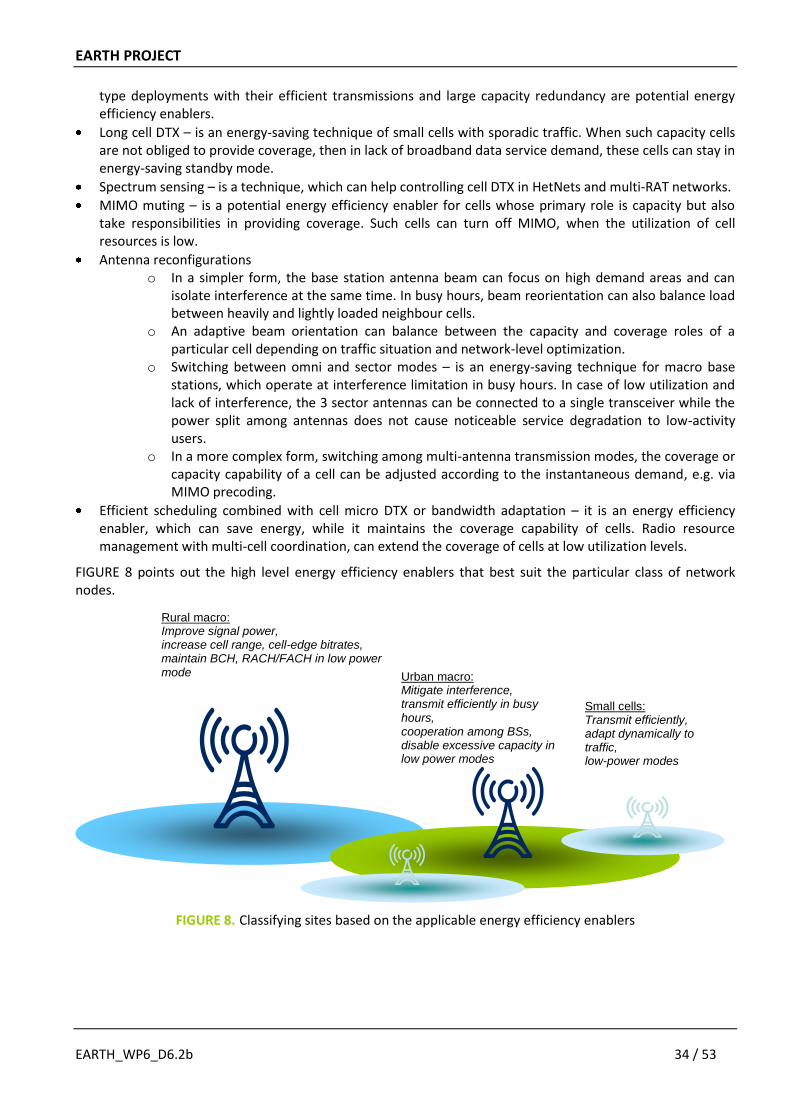
EARTH PROJECT
EARTH_WP6_D6.2b 34 / 53
type deployments with their efficient transmissions and large capacity redundancy are potential energy efficiency enablers.
Long cell DTX – is an energy-saving technique of small cells with sporadic traffic. When such capacity cells are not obliged to provide coverage, then in lack of broadband data service demand, these cells can stay in energy-saving standby mode.
Spectrum sensing – is a technique, which can help controlling cell DTX in HetNets and multi-RAT networks.
MIMO muting – is a potential energy efficiency enabler for cells whose primary role is capacity but also take responsibilities in providing coverage. Such cells can turn off MIMO, when the utilization of cell resources is low.
Antenna reconfigurations o In a simpler form, the base station antenna beam can focus on high demand areas and can
isolate interference at the same time. In busy hours, beam reorientation can also balance load between heavily and lightly loaded neighbour cells.
o An adaptive beam orientation can balance between the capacity and coverage roles of a particular cell depending on traffic situation and network-level optimization.
o Switching between omni and sector modes – is an energy-saving technique for macro base stations, which operate at interference limitation in busy hours. In case of low utilization and lack of interference, the 3 sector antennas can be connected to a single transceiver while the power split among antennas does not cause noticeable service degradation to low-activity users.
o In a more complex form, switching among multi-antenna transmission modes, the coverage or capacity capability of a cell can be adjusted according to the instantaneous demand, e.g. via MIMO precoding.
Efficient scheduling combined with cell micro DTX or bandwidth adaptation – it is an energy efficiency enabler, which can save energy, while it maintains the coverage capability of cells. Radio resource management with multi-cell coordination, can extend the coverage of cells at low utilization levels.
FIGURE 8 points out the high level energy efficiency enablers that best suit the particular class of network nodes.
FIGURE 8. Classifying sites based on the applicable energy efficiency enablers
Rural macro: Improve signal power, increase cell range, cell-edge bitrates, maintain BCH, RACH/FACH in low power mode Urban macro:
Mitigate interference, transmit efficiently in busy hours, cooperation among BSs, disable excessive capacity in low power modes
Small cells: Transmit efficiently, adapt dynamically to traffic, low-power modes
EARTH PROJECT
EARTH_WP6_D6.2b 35 / 53
4.3. COMMON MANAGEMENT OF ENERGY EFFICIENCY ENABLERS
While different types of nodes can apply energy efficiency enablers individually, the optimisation of nodes and networks to temporal changes requires a reconfigurability and a management on short and longer timescales (see Section 2.2.1). The energy-saving features of various nodes can be switched on and off based on the historical daily statistics or instantaneous measurements. The first method suits radio nodes where user occurrences and behaviour are predictable, but its disadvantage is that an instantaneous traffic demand may not be served by the optimal network configuration. The second method based on instantaneous observations can adapt to sudden changes in traffic demand, but it is a more complex, closed-loop solution.
From the aspect of network management, the energy efficiency enablers can be under
autonomous control, where the cell itself can decide about activation and deactivation, e.g. cell micro DTX, MIMO mode switching are such techniques;
coordination in the neighbourhood of cells, e.g. bandwidth adaptation and ICIC;
central control, e.g. in case of macro-cell and antenna-system reconfigurations.
The following list contains the potential cell measurements that can be used in the decision on activation/deactivation of energy-efficiency enablers:
Tracking area update events – estimate the number of inactive users in the area. Compare recent measurements to the historical daily profile statistics.
Handover events – short and long-term statistics collected separately for the different neighbours.
Radio link failure events.
Number of active users (e.g. with active data channels or with non-empty data buffer) – short and long-time averages.
Utilization (resource block utilization in LTE) – short and long-time averages.
Channel feedback, i.e. CQI, PMI and RI.
Interference levels of sub-bands.
Cell throughput – short and long-time averages.
Mobility measurements reported at handovers, after radio link failures or periodically.
MAC-layer latency – the schedulers monitor serving delays of those user buffers, which cannot be scheduled for some reason.
MAC-layer serving rates – the schedulers monitor the lengths of user buffers, and can take serving rate measurements of non-empty buffers. These measurements can indicate if a slow-down of service rates occur in a cell, and that correlates to the user-perceived service performance.
Different measurements can be used for different transitions, in the following we will briefly identify possible measurements that the transitions between configurations for the different application scenarios could be based on:
Transition from high to low traffic intensity in rural areas
When the average resource utilization and active user count decline in certain periods of days, energy-saving features are activated. Some of these features can be switched on/off instantaneously, and switching some other features involves more cells and coordination with network management. In case of rural area, some cells can go into standby mode and the remaining cells can compensate them coverage-wise. Tilt adjustment, beamforming on the antenna system or bandwidth reduction in the transceiver can increase the coverage range of compensating cells. Independently from these, cell micro DTX can further decrease the power consumption of coverage-providing cells.
Transition from low to high traffic intensity in rural areas
The first sign of rising traffic demand is the increased resource utilization and active user count in the coverage-providing cells. By also checking the MAC-layer service rates, the cell itself or the network
EARTH PROJECT
EARTH_WP6_D6.2b 36 / 53
management can decide if immediate action is needed or not. First the deactivation of DTX mode or a step increase in bandwidth, then turning on additional cells can assure that the service quality always remain satisfactory in the area.
Transition from high to low traffic intensity in urban areas
Urban areas dispose of high amount of surplus network resources in parts of the day. The underutilization periods are predictable in certain network nodes, therefore a strategy can be build on how and when to remove and reinstall network resources. The high-power cells are the most probable candidates of network-arranged energy-saving techniques, such as, reconfiguration of base station sectorization, bandwidth or antenna system.
In other situations, autonomous power-saving techniques based on instantaneous measurements can be applied. For example, spectrum sensing can drive the energy-saving features of low-power small cells. Cell micro DTX, due to the configuration ease can be applied dynamically on any radio node. The measurements to monitor are the same as described earlier. When the utilization and active user count in a cell are below threshold for a period of time, and the MAC layer service rates of users are safely above the target level, then network management may allow the cell to take energy-saving actions. Small, capacity cells safely overlapping with coverage-providing macro cells may take independent and immediate decisions about their low-power modes.
Transition from low to high traffic intensity in urban areas
Assume that only the coverage-providing macro cells are active in an area where user activity is intermittent. Even these cells can operate at a reduced-power mode, e.g. covering the 3 sectors of a base station only with a single radio. If traffic demand appears in the area, then the network attempts to serve the traffic from these coverage-providing macro base stations. In case only a few users are active and with relatively low-bandwidth services, then service by the macros might be sufficient. The MAC-layer user performance measurements might trigger warnings when the service quality becomes unacceptably for some users and then more radio resources should be turned on to serve the increased traffic demand. Multi-RAT, multi-frequency sensors might help the network to decide what particular cell should be activated in order to provide the best available service to users.
4.4. CLASSIFICATION OF EARTH ENERGY EFFICIENCY ENABLERS
The baseline reference system [9] consist of macro deployment which acts on the longest time scale, at medium time scale there is no management, while at the fastest time scale it provide standard RRM functionality. On top of this, as building blocks for the EARTH system or integrated concept, we can add the EARTH energy efficiency enablers. These are defined from the selected most promising tracks (see chapter 3). FIGURE 9 summarizes the EARTH energy efficiency enablers sorted according to application areas, according to deployment scenarios (y-axis), optimization timescales (x-axis), and traffic load (colour). Since the enablers are defined per time scale of operation, at a first glance it can be interpreted as the same solution is mentioned several times. However, when we say deployment of a solution that relates to the long time scale (once deployed, then it is there), while management of the same solution relates to (re)configurations of it acting on a shorter time scale, as was further discussed in Section 2.2.1.1.
Note that the boxes in FIGURE 9 not represent a configuration of EE enablers that play well together, but rather is a mapping of each enabler to the application scenario where it is believed to be most beneficial.
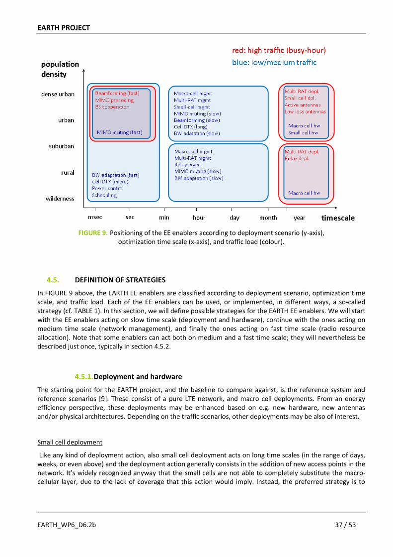
EARTH PROJECT
EARTH_WP6_D6.2b 37 / 53
FIGURE 9. Positioning of the EE enablers according to deployment scenario (y-axis), optimization time scale (x-axis), and traffic load (colour).
4.5. DEFINITION OF STRATEGIES
In FIGURE 9 above, the EARTH EE enablers are classified according to deployment scenario, optimization time scale, and traffic load. Each of the EE enablers can be used, or implemented, in different ways, a so-called strategy (cf. TABLE 1). In this section, we will define possible strategies for the EARTH EE enablers. We will start with the EE enablers acting on slow time scale (deployment and hardware), continue with the ones acting on medium time scale (network management), and finally the ones acting on fast time scale (radio resource allocation). Note that some enablers can act both on medium and a fast time scale; they will nevertheless be described just once, typically in section 4.5.2.
4.5.1. Deployment and hardware
The starting point for the EARTH project, and the baseline to compare against, is the reference system and reference scenarios [9]. These consist of a pure LTE network, and macro cell deployments. From an energy efficiency perspective, these deployments may be enhanced based on e.g. new hardware, new antennas and/or physical architectures. Depending on the traffic scenarios, other deployments may be also of interest.
Small cell deployment
Like any kind of deployment action, also small cell deployment acts on long time scales (in the range of days, weeks, or even above) and the deployment action generally consists in the addition of new access points in the network. It’s widely recognized anyway that the small cells are not able to completely substitute the macro-cellular layer, due to the lack of coverage that this action would imply. Instead, the preferred strategy is to
EARTH PROJECT
EARTH_WP6_D6.2b 38 / 53
deploy small cells alongside macro cells in the network, and the following strategies could be identified as the most straightforward for the small cells deployment:
sporadic addition of small cells to close coverage holes (coverage use case)
addition to increase capacity of an existing deployment (capacity use case)
For both the approaches listed above a proper trade off of coverage and capacity goals with the energy consumed by the added small cells has to be taken into account, and has been the main purpose of the activity performed in EARTH in this context. As intuitively clear, setting up additional small cells, besides adding energy consumers, generally changes network characteristics. Fair evaluation of energy consumption (or efficiency) of different deployments then requires an evaluation of networks at the same “operating point”, which includes notions of coverage, overall throughput, and cell edge user performance. For instance adding some pico cells to an existing macro deployment may increase coverage from 95% to 99% with respect to some given area and inevitably increases the networks overall energy consumption.
A meaningful evaluation must not compare the same network with and without the additional pico cells since both provide different coverage values. Much rather should one compare the pico cell deployment to another network extension providing (almost) the same coverage, e.g., one featuring increasingly directive antennas. As mentioned above, similar considerations apply with regard to other KPIs such as the network’s throughput or cell edge user performance.
From a merely theoretical point of view it could be interesting to evaluate what happens in a use case where small cells may be deployed only to reduce the overall energy consumption of a network and without increasing coverage or throughput (note here, that throughput denotes the amount of actually transported data, which is upper bounded by the traffic demand. Naturally, network capacity is always increased by adding access points). The main effect being exploited in this case is that traffic is drawn away from macro cells and served by small cells. The additional small cell power is over compensated by a reduction in consumed power at the macro cells. The energy reduction achievable in this way, however, depends strongly on the degree of localization of the traffic demand. In other words, the more traffic can be captured by small cells, the larger the power reduction at the macro BSs.
Relay deployment
Energy efficiency of a macro-only system can be improved by a correct relay nodes deployment for serving additional capacity and/or coverage needs. Nevertheless gains strongly depends on several factors, and the following considerations should be made when evaluating this particular deployment option: first of all, the additional capacity provided by the relay is generally also accompanied by an additional power consumption, and an incorrect placement of the relay node in the coverage area could reduce the overall EE gain. When used for capacity, traffic distribution is crucial in order to exploit the presence of relay nodes, which preferably should be placed in correspondence of hotspots. Type 1 relays (2-hop scheme) are more energy efficient than other kinds of relays using multicast cooperative techniques (potential Type 2, not standardized yet).
Relay Nodes, as defined in LTE-Advanced, are suited in scenarios with high traffic, especially hot spots, and in general when additional capacity is needed w.r.t. macro only scenarios. Performance evaluations, focused on interference limited scenarios, showed a strong impact of the power model of both the donor eNB (DeNB) and RN, and two hop scheme provide a gain w.r.t. the direct transmission, especially in high traffic situations. This suggests an indication about the timeframe for a possible introduction of Relay Nodes in a LTE-Advanced network, where efficient radio nodes and huge capacity demand will motivate the introduction of this particular kind of small nodes in areas where availability of wired backhaul is limited. In particular, the consideration of a delay in deployment of the relay nodes can be more beneficial, especially in case of considering the possibility to deploy RN and jointly upgrade the DeNB (an evolved donor eNB with extremely low power consumption may give additional benefits also to the relay deployment).
EARTH PROJECT
EARTH_WP6_D6.2b 39 / 53
However, as indicated before relay nodes can also be used as a tool to extend the coverage and more in general in scenarios where fiber is not available. Especially suitable for this are relay nodes with the capability of adapting to the instantaneous channel state by employing a hybrid forwarding scheme which can provide significant throughput improvement with small extra energy consumption, thus enhance the overall system energy efficiency in terms of Joule/bit. The most suitable scenario for that kind of relays is rural area where the inter-cell distance is large. However, the improvement can only be achieved given the following conditions:
The RNs’ position must be wisely chosen. System level results indicate that RNs should be deployed at the cell edge to achieve better energy efficiency.
The number of RNs deployed in each section is also a key issue. Deploying too many RNs in one sector will only result in negligible throughput enhancement but considerable extra energy expenditure, leading to lower energy efficiency. Based on the current Macro cell and relay power models, no more than 6 hybrid relay nodes should be deployed in each sector.
The cooperation manner of RNs within each sector plays an important role. Relay selection and relay CoMP are two potential candidates.
Generally speaking, relay technique can be accommodated with most of other energy saving technologies as long as coupling network management and radio resource management algorithms are considered.
Multi-RAT deployment
From a practical perspective, it is a fact that most network operators already have live network deployments in place, using legacy RATs (Radio Access Technology), practically 2G GSM and its successors, as well as 3G WCDMA and more advanced versions (HSPA). Consequently it is foreseen that pure LTE “green field” deployments are less likely to occur. Another aspect to be taken into account is the penetration of LTE capable devices among customers. Again, 100% LTE device penetration is not likely to be reached at the beginning of LTE service, hence in order to pertain service of legacy UEs, LTE only deployment without considering former network is not always realistic. The following strategic considerations focus on data services, hence GSM is assumed to be not involved in the description and assumed to be kept by the operators mainly for voice services. Deployment is motivated by the steady rise in data traffic demands. This is caused by the introduction of new LTE service as well as the rise of traffic over the legacy system. It is realistic to consider that new, LTE capable devices gradually also take over traffic from legacy networks (as customers changing their devices). The focus of the strategy should be on replacing legacy equipment with more power efficient, more compact equipment, which is capable to integrate modules of legacy and new RATs in single housing. Such base stations keep up with the increasing traffic demand and changing traffic mixes, while fit the existing infrastructure and lease contracts that had been originally dimensioned to the legacy network.
According to these considerations, when market is ready for LTE deployment the energy-aware multi-RAT upgrade strategy follows:
Use the legacy sites, upgrade backbone network where needed
Replace old legacy equipment with multi-RAT capable base stations, because
o It saves energy, see the co-siting gain calculations in [19]
o No need for a major upgrade in site infrastructure
o Power supply, room of cabinets, cooling capacity, rooftop (multi-band antennas), hence the leasing costs of sites can remain the same as dimensioned for the legacy network alone
o Modular base stations provide flexibility in setting the traffic mix between legacy and LTE networks
o Site upgrade options remain open
EARTH PROJECT
EARTH_WP6_D6.2b 40 / 53
o Better EE adaptation features at node level
o Better functionalities for EE management
o Option for smooth and gradual phase out of legacy nodes
Refarm part of the lower band of GSM for LTE in order to serve mobile broadband from rural multi-RAT sites.
Note that real multi-RAT deployments are also limited by network policies, marketing requirements and strategies as well as possible regulatory constraints, etc. In particular, the following constraints should be taken into account:
The availability or refarming of frequency bands can be limited.
Universal voice service should be provided everywhere that is limiting the reduction or replacement of legacy networks (c.f. CS fallback is proposed until not “all” terminals can handle PS voice calls).
Electromagnetic exposure regulations must be kept.
Furthermore, in a typical network upgrade situation, the existing legacy macro sites are not sufficient for a fully-built high-band LTE network, thus additional sites with macro base stations or small cells are needed (see previous sections).
Active antennas
Active antennas are considered an important EE enabler since they represent a step forward with respect to the case of RRHs, that usually are placed on top of masts, close to antennas and are connected to the BS at the base of the mast through optical fibres enabling significant reduction in the losses along the TX/RX chain. In this direction, the next step includes Active Antennas (AAS) where signal conversion stages, filtering, active RF parts and the radiating elements become integrated into a new device fed by optical fibres, allowing reducing further the losses.
As well as losses reduction, with AAS, DL power needs are reduced and a better sensitivity of the BS reception chain can be achieved.
But, primarily, AAS are a straightforward means to apply beamforming (or MIMO) techniques, either in slow or fast versions, enabling a reduction of interference and a drop in power requirements either in UL and DL.
Even without any kind of applied beamforming techniques, anyway, AAS proved to be beneficial in terms of energy efficiency and in particular, as a result of the simulations described as an example in [22], for the macrocellular case of the dense urban scenario. Moreover it is deemed as relevant also the scenario of AAS applied to macrocells deployed in a HetNet environment, to achieve a proper integration between the macro and the micro/pico layer.
Low loss antennas
The low loss antennas developed in EARTH can provide about 15% improvement over a commonly used solution for printed arrays. The obvious strategy is to use EARTH low loss antennas wherever a printed antenna is used (an estimate is 30% of the antennas in a country-wide network [22], typically in urban areas/sites).
EARTH PROJECT
EARTH_WP6_D6.2b 41 / 53
Macro cell hardware
The macro cell hardware developed in EARTH will provide basis for future macro base stations with significant power savings. The hardware supports features that allow it to be operated according to three different strategies:
Operating point adjustment, which allows the transceiver to adapt the operating point (and thereby the efficiency) to be optimal for different output power levels. As such, this strategy is an enabler for efficient bandwidth adaptation.
Component deactivation, which allows the transceiver to enter sleep modes on a fast time scale, hence being an enabler for efficient cell DTX.
A combination of operating point adjustment and component deactivation.
Small cell hardware
The small cell hardware developed in EARTH will provide basis for future small base stations similar to the macro cell hardware for macro base stations. This hardware supports also features to provide significant power savings operating according to three different strategies:
Operating point adjustment, which provides different output power levels adjusting the operating point to the most energy efficient one. This strategy could be an enabler for efficient bandwidth adaptation.
Component deactivation, which deactivates some components to implement sleep modes to save energy following LTE signals. This strategy is a fast time scale one, hence being an enabler for efficient cell DTX.
A combination of two previous strategies: operating point adjustment and component deactivation.
4.5.2. Network management
In the EARTH baseline system [9], no management actions are implemented. Hence, there are several possibilities to save energy by managing the macro-cell deployment. Also when other deployments are introduced to handle traffic, it is important that these are managed in an energy efficient manner.
Macro cell management
The anchor points of mobile networks are the macro sites, which typically have good infrastructure support, e.g. tower or rooftop antennas, heavy-duty protected power supply and high-speed backhaul connection. A large part of the OPEX, especially the energy costs, are proportional to the number of macro sites, so operators intend to reuse their sites in network upgrades either by extending the capacity of existing sites or by supporting newly established sites from existing sites (e.g. as donor cells for relays, hubs for remote radio heads or hubs for backhaul connections).
Radio resources concentrated at macro sites often exceed the peak-hour needs of the served area, so a common management of site resources can exploit the energy saving potential by unifying the traffic of individually underutilized cells. A macro site itself collects information on local traffic, attached users, channel conditions, service quality and resource utilization, so, potentially, the site can make local network management decisions as well.
Macro-cell management actions in a given service area are governed by the service quality and load situation. By observing the daily patterns of network utilization and service quality a daily schedule of network reconfigurations can be established. For example, the reconfigurations of antennas, operational bandwidth or cell DTX can directly change the focus of network coverage for the different periods of days, while the reconfiguration of mobility parameters or scheduling priorities can indirectly influence service priorities via

EARTH PROJECT
EARTH_WP6_D6.2b 42 / 53
adjusting RRM operations. Thus the management actions that are part of macro cell management are the following:
Dynamic sectorization suits well macro base stations which operate at interference limitation in busy hours. When traffic and, consequently, interference are low, coverage can be maintained with fewer sectors, e.g. with an omnidirectional macro sector without jeopardizing service quality. The EE enabler slow beamforming (see below) can be utilized to accomplish this.
Antenna reconfigurations, such as tilt, beamwidth and direction adjustments, can be coupled with scheduled switching of neighbour macro or nearby small base stations. Alternatively, antenna reconfigurations can depend on known daily pattern of base station load or can be driven by known hot spot activity. See also slow beamforming below.
Power and bandwidth adaptation (see below) do not degrade coverage, while have high potentials to save significant amount of energy in lightly loaded cells. Power adaptation is slightly different in the sense that it is applicable to interference limited cells in a similar manner as dynamic sector switching.
Long cell DTX (see below) is applicable to macro cells, which do not have coverage duties in the network, i.e. the remaining active cells at the same or different sites provide overlapping coverage.
Macro cell functionalities may include the control and supervision of satellite sites (e.g. indoor and micro cells, relays, remote radio units) and the localization of users by sensors.
Some of the EE enablers associated with macro cells assume that macro cells are authorized to control site-related mobility parameters, so that the network can force horizontal and/or vertical handovers before radio resources are switched into sleep mode.
Macro cell management is responsible to set target and threshold levels for various RRM algorithms that control the operation of network nodes on short timescales. For example, scheduling priorities, MIMO and carrier switching.
These can be combined in several different ways, resulting in numerous macro cell management strategies.
Small cell management
Small cells are typically deployed where extra capacity and/or improved radio links are required. With some exception, such as the indoor cells, small cells are not essential for coverage. It is expected that the deployment of macro sites will stop at a certain level of density and an increasing part of traffic will be served by small cells in urban areas. Despite small cells consume a fraction of the power of macro cells, small cells will appear in great numbers and their power consumption will be comparable to that of the macro layer of cells in urban networks [8].
The service radii of small cells are in the order of a couple hundred meters maximum, but rather less, since they are intended to serve hot spots from street level with antennas, which are directed such that they should not interfere with the macro layer. We can still assume that the coverage area of outdoor small cells will overlap with the coverage of macro layer, hence in lack of users, this dual coverage is redundant. Due to the small service area of micro and pico cells, the occurrences of active users can be widely variable from very heavy load to long idle periods. Therefore the usage pattern of small cells suits well energy efficiency enablers, which fully deactivate these cells when traffic demand is not present.
Hence all forms of cell DTX, including switching on long and short timescales, are recommended to small cells. Activation of small cells can be fully on demand, for example driven by sensors, which detect user traffic towards macro cells. Or activation can be governed by macro cell load, such that the macro cell localizes the user and its traffic behaviour, and the macro cell may turn the nearby small cell on, then the user is handed over to it. The activation trigger can be also a combination of the two mechanisms, localization is done by the small cell, but the actual decision is done by the macro cell.
EARTH PROJECT
EARTH_WP6_D6.2b 43 / 53
The load pattern of small cells can be fully predictable in some cases, so that the busy and idle periods of usage are known. In such situation, the central network management can schedule the activation and deactivation of cells.
The daily traffic variation of individual small cells can exceed many more times that of the network level, so the energy-saving potential in the small-cell layer directly depends on the human mobility patterns, which is strongly site-specific.
Relay management
Energy efficiency gains of a relay system depends on how relays are managed mainly because the additional capacity provided by these low power nodes in general is not fully exploited during all the daily operation. In particular, during the night (when the average traffic demand is lower), additional benefits are possible when some on-board sleep mode mechanisms are considered in the hardware of the relays, e.g. triggered by a proper MBSFN switching mechanism in the packet scheduler of the RN and/or in the link scheduler of the DeNB (macro node).
Moreover, since the usage of MBSFN subframes is native in normal Relay Nodes operation (half duplex), the usage of MBSFN switching mechanisms in Relay Nodes is seen as an important enabler for the deployment of Relay Nodes over a macro only scenario. Ultimately, this management technique could provide the additional needed capacity (hot spot of traffic) by using relays just when needed (sleep mode mechanisms are triggered during MBSFN subframes), in order to limit the overall power consumption in the network.
Multi-RAT management
Focused on saving energy in a Multi-RAT environment EARTH project provides new medium timescale opportunities by managing UEs connections to the most suitable RAT/BS in real time [10] [19]. This energy oriented policy is guided by energy efficiency metrics computed by BSs and used as criteria to trigger Handovers among different RATs (Vertical Handovers), or even among BSs of the same RATs (Horizontal Handover). Thus Vertical Handovers can be used as an opportunistic technique to connect UEs and corresponding services to the most suitable BS/RAT that in real time is considered the most energy efficient to transmit data of a given service. For example: the voice service transmission can be more energy efficient when transmitted by RATs that were designed to support circuit switched radio connections, however IP based services can be more efficiently transmitted in pure packet switched radio networks.
Additionally and since this technique also includes propagation issues, it can trigger handovers to BSs that, from the radio link viewpoint, are the ones that requires less power to transmit service associated data.
The previous concept can be combined with other techniques since decisions are made by a Multi-RAT entity in a multi seconds time scale, thus can work on top of ms time scale RRM techniques.
This technique can also be interesting to use before shutdown of a given BS, e.g., if a BS serves a reduced number of users, then one can start to perform handovers, preparing the BS to shutdown.
Beamforming (slow)
Slow beamforming is an enabler for network management strategies aiming for energy efficient mobile radio networks by in an adaptive manner map communication resources to where these are needed in space. The word slow is used to point out that antenna parameters are adapted to average conditions in the network taking all users in the system into consideration in contrast to fast beamforming where antenna patterns typically are adapted on a per user basis on a very short time frame. Examples of system conditions that can adapted to are changes in traffic intensity (high/low), non-uniform spatial location of traffic demand
EARTH PROJECT
EARTH_WP6_D6.2b 44 / 53
(clustering), non-stationary location of traffic demand (clusters moving). In the case of hotspots antenna parameters are adapted for maximal throughput which typically means that offered traffic is shared between cells as antennas are pointed towards hotspots. Another strategy for which antenna reconfiguration is an enabler is cell reconfiguration, for example changing the number of cells at a site. Antenna parameters in active cells can then be adapted such that the system retains coverage and support the traffic demand in an energy efficient manner.
Antenna parameters considered for adaptations are in addition to the well accepted antenna tilt also beampointing direction and beamwidth in azimuth.
The scenario in which reconfigurable antenna systems is likely to offer most significant gains are large variations in average load and where the traffic is spatially clustered and with cluster positions moving over time. The reconfigurable antennas are most likely deployed on macro sites, possibly in a heterogeneous network, and are as such an obvious tool in macro cell management.
Cell DTX
Discontinuous transmission (DTX) has for a long time been used in mobile terminals to achieve long battery life. The idea is to only transmit when there is a need, and otherwise put the transmitter in a low power state. At the network side this technique is referred to as cell DTX, and as such it builds on the macro and small cell hardware strategies (see above) on component de-activation which facilitates low power states. At a high level we can distinguish between two cell DTX versions: Fast cell DTX and long cell DTX.
Fast cell DTX acts on slot/subframe level and exist in some different versions as well. Cell micro DTX is possible already in LTE Rel-8 and means that the radio is put into DTX between the CRS transmissions. In the next version which is referred to as MBSFN-based DTX MBSFN subframes are used to make room for longer sleep periods since no CRS are transmitted in these subframes. This is also in principle possible in LTE Rel-8, but a faster MBSFN reconfiguration would be needed to make it better. Finally, we have cell short DTX, in which the CRS are assumed to been removed and replaced by DMRS hence leaving room for even longer sleep periods. This is not possible in the LTE standard today, but may be so in the future. All these fast cell DTX versions are most effective in low load scenarios, but there is no drawback at high load either. At least three different strategies can be identified:
Implement cell DTX alone.
Implement cell DTX combined with power control (see Scheduling below). In that way cell DTX provides savings at low load, while power control provides energy savings at high load.
Implement cell DTX combined with bandwidth adaptation. This has potential of significant energy savings since saving potentials are exploited in both the time and frequency dimensions.
Long cell DTX acts on a slower time scale, and in principle it can be seen as the cell is put into a low-activity mode [11]. As such is can be seen as a cell sleep, and in principle it could be based on a deeper sleep state (lower power consumption) than the low power state considered above for the fast cell DTX versions. However, currently in the EARTH macro and small cell hardware only one low power state is envisioned. One use case or strategy for long cell DTX is in relatively densely deployed networks where the coverage is good (dense urban, urban, suburban). Then capacity nodes can be put in long cell DTX during low-traffic periods. Hence long cell DTX can be seen as an enabler/tool for many network management actions such as small cell management and multi-RAT management, but also macro cell management.
Further information on cell DTX can be found in [11] and [22].
EARTH PROJECT
EARTH_WP6_D6.2b 45 / 53
Bandwidth adaptation
In early investigations we observed that there is a strict correlation between traffic load profile and scheduler strategy with regard to energy consumption. We have introduced the BW adaptation as a scheduling strategy which is based on adjustment of the bandwidth to the required traffic load. During medium or low traffic where fewer users are active or less data is transmitted the bandwidth is stepwise downscaled, and so lower number of resource blocks (PRBs) is allocated. In opposite case, when number of users or the amount of transmitted data increase, the bandwidth is expanded.
Bandwidth adaptation is based on the power amplifier’s operating point adjustment functionality of macro and small cell BS hardware. The required bandwidth can be calculated for each bandwidth usage between 1.4 MHz and upper bandwidth of a base station and is determined by sophisticated algorithms considering number of active users, transmitted data, base station capacity, operator policies or other parameters.
The BW adaptation can be applied for different time scales. By reconfiguration of the BS system parameters the technique acts on slow and medium time scale as a network management action. In contrast, usage of carrier aggregation (CA) procedure is an approach on the fast time scale. The required CA procedure is currently not standardised by 3GPP and needs specification of a fast stepwise switching, e.g. between the lowest BW usage at 1.4 MHz and up to the highest BW usage at 10 MHz. The other solution using a reconfiguration of cell parameters is very slow and may impact the performance of cell-edge users.
An alterative implementation of the strategy, that is backwards compatible to LTE, is Capacity Adaptation (CAP). This method does not change the maximum used bandwidth and the number of reference signals. An adaptation to lower load is performed by modifying the scheduling strategy, i.e. limiting the number of scheduled PRBs per subframe. Similar to bandwidth adaptation, this approach allows lowering the PA supply voltage, but it is transparent to the UEs and maintains frequency diversity.
Especially in suburban and rural areas, it is in times with medium or low traffic the bandwidth adaptation promises high energy savings. Furthermore, combination with other scheduling methods, for example utilizing cell DTX, can provide further savings.
MIMO muting
The main idea behind MIMO muting, or antenna muting, is to activate and de-activate antennas based on the traffic demand; if a single antenna can mute the traffic, then mute the other antennas. Since each antenna typically is served by a separate PA, this can save significant amounts of energy [22], and then especially in low load situations.
Antenna muting may operate on different time scales, and consequently there are two high level strategies on how to use antenna muting:
Fast antenna muting. In this case the activation and de-activation of antennas operate virtually on a packet-by-packet basis, or in the order of a few tens of milliseconds. The activation and de-activation of antennas can be based on e.g. resource utilization, amount of data in buffers, or some QoS measure. It is proposed to apply this strategy in relatively densely deployed networks where the coverage is good (i.e. dense urban, urban and suburban). Given that, the strategy will have no impact on coverage and network capacity, but user data rates may be somewhat reduced at low load. Further information and results can be found in [22].
Slow antenna muting. In this case the activation and de-activation is done in a sense that it follows average traffic statistics, e.g. during the day. With this strategy there is a large risk of degraded user data rates, since instantaneous traffic is varying faster than the average traffic statistics.
EARTH PROJECT
EARTH_WP6_D6.2b 46 / 53
4.5.3. Radio resource allocation
Since traffic changes are varying at a fast scale, it can be expected that significant energy savings can be expected by adapting the available radio resources to these traffic changes. Note that some techniques acting on medium time scale, also can act on fast time scale, e.g. cell DTX, bandwidth adaptation, and MIMO muting (see section 4.5.2).
Beamforming (fast)
The fast beamforming algorithms allow to concentrate the DL radiated power on a per-user basis and to select the received signal from each user in UL, so both UL and DL interference should be reduced and the overall UL (at UE level) and DL (at BS level) power requirements dropped .The beamforming procedures, applied either on a per-cell or on a per-user basis, could generally imply a reduction in the overall radiated power.
These types of algorithms are very well suited to active antennas, where they can be applied remotely, ensuring also a significant saving in terms of capacity to be transmitted over the fiber link. In such a case, as demonstrated in the works reported in [22], there exist a superimposition of the benefits due to the beamforming algorithm with the advantages in terms of energy efficiency due to active antennas.
Even if the fast beamforming has been proved to be beneficial for suburban or rural scenarios in literature works, in EARTH simulations results lead to consider it useful also in urban macro scenarios, both in term of spectral efficiency and of energy savings.
Due to the need of antenna arrays and considering frequencies used in LTE fast beamforming algorithms are mostly used for macro-cellular scenarios.
Finally fast beamforming, in particular in conjunction with active antennas deployment, are an enabler of future collaborative multi-node architectures.
MIMO precoding
MIMO precoding is an inherent part of the LTE standard, and in EARTH a MU-MIMO precoder tailored to the properties of the PA is developed, allowing to reduce the output power of the PA by approximately 1 dB and with only a very small degradation in spectral efficiency [22]. The proposed strategy is to use this precoder when MU-MIMO is considered.
BS cooperation
BS cooperation has been identified as one of the major development paths for increased traffic demand. BS cooperation requires additional backhaul links and more complicated processing algorithms, leading to more energy consumption. However, the cell throughput can be significantly improved as well as the EE performance of the system.
There are two different strategies for BS to cooperate: firstly, the BSs can jointly transmit and receive from the UEs in order to exploit the interference; secondly, the BSs can coordinate the used frequencies and eliminating the interference.
For the first BS cooperation strategy, improved EE can be achieved in dense urban scenario with small ISD. However, no more than three BSs should be used for cooperation when practical power model is taken into account. In the second strategy, frequency bandwidth is dynamically allocated to BSs with unbalanced traffic load. An EE gain in the order from 8% to 15% can be achieved. Furthermore, it must be coupled with multi-cell scheduling.
EARTH PROJECT
EARTH_WP6_D6.2b 47 / 53
BS cooperation is most suitable for macro deployment and is likely to provide gains in highly loaded scenario. It can be seen as an enabler when coupled with fast beamforming with active antennas.
Power control
Power control adjusts the transmit power per resource element according to e.g. (traffic) load and channel quality. The target is to fulfil the QoS requirements with as low output power as possible. Power control has been found suitable for high load scenarios, but in combination with cell DTX (see above) it creates a very attractive overall scheduling solution (see below).
Scheduling
Scheduling is concerned with maximizing outcome at a fixed power cost using a set of levers that include transmit power, radio channels, transmission delay, modulation or coding. Most existing RRM strategies and algorithms are designed around the full load or peak traffic assumption. They apply when large numbers of terminals are competing for high data rates. In fact, some techniques specifically address situations in which the capacity requirement is higher than the available capacity (overload). While these techniques can still be applied, in low load they carry little benefit in this setting and do not address power consumption. In contrast, an RRM strategy that is sub-optimal or spectrally inefficient at high loads may be able to fulfill capacity targets at much higher EE. In this section, green RRM is approached from three points of view:
In the first strategy, the dynamics in scheduling are exploited by putting the BS in sleep mode by utilizing MBSFN subframes, of which the data region doesn’t contain common RS, as explained in the cell DTX section above. The main idea here is to dynamically (or semi-statically) configure the MBSFN subframes ratio and positions according to channel and traffic conditions. As a general principle, the more traffic, the lesser is the ratio of MBSFN subframes whereas we utilize more MBSFN subframes without data/control signaling in lightly loaded scenarios.
In the second strategy, algorithms utilizing adaptive DTX and power control are proposed; by studying techniques such as using sleep modes or reducing transmit power or combinations of both. The proposed technique can have a gain of as much as 30% especially in very low load scenarios. The innovation is here that sleep modes and power control are not two exclusive techniques but should rather be exploited jointly.
In the third strategy, the delay characteristics of a specific application can be exploited in order to reduce the transmit power, resulting in a tradeoff between spectral efficiency and energy efficiency, especially in lightly loaded scenarios. In particular, such a technique increases the delay experienced by the application, but this is acceptable as long as it is within the delay constraints of the QoS requirements. This approach can bring about gains from anywhere from 0-20% depending on the traffic load in the system.
4.6. IDENTIFICATION OF PROMISING CONFIGURATIONS
Based on the strategies defined in section 4.5 above and on results achieved in the project [19][22], we will in this section identify promising configurations. A configuration is a collection of strategies, with at least one strategy per time scale. A configuration is commonly chosen with respect to a certain application scenario.
Note that the configurations listed here do not exclude identification of further promising configurations, but these are promising ones identified so far with the aim of providing as much energy savings as possible and with minimal impact on the baseline system [9].
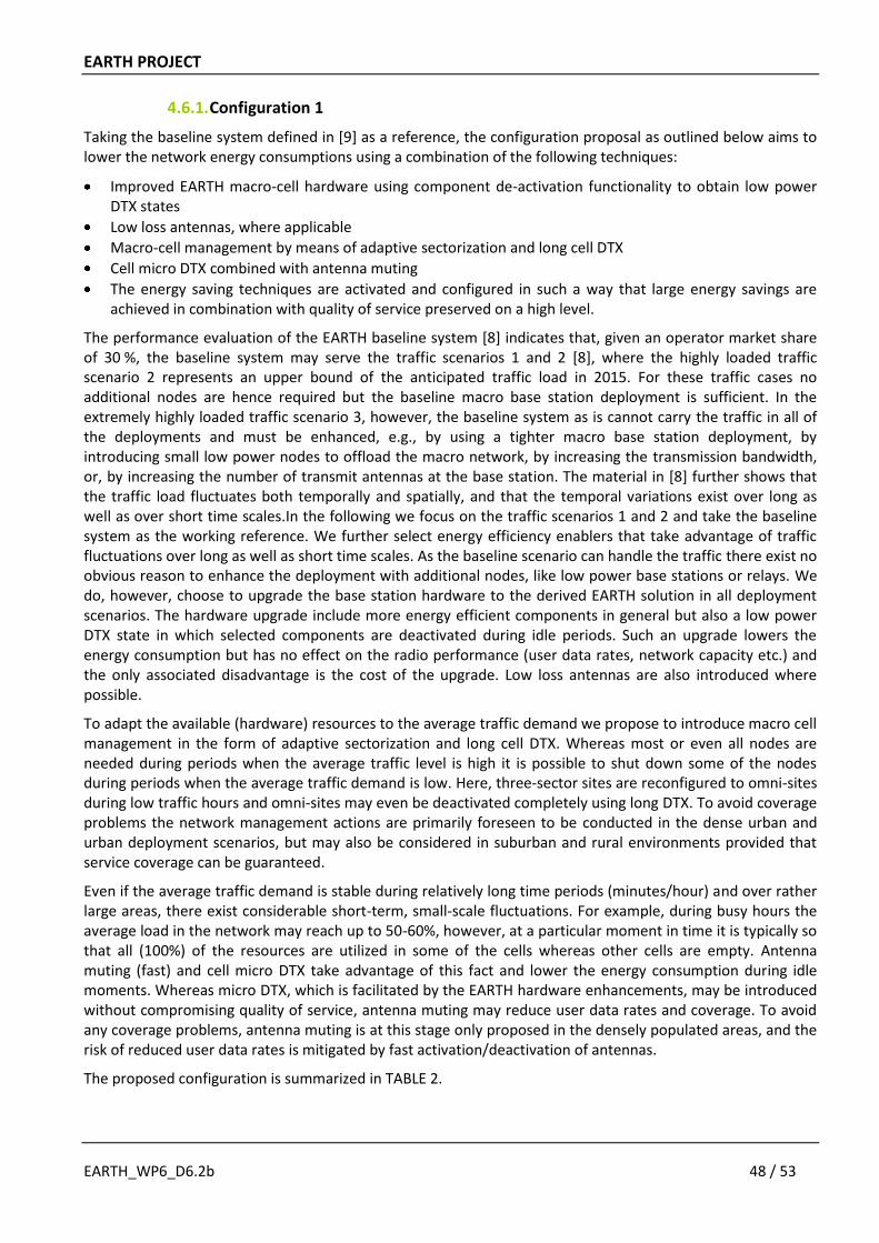
EARTH PROJECT
EARTH_WP6_D6.2b 48 / 53
4.6.1. Configuration 1
Taking the baseline system defined in [9] as a reference, the configuration proposal as outlined below aims to lower the network energy consumptions using a combination of the following techniques:
Improved EARTH macro-cell hardware using component de-activation functionality to obtain low power DTX states
Low loss antennas, where applicable
Macro-cell management by means of adaptive sectorization and long cell DTX
Cell micro DTX combined with antenna muting
The energy saving techniques are activated and configured in such a way that large energy savings are achieved in combination with quality of service preserved on a high level.
The performance evaluation of the EARTH baseline system [8] indicates that, given an operator market share of 30 %, the baseline system may serve the traffic scenarios 1 and 2 [8], where the highly loaded traffic scenario 2 represents an upper bound of the anticipated traffic load in 2015. For these traffic cases no additional nodes are hence required but the baseline macro base station deployment is sufficient. In the extremely highly loaded traffic scenario 3, however, the baseline system as is cannot carry the traffic in all of the deployments and must be enhanced, e.g., by using a tighter macro base station deployment, by introducing small low power nodes to offload the macro network, by increasing the transmission bandwidth, or, by increasing the number of transmit antennas at the base station. The material in [8] further shows that the traffic load fluctuates both temporally and spatially, and that the temporal variations exist over long as well as over short time scales.In the following we focus on the traffic scenarios 1 and 2 and take the baseline system as the working reference. We further select energy efficiency enablers that take advantage of traffic fluctuations over long as well as short time scales. As the baseline scenario can handle the traffic there exist no obvious reason to enhance the deployment with additional nodes, like low power base stations or relays. We do, however, choose to upgrade the base station hardware to the derived EARTH solution in all deployment scenarios. The hardware upgrade include more energy efficient components in general but also a low power DTX state in which selected components are deactivated during idle periods. Such an upgrade lowers the energy consumption but has no effect on the radio performance (user data rates, network capacity etc.) and the only associated disadvantage is the cost of the upgrade. Low loss antennas are also introduced where possible.
To adapt the available (hardware) resources to the average traffic demand we propose to introduce macro cell management in the form of adaptive sectorization and long cell DTX. Whereas most or even all nodes are needed during periods when the average traffic level is high it is possible to shut down some of the nodes during periods when the average traffic demand is low. Here, three-sector sites are reconfigured to omni-sites during low traffic hours and omni-sites may even be deactivated completely using long DTX. To avoid coverage problems the network management actions are primarily foreseen to be conducted in the dense urban and urban deployment scenarios, but may also be considered in suburban and rural environments provided that service coverage can be guaranteed.
Even if the average traffic demand is stable during relatively long time periods (minutes/hour) and over rather large areas, there exist considerable short-term, small-scale fluctuations. For example, during busy hours the average load in the network may reach up to 50-60%, however, at a particular moment in time it is typically so that all (100%) of the resources are utilized in some of the cells whereas other cells are empty. Antenna muting (fast) and cell micro DTX take advantage of this fact and lower the energy consumption during idle moments. Whereas micro DTX, which is facilitated by the EARTH hardware enhancements, may be introduced without compromising quality of service, antenna muting may reduce user data rates and coverage. To avoid any coverage problems, antenna muting is at this stage only proposed in the densely populated areas, and the risk of reduced user data rates is mitigated by fast activation/deactivation of antennas.
The proposed configuration is summarized in TABLE 2.
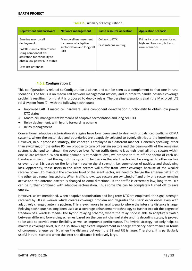
EARTH PROJECT
EARTH_WP6_D6.2b 49 / 53
TABLE 2. Summary of Configuration 1.
Deployment and hardware Network management Radio resource allocation Application scenario
Baseline macro-cell deployment
EARTH macro-cell hardware using component de-activation functionality to obtain low power DTX states
Low loss antennas
Macro-cell management by means of adaptive sectorization and long cell DTX
Cell micro DTX
Fast antenna muting
Primarily urban scenarios at high and low load, but also rural scenarios
4.6.2. Configuration 2
This configuration is related to Configuration 1 above, and can be seen as a complement to that one in rural scenarios. The focus is on macro cell network management actions, and in order to handle possible coverage problems resulting from that it is proposed to deploy relays. The baseline scenario is again the Macro cell LTE rel-8 system from [9], with the following techniques:
Improved EARTH macro cell hardware using component de-activation functionality to obtain low power DTX states
Macro-cell management by means of adaptive sectorization and long cell DTX
Relay deployment, with hybrid forwarding scheme
Relay management
Conventional adaptive sectorisation strategies have long been used to deal with unbalanced traffic in CDMA systems, where the sector size and boundaries are adaptively selected to evenly distribute the interferences. However, in our proposed strategy, this concept is employed in a different manner. Generally speaking, other than switching off the entire BS, we propose to turn off certain sectors and the beam-width of the remaining sectors is changed to maintain the coverage level. When traffic demand is at high level, all three sectors within one BS are activated. When traffic demand is at mediate level, we propose to turn off one sector of each BS. Handover is performed throughout the system. The users in the silent sector will be assigned to other sectors or even other BSs based on the long term receive signal strength, i.e. summation of pathloss and shadowing loss. Apparently, those users in the silent sectors will suffer from lower coverage because of the weaker receive power. To maintain the coverage level of the silent sector, we need to change the antenna pattern of the other two remaining sectors. When traffic is low, two sectors are switched off and only one sector remains active and the antenna pattern is changed to omni-directional. If the traffic is extremely low, long term DTX can be further combined with adaptive sectorisation. Thus some BSs can be completely turned off to save energy.
However, as we mentioned, when adaptive sectorisation and long term DTX are employed, the signal strength received by UEs is weaker which creates coverage problem and degrades the users’ experiences even with adaptively changed antenna pattern. This is even worse in rural scenario where the inter site distance is large. Relaying technique has long been used as a coverage enhancement technology to further exploit the degree of freedom of a wireless media. The hybrid relaying scheme, where the relay node is able to adaptively switch between different forwarding schemes based on the current channel state and its decoding status, is proved to be able to provide more flexibility as well as improved performance. The hybrid strategy not only helps to maintain coverage level, but it also shows significant improvement in energy efficiency performance in terms of consumed energy per bit when the distance between the BS and UE is large. Therefore, it is particularly useful in rural scenario when the inter site distance is relatively large.
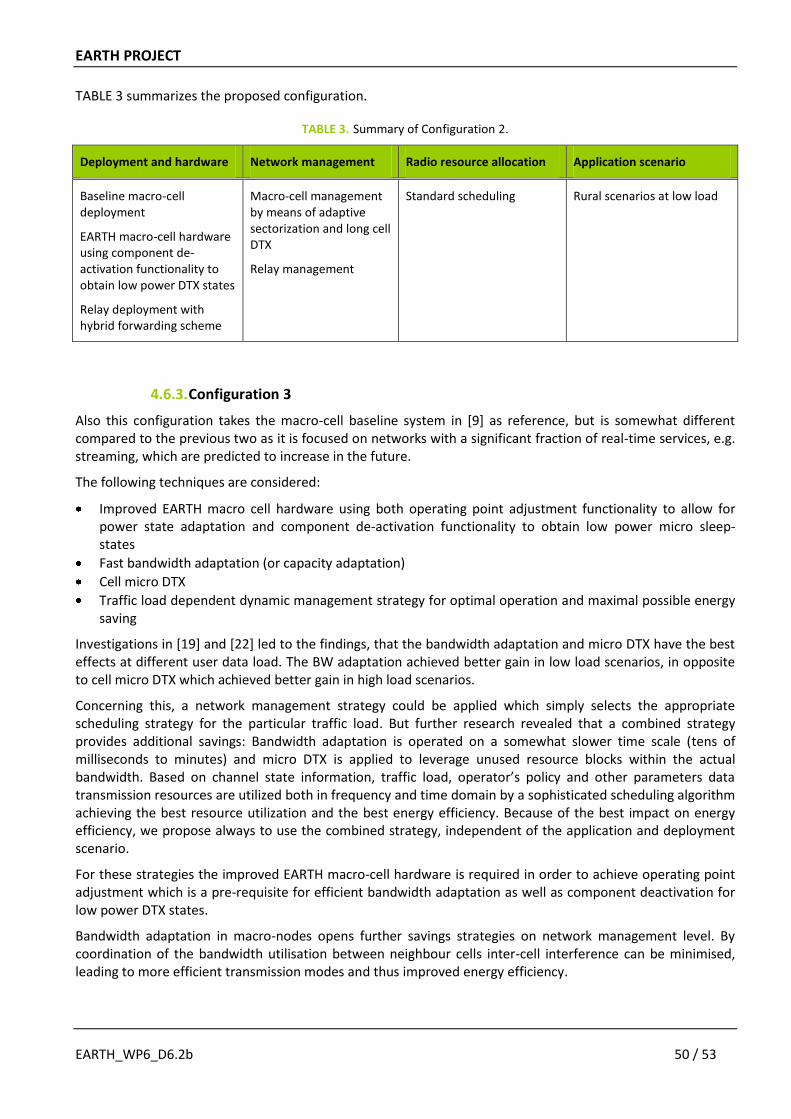
EARTH PROJECT
EARTH_WP6_D6.2b 50 / 53
TABLE 3 summarizes the proposed configuration.
TABLE 3. Summary of Configuration 2.
Deployment and hardware Network management Radio resource allocation Application scenario
Baseline macro-cell deployment
EARTH macro-cell hardware using component de-activation functionality to obtain low power DTX states
Relay deployment with hybrid forwarding scheme
Macro-cell management by means of adaptive sectorization and long cell DTX
Relay management
Standard scheduling Rural scenarios at low load
4.6.3. Configuration 3
Also this configuration takes the macro-cell baseline system in [9] as reference, but is somewhat different compared to the previous two as it is focused on networks with a significant fraction of real-time services, e.g. streaming, which are predicted to increase in the future.
The following techniques are considered:
Improved EARTH macro cell hardware using both operating point adjustment functionality to allow for power state adaptation and component de-activation functionality to obtain low power micro sleep- states
Fast bandwidth adaptation (or capacity adaptation)
Cell micro DTX
Traffic load dependent dynamic management strategy for optimal operation and maximal possible energy saving
Investigations in [19] and [22] led to the findings, that the bandwidth adaptation and micro DTX have the best effects at different user data load. The BW adaptation achieved better gain in low load scenarios, in opposite to cell micro DTX which achieved better gain in high load scenarios.
Concerning this, a network management strategy could be applied which simply selects the appropriate scheduling strategy for the particular traffic load. But further research revealed that a combined strategy provides additional savings: Bandwidth adaptation is operated on a somewhat slower time scale (tens of milliseconds to minutes) and micro DTX is applied to leverage unused resource blocks within the actual bandwidth. Based on channel state information, traffic load, operator’s policy and other parameters data transmission resources are utilized both in frequency and time domain by a sophisticated scheduling algorithm achieving the best resource utilization and the best energy efficiency. Because of the best impact on energy efficiency, we propose always to use the combined strategy, independent of the application and deployment scenario.
For these strategies the improved EARTH macro-cell hardware is required in order to achieve operating point adjustment which is a pre-requisite for efficient bandwidth adaptation as well as component deactivation for low power DTX states.
Bandwidth adaptation in macro-nodes opens further savings strategies on network management level. By coordination of the bandwidth utilisation between neighbour cells inter-cell interference can be minimised, leading to more efficient transmission modes and thus improved energy efficiency.
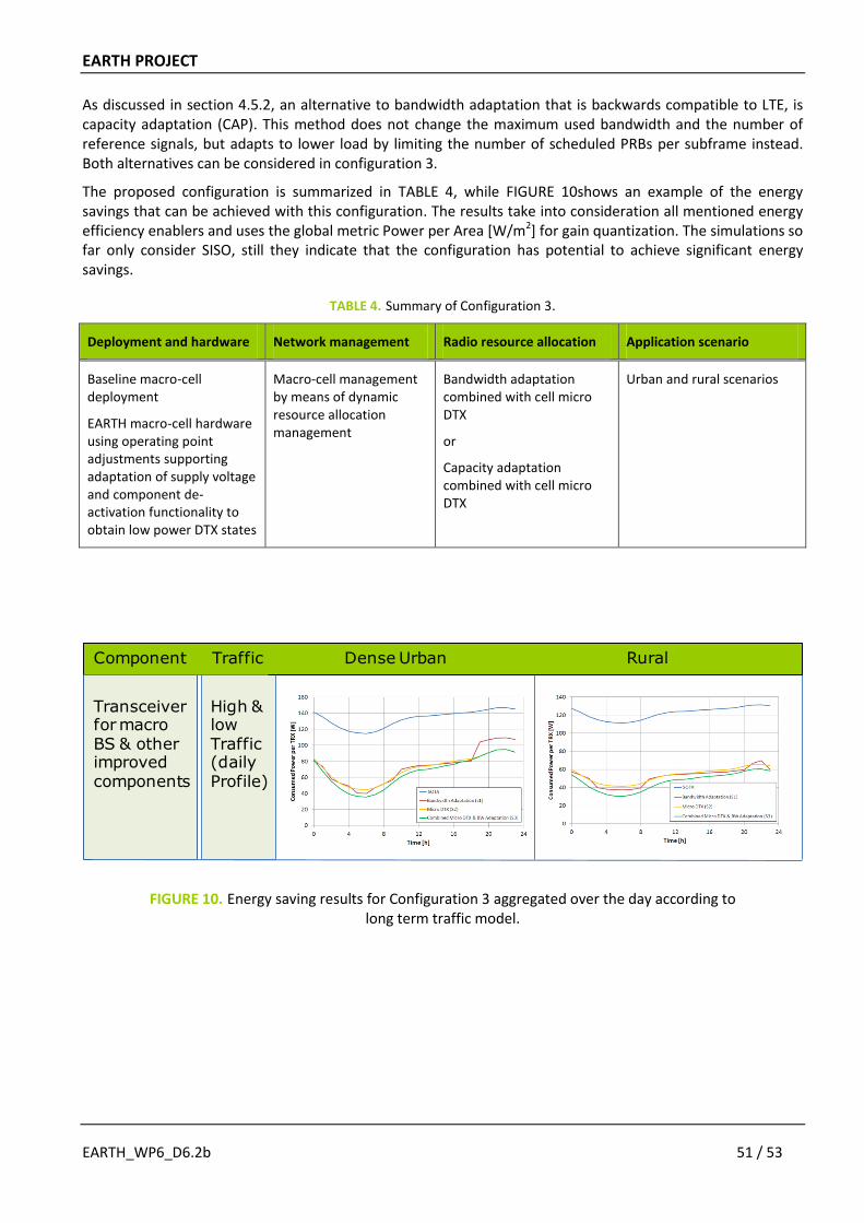
EARTH PROJECT
EARTH_WP6_D6.2b 51 / 53
As discussed in section 4.5.2, an alternative to bandwidth adaptation that is backwards compatible to LTE, is capacity adaptation (CAP). This method does not change the maximum used bandwidth and the number of reference signals, but adapts to lower load by limiting the number of scheduled PRBs per subframe instead. Both alternatives can be considered in configuration 3.
The proposed configuration is summarized in TABLE 4, while FIGURE 10shows an example of the energy savings that can be achieved with this configuration. The results take into consideration all mentioned energy efficiency enablers and uses the global metric Power per Area [W/m2] for gain quantization. The simulations so far only consider SISO, still they indicate that the configuration has potential to achieve significant energy savings.
TABLE 4. Summary of Configuration 3.
Deployment and hardware Network management Radio resource allocation Application scenario
Baseline macro-cell deployment
EARTH macro-cell hardware using operating point adjustments supporting adaptation of supply voltage and component de-activation functionality to obtain low power DTX states
Macro-cell management by means of dynamic resource allocation management
Bandwidth adaptation combined with cell micro DTX
or
Capacity adaptation combined with cell micro DTX
Urban and rural scenarios
High &lowTraffic(dailyProfile)
Transceiver for macro BS & other improved components
Dense Urban RuralTrafficComponent
FIGURE 10. Energy saving results for Configuration 3 aggregated over the day according to long term traffic model.
EARTH PROJECT
EARTH_WP6_D6.2b 52 / 53
5. CONCLUSIONS AND FURTHER WORK
In this deliverable it has been reported how the proof-of-concept work in EARTH will be carried out, and in particular how the work on EARTH integrated solutions is planned. Furthermore, work on defining draft EARTH integrated solutions has also been reported.
The EARTH proof-of-concept work will be carried out in two ways. The overall holistic evaluation of the EARTH energy efficient integrated solution will be carried out by means of radio network system level simulations according to the evaluation framework developed in the project. However, for certain EARTH building blocks it is seen necessary not to only rely on simulations, but to confirm the theoretical results by validation test in a realistic test environment. Those building blocks are represented by components or base stations, whose behaviour has to be validated. For this purpose, a mobile operator test plant designed to validate in tests node and component behavior of mobile network infrastructure will be utilized as complement to the radio network simulations.
The work on integrated solutions consists of three stages:
1) A conceptual stage, where the different building blocks are combined into suitable configurations tailored to application scenarios.
2) Evaluation, where the configurations are evaluated in these scenarios, and finally combined according to the evaluation framework in order to see the global impact of the EARTH integrated concept.
3) Visualization, where the results from the evaluations are presented in a pedagogic way.
The starting point for the conceptual stage has been the most promising tracks, which are the solutions and concepts that the project has identified as having highest energy saving potential. These were selected after the first year of activity in the project, in order to streamline the activities among the most promising research axes.
The definition of the first integrated solutions has commenced by sorting the energy efficiency enablers studied in the project according to their time scale of operation, and mapping them to the most suitable application scenario. Then strategies for all energy efficiency enablers have been formulated, and from these a number of suitable configurations have been defined. Some work has also been spent on identifying suitable measures that the adaptation between configurations for the different application scenarios can be based upon.
The next steps in this work are now to further identify and refine the suitable configurations, and then to implement them in the system simulators and start the evaluations. This will be the focus of the work on integrated solutions during the remainder of EARTH, and will be reported in the final deliverable [13].
EARTH PROJECT
EARTH_WP6_D6.2b 53 / 53
6. REFERENCES
[1] “ICT Facts and Figures: The World in 2010”, ITU-D, available via: http://www.itu.int/ITU-D/ict/material/FactsFigures2010.pdf
[2] “Cisco Visual Networking Index: Forecast and Methodology, 2009-2014”, Cisco white paper, June 2, 2010
[3] J. Malmodin, “The importance of energy in LCA for the ICT sector”, in Proc. of SETAC Europe 14th LCA Case Study Symposium, Göteborg, Sweden, December 2007
[4] M. Gruber, O. Blume et al, "EARTH – Energy Aware Radio and Network Technologies", in Proc. IEEE International Symposium on Personal, Indoor and Mobile Radio Communications (PIMRC), Cannes, France, September 2008
[5] J. T. Louhi and H.-O. Scheck, "Energy efficiency of cellular networks", in Proc. Int. Symp. Wireless Personal Multimedia Communications (WPMC), Lapland, Finland, Sep. 2008
[6] L. M. Correia, D. Zeller et al, "Challenges and Enabling Technologies for Energy Aware Mobile Radio Networks", IEEE Communications Magazine special issue on green radio, pp. 66-72, Nov. 2010
[7] EU funded research project EARTH (Energy Aware Radio and neTwork tecHnologies, FP7-ICT-2009-4-
247733-EARTH, Jan. 2010 to June 2012) https://www.ict-earth.eu
[8] EARTH project deliverable, D2.3 “Energy Efficiency Analysis of the Reference Systems, Areas of Improvements and Target Breakdown”, 2010
[9] EARTH project deliverable, D2.2 “Definition and Parameterization of Reference Systems and Scenarios”, 2010
[10] EARTH project deliverable, D3.1 “Most Promising Tracks of Green Network Technologies”, 2010
[11] EARTH project deliverable, D4.1 “Most Promising Tracks of Green Radio Technologies”, 2010
[12] EARTH project deliverable, D6.2a “Draft Integrated Solutions”, 2011
[13] EARTH project deliverable, D6.4 “Final Integrated Concept”, to appear June 2012
[14] 3GPP TR 36.814 v9.0.0, “Further advancements for E-UTRA. Physical layer aspects (Release 9)”, 3GPP, Technical Specification Group Radio Access Network, Mar. 2010
[15] WINNER II, “D6.13.7: Test Scenarios and Calibration Cases Issues 2”, Deliverable, IST-4-027756, December 2006
[16] EARTH project deliverable, D5.1 “Test scenarios and Validation Capabilities”, 2010
[17] EARTH project deliverable, D5.2 “Validation Platform Framework”, 2011
[18] EARTH project deliverable, D5.3 “Report on Validation”, to appear June 2012.
[19] EARTH project deliverable, D3.2 “Green Network Technologies”, 2011
[20] EARTH project deliverable, D3.3 “Final Report on Green Network Technologies”, to appear June 2012
[21] Jain, R., Chiu, D.M., and Hawe, W., “A Quantitative Measure of Fairness and Discrimination for Resource Allocation in Shared Systems”, DEC Research Report TR-301, 1984
[22] EARTH project deliverable, D4.2 “Green Radio Technologies”, 2011