
EAI 8800 Scientific Computing System, 1965 - Archive...
18
SYSTEM DESCRIPTION
Transcript of EAI 8800 Scientific Computing System, 1965 - Archive...
SYSTEM D E S C R I P T I O N

A New-Generation Computing System for Scientific Computation and Simuletio
The EAI 8800 Scientific Computing System is a new extremely-versatile 100-volt computing system tha extends the capabilities of analog and hybrid com- putation in both speed and control flexibility. Based on a completely new solid-state design approach aimed at taking fullest advantage of modern tech- nology, the EAl 8800 System truly is a NEW GEN-ERATION COMPUTING SYSTEM. Completely oper- ator-oriented for maximum convenience and effi- ciency of operation, the EAI 8800 System offers a greater problem-solving capability with a significant- ly higher accuracy and speed of computation than any other system available.

EAI 8800 Scientific Computing System
Summary of EAI 8800 Computing System Characteristics
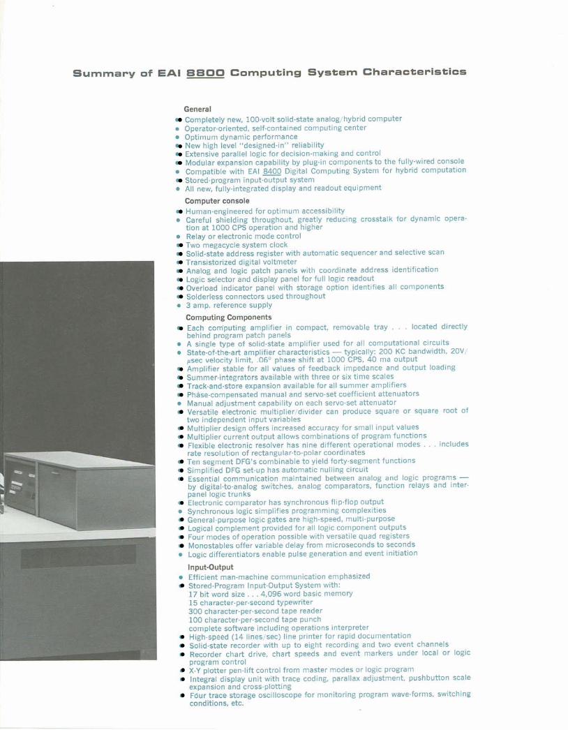
General Completely new, 100-volt solid-state analog/hybrld computer
0 Operator-oriented, self-contained computing center 0 Optimum dynamic performance
New high level "designed-in" reliability Extensive parallel logic for decision-making and control Modular expanslon capability by plug-in components to the fully-wired console
0 Compatible with EAI 8400 Digital Computing System for hybrid computation Stored-program input-output system
0 All new, fully-integrated display and readout equipment
Computer console Human-engineered for optimum accessibility
0 Careful shielding throughout, greatly reducing crosstalk for dynamic opera. tion at 1000 CPS operation and higher Relay or electronic mode control Two megacycle system clock Solid-state address register with automatic sequencer and selective scan Transistorized digital voltmeter Analog and logic patch panels with coordinate address identification Logic selector and display panel for full logic readout Overload indicator panel with storage option identifies all compnents Solderless connectors used throughout
0 3 amp. refwence supply
Computing Components Each computing amplifier in compact, removable tray . . . located directly behind program patch panels
0 A single type of solid-state amplifier used for all computational circuits State-of-the-art amplifier characteristics - typically: 200 KC bandwldth, 20V/ psec velocity limit, .OeO phase shift at 1000 CPS, 40 ma output Amplifier stable for all values of feedback impedance and output loading Summer-integrators available with three or six time scales Track-and-store expansion available for all summer amplifiers Phase-compensated manual and servo-set coefficient attenuators
0 Manual adjustment capability on each servo-set attenuator Versatile electronic multiplier/divider can produce square or square root of two independent input variables Multiplier design offers increased accuracy for small input values Multiplier current output allows combinations of program functions Flexible electronic resolver has nine different operational modes . . . includes rate resolution of rectangular-to-polar coordinates Ten segment DFG's combinable to yleld forty-segment functions Simplified DFG set-up has automatic nulling circuit Essential communication maintained between analog and logic programs - by digital-to-analog switches, analog comparators, function relays and inter- panel logic trunks Electronic comparator has synchronous flip-flop output
0 Synchronous logic simplifies programming complexities General-purpose logic gates are high-speed, multi-purpose Logical complement provided for all logic component outputs Four modes of operatlon possible with versatile quad registers Monostables offer variable delay from microseconds to seconds
0 Logic differentiators enable pulse generation and event initiation
Input-Output Efficlerrt man-machine communication emphasized Stored-Program Input-Output System with: 17 bit word size. . .4,096 word bas~c memory 15 character-per-second typewriter 300 character-per-second tape reader 100 character-per-second tape punch complete software including operations interpreter High-speed (14 lines/sec) line printer for rapid documentation Solid-state recorder with up to eight recording and two event channels Recorder chart drlve, chart speeds and event markers under local or logic program control X-Y plotter pen-llft control from master modes or logic program Integral display unit with trace coding, parallax adjustment, pushbutton scale expansion and cross-plotting Four trace storage oscilloscope for monitoring program wave-forms, switching conditions, etc.

The EAI 8800 Scientific Computing System
Improved dynamic performance . . . increased bandwidth, augmented by high-speed switch- ing circuitry and extremely fast logic, is made possible by the compactness of solid-state electronics.. .with most components packaged directly behind the patch panels. The system's excellent dynamic performance can be used for broader repetitive operation programs, for high-speed iterative loops within a larger problem . . . especially where partial differential equations are involved . . . and for complex hybrid applications.
Programming versatility . . . this system gives to the programmer the potential for handling the ever-growing complexities of modern scientific computation through its improved design concepts . . . a completely operator-oriented input-output capability . . . solid-state mode control and time scale selection on three levels . . . a multi-purpose complement of high- speed logic elements for decision-making and control . . . and a variety of readout, recording and display devices fully-integrated for highly automated operation.
Excellent reliability . . .the EAI 8800 Computing System is a quality-assured system backed up by a thorough program of testing, evaluation, debugging and correction in each step of manufacture - component, sub-assembly and system. This quality assurance is further enhanced by the "designed-in" reliability features of the system . . . complete elimination of vacuum-tubes . . . solid-state mode control and readout selection system . . . new connec- tor concepts which virtually eliminate soldered connections . . . short-proof reference voltage . . . amplifier output protection . . . rigorous life-test standards, etc. . . . all of which contribute to the achievement of new levels of computer reliability.
Input-Output capability . . . this system integrated with the new and powerful EAI Input-Out-put System is a complete computing center that is uniquely suited for solving increasingly complex problems more rapidly than ever before. The Input-Output System provides com- plete monitoring and control of the analog/hybrid system with the additional feature of in- dependent stored-program computation.
Expansion .. . the EAI 8800 Computing System offers, in its versatile, modular-design con- cept, a component-expansion capability that insures i ts continued capacity to handle tomor- row's more-advanced applications. All components may be added on a plug-in basis t o the fully-wired console which is part of the basic EAI 8800 System.
Readout . . . in terms of peripheral equipment too, the EAI 8800 System has capabilities that provide a new dimension in fast, flexible and efficient computer utilization. The com- puter console, human-engineered for maximum operating convenience and efficiency itself, contains additional design features which insure that all readout and display equipment also offer maximum accessibility to the operator. A modular expansion desk, providing conven- ient visual display of the computer outputs, contains such units as a multi-channel display, monitor/display scope, a high-speed printer and an 11x 17 inch X-Y recorder. In addition, a separate, high-precision multi-channel recorder is available to provide simultaneous recti- linear display of up to eight analog input channels and two timing or event channels.
Thus, in keeping with its overall design concept of a "self-contained-computing center", the EAI 8800 System provides complete capabilities for increased programming efficiency and versatility, improved reliability, and extended input-output performance features.
GI 1965 Electronic Associatea, Inc., All Rights Resewed

PERFORMANCE, RELIABILITY, VERSATILITY
The EAI 8800 Scientific Computing System is the culmination of the design evo- lution in analog/hybrid computer development, an evolutian which has been char- acterized by improved human-engineering . . . by solid-state reliability . . . by high. accuracy dynamic performance . . . by high-speed electronic mode control . . .and by parallel synchronous logic.
Highly efficient man-machine communication and the advanced computing tech- niques realized with the EAI 8800 System make possible more efficient programming and, as a result, more problem solutions per unit of time. By cutting time and costs in programming, in checking, and in operation, this powerful computing system expands the number of problems that can be undertaken in a simulation laboratory, making available the use of its facilities to more engineers and scientists. In addi-tion, the sizeable expansion capability of the system, provided through its modular- design features, offers the necessary versatility to solve problems of widely vary- ing magnitude from routine calculations to the most sophisticated simulations.
The system yields a computing capability to handle problems of larger scope, of greater speed requirements, and of more complexity than ever before available plus sufficient power to handle the more advanced problems which will continue to arise. This is only possible through its embodiment as one, completely new, next- generation machine, achieving its rigorous design goals based on the la ta t knowl- edge and experience available in all aspects of analog and hybrid computation.
Computer Console
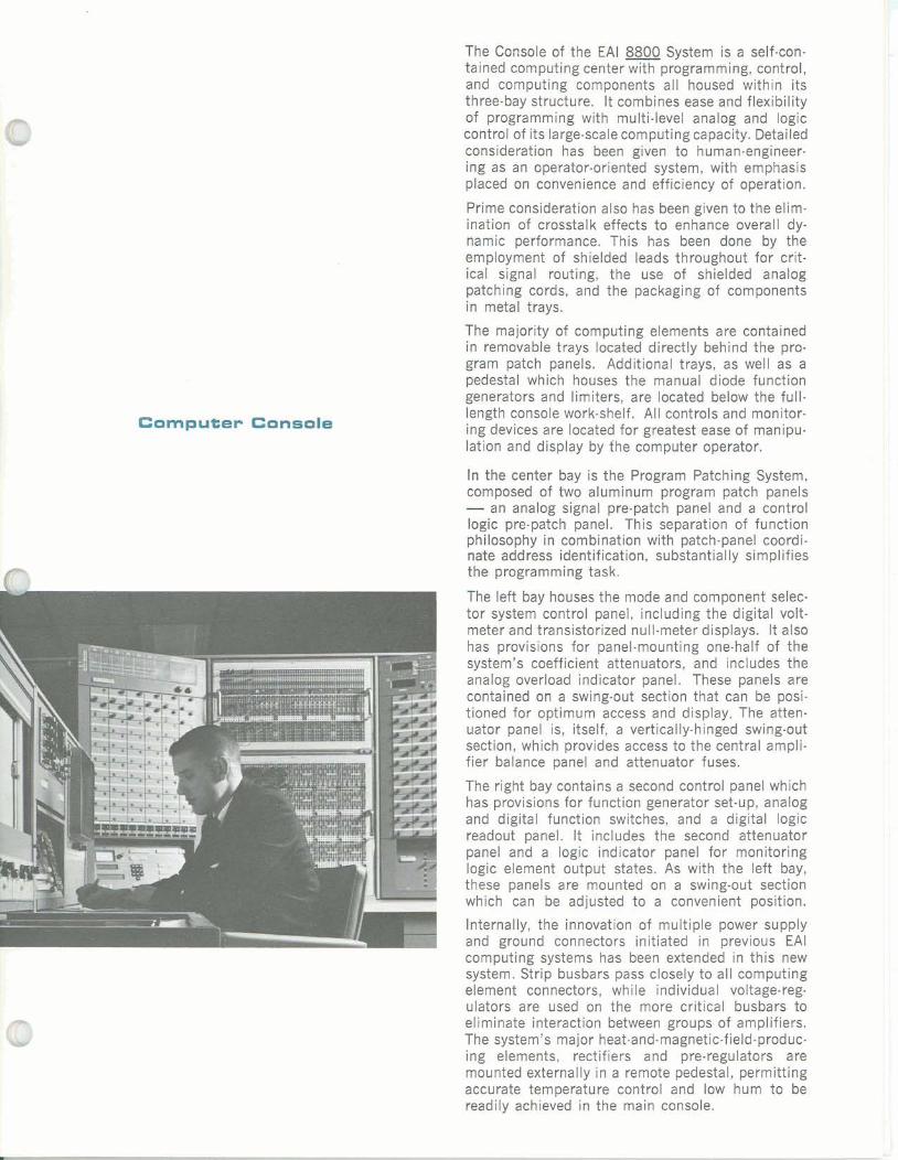
The Console of the EAI 8800 System is a self-con- tained computing center with programming, control, and computing components all housed within its three-bay structure. It combines ease and flexibility of programming with multi-level analog and logic control of its large-scale computing capacity. Detailed consideration has been given to human-engineer-ing as an operator-oriented system, with emphasis placed on convenience and efficiency of operation.
Prime consideration also has been given to the elim- ination of crosstalk effects to enhance overall dy- namic performance. This has been done by the employment of shielded leads throughout for crit- ical signal routing, the use of shielded analog patching cords, and the packaging of components in metal trays.
The majority of computing elements are contained in removable trays located directly behind the pro- gram patch panels. Additional trays, as well as a pedestal which houses the manual diode function generators and limiters, are located below the full- length console work-shelf. All controls and monitor- ing devices are located for greatest ease of manipu- lation and display by fhe computer operator.
In the center bay is the Program Patching System, composed of two aluminum program patch panels -an analog signal pre-patch panel and a control logic pre-patch panel. This separation of function philosophy in combination with patch-panel coordi- nate address identification, substantially simplifies the programming task.
I tor system control panel, including the digital volt- meter and transistorized null-meter displays. It also has provisions for panel-mounting one-half of the system's coefficient attenuators, and includes the analog overload indicator panel. These panels are contained on a swing-out section that ca.n be posi- tioned for optimum access and display. The atten- uator panel is, itself, a vertically-hinged swing-out section, which provides access to the central ampli- fier balance panel and attenuator fuses.
The right bay contains a second control panel which has provisions for function generator set-up, analog and digital function switches, and a digital logic readout panel. I t includes the second attenuator panel and a logic indicator panel for monitoring logic element output states. As with the left bay, these panels are mounted on a swing-out section which can be adjusted to a convenient position.
Internally, the innovation of multiple power supply and ground connectors initiated in previous EAI computing systems has been extended in this new system. Strip busbars pass closely to all computing element connectors, while individual voltage-reg-ulators are used on the more critical busbars to eliminate interaction between groups of amplifiers. The system's major heat-and-magnetic-field-produc-ing elements, rectifiers and pre-regulators are mounted externally in a remote pedestal, permitting accurate temperature control and low hum to be readily achieved in the main console.
Computing Components
The many desirable characteristics of the EAI 8800 Scientific Computing System are evidenced in each analog and logic computing component contained in the system. Designed for optimum reliability, these devices, as the natural extensions of proven EAI equipment presently in use, offer excellent static and dynamic performance combined with the maximum possible versatility in operational use.
A solid-state, 100-volt operational amplifier is used for all computational circuits. To insure highly re- liable operation of this device, quality components are used throughout. Furthermore, the most recent developments in high-frequency components have been studied, evaluated, and employed wherever possible. As a result, the amplifier offers state-of- the-art operating characteristics . . . a typical small signal bandwidth of 200 KC, 20V/,~sec velocity limit, 0.06" phase shift at 1000 CPS, 40 ma out- put, and unconditional stability for all values of output capacitance and for any feedback imped- ance. The same degree of design care has been applied to all amplifier-associated linear and non- linear networks . . . summers, summer-integrators, function generators, resolvers, multipliers, etc.
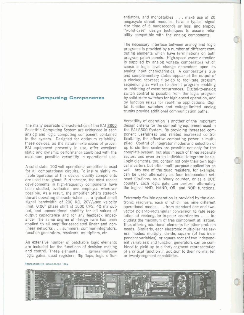
An extensive number of patchable logic elements are included for the functions of decision making and control. These elements . . . general-purpose logic gates, quad registers, flip-flops, logic differ-
Representative Cnrnponent Tray
entiators, and monostables . . . make use of 20 megacycle circuit modules, have a typical signal rise time of 5 nanoseconds or less, and employ "worst-case" design techniques to assure relia-bility compatible with the analog components.
The necessary interface between analog and logic programs is provided by a number of different com- puting elements which have terminations on both program patch panels. High-speed event detection is supplied by analog voltage comparators which cause a logic level change dependent upon its analog input characteristics. A comparator's true and complementary states appear at the output of a clocked set-reset flip-flop to facilitate program sequencing as well as to permit program enabling or inhibiting of event occurrences. Digital-to-analog switch control is possible from the logic program by solid-state switches for high-speed operation, and by function relays for real-time applications. Digi- tal function switches and voltage-limited analog trunks provide additional communication paths.
Versatility of operation is another of the important design criteria for the computing equipment used in the EAI 8800System. By providing increased com- ponent usefulness and related increased control flexibility, the effective computing power is multi- plied. Control of integrator modes and selection of up to six time scales are possible not only for the complete system, but also in each of three separate sectors and even on an individual integrator basis. Logic elements, too, contain not only their own logi- cal inverters but offer multi-purpose application as well. Any one of the quad registers, for example, can be used alternately as four independent set- reset flip-flops, as a binary counter, or as a BCD counter. Each logic gate can perform alternately the logical AND, fVAND, OR, and NOR functions.
Extremely flexible operation is provided by the elec- tronic resolvers, each of which has nine different operational modes . . . from standard one and two- vector polar-to-rectangular conversion to rate reso- lution of rectangular-to-polar coordinates . . . in-cluding the maximum of free component utilization, thus offering additional elements for other problem needs. Similarly, each electronic multiplier has sev- eral modes: multiply, divide, square (of two inde- pendent variables), or square root (of two independ- ent variables); and function generators can be com- bined to yield up to a forty-segment representation of a critical function in addition to their normal ten or twenty-segment capabilities.
EAl 8840 Input-Output Sg~tem
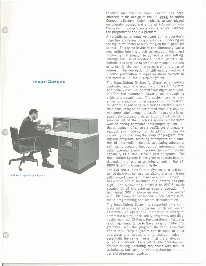
Efficient man-machine communication has been stressed in the design of the EAI 8800 Scientific Computing System. Major emphasis has been placed on operator access and entry of information into the system in order to enhance the rapport between the programmer and his problem. A versatile serial-input keyboard at the operator's fingertips addresses components for monitoring on the digital voltmeter or outputting on the high-speed printer. This same keyboard can alternately load a new setting into the precision voltage divider, and instruct an attenuator to achieve a new setting. Through the use of additional control panel push- buttons, it is possible to scan all component outputs or to restrict the scanning process only to areas of interest. The depression of still another keyboard function pushbutton relinquishes these controls to the versatile EAI Input-Output System. The Input-Output System functions as a digitally controlled automatic set-up and check-out system. Additionally useful as a small-scale digital computer, it offers the operator a powerful tool through its arithmetic capabilities. The system can be used either for analog computer input-output or, by itself, to perform engineering calculations too tedious and time consuming to be performed manually and yet not complicated enough to justify the use of a large- scale data processor. As an input-output device, it provides all of the functions normally associated with an analog computer input-output system . . . the adjustment of servo-set coefficient attenuators, readout, and mode control. In addition, it has the capability for checking the computer program, stor- ing run programs, resetting attenuators as a func- tiin of intermediate results, calculating attenuator settings, processing input-output information, and other operations which require the computational capability of a small-scale digital computer. The Input-Output System is designed to operate both in- dependently of and as an integral unit in the EAI -8800 Scientific Computing System. The EAI 8840 Input-Output System is a self-con- tained desk-type console, consisting of a main frame with control panel and 4096 words of memory. It has a word size of seventeen bits (sixteen bits plus sign). The typewriter supplied is an IBM Selectric capable of 15 character-per-second operation. A high-speed 300 character-per-second tape reader and 100 character-per-second punch permit auto- matic programming and record documentation. The Input-Output System is supported by a com- plete set of software programs which include an assembler, an operations interpreter, a library of arithmetic sub-routines, utility programs, and diag- nostic routines. Of these, the operations interpreter is of major importance to the analog computer pro- grammer. With this program, the various controls of the Input-Output System can be used to enter addresses and values, and to change modes in essentially the same manner that the analog com- puter is operated. As a result, the operator can prepare analog operating sequences with familiar techniques, but have the whole system operate un- der stored-program control.
SYSTEM OPERATIONAL CHARACTERISTICS
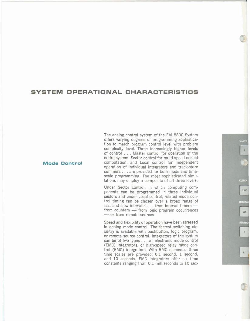
Mode Control
The analog control system of the EAI 8800 System offers varying degrees of programming sophistica- tion to match program control level with problem complexity level. Three increasingly higher levels of control . . . Master control for operation of the entire system, Sector control for multi-speed nested computation, and Local control for independent operation of individual integrators and track-store summers. . . are provided for both mode and time- scale programming. The most sophisticated simu- lations may employ a composite of all three levels.
Under Sector control, in which computing com-ponents can be programmed in three individual sectors and under Local control, related mode con- trol timing can be chosen over a broad range of fast and slow intervals . . . from interval timers -from counters - from logic program occurrences -or from remote sources.
Speed and flexibility of operation have been stressed in analog mode control. The fastest switching cir- cuitry is available with pushbutton, logic program, or remote source control, Integrators of the system can be of two types . . . all-electronic mode control (EMC) integrators, or high-speed relay mode con- trol (RMC) integrators. With RMC elements, three time scales are provided: 0.1 second, 1 second, and 10 seconds. EMC integrators offer six time constants ranging from 0.1 milliseconds to 10 sec-
onds in decade steps. Significantly, to meet the changing demands of future requirements at com- puter laboratories, the RMC integrators can be read- ily converted to EMC integrators and vice versa, by the simple replacement of plug-in network modules. Either type of integrator can be used individually as a track-store device under independent control.
Summer amplifiers in the EAI 8800 System offer similar flexibility . . . as standard summers, they contain RMC circuitry; when a summer is to be used also as a track-store device, it is supplied as an EMC unit with two storage capacitors. In this man- ner, optimum performance of the track-store sum- mer is obtained for real-time and high-speed com- putation as a point storage device, or for comple- mentary operation with any other EMC summer.
For further convenience and efficiency of operation the Pot Set mode facilitates the accurate setting of attenuators, the Rate Test mode permits the inte- grating rate of all integrators in the computer to be checked, and the Static Test mode provides static test voltages for problem check out.
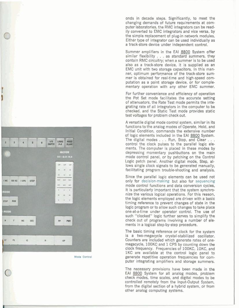
A versatile digital mode control system, similar in its functions to the analog modes of Operate, Hold, and Initial Condition, commands the extensive number of logic elements included in the EAI 8800 System. The digital modes . . . Run, Stop, and Clear . . . control the clock pulses to the parallel logic ele- ments. The computer is placed in these modes by depressing momentary pushbuttons on the main mode control panel, or by patching on the Control Logic patch panel. Another digital mode, Step, al- lows single clock signals to be generated manually, facilitating program trouble-shooting and analysis.
Since the parallel logic elements can be used not only for decision-making but also for sequencing mode control functions and data conversion cycles, it is particularly important that the system synchro- nize the various logical operations. For this reason, the logic elements employed are driven with a basic timing reference to prevent changes of state in the logic program or to allow such changes to take place one-at-a-time under operator control. The use of such "clocked" logic further serves to simplify the check out of programs involving a number of ele- ments in a logical step-by-step procedure.
The basic timing reference or clock for the system is a two-megacycle crystal-stabilized oscillator. Counters are included which generate rates of one- megacycle, lOOKC and 1CPS by counting down the clock frequency. Frequencies of IOOKC, lOKC, and 1KC are available at the control logic panel to generate repetitive operation frequencies for com- puter integrating amplifiers and storage summers.
The necessary provisions have been made in the EAI 8800 System for all analog modes, problem check modes, time scales, and digital modes to be controlled remotely from the Input-Output System, from the digital section of a hybrid system, or from other analog computing systems.

Programming
Since a significant portion of the overall problem- solving cycle for a general purpose analog computer is devoted to programming, emphasis has been placed on efficiency in design of the program patch- ing system of the EAI 8800 Computing System. It fea-tures a 4,080 terminal analog pre-patch panel and a 2,400 hole control logic pre-patch panel, both of which can be replaced in seconds with full assur- ance of electrical continuity on all contacts.
Extensive programming and patching flexibility is offered by the multiple input and output termina- tions, fully-shielded analog patching elements, fan- out logic patch cords, a coordinate address format, and new dual-purpose spring contacts which allow necessary connections to be made with a minimum number of patching operations. Further assistance in programming is provided by a consistent color- coding scheme used in conjunction with bold high- contrast lettering to provide maximum legibility for patching terminal identification.
The layout of the panels is aimed at grouping all types of computing elements and their controls in repeated patterns so that patch cord lengths are minimized. As a result, patch panel clutter is re-duced by the many connections which can be made with patching plugs, and by the significant number of connections which can be made with multi-con- tact patching springs, permitting multiple closures to be actuated by the insertion of a single patch cord. The identification of computing elements is accomplished by a coordinate address system, allow- ing quick location of any component. This is fur- ther aided by the arrangement of overload and logic- state indicators, which are directly related to the patch panel location of components.
A significant portion of analog computer program- ming time is also related to the set up of problem coefficients, and it is of considerable value to fa- cilitate this phase. This requirement is properly met in the EAI 8800 System with the Digital Attenu- ator System. Used in conjunction with the console's input-output system, the Digital Attenuator System enables the operator to make automatic selections and adjustments of servo-set coefficient attenuators . . . from punched tape by the EAI Input-Output System or another digital computer. Furthermore, manual setting can be accomplished at the console from the input keyboard, or actually at the attenua- tor since each unit has its own manual adjustment capability. This flexibility permits operator to make continuous parameter changes during a problem run.
Completely automatic control of many aspects of the computer programming process is possible from punched tape on the EAI Input-Output System. Ini- tiation of mode changes (in both analog and logic mode control systems), time scale selection, atten- uator setting, and documentation of interim and final problem results are some of the time-saving operations that can help to simplify programming.

Readout and Display
The very necessary man-machine communication involving the display and documentation of prob-lem results has been another area of particular emphasis in the design of the EAI 8800 Computing System. Recognizing the need not only for the 'avail- ability' of results but also for their accurate and reliable presentation, EAI offers a complete selec- tion of equipment to satisfy these requirements. This equipment is fully integrated into the system, thus eliminating the additional programming burden usu- ally associated with peripheral devices.
The readout system of the EAI 8800 System utilizes a high-speed, solid-state digital voltmeter, single reed-relay contacts for each readout point and a set of solid-state shift registers with decoding matrix for high-speed scanning of analog outputs. Both values and addresses of all outputs, including inte- grator initial derivations, are available in visual and electrical form for local monitoring, remote selec- tion and display at the Input-Output System or a dig- ital computer. A sequential scan mode in conjunc- tion with the EAI 8860 Printer can be used for direct high-speed (14 line-per-second) readout on hard copy. The readout system can be used at even faster rates for entry into digital computer memory. A particularly useful feature of the scanning system is that missing elements are passed by in less than a millisecond without recording.
To provide a complete computational system, a va- riety of peripheral devices are available:
X-Y Recorders . . . the EAI 8850 transistorized 11" x 17" X-Y Recorder plots one or more inde-pendent variables as functions of time or any other independent variable -provides accurate graphic recording of computer solutions . . . has continu- ously variable scale factor control, pen and arm ori- gin can be set anywhere on plotting surface, pen lift can be controlled by computer mode control sys- tem, scale extension or suppression permits plotting in any desired quadrant within a 30" x 45" area.
Time Base Recorder . . . the EAI 8875 Eight Channel Recorder represents a revolutionary ad- vance in all-solid-state direct-writing oscillographic design, in which recorder control functions are fully integrated with the computing system to pro- vide centralized control of computation and readout . . . offers rectilinear display of up to eight analog channels and two timing or event channels (80 mm channels are available for expanded displays), max- imum recording linearity within 0.5%, selection of twelve chart speeds, local or logic panel control of chart drive, chart speeds and event markers -compatible with any analog computing system.
Multi-Channel Display Unit . . . the EAI 8880 Display Unit is a self-contained precision display system featuring high resolution and accuracy, and wide bandwidth. Employing a 14-inch oscilloscope, this unit provides simultaneous display of four in-

dividually-coded traces of 18 possible inputs, ad- justment of display parallax, selection of sweep time from computer patch panel, a versatile cross- plotting capability, and display mode controls which facilitate interpretation of high-speed solutions.
Monitor' Display . . . a four-trace storage oscillo- scope, the EAI 8881 Monitor Display forms an integral part of the computing system to monitor program wave-forms switching conditions, voltages, etc. . . . has two megacycle bandpass and variable sweep range, single sweep operation, a variety of trigger facilities, . . . can be slaved to repetitive display unit for photographic recording purposes.
Display and Readout Equipment

The modular design concept of the EN 8800 Sci-entific Computing System provides a growth poten- tial which allows the customer to establish a mod- est-sized installation initially and to expand later as the workload and problem complexity dictate.
Each system is fully-wired at EAI for the maximum equipment expansion. All components can be added to the system in the field on a simple plug-in basis with no additions of wiring harnesses, soldering, etc. required. Additional peripheral equipment can be quickly and easily connected in the same manner.
Full slaving capability is another of the ready-ex- pansion features of the EAI 8800 Computing Sys- tem. With the addition of the standard cables, it is possible to slave the mode control, the time scaling system, and the 100 volt reference supply to any one of six other EAI 8800 Systems.
Further expansion into a large-scale hybrid com-puting facility is also readily possible for all users of the EAI 8800 Analog Computing System with the addition of the EAI 8400 Digital Computing System . . . a digital computer developed expressly for oper- ation in the real-time simulation environment. To-gether these systems form an extremely powerful, completely integrated hybrid computer with full soft. ware support and system responsibility provided by EAI as a total system supplier.
Expansion
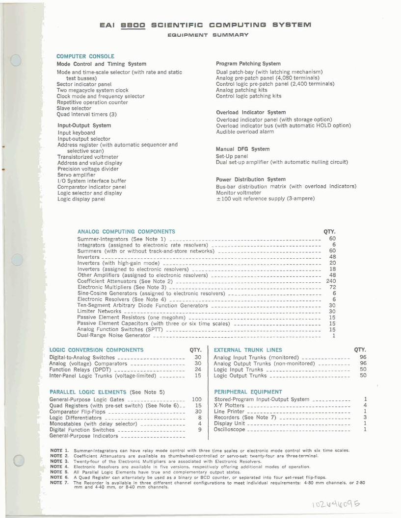
EAI 8800 SCIENTIFIC COMPUTINQ SYSTEM EDUIPMENT SUMMARY
- GOMPUTER CONSOLE I Mode Control and Timing System Program Patching System
Mode and time-scale selector (with rate and static Dual patch-bay (with latching mechanism) test busses) Analog pre-patch panel (4,080 terminals)
Sector indicator panel Control logic pre-patch panel (2,400 terminals){ Two megacycle system clock Analog patching kits
Clock mode and frequency selector Control logic patching kits 1 Repetitive operation counter
Slave selector ' Quad interval timers (3) Overload Indicator System
Overload indicator panel (with storage option) Input-Output System Overload indicator bus (with automatic HOLD option) lnput keyboard Audible overload alarm lnput-output selector Address register (with automatic sequencer and
selective scan) Manual DFG System Transistorized voltmeter Set-Up panel Address and value display Dual set-up amplifier (with automatic nulling circuit) Precision voltage divider Servo amplifier I/Q System interface buffer Power Distribution System Comparator indicator panel Bus-bar distribution matrix (with overload indicators) Logic selector and display Monitor voltmeter Logic display panel -c 100 volt reference supply (3-ampere)
QTY. EXTERNAL TRUNK LINES Qn. 'I Ihl"@tal-to-Analog Switches -------------. - 30 Analog Input Trunks (monitored) - -------- -- - 96
. &mlog (voltage) Comparators ----------------- 30 96Analog Output Trunks (non-monitored) -------,--,' Function Relays (DPDT) 24 Logic Input Trunks 50---------,--------, Vnter-Panel Logic Trunks (voltage-limited) -------- Logic Output Trunks --,----------------------15 50
P4RALLPL LOGIC ELEMENTS (See Note 5) PERIPHERAL EQUIPMENT ' Beneral-Purpose Logic Gates -----,------------Stored-Program Input-Output System 100 ------------' 'Q@ Registers (with pre-set switch) (See Note 6)-- 15 X-Y Plotters --------------------------------
Emparator Flip-Flops ........................ 30 Line Printer -------,,-----------------------Lwie Differentiators ---,-------------------8 Recorders (See Note 7) . . . . . . . . . . . . . . . . . . . . . . ~onostables (with delay selector) -------,----,,Display Unit . ...............................4 D&ital ,Function Switches ..................... 9 Oscilloscope -----------.. Qweral-Purpose Indicators . . . . . . . . . . . . . . . . . . . .
1. Bummer-Integrators can have relay mode control with three time soales or electronic mode control with six time scales. 2. Coefficient Attenuators are available as thumbwheel-controlled or servo-set; twenty-four are three-terminal.
' &@fE3. Twenty-four af the Electronic Multipliers are associated with Electronic Resolvers.
4. Electronic Resobers are available in five versions, respectively offering add~tional modes of operation. , W E 5. All Parallel Logic Elements have true and complementary output states.
6i A Quad Register can alternately be used as a binary or BCD counter, w separated into four set-reset flip-flops. NOTE 7. The Recorder is available in three different channel configurations to meet individual requirements: 4-80 mm channels, or 2-80
rnm and 4-40 mm. or 8-40 m m channels.

ADVANCED SYSTEMS ANALYSIS AND COMPUTATION SERVICESIANALOG COMPUTERSIDIGITAL COMPUTERSlHYBRlO ANALOG.DIGITAL COMPUTATION EQUIPMENTIANALOG AND DIGITAL PLOTTERSISIMULATION SYSTEMSISCIENTIFIC AND LABORATORY INSTRUMENTSIINDUSTRIAL PROCESS CONTROL SYSTEMS1 PHOTOGRAMMETRIC EQUIPMENTI RANGE INSTRUMENTA- TION SYSTEMSITEST AND CHECK-WT SYSTEMSIMILITARY AND INDUSTRIAL RESEARCH AND DEVELOPMENT SERVlCESlFlELD ENGINEERING AND EQUIPMENT MAINTENANCE SERVICES.
Printed in U.S.A. Bullet in No. AC 65028 - l May, 65


![INVESTIGATING FACTORS INFLUENCING DECISION MAKERS … · Application Integration [EAI], Service Oriented Architecture [SOA] and more recently – Cloud Computing) has highly influenced](https://static.fdocuments.in/doc/165x107/5c67f7ac09d3f23a018cad28/investigating-factors-influencing-decision-makers-application-integration-eai.jpg)

