E94ARNE Regenerative power supply 13-24A - Lenzedownload.lenze.com/TD/E94ARNE__Regenerative power...
62
EDK94ARN24 .P#T Ä.P#Tä লᴰᲸ Mounting Instructions 9400 13 ... 24 A l E94ARNE0xx4 ᯙᙺᏜሿษ౧Ꭳᅩ Regenerative power supply module L-force Drives
Transcript of E94ARNE Regenerative power supply 13-24A - Lenzedownload.lenze.com/TD/E94ARNE__Regenerative power...
EDK94ARN24.P#T
Ä.P#Tä
����
Mounting Instructions
9400 13 ... 24 A
�
E94ARNE0xx4
�����
Regenerative power supply module
L−force Drives

� �������������!
������������.
� Please read these instructions before you start working!
Follow the enclosed safety instructions.
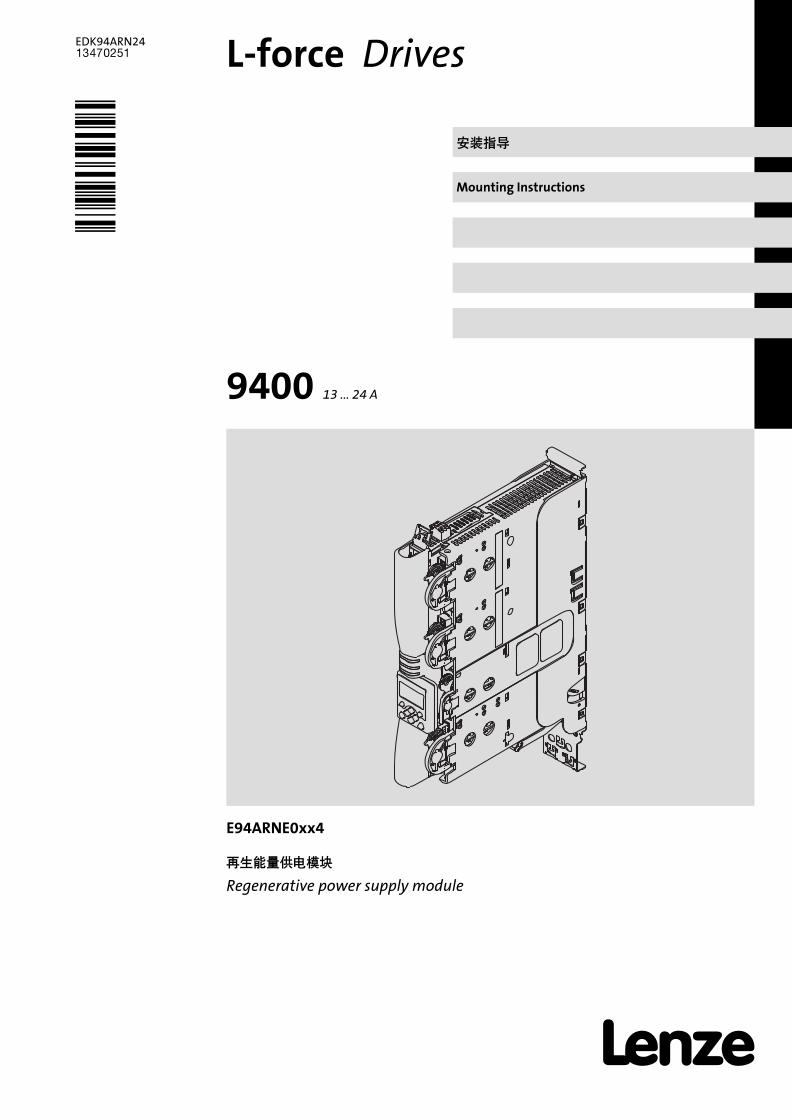
SSP94RN012
� 4 EDK94ARN24 ZH/EN 2.1
��
���� � ��
�� �� VR �
MXI1 �� 1���� � �
MXI2 �� 2���� � �
MMI ��� �
MSI � �
X1 ���� (CAN)���� �
X2 24 V ������ �
X3 ����������� 2/2
X4 ����� 4
X5 ����� 8
X6 �� �
X7 �������� �
X8 ������������� �
� �� �
� ��!" �
� �� �
� #�$��%���&� �
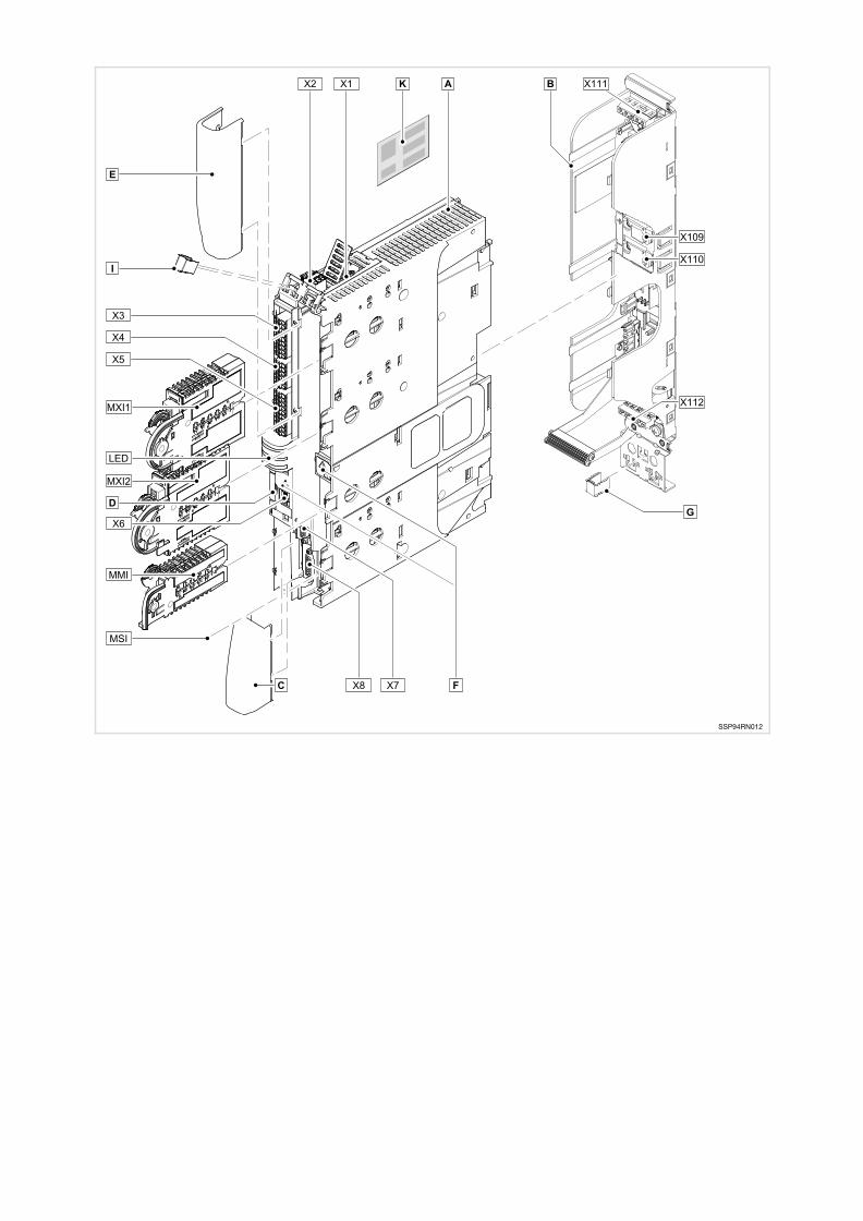
LED%'()��*%'�� !���"
LED �� �� ��
CAN−RUN +, CAN��o.k.-"StateLine".���#)��"
CAN−ERR $, CAN��%/
DRIVE READY +, �����0�
DRIVE ERROR $, ����%&����%
24 V +, 24−V ' o.k.
SSP94LED01 USER (, ��)�#*�1
�� �� ��
��� !: � ��+,3-�2�3� �.�45 �67 �!
� ���"#: /*��PE8012EN 61800−5−1���
� $�%&��: !�9!"��#�#�3$:4%5#�6 !
��'( ��
�� �� VR �
X111 7& ����/';<� �� �' �
X112 7& ����/�8�9 (� �' : �;< �
X109 ';<= +�X110 ';<= −
� EMC (=> �
© 2014 Lenze Automation GmbH, Postfach 10 13 52, D−31763 Hameln, Hans−Lenze−Str. 1, D−31855 Aerzen
?>@#)"?�Lenze Automation GmbH�@ABC �DE�AB)&�*CFD�E�1.
>F+3��G�1HC,-I�12���.@�J@GH/K�I40LMN1J2"OKL )MP�N3#OQP4Q�3/�5QRSR"#,�GH+S�"
)* i
� 5EDK94ARN24 ZH/EN 2.1
1 +,-. 6
1.1 �67�1 6
1.2 >FTU 6
1.3 V�W 6
1.4 T89 6
1.5 :X*; 7
2 �/�� 8
2.1 OK' ���<U����:=Y> 8
2.2 V?67 9
2.3 UL&UR �������� 10
3 0123 11
3.1 �G@9�WX 11
3.2 ��G 13
3.3 Z��� [Y@ 15
3.4 ZA�G 16
4 ��4(5��678 17
5 ������ 18
6 97���� 19
7 97� 23
7.1 ��� 23
7.2 �� 28
7.3 ���� 29
8 :;<= 30
8.1 " 400 V � �\��[\]] 30
8.2 " 230 & 500 V � �\��[\]] 30
8.3 �<\#B 31

+,-.�67�1
1
� 6 EDK94ARN24 ZH/EN 2.1
1 +,-.
1.1 >?@AB
H���6^_
ƒ E94ARNE0134 � E94ARNE0244 CP)�' ��"
D�"^2 E94AZMR0xx4xDB ����
ƒ (� EDK94ZMR47XDB) >F.����_�6"
1.2 +,CD
EFG HI ��
13240129 1.0 03/2008 TD15 C<G
.P#T 2.1 08/2014 TD29 5`G
� 0J!
E�OKabc`�>F:J@aE� da http://www.Lenze.com���efb��FgcG�
KLMN
1.3 )�O
h>F12 IEC 364�H_2i9!j#k"
2idlefg�9!h�I�3/�JKLiM�iN�c`�Om�m]]:��!��9!"
1.4 PQRS
h>F��jklic-#m��1nPn
��oQ
R�-o1 + <U-R�+"��n1234.56
��
UL �� �pqS>"
UR �� �
p�
T@q0 � q0rst�1�r< T@��n� 16 = )uT@ 16
+,-.:X*;
1
� 7EDK94ARN24 ZH/EN 2.1
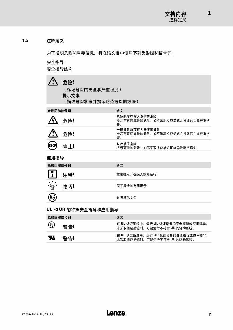
1.5 TUVW
_s��67�U/�1�v"h>F+-�jVWp���wn
�/��
����^xn
� XY!
��y67�nP�XUz{�
Z[+I
�tu67��|v'}~67�D��
\]^6AG_ `W
XY!XY�abcdefgXY
v'�'0wY�67��#qIx��yR�Zz{&XU|�"
� XY!hiXYjbcdefgXY
v'�'0wY�67��#qIx��yR�Zz{&XU|�"
� kl!mnopXY
v' )�67��#qIx��y )�Z�c}~"
qS��
\]^6AG_ `W
� TU! U/v'�:4�N39�
� 0J! ���9��v'
� )L��>F
UL 6 UR 5rs�/��6tS��
\]^6AG_ `W
� uv!c UL wxyz{|RL UL wx��5�/��}tS��~
�qIx��y.� )9�#12 UL ��9��"
� uv!c UL wxyz{|RL UR wx��5�/��}tS��~
�qIx��y.� )9�#12 UL ��9��"
�/��OK' ���<U����:=Y>
2
� 8 EDK94ARN24 ZH/EN 2.1
2 �/��
2.1 ���� 5hi�/6tST���
��Gn� ��� 2006/95/EC�
hi23
OK' ��"9��z+ )��� ���8@�I��4�nP��[?�@�{ )��"
�7AB�\�U/��m-#�m��9�%/�RcPXU�9�|�&U���c}~�7"
ab�1�)�H>F"
3��9�m�m]]:��!�3$&2idlefg�9!���3$]� IEC
364/CENELEC HD 384 & DIN VDE 0100 : IEC report 664 & DIN VDE 0110 #:��Y
N }�T�"
�G�H���1�2idlefg�9!f�c`�Om�m]]:���|I�3/�JKLiM�"
����tS
' ��H���" ���&#�+"�G EN 61000−3−2�' ��#��
� ��D)�!K�"H>F��s EN 61000−3−2 3T*��^xE�1"
v' ����#�,����7M�#�12 EC �� 98/37/EC�ZA����8
#�]]��������9��' ���r��$]� EN 60204"
D�12 EMC �� (2004/108/EC) .�__1��]]��������9��"
' ���`� ��� 2006/95/EC /K"EN 61800−5−1 �j�<����' �
�"
le�G�80k@�1 �!":>F+�*"3$Xi]�ab�G�k@"
uv� �G EN 61800−3�H' ��H_"!KWX+-j#k"�0"��'
��\9��3$qI ��y����� ¡� kM��"
R�6�b
�]�9�m4���¢��xE:=Y>"
�Gle�G�]��£k@"
��
3$�GxE>F+�-����:��' ��"
:4���9�¤�ZA��"9�&�9�z+��Q=� 8@:aQ¡c¢£"��¥¤QP �8@:¥+"
' ����6 ¥¦�@�¢�#� )R�Z}§"��}§&¨§QP �8@�©8 )R6�¦�ª§�

�/��V?67
2
� 9EDK94ARN24 ZH/EN 2.1
��97
��� ' ��.�3$]�����YN }�T��� VBG 4�"
3$�G��T*��� [Y@mZ��mPE 80��� �80"
H>F���12 EMC �T�(=m0«m���� [����:=Y>"�
CE �d�' ��e�]�ab:=Y>"#�&���f¨O4c`12 EMC �T
3/K��^"
RL
3/.�����©' ���3$�G�6���T*���le#��ªmYN }�T�«� ��¬�4�B"' �� �G¦����]g"�®¬>F+�xE�1"
' ����' �,�#��¥¤QP� 8@� �80�[_ ® )4"t "�]�' ��\�xE�&"
9��z+3$E¯3��4�h:�"
�-��� 5 UL wxyzT���� UL ��_p�� UL ���:=Y>">
F+���H�� UL :=Y>"
��6��
��]�\uT*�9�k@�8' ���0QP�5"
��WX¯�°r±²�' ������@ )Ri±&j �³A°´"[?"hn9�k@�3$*^µ±���@� �³"��-²¶&³·�!¸��µ±�
����
´¹µº�»¼¶¼":4HK¢�O)½ ¾·"
����qS��{��5n�rV�/6tST����
2.2 ��XY
de�/��
ƒ 9�' ����:43�� �.�k��80
– ���,� �.� L1, L2, L3, +UG, −UG, Rb1, Rb2, X109 � X110 3 ��
67 �lNv¸m ¹ -�"
–�-"p0 � ��DE�� �.�ev �67 �"
����
ƒ p "¿� ��DE�º�&»�3� º».��
ƒ p "¿� ��DE�v' ����¼·\½��
ƒ D�"0 24 V �.���_)n¾9��
�/��UL&UR ��������
2
� 10 EDK94ARN24 ZH/EN 2.1
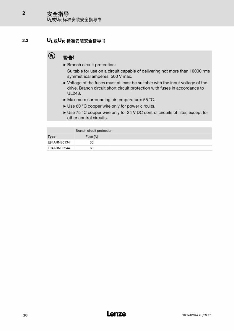
2.3 UL}UR �����/��
� uv!
ƒ Branch circuit protection:
Suitable for use on a circuit capable of delivering not more than 10000 rms
symmetrical amperes, 500 V max.
ƒ Voltage of the fuses must at least be suitable with the input voltage of the
drive. Branch circuit short circuit protection with fuses in accordance to
UL248.
ƒ Maximum surrounding air temperature: 55 °C.
ƒ Use 60 °C copper wire only for power circuits.
ƒ Use 75 °C copper wire only for 24 V DC control circuits of filter, except for
other control circuits.
Branch circuit protection
Type Fuse [A]
E94ARNE0134 30
E94ARNE0244 60
0123 �G@9�WX
3
� 11EDK94ARN24 ZH/EN 2.1
3 0123
3.1 ¡S23¢RL£¤
P¥6wx
T~
CE 2006/95/EG � ���
CM
UL UL 508C ��+n
!K��B�>@�n 132659
�j23
�WÀ �0«�++ 100% 7 3�����TNmTT � IT��¿8���3$]�|N��� IT ����y�
IT �� 100% 7
opM� EN 61800−3 � E94AZMR0xx4SDB ����n6 x 10 m�C2
� E94AZMR0xx4LDB ����n10 x 50 m�C2
À�nnÁ C3
ÁoÂ{ ��� EN 61800−3�
6  (ESD) EN 61000−4−2 ¯� _ 8 kV�
�Ã0¥Â _ 4 kV
�Ä
[q� EN 61000−4−6 150 kHz ... 80 MHz, 10 V/m 80% AM (1kHz)
¡���Ã� EN 61000−4−3 80 MHz ... 1000 MHz, 10 V/m 80% AM (1kHz)
d¦6����
}�ÃÄ EN 60529 IP 20 #" ZÅ.���Å~Ær2NEMA 250 12nÁ 1 �0¥4�
¡c ( EN 61800−5−1 � �nÁ III
"ÇHÆ» 2000 m :#\.Ç�n� �nÁ II
�� ¾o£ EN 61800−5−1 �ÈU/ÈÉ¡c���� �o£"
ɾʰÉ{ EN 61800−5−1 ';<�80n�ɾ4�
�9 (80n��ʰ
��80n��ʰ
 ; EN 61800−5−1 > 3.5 mA ]�T*������
sW �¿Ê ��_1"Ë-�2L ���ËËsW¿Ê"

0123 �G@9�WX
3
� 12 EDK94ARN24 ZH/EN 2.1
��§¨
�«+ ��Ì2
�ÌB Í'
�ÎÍ
\/�ÎÍ � 80 mm / � 120 mm ]�@#�xE��:X"ÎÅÎÍ |=��#�ÎÍ"
����� 5�§¨
Ï; �' "k-«� ����¢80
';<�' �.�&<=��'080
ab�1�)�.@ÏÐ+�e';<�' gtÑ"
£¤§¨
�£
4 IEC/EN 60721−3−1 1K3 (−25 ... +60 °C)
9� IEC/EN 60721−3−2 2K3 (−25 ... +70 °C)
9� IEC/EN 60721−3−3 3K3 (−10 ... +55 °C)
+45 ... +55 °C . ; *^�Çn2.5 %/°C
ÐÒÆ» ÇHÆ» 0 ... 4000 m
ÇHÆ» 1000 ... 4000 mn ; *^�Ç 5 %/1000 m
±² EN 61800−5−1 ±²ÃÄ 2
Áu7 (9.81 m/s2 = 1 g)
9� IEC/EN 60721−3−2 2M2
EN 61800−2 2 ... 9 HznuÓ 3.5 mm
10 ... 200 HznÁÈ*{7)�Ô 10 m/s2
200 ... 500 HznÁÈ*{7)�Ô 15 m/s2
9� Õ�ÑÖÕ×ÄÒ 5 ... 13.2 HznuÓ ±1 mm
13.2 ... 100 HznÁÈ*{7)�Ô 0.7 g
IEC/EN 60068−2−6 10 ... 57 HznuÓ 0.075 mm
57 ... 150 HznÁÈ*{7)�Ô 1 g
0123 ��G
3
� 13EDK94ARN24 ZH/EN 2.1
3.2 �©23
23ª«
�j �a �a¥¬ ®¥¬
ULN [V] ULN [V] f [Hz]
3/PE AC 230 180 − 0 % ... 264 + 0 % 45 − 0 % ... 65 + 0 %
3/PE AC 400 320 − 0 % ... 440 + 0 % 45 − 0 % ... 65 + 0 %
3/PE AC 500 400 − 0 % ... 550 + 0 % 45 − 0 % ... 65 + 0 %
�¯23°�±²
�a ® �" [A] ³2
[V] [Hz] v� +45 °C � v� +55 °C �
E94ARNE0134
9�À� 230/400/500 50/60 26/26/26 19.5/19.5/19.5 3
M �À� 230/400/500 50/60 13/13/13 9.8/9.8/9.8 3
E94ARNE0244
9�À� 230/400/500 50/60 47/47/47 35/35/35 3
M �À� 230/400/500 50/60 23.5/23.5/23.5 17.6/17.6/17.6 3
� Temperature in the control cabinet
� 8m��ØÓ
´� [V] SL [kVA]
E94ARNE0134
9�À� 230/400/500 10.3/18.0/22.5
M �À� 230/400/500 5.2/9.0/11.2
E94ARNE0244
9�À� 230/400/500 18.7/32.5/40.7
M �À� 230/400/500 9.4/16.3/20.3

0123 ��G
3
� 14 EDK94ARN24 ZH/EN 2.1
��23°µ"±²
�a ® �" [A] ³2
[V] [Hz] v� +45 °C � v� +55 °C �
E94ARNE0134
9�À� 325/565/705 0 (DC) 32/32/32 24/24/24 2
M �À� 345/586/727 0 (DC) 16/16/16 12/12/12 2
E94ARNE0244
9�À� 325/565/705 0 (DC) 57/57/57 43/43/43 2
M �À� 345/586/727 0 (DC) 28.5/28.5/28.5 21.4/21.4/21.4 2
� Temperature in the control cabinet
� ��ØÓ X109, X110, +UG, −UG
´� [V] � ���� PaDC [kW]
E94ARNE0134
9�À� 325/565/705 8.6/15/18.6
M �À� 345/586/727 4.3/7.5/9.3
E94ARNE0244
9�À� 325/565/705 15.6/27/33.8
M �À� 345/586/727 7.8/13.5/16.9
ØÓ}Ù PV [W]
´� �k�# IaN 9�.� Ú*�p���� �B�
E94ARNE0134 150 40
E94ARNE0244 230 40
-¶·¸¹º»¼V23
´� �9 ((v� −10%)
Û^ ;(0.5 s)
Û^�9ØÓ
(0.5 s)
8m ; 8m�9ØÓ
� [V]
AC DC RBR [�] IBRmax [A] PBRmax [kW] IBRd [A] PBRd [kW]
E94ARNE0134
230 345 18.0 19.2 6.6 9.4 1.6
400 586 27.0 21.7 12.7 10.6 3.0
500 727 27.0 26.9 19.6 13.2 4.7
E94ARNE0244
230 345 9.0 38.3 13.2 21.7 4.2
400 586 18.0 32.6 19.1 18.4 6.1
500 727 18.0 40.4 29.4 22.9 9.4

0123Z��� [Y@
3
� 15EDK94ARN24 ZH/EN 2.1
½����¾¿Àº»
�jÀº» ����� ��´�
��#� �¼·
E94AZMR0264SDB
E94AZMR0264LDBE94ARNE0134
E94AZPP0364 GG3E94AZMR0474SDB
E94AZMR0474LDBE94ARNE0244
E94AZMR0xxSDB −> "short distance" E94AZMR0xxLDB −> "long distance"
3.3 Á»6�ÃÄÅ
Operation with external mains choke/mains filter
Type Installation according to EN 60204−1 1) Installation according
to UL 2)FI 3)
� � L1, L2, L3 − Laying system � L1, L2, L3
B2 C F
[A] [A] [mm2] [mm2] [mm2] [A] [AWG] [mA]
E94AZMR0264x
DB
E94ARNE0134
C32
−
10
6 −
30 10 −
E94AZMR0474x
DB
E94ARNE0244
−
80
25
16 −
60 6 −
1) �+�Ñ_ÔÜ�G"e -��#k/Ý��������G VDE 0298−4�" [Y@�#�k@n-
PVC¡cÕ [m���{ < 70 °C�ÐÒ�{ < 45 °C� [&[w�ÞÖ�Fw"2) p - UL CM [�3$-Z���Z×ß"
UL Z��n � 500 ... 600 V3) ;¥¦Ø �¾�
��-b #�&à{�� 50 m � [�8�¾� )R�G [nP��EÄÓx�y�"
� �¾�
� -nÁ_ gG/gL �Z��&-nÁ_ gRL �á�ÙZ��
� Z��
12���«D�T
0123ZA�G
3
� 16 EDK94ARN24 ZH/EN 2.1
3.4 ÆÇ23
����°���4(²
SSP94GGmSo000
����� a
��#� �¼· [mm] [kg]
E94ARNE0134
E94ARNE0244E94AZPP0364 120 8.1

��4(5��678 4
� 17EDK94ARN24 ZH/EN 2.1
4 ��4(5��678
� TU!
#�3$��/K�"Ú2(����Ì)"
����0�"�������+�z�tu"
������5
� 18 EDK94ARN24 ZH/EN 2.1
5 ������
�P�:
1. ã���ºr�â·\�#/Û��'r¦Ür�(�_{"
2. �ä�â·\�����'rÝrÞ<Â��\ßä>lßäÌB"
3. ßä>�l���,����ÔrßäÌB�l?���Aßä"
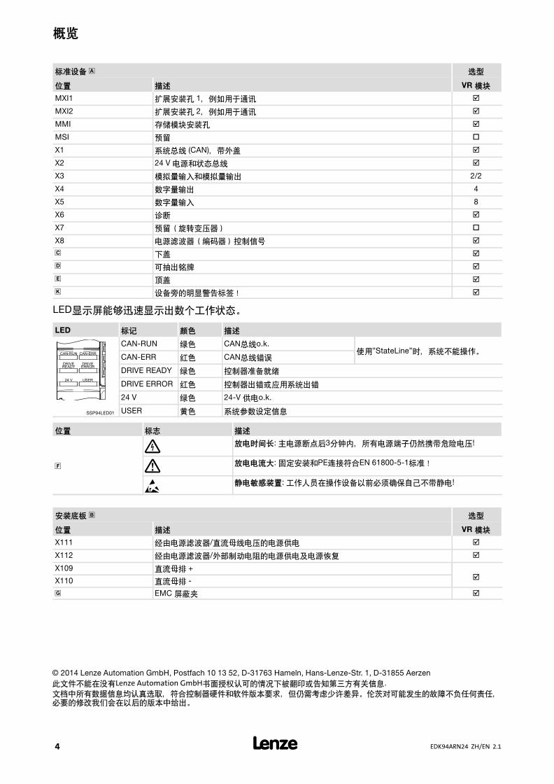
SSP94GG102
p 5−1 ����
�P\����:
1. �����8�0à"
2. á�Ôßä>â�����-�㣥+"
3. ã�������â·\I��ßä>\´ßäÌB"

97���� 6
� 19EDK94ARN24 ZH/EN 2.1
6 97����
XY!
È>�ÉXY5�a
� , 3 -�2�3�� �0�.�4��¸�Pä67� �"
Ê�ËÌ5;Í�
ƒå¥ �0�.�.z{&U|"
��ÎÏ�
ƒ" �0�.�\�K��¿� ��ÃålN 3 -�"
ƒæ®h©3�� �0�.�\k� �"
� kl!
#�+" )A6 }§�8@!
æ9#�����9!3$:4kqI�y-%�#�6 "
���
ƒ [3$12�«xE��/K(�, UL)"
ƒ (= [��67�Ôr#�/K:
–�(=¥+@ç��(=0³.
–D)-�|(=�èç&èèÕ×�|(=�(=(Á�.
–�|(=�UéÓ> 70 %�Uéê_90°.
–�(= [}É}ë.
-�� [&(= [80:
ƒ �����������
ƒ CAN ����
ƒ �����
ƒ ��m\80
#�80�$(=:
ƒ 24 V '
ƒ ����(�����)
� 0J!
- L−force Engineer J@i��)�#*�«B"E�J@�-��)L"�ì~�J@ÏÐ"

97����6
� 20 EDK94ARN24 ZH/EN 2.1
yzÐ8CAN7Ñ
ҩX1 �� ��
Pin 2 CAN−LOW
Pin 3 CAN−GND
Pin 7 CAN−HIGH
9400SSP000X1 (�Ã) CAN−Shield
24 V �
ҩX2 �� ��
GE GND �8'
24E 24 V �8' , ���-£À' (SELV/PELV)
9400SSP000X2 SB ����in/out ()LGE)
Ò©23
�8ÄÅ ÓÔÕÖ
[mm2] [AWG] [Nm] [lb−in]
é70.2 ... 2.5 24 ... 12 íî.�
�0�.êë
�×�¯, �×��
ҩX3 �� ��
GA GND ����
AO1 �����1
AO2 �����2
A1+ �����1 +
A1− �����1 −
A1− �����1 −
A1R �. ( ï20mA
A2+ �����2 +
A2− �����2 −
SSP94000X3 � (=80: "EMC0�.�(=
Ò©23
�8ÄÅ ÓÔÕÖ
[mm2] [AWG] [Nm] [lb−in]
é70.2 ... 2.5 24 ... 12 íî.�
�0�.êë
97���� 6
� 21EDK94ARN24 ZH/EN 2.1
2��
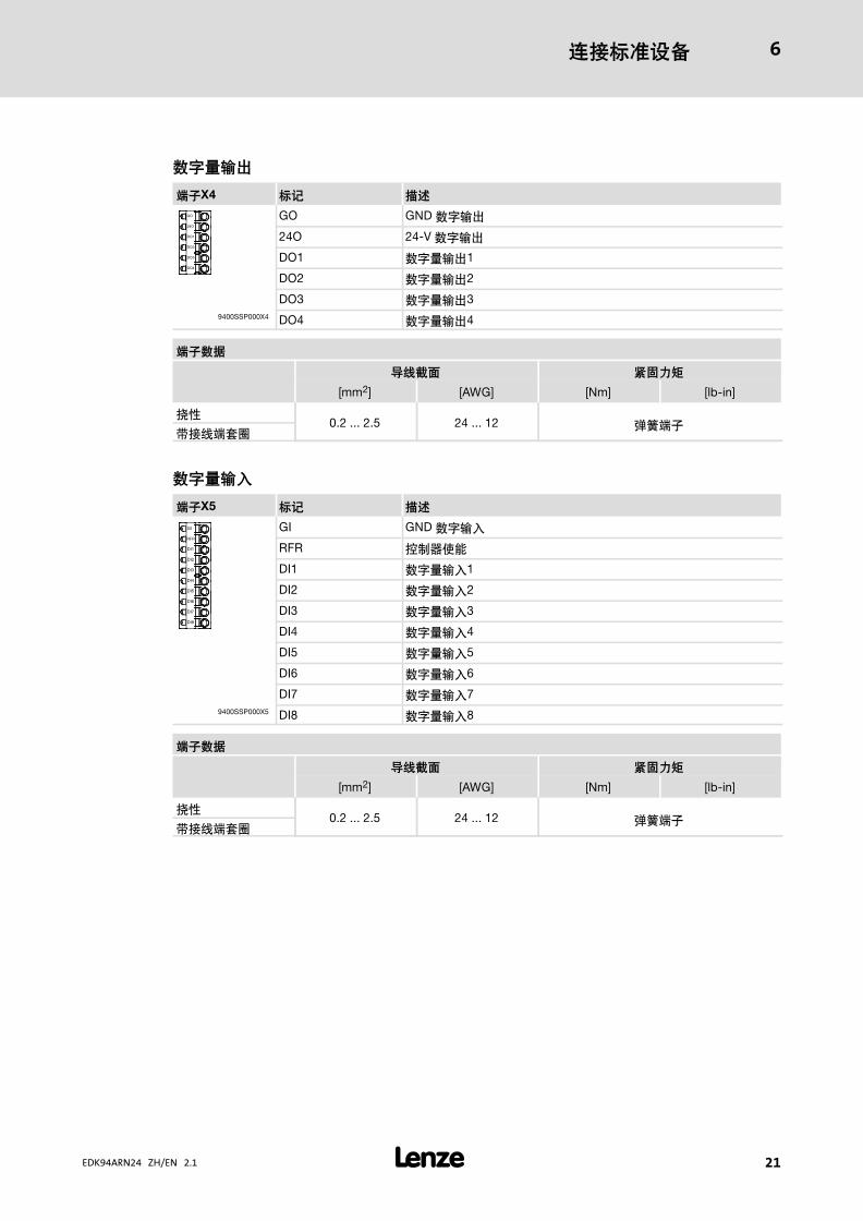
ҩX4 �� ��
GO GND ����
24O 24−V ����
DO1 �����1
DO2 �����2
DO3 �����3
9400SSP000X4 DO4 �����4
Ò©23
�8ÄÅ ÓÔÕÖ
[mm2] [AWG] [Nm] [lb−in]
é70.2 ... 2.5 24 ... 12 íî.�
�0�.êë
2Ø�¯
ҩX5 �� ��
GI GND ����
RFR ���-)
DI1 �����1
DI2 �����2
DI3 �����3
DI4 �����4
DI5 �����5
DI6 �����6
DI7 �����7
9400SSP000X5 DI8 �����8
Ò©23
�8ÄÅ ÓÔÕÖ
[mm2] [AWG] [Nm] [lb−in]
é70.2 ... 2.5 24 ... 12 íî.�
�0�.êë
97����6
� 22 EDK94ARN24 ZH/EN 2.1
ÙÂ/ÚÛÜ
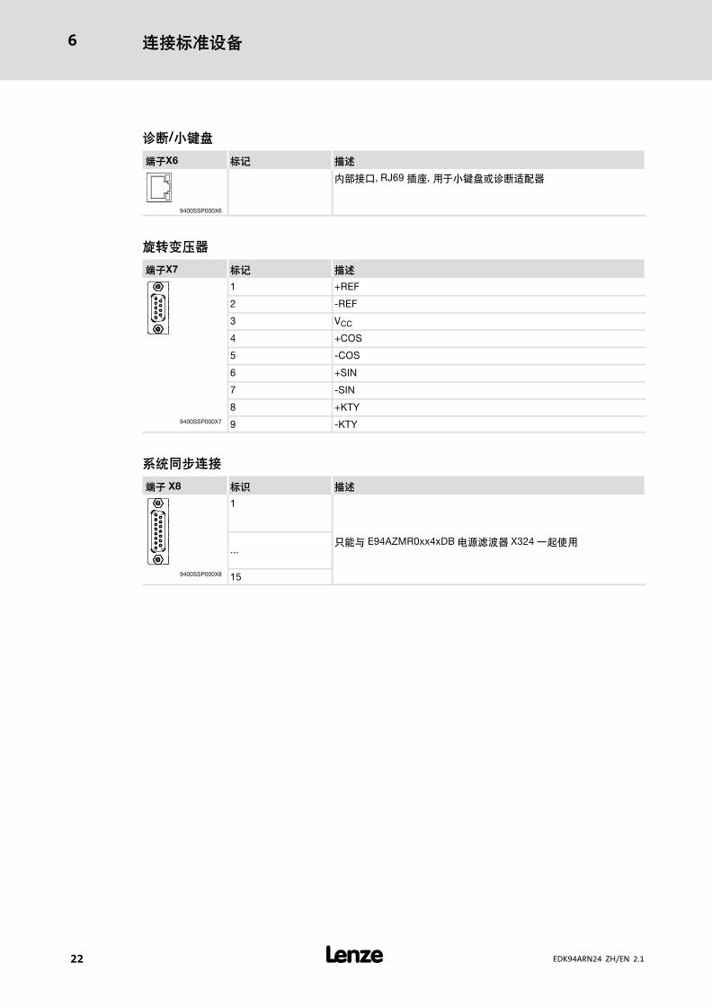
ҩX6 �� ��
280³, RJ69 º�, �Rðì&���«�
9400SSP000X6
ÝÞßa»
ҩX7 �� ��
1 +REF
2 −REF
3 VCC
4 +COS
5 −COS
6 +SIN
7 −SIN
8 +KTY
9400SSP000X7 9 −KTY
yzàá97
Ò© X8 �â ��
1
D)@ E94AZMR0xx4xDB ���� X324 <í-...
9400SSP000X8 15
97� ���
7
� 23EDK94ARN24 ZH/EN 2.1
7 97�
���-�I��#�P�����WX�#�Lñ ����sòÉóî�z��1)uxE����"
7.1 ¡ã�
-���ºô � MXI1 & �MXI2 �MMI �MSI.
äåæ
E94YCEN001A
p 7−1 E94AYCEN ���(#ïð)
97
�� ��
X215 #ïð80-PnRJ45 º���G IEC 60603−7�
X216 #ïð80-PnRJ45 º���G IEC 60603−7�
ç[
�� �� èé ��
MS +, õ� ���¸� �"
DE $, õ� ��#�#0° ����)���#�>F+�:X�
X215/X216 97AG���
− (, õ�/ñò n �#ïðÏÊ�G"
− +, õ� #ïð80 "

97� ���
7
� 24 EDK94ARN24 ZH/EN 2.1
CANopen
E94YCCA001B
p 7−2 E94AYCCA ���(CANopen)
97
�� ��
X220 CAN��80
WÀ: Sub−D80ºà, 9−�
X220 �� ��
Pin 2 CAN−LOW
Pin 3 CAN−GND
Pin 7 CAN−HIGH
9400SSP000X1 (�Ã) CAN−Shield

97� ���
7
� 25EDK94ARN24 ZH/EN 2.1
DIP êë
�� ��
� ��Ñ+��
Baud CAN Address
ON cd b a 64 32 16 8 4 2 1A
9400CAN003
p 7−3 DIPö��E�=j��ó
�"�8�DIPö��E��
ƒ Ñ+«� (�y_ "1" ... "64") �
ƒ �ôÓ (�y_ "a" ... "d")
H #B"
� TU!
õ�÷#�"õ�.3�«��EH¢�"OFF" ÌB�8���«BC00350 (Ñ+«�)�C00351 (�ôÓ) "
E¯�÷#� �,Uæ#øùaQ#B"
��ìíîï
�9Ñ+«�&3�¢�eONgÌB�«��E��köji"
��ºr®
d c b A ºr®
OFF ON ON OFF 10kbit/s
OFF ON OFF ON 20kbit/s
OFF OFF ON ON 50kbit/s
OFF OFF ON OFF 125kBit/s
OFF OFF OFF ON 250kbit/s
OFF OFF OFF OFF 500kbit/s
ON ON ON OFF 800kbit/s
OFF ON OFF OFF 1000kbit/s
OFF ON ON ON %9�ôÓ
ç[
�� �� èé ��
MS +, ÷ ���� "
DE $, ÷ ���#A���óÁ (zu�������).
BS +, �GDR303−3��M��
CANopen �� ("Z")
BE $, CANopen %/ ("F")
97� ���
7
� 26 EDK94ARN24 ZH/EN 2.1
PROFIBUS
E94YCPM001A
p 7−4 E94AYCPM ���(PROFIBUS)
97
�� ��
X200 ����8' WÀ: ø�80ºà, 2−ú
X201 PROFIBUS80
WÀ: Sub−Dº�, 9−ú
X200 �� ��
+-
24 V �8' , ���-£À' (SELV/PELV)
+ 24�V�DC
20.4 − 0�% ... 28.8 V�+ 0�%, v�200 mA
SSP94KP200
− GND
)L Ì
ð^ ñ òó TU
1
2
3
4
5
6
7
8
9
1 ¯ù −
2 ¯ù −
3 RxD/TxD−P �G� B�0°�G/Mú�G�n���
4 RTS �KMú�0°�G/Mú�G��û-���
5 M5V2 �G0«�5 V 0«�
6 P5V2 5 V DC / 30 mA �<��.�
7 ¯ù −
8 RxD/TxD−N �G� A�0°�G/Mú�G�O���
9 ¯ù −
97� ���
7
� 27EDK94ARN24 ZH/EN 2.1
DIP êë
�� ��
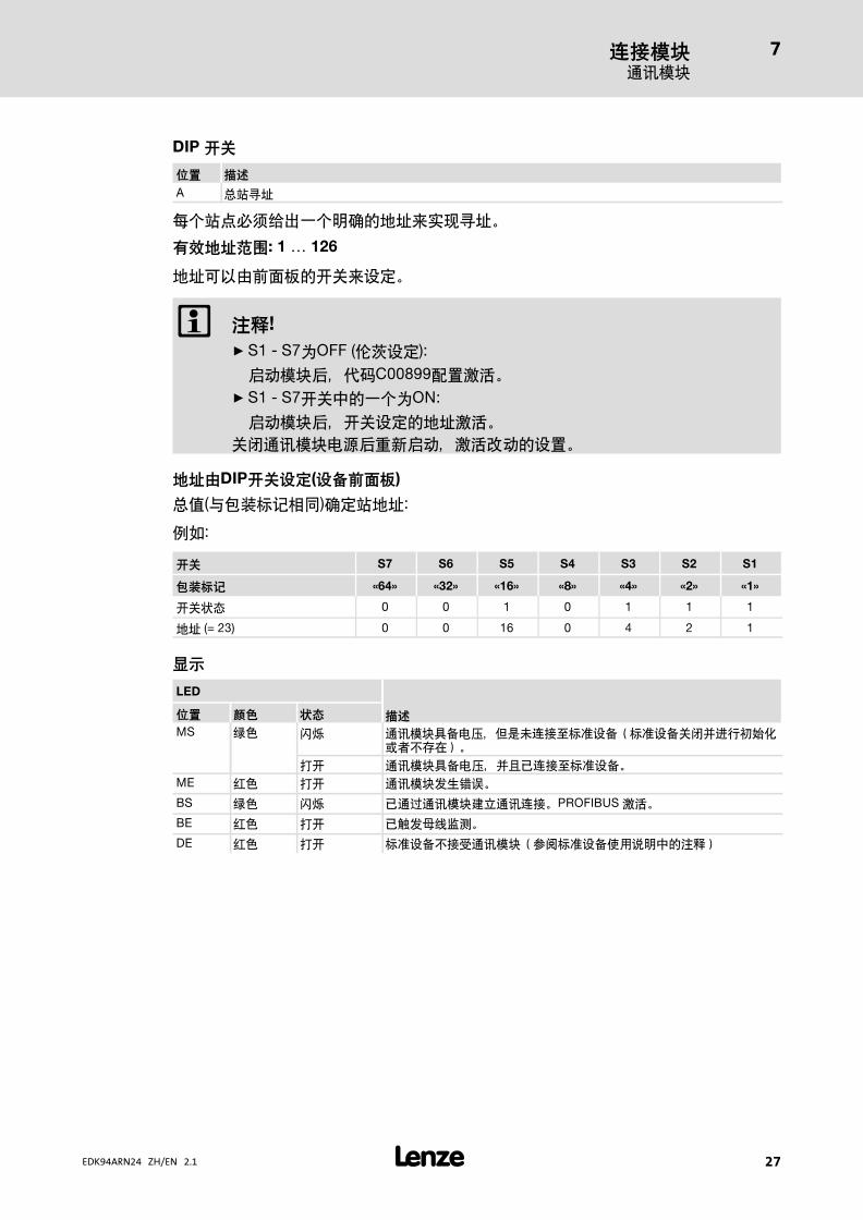
A ����
ü �+3$S�< �:�«�i�Ð��"
>?î塞: 1 126
«� #&�@·��Ei#*"
� TU!
ƒ S1 − S7_OFF (OK#*):
æ9��,�û�C00899«Bøù"
ƒ S1 − S7�E+�< _ON:
æ9��,��E#*�«�øù"
E¯ ��� �,UEæ9�øùQ9�#B"
îïôDIPêë�V(��õÅ()
�^(@��yxm):*�«�:
��:
êë S7 S6 S5 S4 S3 S2 S1
ö��� «64» «32» «16» «8» «4» «2» «1»
�E�� 0 0 1 0 1 1 1
«� (= 23) 0 0 16 0 4 2 1
ç[
LED
���� �� èé
MS +, ñò ���¸� ��Ih�80l��#����#�E¯|��[�ü&j#"�"
õ� ���¸� ��|dk80l��#�"
ME $, õ� ���MP%/"
BS +, ñò k � ���ý �80"PROFIBUS øù"
BE $, õ� k¥M<�¬"
DE $, õ� ��#�#0° ����)���#�-��+�:X�
97� ��
7
� 28 EDK94ARN24 ZH/EN 2.1
7.2 b÷�
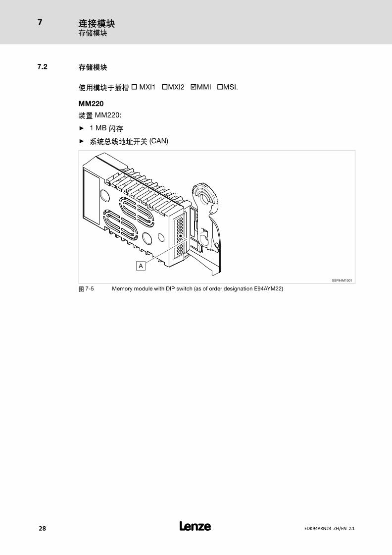
-���ºô � MXI1 �MXI2 �MMI �MSI.
MM220
B MM220:
ƒ 1 MB ñ
ƒ ����«��E (CAN)
SSP94M1001
p 7−5 Memory module with DIP switch (as of order designation E94AYM22)

97� ����
7
� 29EDK94ARN24 ZH/EN 2.1
Baud CAN Address
ON cd b a 64 32 16 8 4 2 1A
9400CAN003
p 7−6 DIPö��E�=j��ó
�"�8�DIPö��E��
ƒ Ñ+«� (�y_ "1" ... "64") �
ƒ �ôÓ (�y_ "a" ... "d")
H #B"
� TU!
õ�÷#�"õ�.3�«��EH¢�"OFF" ÌB�8���«BC00350 (Ñ+«�)�C00351 (�ôÓ) "
E¯�÷#� �,Uæ#øùaQ#B"
��ìíîï
�9Ñ+«�&3�¢�eONgÌB�«��E��köji"
��ºr®
d c b A ºr®
OFF ON ON OFF 10kbit/s
OFF ON OFF ON 20kbit/s
OFF OFF ON ON 50kbit/s
OFF OFF ON OFF 125kBit/s
OFF OFF OFF ON 250kbit/s
OFF OFF OFF OFF 500kbit/s
ON ON ON OFF 800kbit/s
OFF ON OFF OFF 1000kbit/s
OFF ON ON ON %9�ôÓ
7.3 �/�
��-CP)�' ���8��Ø)ø "Ih�MSI +� SM0 ��_É�7
/K�#�9�CP)�' ��"

:;<=" 400 V � �\��[\]]
8
� 30 EDK94ARN24 ZH/EN 2.1
8 :;<=
8.1 c 400 V �j�aùKLúáûü
�G������,�CP)�' ��� " 400 V � �\9�"
_?� ������ RFR øùCPþý"
�PN�n
1. õ� 24 V � �"
–� ����
–�CP)�' ��� -�
2. õ� 400 V � �"
3. ������ RFR øù/�CPþý"
8.2 c 230 } 500 V �j�aùKLúáûü
þ�0/#BCP)�' ���28 � ��#�" 230 V & 500 V � �\9
�"#B" C00173 +��� ���@·&OK PC J@ »Engineer« ��"
]]30k@n
ƒ < EZAEBKx00x ��@·
&
ƒ � Windows� ���� (XP & 2000) �köZ
ƒ OK PC J@ »Engineer«
ƒ �0³80CP)�' �����
–� USB ���«����0³ X6
– CAN ����
–º��� M1/M2 � ���
ƒ 3-�le��xEJ@ÏÐ
ƒ %9üÇ�ð�� �ÏÐ
ƒ õ� 24 V � �"
–� ����
–�CP)�' ��
�G � ���#B,n
1. õ� � �"
2. ������ RFR øù/�CPþý"

:;<=�<\#B
8
� 31EDK94ARN24 ZH/EN 2.1
8.3 Kh�
]�J@��|/&��CP)�' ��)�ü#B>F"

� 32 EDK94ARN24 ZH/EN 2.1
Overview
Standard device � Design
Pos. Description VR module
MXI1 Expansion slot 1, e.g. for communication �
MXI2 Expansion slot 2, e.g. for communication �
MMI Storage module slot �
MSI Reserved �
X1 System bus (CAN), under the cover �
X2 24 V supply and statebus �
X3 Analog inputs and analog outputs 2/2
X4 Digital outputs 4
X5 Digital inputs 8
X6 Diagnostics �
X7 Reserved (resolver) �
X8 Control signals for mains filter (encoder) �
� Lower cover �
� Retractable nameplate �
� Upper cover �
� Prominent warning label close to the device! �
The LED display enables fast indication of several operating states.
LED Labelling Colour Description
CAN−RUN green CAN bus o.k. Inoperable when "StateLine" design isusedCAN−ERR red CAN bus error
DRIVE READY green Standard device is ready for operation
DRIVE ERROR red Error in the standard device or due to the application
24 V green 24−V supply voltage o.k.
SSP94LED01 USER yellow Message parameterised by the application
Pos. Symbol Description
Long discharge time: All power terminals carry hazardous voltages for atleast 3 minutes after mains disconnection!
� High discharge current: Fixed installation and PE connection to EN 61800−5−1required!
� Electrostatic sensitive devices: Before working on the device, personnel mustensure that they are free of electrostatic charge!
Installation backplane Design
Pos. Description VR module
X111 Mains supply via mains filter/DC−bus voltage �
X112 Mains supply and mains power recovery via mains filter/external brake resistor �
X109 DC busbar +�X110 DC busbar −
� EMC shield clamp �
© 2014 Lenze Automation GmbH, Postfach 10 13 52, D−31763 Hameln, Hans−Lenze−Str. 1, D−31855 AerzenNo part of this documentation may be reproduced or made accessible to third parties without written consent by Lenze Automa-tion GmbH.All information given in this documentation has been selected carefully and complies with the hardware and software described.Nevertheless, discrepancies cannot be ruled out. We do not take any responsibility or liability for any damage that may occur. Ne-cessary corrections will be included in subsequent editions.

Contents i
� 33EDK94ARN24 ZH/EN 2.1
1 About this documentation 34
1.1 Validity information 34
1.2 Document history 34
1.3 Target group 34
1.4 Conventions used 34
1.5 Notes used 35
2 Safety instructions 36
2.1 General safety and application notes for Lenze power supply modules 36
2.2 Residual hazards 38
2.3 Safety instructions for the installation according to UL oder UR 39
3 Technical data 40
3.1 General data and operating conditions 40
3.2 Electrical data 42
3.3 Fuses and cable cross−sections 44
3.4 Mechanical data 45
4 Mounting and wiring the installation backplane 46
5 Mounting the standard device 47
6 Wiring of the standard device 48
7 Wiring the device modules 52
7.1 Communication modules 52
7.2 Memory modules 58
7.3 Safety modules 59
8 Final works 60
8.1 Initial commissioning at a mains voltage of 400 V 60
8.2 Initial commissioning at a mains voltage of 230 or 500 V 60
8.3 Further settings 61

About this documentationValidity information
1
� 34 EDK94ARN24 ZH/EN 2.1
0Fig. 0Tab. 0
1 About this documentation
1.1 Validity information
These instructions are valid for
ƒ E94ARNE0134 and E94ARNE0244 regenerative power supply modules.
These mounting instructions are only valid in conjunction with the documentation on the
ƒ E94AZMR0xx4xDB mains filter (� EDK94ZMR47XDB).
1.2 Document history
Material number Version Description
13240129 1.0 03/2008 TD15 First edition
.P#T 2.1 08/2014 TD29 Revision
� Tip!
Documentation and software updates for further Lenze products can be foundon the Internet in the "Services & Downloads" area under
http://www.Lenze.com
1.3 Target group
This documentation is intended for qualified personnel according to IEC 364.
Qualified, skilled personnel are persons who have the qualifications necessary for the workactivities to be undertaken during the assembly, installation, comissioning, and operationof the product.
1.4 Conventions used
This documentation uses the following conventions to distinguish between differenttypes of information:
Spelling of numbers
Decimal separator Point In general, the decimal point is used.For instance: 1234.56
Warnings
UL warnings �Are only given in English.
UR warnings �
Icons
Page reference � Reference to another page with additionalinformationFor instance: � 16 = see page 16

About this documentationNotes used
1
� 35EDK94ARN24 ZH/EN 2.1
1.5 Notes used
The following pictographs and signal words are used in this documentation to indicatedangers and important information:
Safety instructions
Structure of safety instructions:
� Danger!
(characterises the type and severity of danger)
Note
(describes the danger and gives information about how to prevent dangeroussituations)
Pictograph and signal word Meaning
Danger!
Danger of personal injury through dangerous electrical voltage.Reference to an imminent danger that may result in death orserious personal injury if the corresponding measures are nottaken.
� Danger!
Danger of personal injury through a general source of danger.Reference to an imminent danger that may result in death orserious personal injury if the corresponding measures are nottaken.
� Stop!Danger of property damage.Reference to a possible danger that may result in propertydamage if the corresponding measures are not taken.
Application notes
Pictograph and signal word Meaning
� Note! Important note to ensure troublefree operation
� Tip! Useful tip for simple handling
� Reference to another documentation
Special safety instructions and application notes for UL and UR
Pictograph and signal word Meaning
� Warnings!
Safety or application note for the operation of a UL−approveddevice in UL−approved systems.Possibly the drive system is not operated in compliance with ULif the corresponding measures are not taken.
� Warnings!
Safety or application note for the operation of a UR−approveddevice in UL−approved systems.Possibly the drive system is not operated in compliance with ULif the corresponding measures are not taken.

Safety instructionsGeneral safety and application notes for Lenze power supply modules
2
� 36 EDK94ARN24 ZH/EN 2.1
2 Safety instructions
2.1 General safety and application notes for Lenze power supply modules
(According to: Low−Voltage Directive 2006/95/EC)
General
Lenze power supply modules can include live and rotating parts ˘ depending on their typeof protection ˘ during operation. Surfaces can be hot.
Non−authorised removal of the required cover, inappropriate use, incorrect installation oroperation, create the risk of severe injury to persons or damage to material assets.
More information can be obtained from the documentation.
All operations concerning transport, installation, and commissioning as well asmaintenance must be carried out by qualified, skilled personnel (IEC 364/CENELEC HD 384or DIN VDE 0100 and IEC report 664 or DIN VDE 0110 and national regulations for theprevention of accidents must be observed).
According to this basic safety information qualified, skilled personnel are persons who arefamiliar with the assembly, installation, commissioning, and operation of the product andwho have the qualifications necessary for their occupation.
Application as directed
Power supply modules are components which are designed for installation in electricalsystems or machinery. They are not to be used as domestic appliances, but only forindustrial purposes according to EN 61000−3−2. The documentation contains informationabout compliance with the limit values according to EN 61000−3−2.
When installing the power supply modules into machines, commissioning (i.e. starting ofoperation as directed) is prohibited until it is proven that the machine corresponds to theregulations of the EC Directive 98/37/EC (Machinery Directive); EN 60204 must beobserved.
Commissioning (i.e. starting of operation as directed) is only allowed when there iscompliance with the EMC Directive (2004/108/EC).
The power supply modules meet the requirements of the Low−Voltage Directive2006/95/EC. The harmonised standards of the EN 61800−5−1 series apply to the powersupply modules.
The technical data and information on connection conditions can be obtained from thenameplate and the documentation. They must be strictly observed.
Warning: The power supply modules are products which are intended for use in anindustrial environment according to EN 61800−3. Operation on public mains suppliesrequires additional measures to be taken for limiting the expected radio interference.
Transport and storage
Please observe the notes on transport, storage and appropriate handling.
Observe the climatic conditions according to the technical data.
Safety instructionsGeneral safety and application notes for Lenze power supply modules
2
� 37EDK94ARN24 ZH/EN 2.1
Installation
The power supply modules must be installed and cooled according to the instructionsgiven in the corresponding documentation.
Ensure proper handling and avoid mechanical stress. Do not bend any components and donot change any insulation distances during transport or handling. Do not touch anyelectronic components and contacts.
Power supply modules contain electrostatically sensitive components, which can easily bedamaged by inappropriate handling. Do not damage or destroy any electrical componentssince this might endanger your health!
Electrical connection
When working on live power supply modules, the valid national regulations for theprevention of accidents (e.g. VBG 4) must be observed.
The electrical installation must be carried out according to the appropriate regulations(e.g. cable cross−sections, fuses, PE connection). Additional information can be obtainedfrom the documentation.
Notes about installation according to EMC regulations (shielding, earthing, filters andcable routing) are included in the documentation. These notes also apply to CE−markedpower supply modules. The compliance with limit values required by the EMC legislationis the responsibility of the manufacturer of the machine or system.
Operation
If necessary, systems including power supply modules must be equipped with additionalmonitoring and protection devices according to the valid safety regulations (e.g. law ontechnical equipment, regulations for the prevention of accidents). The power supplymodules can be adapted to your application. Please observe the correspondinginformation given in the documentation.
After a power supply module has been disconnected from the voltage supply, all livecomponents and power connections must not be touched immediately because capacitorscan still be charged. Please observe the corresponding stickers on the power supplymodule.
All protection covers and doors must be shut during operation.
Note for UL approved systems with integrated power supply modules: UL warnings arenotes that only apply to UL systems. The documentation contains special UL notes.
Maintenance and servicing
The power supply modules do not require any maintenance if the prescribed conditions ofoperation are observed.
If the ambient air is polluted, the cooling surfaces of the power supply module may becomedirty or the air vents of the power supply module may be obstructed. Therefore, clean thecooling surfaces and air vents periodically under these operating conditions. Do not usesharp or pointed tools for this purpose!
Safety instructionsResidual hazards
2
� 38 EDK94ARN24 ZH/EN 2.1
Disposal
Recycle metal and plastic materials. Ensure professional disposal of assembled PCBs.
The product−specific safety and application notes given in these instructions must beobserved!
2.2 Residual hazards
Protection of persons
ƒ Before working on the power supply module, check that all power terminals aredeenergised
– because the power terminals L1, L2, L3, +UG, −UG, Rb1, Rb2, X109 and X110 carryhazardous voltages for at least 3 minutes after mains disconnection.
– because the power terminals carry hazardous voltages even when only the mainsvoltage is applied.
Device protection
ƒ Connect/disconnect all pluggable terminals only in deenergised condition!
ƒ Detach the power supply modules from their installation backplanes only indeenergised condition!
ƒ The unit only functions properly when the 24 V supply is switched on!
Safety instructionsSafety instructions for the installation according to UL oder UR
2
� 39EDK94ARN24 ZH/EN 2.1
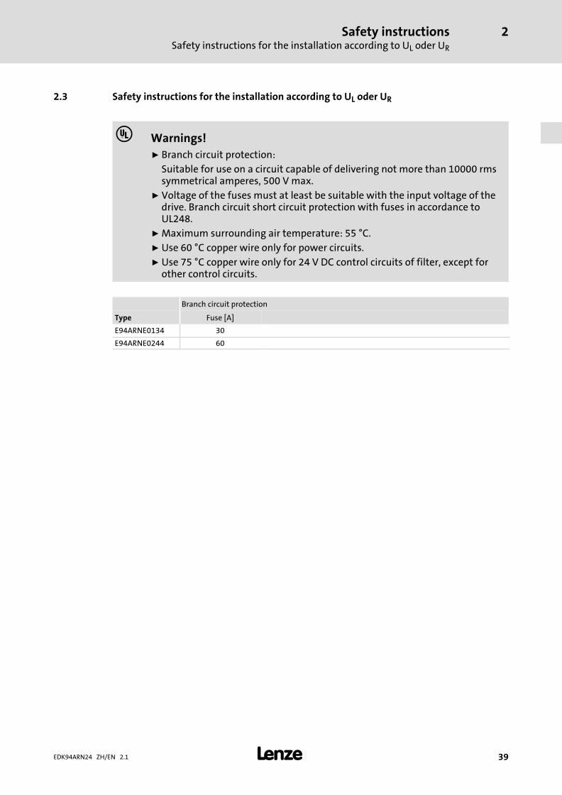
2.3 Safety instructions for the installation according to UL oder UR
� Warnings!
ƒ Branch circuit protection:
Suitable for use on a circuit capable of delivering not more than 10000 rmssymmetrical amperes, 500 V max.
ƒ Voltage of the fuses must at least be suitable with the input voltage of thedrive. Branch circuit short circuit protection with fuses in accordance toUL248.
ƒ Maximum surrounding air temperature: 55 °C.
ƒ Use 60 °C copper wire only for power circuits.
ƒ Use 75 °C copper wire only for 24 V DC control circuits of filter, except forother control circuits.
Branch circuit protection
Type Fuse [A]
E94ARNE0134 30
E94ARNE0244 60
Technical dataGeneral data and operating conditions
3
� 40 EDK94ARN24 ZH/EN 2.1
3 Technical data
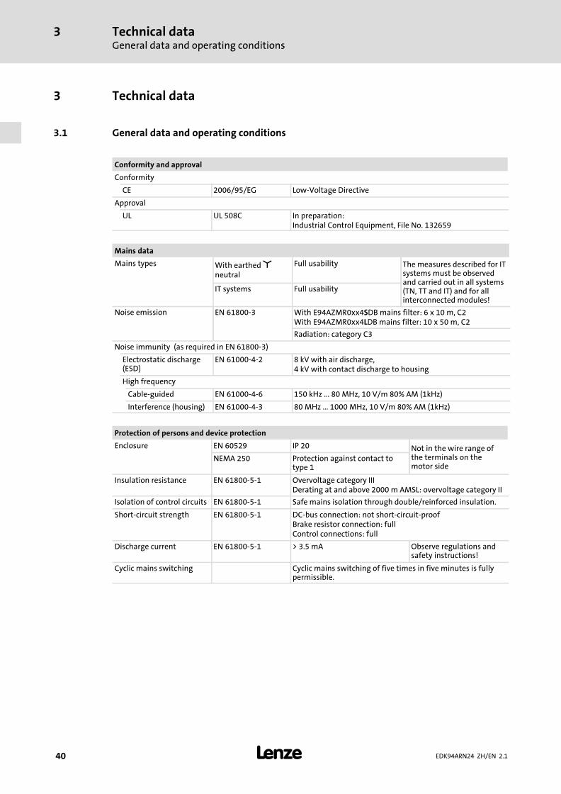
3.1 General data and operating conditions
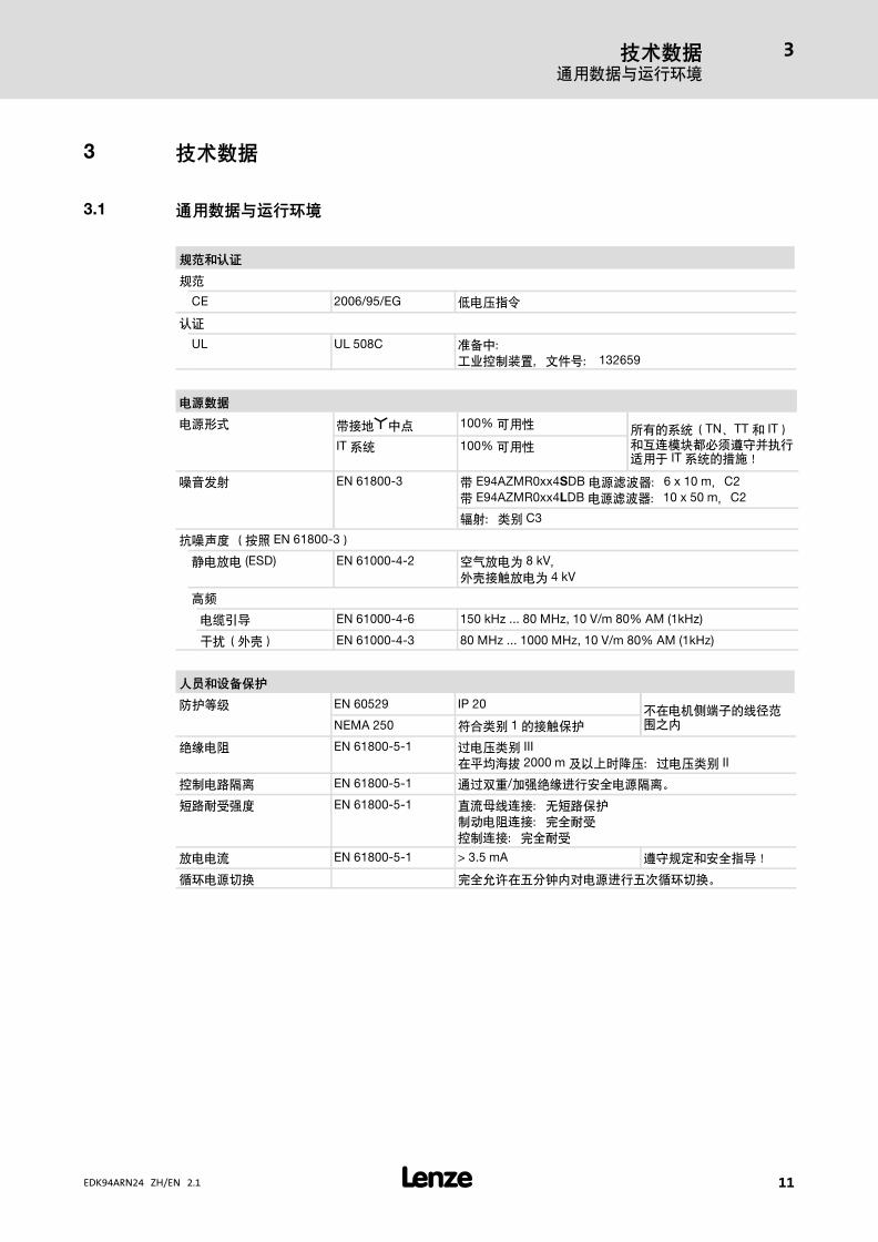
Conformity and approval
Conformity
CE 2006/95/EG Low−Voltage Directive
Approval
UL UL 508C In preparation:Industrial Control Equipment, File No. 132659
Mains data
Mains types With earthed �neutral
Full usability The measures described for ITsystems must be observedand carried out in all systems(TN, TT and IT) and for allinterconnected modules!
IT systems Full usability
Noise emission EN 61800−3 With E94AZMR0xx4SDB mains filter: 6 x 10 m, C2With E94AZMR0xx4LDB mains filter: 10 x 50 m, C2
Radiation: category C3
Noise immunity (as required in EN 61800−3)
Electrostatic discharge(ESD)
EN 61000−4−2 8 kV with air discharge,4 kV with contact discharge to housing
High frequency
Cable−guided EN 61000−4−6 150 kHz ... 80 MHz, 10 V/m 80% AM (1kHz)
Interference (housing) EN 61000−4−3 80 MHz ... 1000 MHz, 10 V/m 80% AM (1kHz)
Protection of persons and device protection
Enclosure EN 60529 IP 20 Not in the wire range ofthe terminals on themotor side
NEMA 250 Protection against contact totype 1
Insulation resistance EN 61800−5−1 Overvoltage category IIIDerating at and above 2000 m AMSL: overvoltage category II
Isolation of control circuits EN 61800−5−1 Safe mains isolation through double/reinforced insulation.
Short−circuit strength EN 61800−5−1 DC−bus connection: not short−circuit−proofBrake resistor connection: fullControl connections: full
Discharge current EN 61800−5−1 > 3.5 mA Observe regulations andsafety instructions!
Cyclic mains switching Cyclic mains switching of five times in five minutes is fullypermissible.

Technical dataGeneral data and operating conditions
3
� 41EDK94ARN24 ZH/EN 2.1
Mounting conditions
Mounting place In the control cabinet
Mounting position Vertical
Mounting clearances
Above/below � 80 mm / � 120 mmObserve the device−relatednotes on mounting.To the sides Side−by−side mounting without
any clearance
Supply conditions for the regenerative power supply module
AC mains operation Connection at the assigned mains filter
DC−bus operation Direct connection of the axis modules via terminals orbusbar systemsSee the chapter on DC−bus operation in the HardwareManual for further information.
Environmental conditions
Climate
Storage IEC/EN 60721−3−1 1K3 (−25 ... +60 °C)
Transport IEC/EN 60721−3−2 2K3 (−25 ... +70 °C)
Operation IEC/EN 60721−3−3 3K3 (−10 ... +55 °C)Current derating at +45 ... +55 °C: 2.5 %/°C
Site altitude 0 ... 4000 m amsl1000 ... 4000 m amsl: current derating of 5 %/1000 m
Pollution EN 61800−5−1 Pollution degree 2
Vibration resistance (9.81 m/s2 = 1 g)
Transport IEC/EN 60721−3−2 2M2
EN 61800−2 2 ... 9 Hz: amplitude 3.5 mm
10 ... 200 Hz: acceleration resistant up to 10 m/s2
200 ... 500 Hz: acceleration resistant up to 15 m/s2
Operation Germanischer Lloyd 5 ... 13.2 Hz: amplitude ±1 mm13.2 ... 100 Hz: acceleration resistant up to 0.7 g
IEC/EN 60068−2−6 10 ... 57 Hz: amplitude 0.075 mm
57 ... 150 Hz: acceleration resistant up to 1 g
Technical dataElectrical data
3
� 42 EDK94ARN24 ZH/EN 2.1
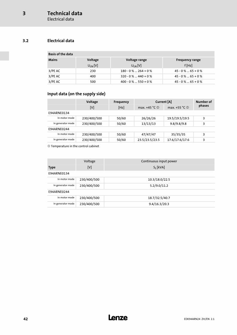
3.2 Electrical data
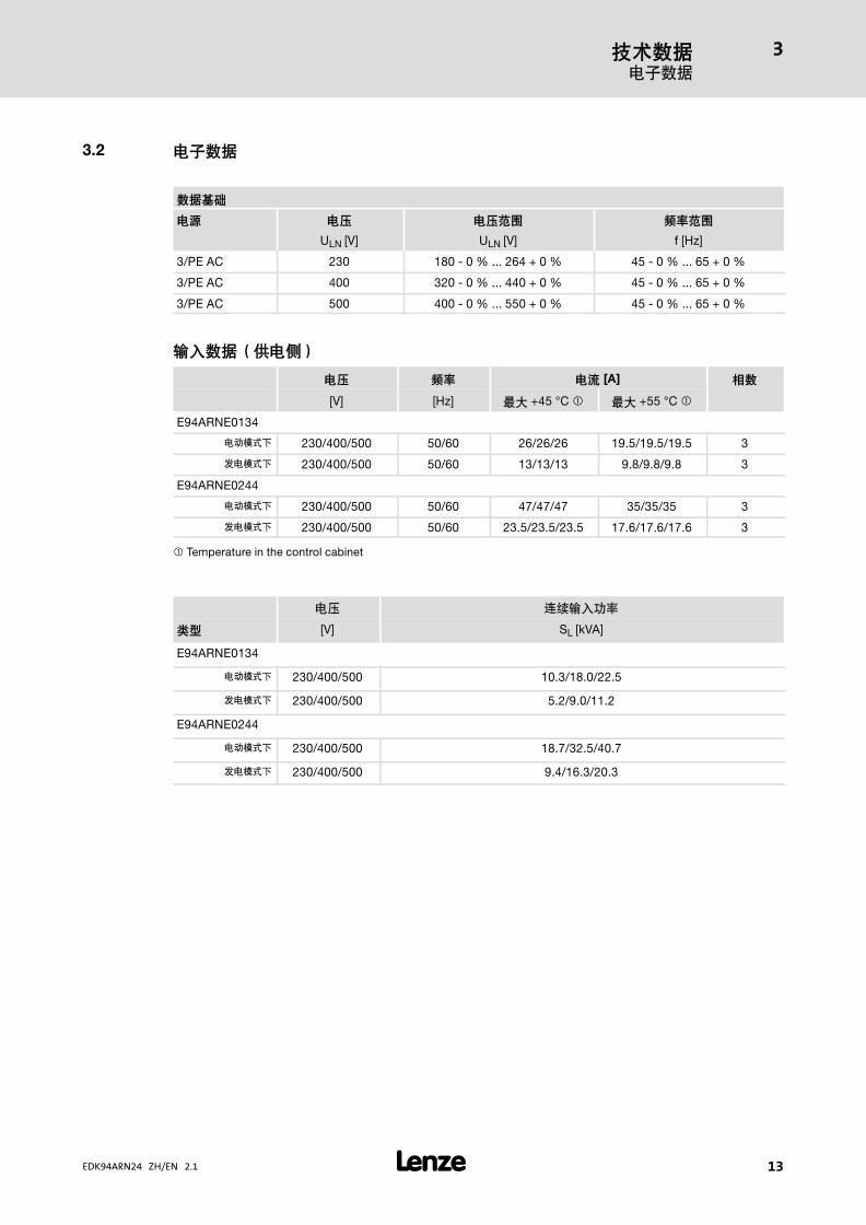
Basis of the data
Mains Voltage Voltage range Frequency range
ULN [V] ULN [V] f [Hz]
3/PE AC 230 180 − 0 % ... 264 + 0 % 45 − 0 % ... 65 + 0 %
3/PE AC 400 320 − 0 % ... 440 + 0 % 45 − 0 % ... 65 + 0 %
3/PE AC 500 400 − 0 % ... 550 + 0 % 45 − 0 % ... 65 + 0 %
Input data (on the supply side)
Voltage Frequency Current [A] Number ofphases
[V] [Hz] max. +45 °C � max. +55 °C �
E94ARNE0134
In motor mode 230/400/500 50/60 26/26/26 19.5/19.5/19.5 3
In generator mode 230/400/500 50/60 13/13/13 9.8/9.8/9.8 3
E94ARNE0244
In motor mode 230/400/500 50/60 47/47/47 35/35/35 3
In generator mode 230/400/500 50/60 23.5/23.5/23.5 17.6/17.6/17.6 3
� Temperature in the control cabinet
Voltage Continuous input power
Type [V] SL [kVA]
E94ARNE0134
In motor mode 230/400/500 10.3/18.0/22.5
In generator mode 230/400/500 5.2/9.0/11.2
E94ARNE0244
In motor mode 230/400/500 18.7/32.5/40.7
In generator mode 230/400/500 9.4/16.3/20.3
Technical dataElectrical data
3
� 43EDK94ARN24 ZH/EN 2.1
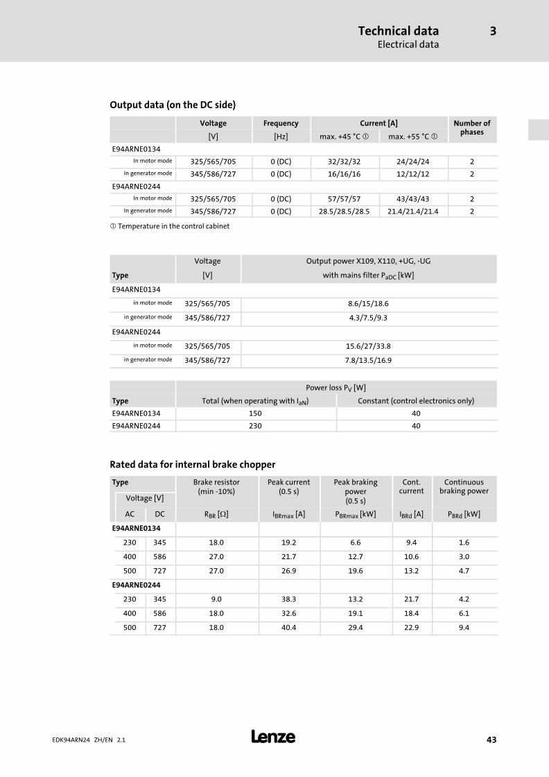
Output data (on the DC side)
Voltage Frequency Current [A] Number ofphases
[V] [Hz] max. +45 °C � max. +55 °C �
E94ARNE0134
In motor mode 325/565/705 0 (DC) 32/32/32 24/24/24 2
In generator mode 345/586/727 0 (DC) 16/16/16 12/12/12 2
E94ARNE0244
In motor mode 325/565/705 0 (DC) 57/57/57 43/43/43 2
In generator mode 345/586/727 0 (DC) 28.5/28.5/28.5 21.4/21.4/21.4 2
� Temperature in the control cabinet
Voltage Output power X109, X110, +UG, −UG
Type [V] with mains filter PaDC [kW]
E94ARNE0134
in motor mode 325/565/705 8.6/15/18.6
in generator mode 345/586/727 4.3/7.5/9.3
E94ARNE0244
in motor mode 325/565/705 15.6/27/33.8
in generator mode 345/586/727 7.8/13.5/16.9
Power loss PV [W]
Type Total (when operating with IaN) Constant (control electronics only)
E94ARNE0134 150 40
E94ARNE0244 230 40
Rated data for internal brake chopper
Type Brake resistor(min −10%)
Peak current(0.5 s)
Peak brakingpower(0.5 s)
Cont.current
Continuousbraking power
Voltage [V]
AC DC RBR [�] IBRmax [A] PBRmax [kW] IBRd [A] PBRd [kW]
E94ARNE0134
230 345 18.0 19.2 6.6 9.4 1.6
400 586 27.0 21.7 12.7 10.6 3.0
500 727 27.0 26.9 19.6 13.2 4.7
E94ARNE0244
230 345 9.0 38.3 13.2 21.7 4.2
400 586 18.0 32.6 19.1 18.4 6.1
500 727 18.0 40.4 29.4 22.9 9.4
Technical dataFuses and cable cross−sections
3
� 44 EDK94ARN24 ZH/EN 2.1
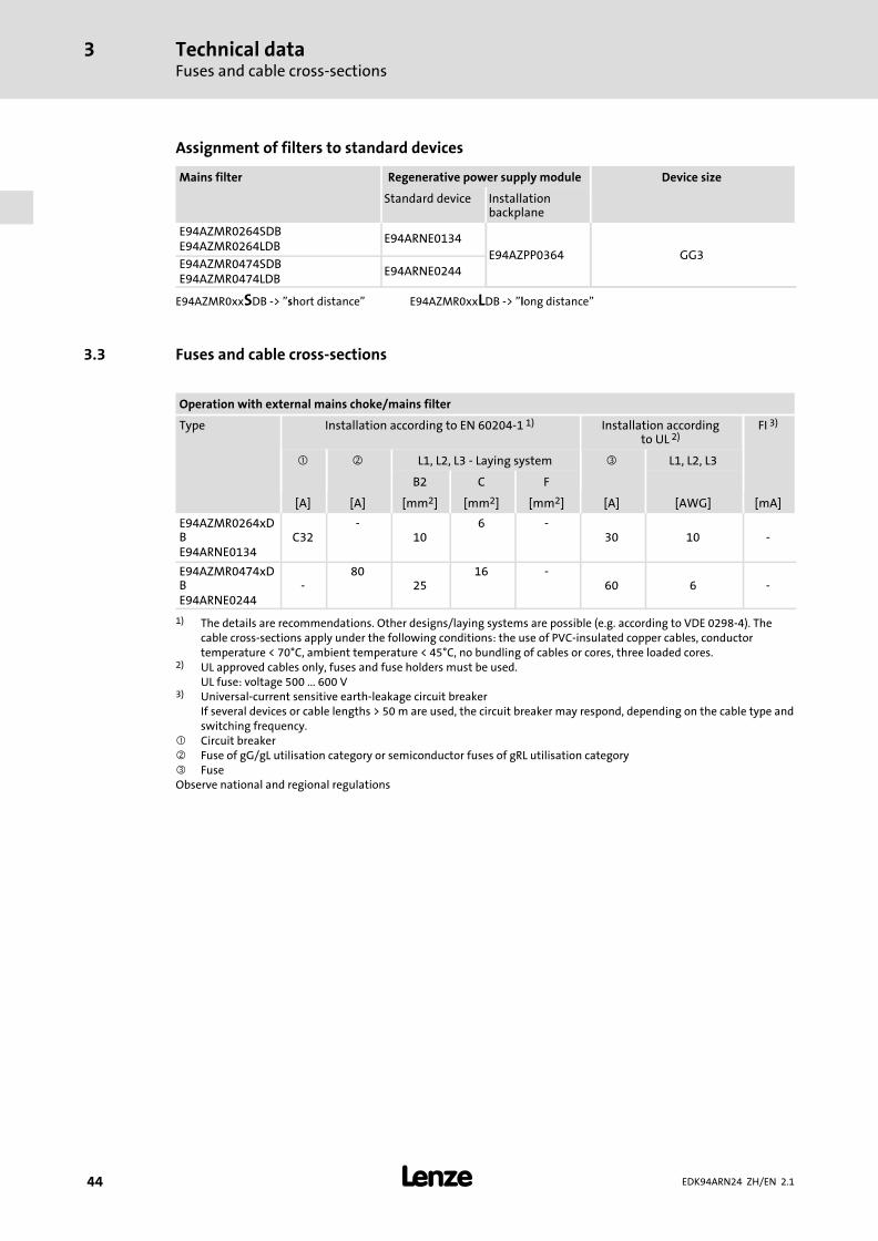
Assignment of filters to standard devices
Mains filter Regenerative power supply module Device size
Standard device Installationbackplane
E94AZMR0264SDBE94AZMR0264LDB
E94ARNE0134
E94AZPP0364 GG3E94AZMR0474SDBE94AZMR0474LDB
E94ARNE0244
E94AZMR0xxSDB −> "short distance" E94AZMR0xxLDB −> "long distance"
3.3 Fuses and cable cross−sections
Operation with external mains choke/mains filter
Type Installation according to EN 60204−1 1) Installation accordingto UL 2)
FI 3)
� � L1, L2, L3 − Laying system � L1, L2, L3
B2 C F
[A] [A] [mm2] [mm2] [mm2] [A] [AWG] [mA]
E94AZMR0264xDBE94ARNE0134
C32−
106 −
30 10 −
E94AZMR0474xDBE94ARNE0244
−80
2516 −
60 6 −
1) The details are recommendations. Other designs/laying systems are possible (e.g. according to VDE 0298−4). Thecable cross−sections apply under the following conditions: the use of PVC−insulated copper cables, conductortemperature < 70°C, ambient temperature < 45°C, no bundling of cables or cores, three loaded cores.
2) UL approved cables only, fuses and fuse holders must be used. UL fuse: voltage 500 ... 600 V
3) Universal−current sensitive earth−leakage circuit breaker If several devices or cable lengths > 50 m are used, the circuit breaker may respond, depending on the cable type andswitching frequency.
� Circuit breaker� Fuse of gG/gL utilisation category or semiconductor fuses of gRL utilisation category� FuseObserve national and regional regulations

Technical dataMechanical data
3
� 45EDK94ARN24 ZH/EN 2.1
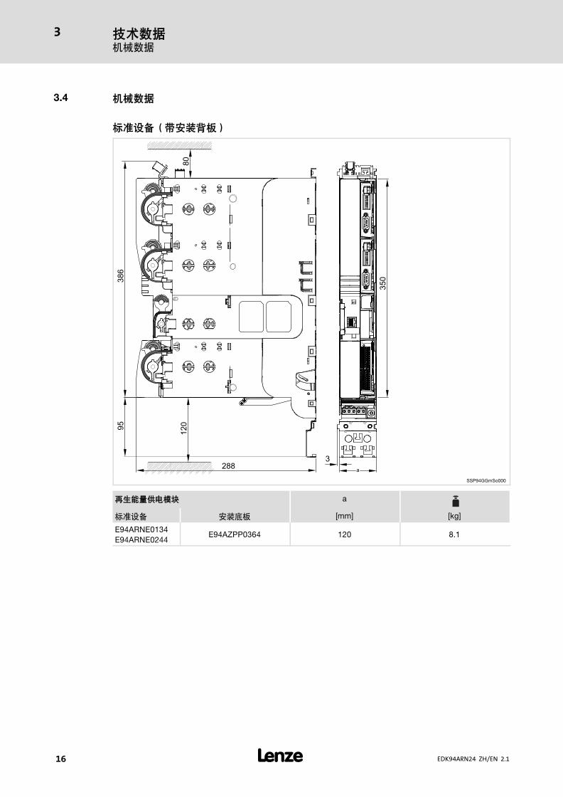
3.4 Mechanical data
Standard device with installation backplane
SSP94GGmSo000
Regenerative power supply module a
Standard device Installation backplane [mm] [kg]
E94ARNE0134E94ARNE0244
E94AZPP0364 120 8.1
Mounting and wiring the installation backplane4
� 46 EDK94ARN24 ZH/EN 2.1
4 Mounting and wiring the installation backplane
� Note!
The devices must be installed in housings (e.g. control cabinets) to meetapplicable regulations.
Mounting and wiring of the installation backplane is described in the Mounting Instructions for the
installation backplane.
Mounting the standard device 5
� 47EDK94ARN24 ZH/EN 2.1
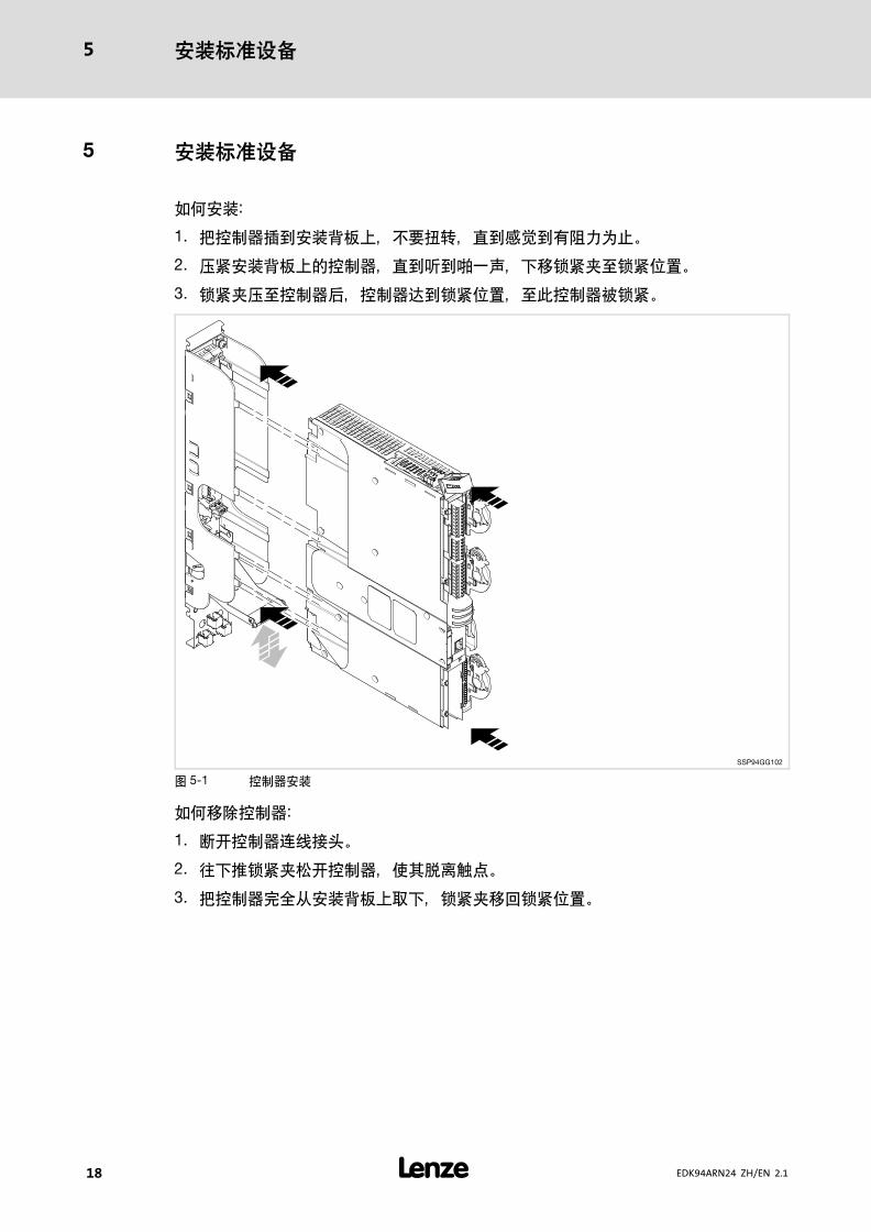
5 Mounting the standard device
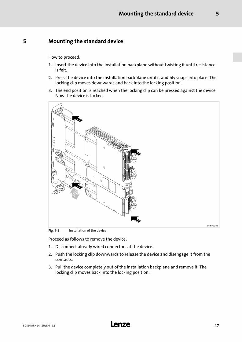
How to proceed:
1. Insert the device into the installation backplane without twisting it until resistanceis felt.
2. Press the device into the installation backplane until it audibly snaps into place. Thelocking clip moves downwards and back into the locking position.
3. The end position is reached when the locking clip can be pressed against the device.Now the device is locked.
SSP94GG102
Fig. 5−1 Installation of the device
Proceed as follows to remove the device:
1. Disconnect already wired connectors at the device.
2. Push the locking clip downwards to release the device and disengage it from thecontacts.
3. Pull the device completely out of the installation backplane and remove it. Thelocking clip moves back into the locking position.

Wiring of the standard device6
� 48 EDK94ARN24 ZH/EN 2.1
6 Wiring of the standard device
Danger!
Dangerous electrical voltage
All power terminals remain live for up to three minutes after mainsdisconnection.
Possible consequences:
ƒ Death or severe injuries when touching the power terminals.
Protective measures:
ƒ Switch off the power supply and wait for at least three minutes beforeworking on the power terminals.
ƒ Make sure that all power terminals are deenergised.
� Stop!
The device contains components that can be destroyed by electrostaticdischarge!
Before working on the device, the personnel must ensure that they are free ofelectrostatic charge by using appropriate measures.
Design of the cables
ƒ The cables used must comply with the approvals required for the location (e.g. UL).
ƒ The effectiveness of a shielded cable is reached by:
– Providing a good shield connection through large−surface shield contact.
– Using only braided shields with low shield resistance made of tin−plated ornickel−plated copper braid.
– Using braided shields with an overlap rate > 70 % and an overlap angle of 90 °.
– Keeping unshielded cable ends as short as possible.
Use system cables or shielded cables for these connections:
ƒ Analog signals (inputs and outputs)
ƒ CAN system bus
ƒ Resolver
ƒ System connection for synchronisation
The following connections need not be shielded:
ƒ 24 V supply
ƒ Digital signals (inputs and outputs)
Wiring of the standard device 6
� 49EDK94ARN24 ZH/EN 2.1
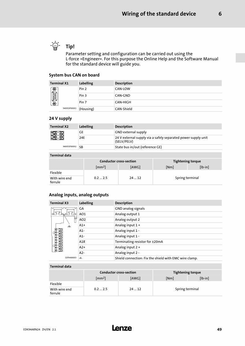
� Tip!
Parameter setting and configuration can be carried out using theL−force »Engineer«. For this purpose the Online Help and the Software Manualfor the standard device will guide you.
System bus CAN on board
Terminal X1 Labelling Description
Pin 2 CAN−LOW
Pin 3 CAN−GND
Pin 7 CAN−HIGH
9400SSP000X1 (Housing) CAN−Shield
24 V supply
Terminal X2 Labelling Description
GE GND external supply
24E 24 V external supply via a safely separated power supply unit(SELV/PELV)
9400SSP000X2 SB State bus in/out (reference GE)
Terminal data
Conductor cross−section Tightening torque
[mm2] [AWG] [Nm] [lb−in]
Flexible
0.2 ... 2.5 24 ... 12 Spring terminalWith wire endferrule
Analog inputs, analog outputs
Terminal X3 Labelling Description
GA GND analog signals
AO1 Analog output 1
AO2 Analog output 2
A1+ Analog input 1 +
A1− Analog input 1 −
A1− Analog input 1 −
A1R Terminating resistor for ±20mA
A2+ Analog input 2 +
A2− Analog input 2 −SSP94000X3 � Shield connection: Fix the shield with EMC wire clamp.
Terminal data
Conductor cross−section Tightening torque
[mm2] [AWG] [Nm] [lb−in]
Flexible
0.2 ... 2.5 24 ... 12 Spring terminalWith wire endferrule

Wiring of the standard device6
� 50 EDK94ARN24 ZH/EN 2.1
Digital outputs
Terminal X4 Labelling Description
GO GND digital out
24O 24−V digital out
DO1 Digital output 1
DO2 Digital output 2
DO3 Digital output 39400SSP000X4 DO4 Digital output 4
Terminal data
Conductor cross−section Tightening torque
[mm2] [AWG] [Nm] [lb−in]
Flexible
0.2 ... 2.5 24 ... 12 Spring terminalWith wire endferrule
Digital inputs
Terminal X5 Labelling Description
GI GND digital in
RFR Controller enable
DI1 Digital input 1
DI2 Digital input 2
DI3 Digital input 3
DI4 Digital input 4
DI5 Digital input 5
DI6 Digital input 6
DI7 Digital input 79400SSP000X5 DI8 Digital input 8
Terminal data
Conductor cross−section Tightening torque
[mm2] [AWG] [Nm] [lb−in]
Flexible
0.2 ... 2.5 24 ... 12 Spring terminalWith wire endferrule

Wiring of the standard device 6
� 51EDK94ARN24 ZH/EN 2.1
Diagnostics/keypad
Terminal X6 Labelling Description
Internal interface, RJ69 socket, for keypad or diagnostic adapter
9400SSP000X6
Resolver
Terminal X7 Labelling Description
1 +REF
2 −REF
3 VCC
4 +COS
5 −COS
6 +SIN
7 −SIN
8 +KTY9400SSP000X7 9 −KTY
System connection for synchronisation
X8terminal Labelling Description
1
Must only be used in conjunctionwith the E94AZMR0xx4xDB mainsfilter, X324...
9400SSP000X8 15
Wiring the device modulesCommunication modules
7
� 52 EDK94ARN24 ZH/EN 2.1
7 Wiring the device modules
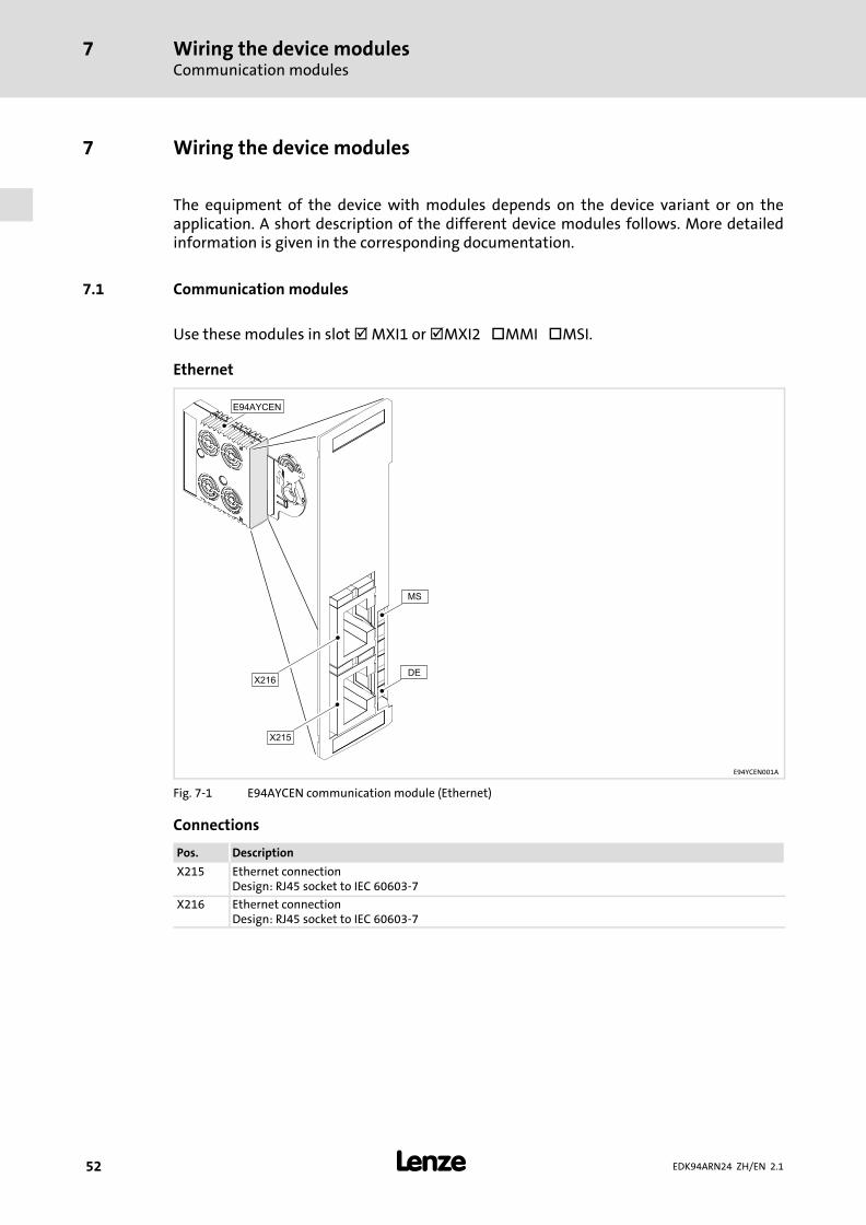
The equipment of the device with modules depends on the device variant or on theapplication. A short description of the different device modules follows. More detailedinformation is given in the corresponding documentation.
7.1 Communication modules
Use these modules in slot � MXI1 or �MXI2 �MMI �MSI.
Ethernet
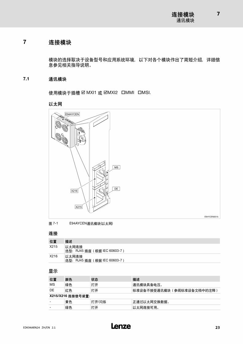
E94YCEN001A
Fig. 7−1 E94AYCEN communication module (Ethernet)
Connections
Pos. Description
X215 Ethernet connectionDesign: RJ45 socket to IEC 60603−7
X216 Ethernet connectionDesign: RJ45 socket to IEC 60603−7
Wiring the device modulesCommunication modules
7
� 53EDK94ARN24 ZH/EN 2.1
Displays
Pos. Colour State Description
MS Green On The communication module is supplied with voltage.
DE Red On The communication module is not accepted by the basicdevice (see notes given in the documentation for thebasic device).
Signals at connection X215/X216:
− Yellow On / blinking Data is being exchanged via Ethernet.
− Green On Ethernet connection is available.
Wiring the device modulesCommunication modules
7
� 54 EDK94ARN24 ZH/EN 2.1
CANopen
E94YCCA001B
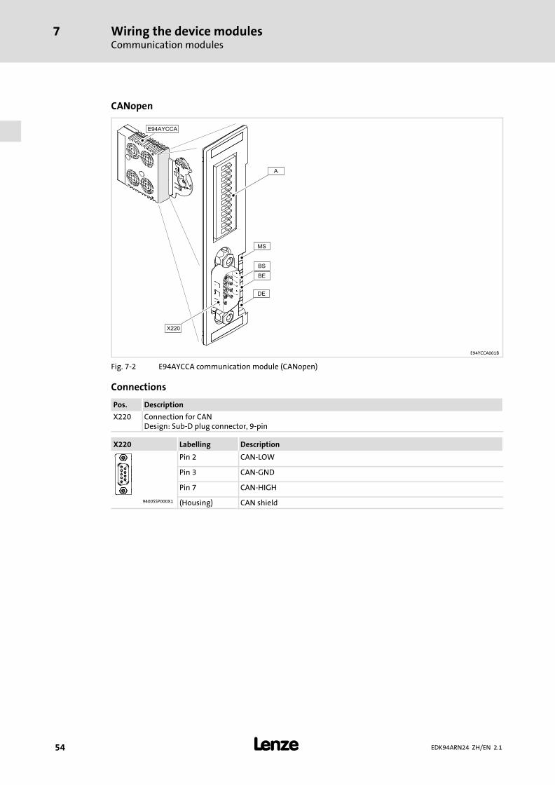
Fig. 7−2 E94AYCCA communication module (CANopen)
Connections
Pos. Description
X220 Connection for CANDesign: Sub−D plug connector, 9−pin
X220 Labelling Description
Pin 2 CAN−LOW
Pin 3 CAN−GND
Pin 7 CAN−HIGH
9400SSP000X1 (Housing) CAN shield

Wiring the device modulesCommunication modules
7
� 55EDK94ARN24 ZH/EN 2.1
DIP switch
Pos. Description
� Addressing of the bus node
Baud CAN Address
ON cd b a 64 32 16 8 4 2 1A
9400CAN003
Fig. 7−3 Arrangement and labelling of the DIP switches
For the DIP switches that are placed at the front
ƒ the node address (labelling "1" ... "64") and
ƒ baud rate (labelling "a" ... "d")
can be set.
� Note!
If all address switches adopt the "OFF" position when the basic device isswitched on, the configurations of codes C00350 (nodes address) and C00351(baud rate) apply.
Switch the voltage supply of the basic device off and then on again to activatealtered settings.
Setting the node address
The node address of the drive is calculated from the sum of all address switches in the "ON"position.
Setting the baud rate
d c b a Baud rate
OFF ON ON OFF 10 kbit/s
OFF ON OFF ON 20 kbit/s
OFF OFF ON ON 50 kbit/s
OFF OFF ON OFF 125 kBit/s
OFF OFF OFF ON 250 kbit/s
OFF OFF OFF OFF 500 kbit/s
ON ON ON OFF 800 kbit/s
OFF ON OFF OFF 1000 kbit/s
OFF ON ON ON Auto baud
Displays
Pos. Colour Condition Description
MS Green On Communication module is supplied with voltage.
DE Red On Communication module is not accepted by the standard device(see notes given in the documentation for the standard device).
BS Green Signalling accordingto DR303−3
CANopen state ("Z")
BE Red CANopen error ("F")

Wiring the device modulesCommunication modules
7
� 56 EDK94ARN24 ZH/EN 2.1
PROFIBUS
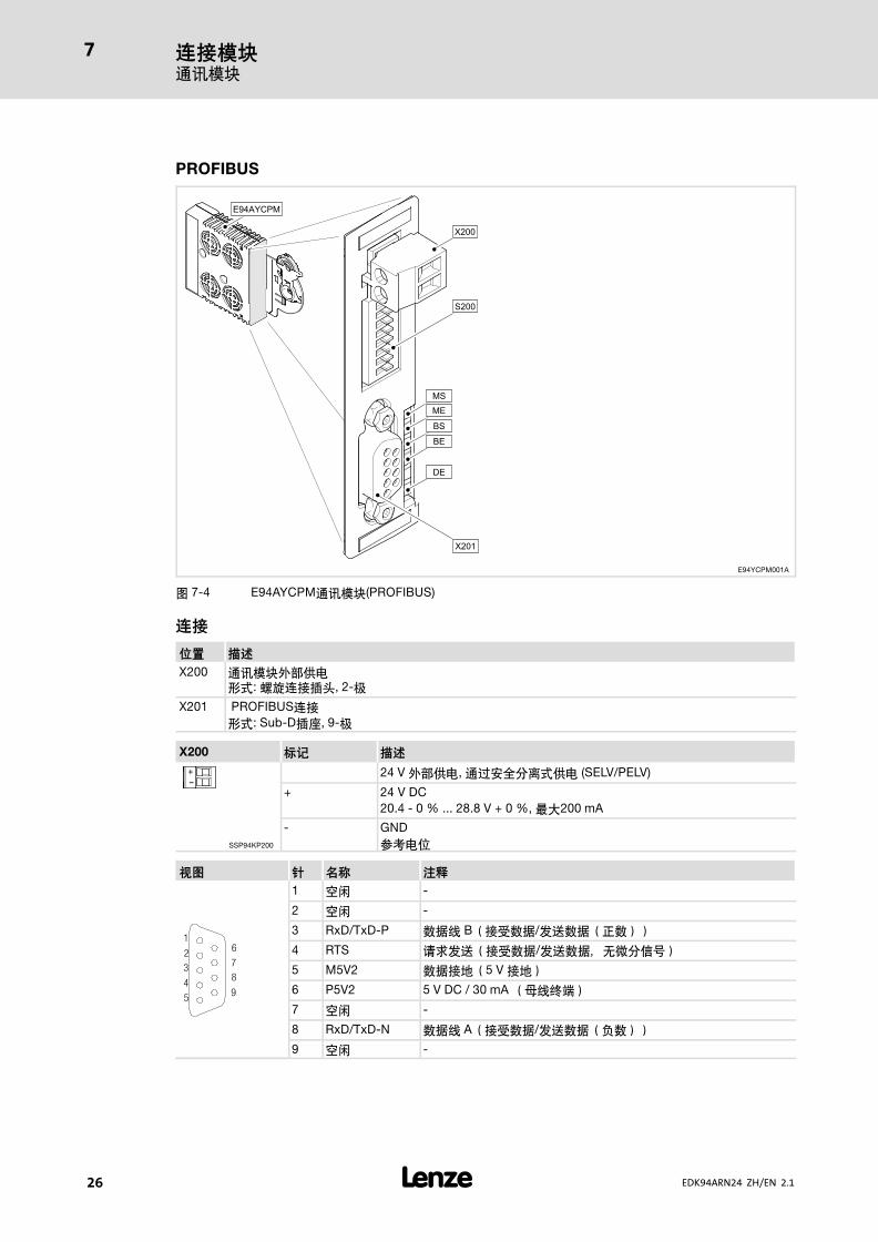
E94YCPM001A
Fig. 7−4 E94AYCPM communication module (PROFIBUS)
Connections
Pos. Description
X200 External supply of the communication moduleDesign: Plug connector with screw connection, 2−pole
X201 Connection for PROFIBUSDesign: Sub−D socket, 9−pole
X200 Labelling Description
+-
24 V external supply via a safely separated power supply unit (SELV/PELV)
+ 24�V�DC20.4 − 0�% ... 28.8 V�+ 0�%, max. 200 mA
SSP94KP200
− GNDReference potential
View Pin Designation Explanation
1
2
3
4
5
6
7
8
9
1 free −
2 free −
3 RxD/TxD−P Data line B (received data/transmitted data plus)
4 RTS Request To Send (received data/transmitted data, no differentialsignal)
5 M5V2 Data ground (ground to 5V)
6 P5V2 5 V DC / 30 mA (bus termination)
7 free −
8 RxD/TxD−N Data line A (received data/transmitted data minus)
9 free −

Wiring the device modulesCommunication modules
7
� 57EDK94ARN24 ZH/EN 2.1
DIP switch
Pos. Description
A Addressing of the station
For addressing purposes, every station must be given an unambiguous address.
Valid address range: 1 126
The address can be set freely via the front−panel switch.
� Note!
ƒ For S1 − S7 = OFF (Lenze setting):
When switching on the module, the configuration set under code C00899becomes active.
ƒ For one of the switches S1 − S7 = ON:
When switching on the module, the address resulting from the switchsetting becomes active.
Switch off the voltage supply of the communication module and then on againin order to activate changed settings.
Address settings through the DIP switch (device front)
The sum of the values (identical with package labelling) results in the station address to beset:
Example:
Switch S7 S6 S5 S4 S3 S2 S1
Package labelling «64» «32» «16» «8» «4» «2» «1»
Switch state 0 0 1 0 1 1 1
Address (= 23) 0 0 16 0 4 2 1
Displays
LED
DescriptionPos. Colour Condition
MS Green Blinking Communication module is supplied with voltage, but has no connectionto the standard device (standard device is switched off, initialising or notpresent).
On Communication module is supplied with voltage and connected to thestandard device.
ME Red On An error has occurred on the communication module.
BS Green Blinking Communication via the communication module has been established.The PROFIBUS is active.
BE Red On Bus monitoring has been triggered.
DE Red On The communication module is not accepted by the standard device (seenotes given in the instructions for the standard device)

Wiring the device modulesMemory modules
7
� 58 EDK94ARN24 ZH/EN 2.1
7.2 Memory modules
Use these modules in slot � MXI1 �MXI2 �MMI �MSI.
MM220
Equipment MM220:
ƒ 1 MB flash memory
ƒ System bus address switch (CAN)
SSP94M1001
Fig. 7−5 Memory module with DIP switch (as of order designation E94AYM22)
Baud CAN Address
ON cd b a 64 32 16 8 4 2 1A
9400CAN003
Fig. 7−6 Arrangement and labelling of the DIP switches
For the DIP switches that are placed at the front
ƒ the node address (labelling "1" ... "64") and
ƒ baud rate (labelling "a" ... "d")
can be set.
� Note!
If all address switches adopt the "OFF" position when the basic device isswitched on, the configurations of codes C00350 (nodes address) and C00351(baud rate) apply.
Switch the voltage supply of the basic device off and then on again to activatealtered settings.

Wiring the device modulesSafety modules
7
� 59EDK94ARN24 ZH/EN 2.1
Setting the node address
The node address of the drive is calculated from the sum of all address switches in the "ON"position.
Setting the baud rate
d c b a Baud rate
OFF ON ON OFF 10 kbit/s
OFF ON OFF ON 20 kbit/s
OFF OFF ON ON 50 kbit/s
OFF OFF ON OFF 125 kBit/s
OFF OFF OFF ON 250 kbit/s
OFF OFF OFF OFF 500 kbit/s
ON ON ON OFF 800 kbit/s
OFF ON OFF OFF 1000 kbit/s
OFF ON ON ON Auto baud
7.3 Safety modules
If the regenerative power supply module is used, safety functions are not available.However, the SM0 module in the MSI slot is mandatory for the operation of theregenerative power supply module.
Final worksInitial commissioning at a mains voltage of 400 V
8
� 60 EDK94ARN24 ZH/EN 2.1
8 Final works
8.1 Initial commissioning at a mains voltage of 400 V
The regenerative power supply module can be operated at a mains voltage of 400 V afterit has been installed according to these mounting instructions.
For this purpose, regenerative feedback is activated via the digital RFR input.
How to proceed:
1. Switch−on the mains voltage of 24 V.
– for the mains filter
– for the regenerative power supply module (optional)
2. Switch−on the mains voltage of 400 V.
3. Activate/deactivate regenerative feedback via the digital RFR input.
8.2 Initial commissioning at a mains voltage of 230 or 500 V
At first, the mains voltage must be set in the regenerative power supply module for theoperation at a mains voltage of 230 or 500 V. The setting will be done in C00173 and canbe carried out using a keypad or the Lenze Engineer PC software.
Required for the commissiong:
ƒ A EZAEBKx00xkeypad
or
ƒ A computer with a Windows® operating system (XP or 2000)
ƒ The Lenze Engineer PC software
ƒ A connection to the regenerative power supply module via an interface, e.g.
– X6 diagnostic interface with USB diagnostic adapter
– CAN system bus
– Communication modules in the M1/M2 expansion slots
ƒ The software manual for the technology application used
ƒ The communication manual for the network of the automation platform
ƒ Switch−on the mains voltage of 24 V.
– for the mains filter
– for the regenerative power supply module
After the setting has been carried out according to the existing mains voltage:
1. Switch−on the mains voltage.
2. Activate/deactivate regenerative feedback via the digital RFR input.
Final worksFurther settings
8
� 61EDK94ARN24 ZH/EN 2.1
8.3 Further settings
Follow the instructions of the software and/or read the documentation on theparameterisation of the regenerative power supply module.
�© 08/2014
� Lenze Automation GmbHPostfach 10 13 52, D−31763 HamelnHans−Lenze−Str. 1, D−31855 AerzenGermany
Service Lenze Service GmbHBreslauer Straße 3, D−32699 Extertal
Germany
� +49�5154 82−0 � 008000�2446877 (24 h helpline)
� +49�5154 82−2800 � +49�5154�82−1112
� [email protected] � [email protected]
� www.lenze.com
EDK94ARN24 � .P#T � ZH/EN � 2.1 � TD29
10 9 8 7 6 5 4 3 2 1