
E90 AVIN Non-iDrive Head Unit Install with Logic 7 Integration€¦ · E90 AVIN Non-iDrive Head...
10
E90 AVIN Non-iDrive Head Unit Install with Logic 7 Integration Option 1: If you prefer to go an easier route you can order our BMW MOST interface. It would make the install a lot easier and will not require many of the steps in the guide below. The BMW MOST interface is available in the link below https://avinusa.com/bmw-most-fiber-optic-amp-interface-for-e90-e91-e92-e93-e60- e61-e81-e82-e83-e84-e70-e87-e88.html Option 2: PURPOSE: This document provides the basic steps required to: (a) relocate the factory head unit to under the seat, (b) install the AVIN E90 Non-iDrive Head Unit, & (c) integrate the two head units such that audio, and other stock functions can operate seamlessly on the MOST-based Logic 7 system. 1. Remove factory head unit, HVAC controls, trim & factory mounting bracket. There are plenty of DIY’s on this. It’s relatively straight forward. 2. Remove the center console trim, & ash tray
Transcript of E90 AVIN Non-iDrive Head Unit Install with Logic 7 Integration€¦ · E90 AVIN Non-iDrive Head...
E90 AVIN Non-iDrive Head Unit Install with Logic 7 Integration
Option 1: If you prefer to go an easier route you can order our BMW MOST interface.
It would make the install a lot easier and will not require many of the steps in the
guide below.
The BMW MOST interface is available in the link below
https://avinusa.com/bmw-most-fiber-optic-amp-interface-for-e90-e91-e92-e93-e60-
e61-e81-e82-e83-e84-e70-e87-e88.html
Option 2:
PURPOSE: This document provides the basic steps required to: (a) relocate the factory
head unit to under the seat, (b) install the AVIN E90 Non-iDrive Head Unit, & (c)
integrate the two head units such that audio, and other stock functions can operate
seamlessly on the MOST-based Logic 7 system.
1. Remove factory head unit, HVAC controls, trim & factory mounting bracket.
There are plenty of DIY’s on this. It’s relatively straight forward.
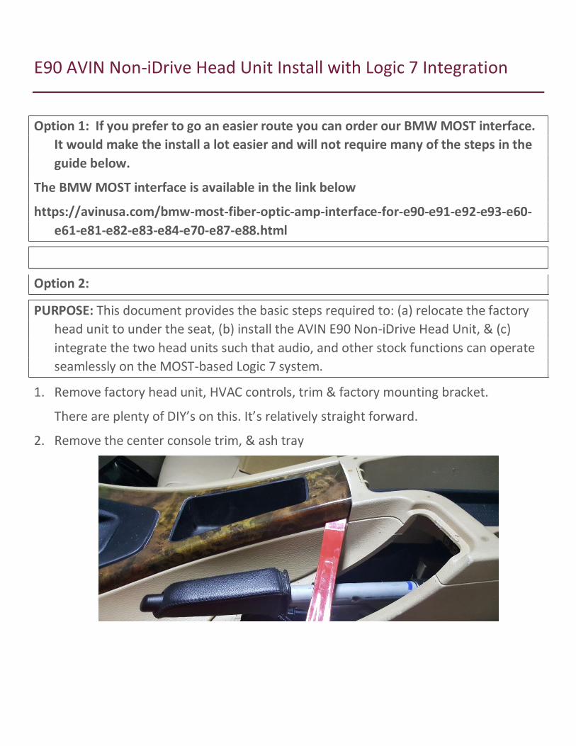
2. Remove the center console trim, & ash tray
Page 2
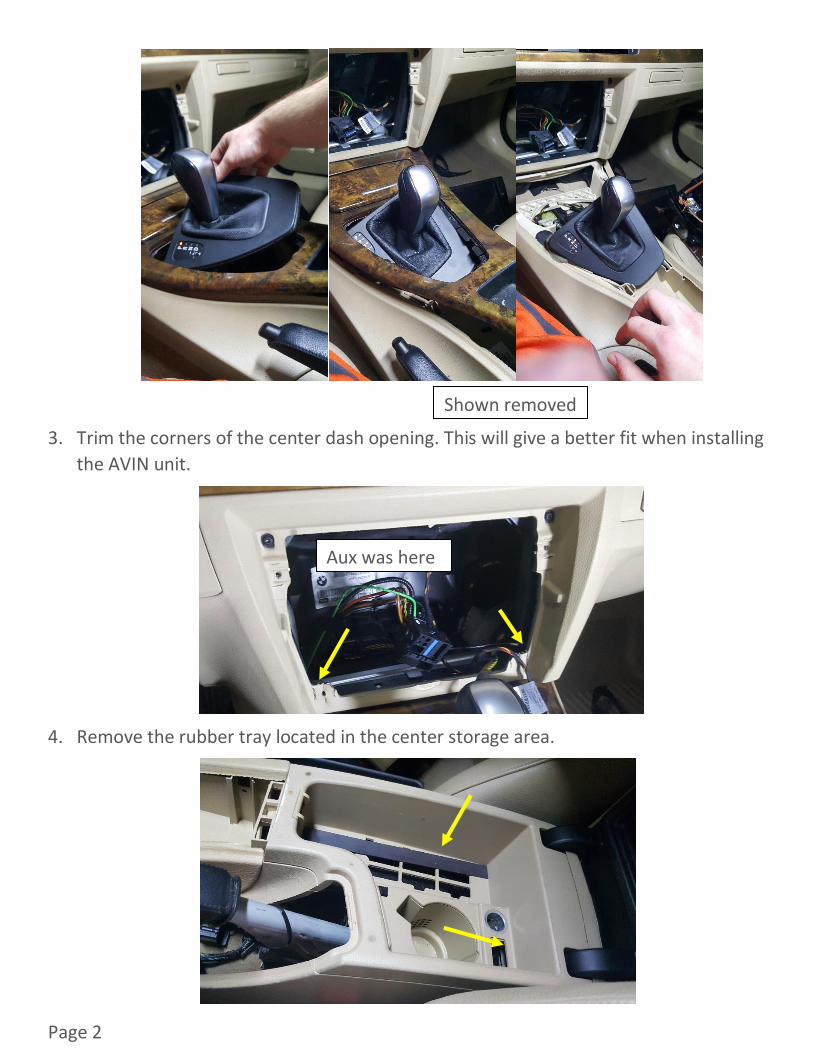
3. Trim the corners of the center dash opening. This will give a better fit when installing
the AVIN unit.
4. Remove the rubber tray located in the center storage area.
Shown removed
Aux was here
Page 3
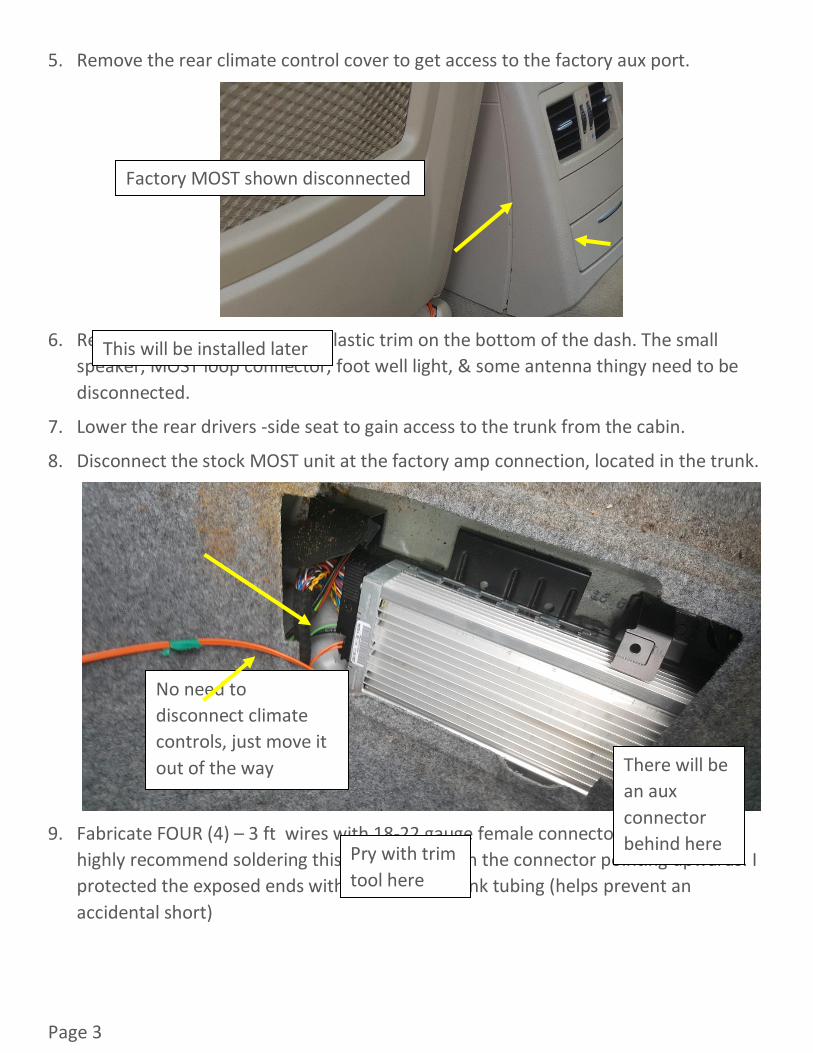
5. Remove the rear climate control cover to get access to the factory aux port.
6. Remove drivers-side foot well plastic trim on the bottom of the dash. The small
speaker, MOST loop connector, foot well light, & some antenna thingy need to be
disconnected.
7. Lower the rear drivers -side seat to gain access to the trunk from the cabin.
8. Disconnect the stock MOST unit at the factory amp connection, located in the trunk.
9. Fabricate FOUR (4) – 3 ft wires with 18-22 gauge female connectors on one end. I
highly recommend soldering this connection with the connector pointing upwards. I
protected the exposed ends with some heat shrink tubing (helps prevent an
accidental short)
No need to
disconnect climate
controls, just move it
out of the way
Pry with trim
tool here
There will be
an aux
connector
behind here
Factory MOST shown disconnected
This will be installed later

Page 4
10. Bundle the four wires together and label them at both ends with the following
descriptions:
o GND – Pin 12. This is the ground wire for the head unit
o +12V – Pin 15. This provides the power to run the head unit
o CAN LO – Pin 9. “LOW” signal wire from the Canbus System.
o CAN HI – Pin 11. “HIGH” signal wire from the Canbus System. Add heat shrink
tubing to this end
One of these goes on
one end of each 3 ft
wire. The other end
is bare (for splicing) The Four wires can
be protected by heat
shrinking as a bundle
Page 5
MAKE SURE THE BATTERY HAS BEEN DISCONNECTED BEFORE COMPLETEING THE NEXT
STEPS!!!!
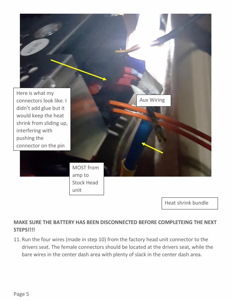
11. Run the four wires (made in step 10) from the factory head unit connector to the
drivers seat. The female connectors should be located at the drivers seat, while the
bare wires in the center dash area with plenty of slack in the center dash area.
Here is what my
connectors look like. I
didn’t add glue but it
would keep the heat
shrink from sliding up,
interfering with
pushing the
connector on the pin
Heat shrink bundle
Aux Wiring
MOST from
amp to
Stock Head
unit
Page 6
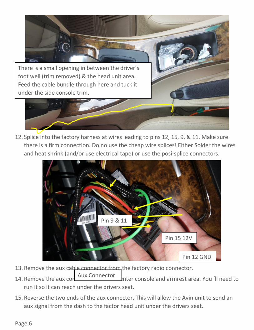
12. Splice into the factory harness at wires leading to pins 12, 15, 9, & 11. Make sure
there is a firm connection. Do no use the cheap wire splices! Either Solder the wires
and heat shrink (and/or use electrical tape) or use the posi-splice connectors.
13. Remove the aux cable connector from the factory radio connector.
14. Remove the aux connector from the center console and armrest area. You ‘ll need to
run it so it can reach under the drivers seat.
15. Reverse the two ends of the aux connector. This will allow the Avin unit to send an
aux signal from the dash to the factor head unit under the drivers seat.
There is a small opening in between the driver’s
foot well (trim removed) & the head unit area.
Feed the cable bundle through here and tuck it
under the side console trim.
Pin 15 12V
Pin 12 GND
Pin 9 & 11
Aux Connector

Page 7
!
16. Run the aftermarket MOST connector from the trunk to under the drivers seat.
Remove these pins and swap so the
connectors are on the opposite
ends .This is a lot easier than pulling
the wire to reverse the connection!
From
AUX
JACK
@
rear
HVAC
cover
From
AUX
HEAD
UNIT
Page 8
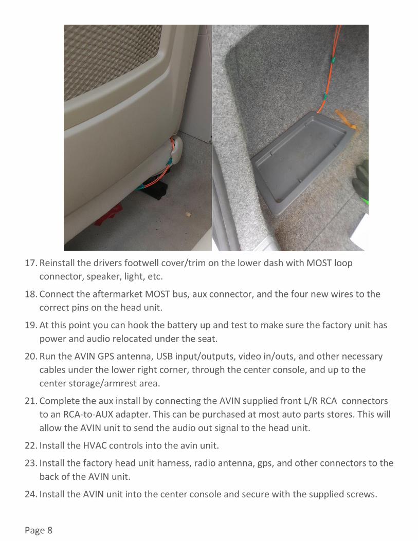
17. Reinstall the drivers footwell cover/trim on the lower dash with MOST loop
connector, speaker, light, etc.
18. Connect the aftermarket MOST bus, aux connector, and the four new wires to the
correct pins on the head unit.
19. At this point you can hook the battery up and test to make sure the factory unit has
power and audio relocated under the seat.
20. Run the AVIN GPS antenna, USB input/outputs, video in/outs, and other necessary
cables under the lower right corner, through the center console, and up to the
center storage/armrest area.
21. Complete the aux install by connecting the AVIN supplied front L/R RCA connectors
to an RCA-to-AUX adapter. This can be purchased at most auto parts stores. This will
allow the AVIN unit to send the audio out signal to the head unit.
22. Install the HVAC controls into the avin unit.
23. Install the factory head unit harness, radio antenna, gps, and other connectors to the
back of the AVIN unit.
24. Install the AVIN unit into the center console and secure with the supplied screws.

Page 9
25. Reinstall the center trim and rear HVAC trim.
26. Turn the unit on and enjoy.
Page 10
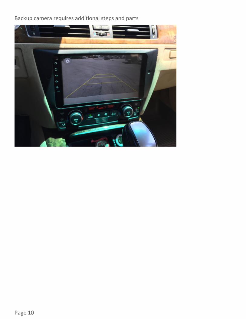
Backup camera requires additional steps and parts