E/73-dW NASA TECHNICAL NOTE NASA TN 0-7373 · PDF fileNASA TECHNICAL NOTE NASA TN 0-7373 m h M...
18
E/73-dW 75 NASA TECHNICAL NOTE NASA TN 0-7373 m h M C APOLLO EXPERIENCE REPORT - THE DEVELOPMENT OF DESIGN-LOADS CRITERIA, METHODS, AND OPERATIONAL AND MIDBOOST CONDITIONS PROCEDURES FOR PRELAUNCH, LIFT-OFF, by Alden C. Mnckey and Robert D, Schwartz Lyndon B. Johnson Space Center Houston, Texas 77058 NATIONAL AERONAUTICS AND SPACE ADMINISTRATION WASHINGTON, D. C. AUGUST 1973 - https://ntrs.nasa.gov/search.jsp?R=19730021143 2018-05-11T19:18:50+00:00Z
Transcript of E/73-dW NASA TECHNICAL NOTE NASA TN 0-7373 · PDF fileNASA TECHNICAL NOTE NASA TN 0-7373 m h M...

E/73-dW 7 5 N A S A TECHNICAL NOTE NASA TN 0-7373
m h M
C
APOLLO EXPERIENCE REPORT - THE DEVELOPMENT OF DESIGN-LOADS CRITERIA, METHODS, AND OPERATIONAL
A N D MIDBOOST CONDITIONS PROCEDURES FOR PRELAUNCH, LIFT-OFF,
by Alden C. Mnckey and Robert D, Schwartz
Lyndon B. Johnson Space Center Houston, Texas 77058
N A T I O N A L AERONAUTICS A N D SPACE A D M I N I S T R A T I O N W A S H I N G T O N , D. C. A U G U S T 1973 -
https://ntrs.nasa.gov/search.jsp?R=19730021143 2018-05-11T19:18:50+00:00Z
~
1. Reporr No.
NASA TN D-7373
11. Contract or Grant No. Lyndon B. Johnson Space Center Houston, Texas 77058
13. Type of Report and Period Covered
Technical Note 2. Sponsoring Agency Name and Address
14. Sponsoring Agency Code National Aeronautics and Space Administration Washington, D. C . 20546
The JSC Director has waived the use of the International System of Units (SI) for this Apollo Experience Report, because, in his judgment, the use of SI units would impair the usefulness of the report o r result in excessive cost.
5. Supplementary Notes
6. Abstract
2. Government Accession No. 3. Recipient's Catalog No.
In this report , the prelaunch, lift-off, and midboost conditions that a r e important to the design of spacecraft a r e described. Original Apollo design concepts that were deficient in realistic and accurate analysis of spacecraft structural loads in a wind environment also a r e included. Important improvements in design criteria, mathematical models, wind-monitoring procedures, and loads analyses a r e discussed. Recommendations for future programs a r e presented.
4. "'1' and Subtitle
rHE DEVELOPMENT OF DESIGN-LOADS CRITERIA, METHODS, APOLLO EXPERIENCE REPORT
IND OPERATIONAL PROCEDURES FOR PRELAUNCH, LIFT-OFF, IND MIDBOOST CONDITIONS 7. Author(s)
Alden C. Mackey and Robert D. Schwartz, JSC -
9. Performing Oryaniration Name and Address
5. Report Date August 197 3
6. Performing Organization Code
8. Performing Organization Report No.
JSC S-342 10. Work Uni t No.
914-50-20- 14-72
17. Key Words (Suggested by Author(s) ) * Apollo Spacecraft Loads
* Spacecraft Design Launching
'Winds Aloft -
Structural Design Launch Vehicle
Ground Wind
18. Distr ibution Statement
19. Security Classif. (o f this report) 20. Security Classif. (of this pagel 21. NO. o f Pages
None None 18
22. Price
$3.00

APOLLO EXPER I ENCE REPORT
THE DEVELOPMENT OF DESIGN-LOADS CRITERIA, METHODS,
AND OPERATIONAL PROCEDURES FOR PRELAUNCH,
LIFT-OFF, AND MIDBOOST CONDITIONS
By Alden C. Mackey and Robert D. Schwartz Lyndon B. Johnson Space Center
SUMMARY
The development of the Apollo spacecraft design loads and operational procedures for prelaunch, lift-off, and midboost conditions is outlined in this report. The design .criteria, mathematical models, loads analyses, changes in vehicle and environmental data, and wind-monitoring procedures are discussed for each condition.
The original cr i ter ia and analyses deficiencies and the important improvements achieved during the design evolution are noted. Recommendations are made for future programs.
INTRODUCTION
Space vehicle structural-design conditions in which wind is a factor warrant exam- ination separate from other design conditions. The wind conditions considered for the Apollo spacecraft design included the prelaunch, lift-off, and boost phases for both the Apollo/Saturn IB and Apollo/Saturn V mission configurations.
With the exception of the lunar module (LM), the Apollo spacecraft, consisting of . the command and service module and spacecraft/lunar module adapter (SLA), was de- veloped in two major phases. The Block I phase included both boilerplate and airframe vehicles used in ground and flight tests. Information from these tests was used in the design and development of the Block I spacecraft and subsequently in the design of the Block I1 spacecraft.
-
On the launch pad, the Apollo/Saturn IB is protected from wind by the support structure, which encloses the spacecraft vehicle and is used for assembly and service until the service structure is rolled back before launch. The concern about wind loads on the Apollo/Saturn V vehicle begins when the space vehicle emerges from the Vertical Assembly Building (VAB). The space vehicle is exposed to ground winds from the time it is transported by the crawler to Launch Complex 39 until the time of launch. An
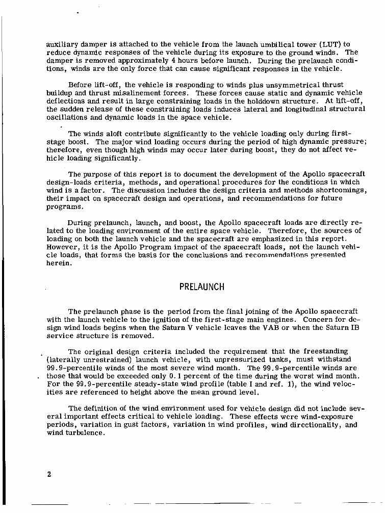
auxiliary damper is attached to the vehicle f rom the launch umbilical tower (LUT) to reduce dynamic responses of the vehicle during its exposure to the ground winds. The damper is removed approximately 4 hours before launch. During the prelaunch condi- tions, winds a r e the only force that can cause significant responses in the vehicle.
Before lift-off, the vehicle is responding to winds plus unsymmetrical thrust buildup and thrust misalinement forces. These forces cause static and dynamic vehicle deflections and result in large constraining loads in the holddown structure. At lift-off, the sudden release of these constraining loads induces lateral and longitudinal structural oscillations and dynamic loads in the space vehicle.
The winds aloft contribute significantly to the vehicle loading only during f i rs t - stage boost. The major wind loading occurs during the period of high dynamic pressure; therefore, even though high winds may occur later during boost, they do not affect ve- hicle loading significantly.
The purpose of this report is to document the development of the Apollo spacecraft design-loads cri teria, methods, and operational procedures for the conditions in which wind is a factor. The discussion includes the design cr i ter ia and methods shortcomings, their impact on spacecraft design and operations, and recommendations for future programs.
During prelaunch, launch, and boost, the Apollo spacecraft loads are directly re- lated to the loading environment of the entire space vehicle. Therefore, the sources of loading on both the launch vehicle and the spacecraft are emphasized in this report . However, i t is the Apollo Program impact of the spacecraft loads, not the launch vehi- cle loads, that forms the basis for the conclusions and recommendations presented herein.
PRELAUNCH
The prelaunch phase is the period from the final joining of the Apollo spacecraft with the launch vehicle to the ignition of the first-stage main engines. Concern for de- sign wind loads begins when the Saturn V vehicle leaves the VAB or when the Saturn 1B service structure is removed.
The original design cr i ter ia included the requirement that the freestanding (laterally unrestrained) launch vehicle, with unpressurized tanks, must withstand 99.9-percentile winds of the most severe wind month. The 99.9-percentile winds are
. those that would be exceeded only 0.1 percent of the time during the worst wind month. For the 99.9-percentile steady-state wind profile (table I and ref. l), the wind veloc- ities are referenced to height above the mean ground level.
The definition of the wind environment used for vehicle design did not include sev- e ra l important effects critical to vehicle loading. These effects were wind-exposure periods, variation in gust factors, variation in wind profiles, wind directionality, and wind turbulence.
2

TABLE I. - SURFACE-WINDSPEED ENVELOPE 99.9 PERCENTILE
FOR EASTERN TEST RANGE^
Height above natural grade
m
3.0
9.1
18.3
30.5
61.0
91.4
121.9
152.4
ft
10
30
60
100
200
300
400
500
Quasi-steady-state windspeed
m/sec
11.8
14.8
16.9
18.8
21.6
23.4
24.7
25.9
knots
23.0
28.7
32.9
36.5
41.9
45.4
48.1
50.3
b Peak windspeed
m/sec
16.6
20.7
23.7
26.3
30.2
32.7
34.6
36.2
%ind velocity distribution with height is
where V = wind velocity at desired height
= wind velocity at reference height 'Ref h = altitude at which wind velocity is desired
= reference altitude hRef
bPeak wind velocity is 1.4 times steady-state wind velocity
knots
32.2
40.2 *
46.1
51.1
58.7
63.6
67.3
70.4
3

The 99.9-percentile steady-state wind profile used in the original design was based on the assumption that the space vehicle would be exposed to the ground-wind en- vironment for only a few hours; that is, the vehicle would be transported from the VAB to the launch pad and launched within a few hours. However, most Apollo/Saturn vehi- cles were exposed to the launch pad environment for several months. A realistic ex- posure period would have resulted in higher magnitudes for the 99.9-percentile winds; hence, the original cr i ter ia were not adequate. The exposure-period definition was the most important deficiency in the ground-wind environment, but the other listed defi- ciencies also were significant.
To evaluate the complex effects that contribute to the definition of the winds in the boundary layer of the atmosphere, a 150-meter meteorological tower facility was con- structed in the Merritt Island Launch Area at the NASA John F. Kennedy Space Center (KSC) in Florida. A complete description of the tower is given in reference 2. Data obtai’ned from this meteorological facility a r e useful for the study of the characterist ics of the lower atmosphere wind and temperature profiles as a function of height and time, gust-shape phenomena, turbulence spectra, correlation properties of steady-state and turbulent flow, and calculations of diffusion parameters that define the environment to which the space vehicles would be exposed during the prelaunch period.
Although the environment definition used in ground-wind design cr i ter ia w a s orig- inally deficient in several a reas , it was later improved. A complete description of the present definition is given in reference 3.
As wind flows by a cylinder, the wake behind the cylinder is disturbed and is char- acterized by distinct vortexes, as shown in figure 1. Clockwise and counterclockwise vortexes a re shed in an alternate regular manner. The Von Karman vortex shedding causes a harm-n~ica!!;~ ~ a r y i n g fsrce oii the cyiirider normai to tne wind direction (ref . 4). Originally, vortex-shedding load for design loads was assumed to be 1.25 times the drag load resulting from steady-state winds. In 1963, a wind-tunnel test program was initiated to define the dynamic response of the Apollo/Saturn vehicles, particularly the vortex-shedding response. Two separate series of tes t s were run on the freestanding Apollo/Saturn IB and Saturn V vehicles. Vehicle response to vortex shedding w a s identified as a potential problem, and further tes ts were planned.
Ft
L FD = Drag force
F = L i f t force L
Figure 1. - Vortexes shedding in a wake.
In the fall of 1964, a third series of wind-tunnel tes ts was initiated on the Apollo/ Saturn V configuration. The tes t model in- cluded the space vehicle and the LUT but not the mobile service structure. Testing was completed on empty, intermediate, and fully fueled vehicles. During the tes ts , the vortex-shedding response w a s identified as a crit ical launch vehicle loading condition for empty and intermediate propellant weights. The change in vehicle propellant weights a l ters the elastic vibrational char- acter is t ics of the vehicle, which in turn affect the vehicle vortex-shedding response. Several potential fixes, such as helical
4

strakes, were evaluated on the test model. These tested fixes, which would have al- tered the aerodynamic configuration, were rejected, and an auxiliary damper was rec- ommended. A fourth ser ies of wind-tunnel tests was completed i n June 1966. The test model was modified to include the effects of the mobile service structure, and testing was performed for the empty and intermediate propellant conditions. The resul ts from these tes ts were used to develop a viscous damping system that was installed on subse- quent Apollo/Saturn V operational vehicles. This damping system was attached between the LUT and the command module (CM) launch escape system tower (fig. 2).
As a result of the wind-tunnel tes ts , the original 1.25 vortex-shedding factor for design was changed. For vehicle ground operations with the damping system attached and unattached, the vortex-shedding load w a s assumed to be, respectively, 1.6 and 3.6 t imes the drag load resulting from steady-state winds.
The final wind-tunnel test on the Apollo/Saturn V configurations w a s completed during June 1967. The purpose of the test was to evaluate ground-wind boundary layer effects on the dynamic response of the vehicle. The test indicated that ground-wind boundary layer effects could be ignored in the prediction of dynamic response for the ground-wind loads condition. Primarily, this insensitivity to boundary layer effects is caused by the small variation along the vehicle of the design wind magnitude.
Figure 2.- Viscous damper for Apollo/Saturn V.
The third and final se r ies of wind- tunnel tes ts on the Apollo/Saturn IB vehicle was completed during the spring of 1965. In this testing, numerous wind azimuths were investigated for full and empty propel- lant conditions and for empty conditions (the more severe weight condition). No critical condition was identified during the Apollo/ Saturn IB test; hence, no further testing was required.
The high dynamic responses measured i n the Apollo/Saturn V wind-tunnel tests caused concern about the ability of the vehi- cle to withstand the on-pad environment. In an effort to verify the results f rom the wind- tunnel tes ts , ground-wind tests were initi- ated using a full-scale Apollo/Saturn V facilities verification vehicle. The objec- ’ tives of the tes ts were to evaluate the re - sponse of the Apollo/Saturn V during transportation from the VAB to Launch Complex 39 and to measure vehicle response during exposure to launch pad environment fo r long time periods. The pad 39 tes ts started on May 25, 1966, and were com- pleted on October 14, 1966. During the testing period, the vehicle w a s returned to the VAB (June 8 to 10, 1966) for protection from a hurricane that passed through the
5

area. Data from the tes ts were inconclusive in defining the vehicle response to ground winds. High-magnitude winds were experienced only during the time of the hurricane, but no loads o r accelerations were recorded during that period because of an instrumen- tation systems failure. Also, to preclude the possibility of a structural failure, a damper was attached from the LUT to station 2560 in the S-II/S-IVB interstage. With the addition of this damper, overall structural damping for the vehicle was calculated to be 5.5 percent compared with the assumed 1 percent for the vehicle structure with- out auxiliary damping. Dynamic response of the vehicle was restricted severely by damping of this magnitude, and the Von Karman vortex-shedding effect was never de- tected during the course of the test.
. Data f rom wind-tunnel and full-scale tests did result in the viscous damping sys- tem being installed to reduce vehicle dynamic loads, but the data were available too late for inclusion in space vehicle design. The installation of the viscous damping sys- tem eliminated the high dynamic responses to winds and resulted in prelaunch loads be- low the structural capability of the space vehicle. Two significant lessons that apply to ground-wind environment and loads definition were learned from the Apollo/Saturn program. First, an accurate definition of the vehicle exposure to the launch pad en- vironment is required. Second, wind-tunnel testing for ground winds should be timely so that the results can be considered in the vehicle design.
LAUNCH
The launch period is the time from the initiation of first-stage start sequence un- til all structural response transients following vehicle release have damped out. The structural response and accompanyir.g inertia! loads zre caused primariiy by a lift-off phenomenon often called "twang. '' Twang is the vehicle dynamic response to the sudden release at the holddown a r m s of the constraining shear , moment, and axial forces. These holddown forces are caused by the ground winds and thrust buildup before release. Therefore, the calculation of design lift-off loads is dependent on an accurate definition of the wind- and propulsion-induced loading environments and an accurate mathematical model describing the structural response. The advent of the large, flexible Apollo/ Saturn IB and Saturn V vehicles was a unique opportunity to advance the state of the a r t in calculating lift-off loads; however, in the calculation process, several deficiencies in design philosophy became evident.
Wind- I nduced Loadi ng
The original launch wind cr i ter ia specified that the Apollo spacecraft should be ? designed for the launch of a Saturn IB o r Saturn V exposed to the 95-percent-probability-
level winds (table 11). The peak wind velocities, gust profile, and vortex-shedding ef- fects were established in a manner similar to those described in the prelaunch section. Lateral drag forces caused by the design wind profile were applied omnidirectionally to the vehicle throughout the design and design verification phases of the Apollo Program.
The loading caused by Von Karman vortex shedding w a s considered in the original criterion to be 1.25 times the steady-state wind loading acting perpendicular to the wind. During the design verification phase, wind-tunnel test data were used to determine the
6
I

TABLE II. - SURFACE-WINDSPEED ENVELOPE 95 PERCENTILE
FOR EASTERN TEST RANGE^
Height above natural grade, ft
10
30
60
100
200
3 00
400
5 00
Steady-state windspeed, ft/sec
23 .6
29 .4
33 .8
37 .5
4 3 . 1
46 .6
49 .5
5 1 . 7
b Peak windspeed, ft/sec
%ind velocity distribution with height is
where V = wind velocity at desired height
VRef = wind velocity at reference height
h = altitude at which wind velocity is desired
= reference altitude hRef
bPeak wind velocity is 1 .4 t imes steady-state wind velocity.
3 3 . 1
41 .2
47 .3
52 .5
60 .3
6 5 . 2
69 .2
71 .8
*
7

Apollo/Saturn IB and Saturn V vortex-shedding characteristics and to provide better predictions than the approximations in the original cri teria. The improved vortex- shedding predictions were included in the calculation of design verification loads.
Three major deficiencies in the Apollo wind cr i ter ia development became evident. First, although the design wind profiles were based on numerous windspeed time his- tories, exposure time statistics were not considered throughout the design and design verification phases. Had a 1-hour period of exposure to the winds been considered, the 95-percentile design peak wind envelope would have been approximately 20 percent higher than that of table 11. Second, although the vortex-shedding approximations were significant in magnitude but were known to be crude approximations, a wind-tunnel pro- gram'to provide a better definition of the unsteady effects commenced too late fo r sup- port of the design phase. Finally, wind direction, which is particularly important in definjing the vortex-shedding factor, was not considered. For example, although the wind-tunnel data indicated a much larger vortex-shedding factor than the 1.25 design factor, the unsteady effect exists for only a narrow range of wind directions because the LUT interferes with the wind. It is apparent that exposure time, vortex shedding, and wind direction have varying effects on the vehicle loads at lift-off that were not con- sidered in the design. As a result , the probability of actually experiencing design wind conditions at lift-off was unknown. The combined effects of wind direction, exposure time, and vortex shedding were not investigated until a NASA Lyndon B. Johnson Space Center (JSC), formerly the Manned Spacecraft Center (MSC), Monte Carlo statistical lift-off loads analysis w a s conducted late in the design verification phase.
Because of the shortcomings in design cr i ter ia and data, the need to develop meth- ods to restrict the vehicle operations in a severe wind environment was evident. There- fore, an effective wind-monitoring procedure was sought so that the Apollo/Sa!xrn IB and Szb.~r:: V vehicles couici be operated efficiently and safely during lift-off. The orig- inal system used anemometers 60 feet above ground level to establish wind measure- ment limits. Wind distribution and vehicle dynamic effects could not be detected from these wind measurements. Therefore, design-level vortex shedding and gust dynamics were, conservatively, always assumed to be present. Because measurable vehicle dy- namics caused by vortex shedding had never been detected on the Apollo/Saturn IB or Saturn V vehicles, this launch wind procedure resulted in an undesirably severe re- striction. Several vehicle-response-monitoring systems that include the use of sensi- tive guidance and control velocity change measurements, ground-based optical measurements, and vehicle linear accelerometers were investigated. Not one of these systems was found to be practical. The procedure finally was improved when Saturn IB load measurements at the S-IB/S-IVB interface and Saturn V load measurements at the OS-IC intertank region were calibrated to read out bending moment while the vehicle was still on the pad. The measurements and calibrations were checked by a vehicle canti- levered calibration test . Although load measurements at the holddown structure would have indicated more accurately the entire loading on the vehicle, the interface measure- ments provided satisfactory information indicating the presence of vehicle dynamics caused by gusts and vortex shedding. As a result , the load measurement became the backup to the wind measurement in the wind-monitoring system for Apollo 7 and 8 and became the primary mode, with wind measurement serving as a backup, for the Apollo 9 and subsequent vehicles. The new procedure provided greater , more realistic opera- tional capability; consequently, load measurement has been recommended as the pri- mary wind-monitoring procedure for future programs.
8

A subsequent wind-monitoring innovation was a change in the operational reference height from the 60-foot anemometers to a 530-foot anemometer atop the LUT. This change was made to obtain measurements more representative of the winds influencing the vehicle. The new reference height for wind monitoring was first used operationally for the Apollo 14 mission.
Propul sion-l nduced Loadi ng
The importance of thrust buildup dynamics to the vehicle design for launch release was recognized early in the Apollo Program. Unfortunately, although the cr i ter ia Spec- ified that thrust buildup was to be considered i n the calculation of lift-off loads, no measured data were available for thrust misalinement o r unsymmetrical thrust buildup in the initial Block I analysis. However, thrust misalinement effects were established before the first calculation of Block I1 loads. A statistical analysis indicated that lateral loads caused by booster engine misalinement would approximate 5 percent of the ground- wind loads; therefore, for convenience, the ground-wind loads were increased by 5 per- cent to account for this effect. The portion of unsymmetrical thrust buildup base moment caused by off-nominal engine ignition times w a s not considered in the lateral loads until the design verification phase.
Although off-nominal effects were not included, the effects of the planned stag- gered engine ignition sequence were included in the thrust buildup cr i ter ia for axial loads calculations. The original Saturn IB engine start sequence was planned so that pa i r s of diametrically opposed engines would fire simultaneously with a stagger time of 0 .1 second between pairs. The Saturn V engine start sequence w a s defined so that the center engine would ignite first, followed by opposing pa i rs of engines with a 0.25-second stagger time between the center engine and each of the pairs.
Data provided by propulsion tes ts led to design verification thrust buildup cr i ter ia considerably different f rom those of the design phase. A new Saturn V F-1 engine start time sequence was established with a 0.3-second stagger time between engine pa i rs in- stead of the 0.25-second stagger time used i n the design phase. The cr i ter ia defined the F-1 engine start time as the time required for the thrust to reach 90 000 pounds. The 30 dispersion on start time of one F-1 engine was ? 0.233 second. The Saturn IB start sequence w a s unchanged in the design verification phase. After propulsion tes ts were evaluated, revised Saturn V and Saturn IB thrust buildup envelopes and the dis- persions defining the unsymmetrical thrust buildup characterist ics were established and included in the Apollo design verification. In addition, stage alinement tes t s pro- vided data to establish a Saturn V 3a dispersion i n thrust vector alinement, which was used to calculate design verification loads.
. Several additional effects of propulsion-induced loading not included in the design
phase were noted and evaluated during the Apollo Program. For example, a Saturn V failure that would permit the F-1 engines to start out of their normal sequence was possible. This type of failure could add significantly to the unsymmetrical thrust forces at the vehicle base. An analysis indicated that the Saturn V start-sequence failure could increase the spacecraft lateral structural loads by approximately 4 percent. Another propulsion effect not considered in the original lift-off design was that of control- system-directed engine gimbaling. The Saturn V control system is active from ignition
9
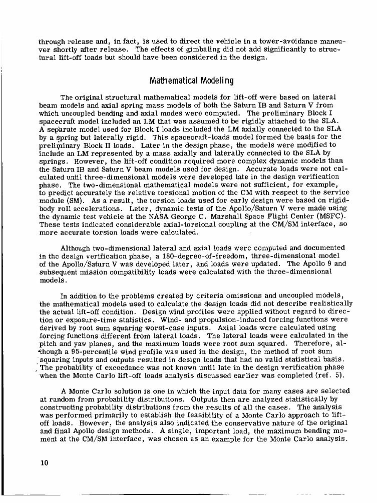
through release and, in fact, is used to direct the vehicle in a tower-avoidance maneu- ver shortly after release. The effects of gimbaling did not add significantly to struc- tural lift-off loads but should have been considered i n the design.
Mathematical Modeling
The original structural mathematical models for lift-off were based on lateral beam models and axial spring mass models of both the Saturn IB and Saturn V from which uncoupled bending and axial modes were computed. The preliminary Block I spacecraft model included an LM that was assumed to be rigidly attached to the SLA. A sep'arate model used for Block I loads included the LM axially connected to the SLA by a spring but laterally rigid. This spacecraft-loads model formed the basis fo r the preli$inary Block I1 loads. Later in the design phase, the models were modified to include an LM represented by a mass axially and laterally connected to the SLA by springs. However, the lift-off condition required more complex dynamic models than the Saturn IB and Saturn V beam models used for design. Accurate loads were not cal- culated until three-dimensional models were developed late in the design verification phase. The two-dimensional mathematical models were not sufficient, for example, to predict accurately the relative torsional motion of the CM with respect to the service module (SM). As a result, the torsion loads used for early design were based on rigid- body roll accelerations. Later, dynamic tes ts of the Apollo/Saturn V were made using the dynamic test vehicle at the NASA George C. Marshall Space Flight Center (MSFC). These tests indicated considerable axial-torsional coupling at the CM/SM interface, so more accurate torsion loads were calculated.
Although two-dimensional lateral and axial I_oad,c were zompiiied ana documented
of the Apollo/Saturn V was developed la ter , and loads were updated. The Apollo 9 and subsequent mission compatibility loads were calculated with the three-dimensional models.
qn :.. thq b A ~ ~ wzaigii cl------ verification phase, a 180-degree-of-freedom, three-dimensional model
In addition to the problems created by cr i ter ia omissions and uncoupled models, the mathematical models used to calculate the design loads did not describe realistically the actual lift-off condition. Design wind profiles were applied without regard to direc- tion or exposure-time statistics. Wind- and propulsion-induced forcing functions were derived by root sum squaring worst-case inputs. Axial loads were calculated using forcing functions different from lateral loads. The lateral loads were calculated in the pitch and yaw planes, and the maximum loads were root sum squared. Therefore, al- *though a 95-percentile wind profile was used in the design, the method of root sum 'squaring inputs and outputs resulted in design loads that had no valid statistical basis. The probability of exceedance w a s not known until late in the design verification phase when the Monte Carlo lift-off loads analysis discussed earlier was completed (ref. 5).
A Monte Carlo solution is one in which the input data fo r many cases a r e selected at random from probability distributions. Outputs then a r e analyzed statistically by constructing probability distributions from the resul ts of all the cases. The analysis was performed primarily to establish the feasibility of a Monte Carlo approach to lift- off loads. However, the analysis also indicated the conservative nature of the original and final Apollo design methods. A single, important load, the maximum bending mo- ment at the CM/SM interface, was chosen as an example fo r the Monte Carlo analysis.
10

A moment obtained by the Apollo design method of root sum squaring the maximum mo- ments from three cases was compared with the Monte Carlo result . Each of the three cases was constructed from the selection of 30 wind, unsymmetrical thrust, and thrust misalinement forcing functions. Probability distributions of these data were prepared, and 200 independent se t s of forcing functions were selected for the Monte Carlo analy- sis. A compilation of the maximum CM/SM interface moment from all cases estab- lished a log-normal distribution. The CM/SM bending moment obtained by the root-sum-square method (the design moment) was never exceeded in the 200 Monte Carlo cases and would not be expected to be exceeded at least 99.99 percent of the time. This example indicates the potentially conservative nature of a lift-off design load ob- tained by the root sum square of several discrete cases derived from worst-case in- put forcing functions.
Another load source overlooked in the initial Apollo design phase was that result- ing from a conditioning and inerting purge of the SM and SLA. The purge increases the SM and SLA internal pressure and, therefore, increases the CM/SM interface tension loads at lift-off. The purge pressure was reflected in the structural capability analysis.
INFLIGHT WIND RESPONSE
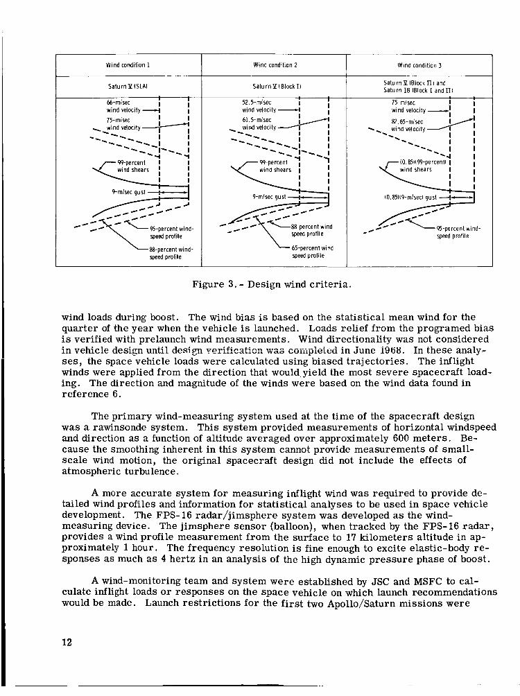
The inflight wind response period extends from the time the lift-off transients damp out until the end of first-stage boost. The original design cr i ter ia specified that the vehicle must withstand the winds associated with the 95-percentile idealized scalar windspeed profile envelope, windspeed changes (wind shear) for altitude differentials to 10 000 feet (the 99-percentile windspeed changes), and a discrete quasi-square-wave gust (29.5 ft/sec) superimposed on the windspeed change so that the maximum wind- speed did not exceed the idealized windspeed profile. A wind profile constructed to these cr i ter ia is shown in figure 3. These wind cr i ter ia were to be applied to the vehi- cle from any horizontal direction during boost.
Vehicle loads for this wind condition were determined using constant aerodynamic and inertial coefficients and included the effects of two elastic modes. An evaluation was made of the interpretation of the inflight wind-condition cr i ter ia , and an agreement was reached that the applied gust should be in excess of the 95-percentile windspeed envelope. When this change was implemented and its severity evaluated, a statistical combination of the wind shear and wind gust was applied. The effect of this statistical combination was approximated by a 15-percent reduction of the wind shears and wind- gust magnitude. The result of this change also is indicated in figure 3.
Inflight wind-loads cr i ter ia and analysis did not include the effects of turbulence, propellant slosh, wind direction, thrust oscillations, loads-minimization methods through trajectory shaping, gust penetration, higher frequency modes, and time-varying coefficients. Several of these effects significantly influence loads analysis. The most important effects not included in the design are wind directionality and biasing of the command-pitch program in operational trajectories to reduce space vehicle loads. Only the first Apollo mission did not involve the use of wind biasing for load relief. For the first mission, the pitch program was biased to induce loads into the space ve- hicle and to tes t the vehicle structure. Subsequent to this mission, the decision w a s made to take advantage of the biasing technique and to attempt to reduce the inflight
11
Wind condition 1
SaturnP ISLAI
I I 66-mlsec wind velocity -c( I
I I I -I I I I I -- - % I I
-4 -I
75-mlsec ,%wind velocity
\ --- %%%
--\ I-%% I
99-percent
9-mlsec aust : I
speed profile
88-percen t wind- speed profile
Wind condition 2
Satu rn Y ( BI ock II
I I 52.5-mlsec I
wind velocity 4 I 61.5-mlsec
% wind velocity I I
%%%% %- -% I I -%%---I I -- I-%- I
wind shears I
I
/
speed profile
65-percent wind- speed profile
Wind condition 3
SaturnP (Block II) and Saturn IB (Block I and Ul
Figure 3. - Design wind cr i ter ia .
wind loads during boost. The wind bias is based on the statistical mean wind for the quarter of the year when the vehicle is launched. Loads relief from the programed bias is verified with prelaunch wind measurements. Wind directionality w a s not considered in vehicle design until design verificatio:: was CGiiipleieci in June 1988. In these analy- ses, the space vehicle loads were calculated using biased trajectories. The inflight winds were applied from the direction that would yield the most severe spacecraft load- ing. The direction and magnitude of the winds were based on the wind data found in reference 6.
The primary wind-measuring system used at the time of the spacecraft design was a rawinsonde system. This system provided measurements of horizontal windspeed and direction a s a function of altitude averaged over approximately 600 meters . Be- cause the smoothing inherent in this system cannot provide measurements of small- scale wind motion, the original spacecraft design did not include the effects of atmospheric turbulence.
A more accurate system for measuring inflight wind was required to provide de- tailed wind profiles and information for statistical analyses to be used in space vehicle development. The FPS- 16 radar/jimsphere system was developed as the wind- measuring device. The jimsphere sensor (balloon), when tracked by the FPS-16 radar , provides a wind profile measurement f rom the surface to 17 kilometers altitude in ap- proximately 1 hour. The frequency resolution is fine enough to excite elastic-body re- sponses as much as 4 hertz in an analysis of the high dynamic pressure phase of boost.
A wind-monitoring team and system were established by JSC and MSFC to cal- culate inflight loads o r responses on the space vehicle on which launch recommendations would be made. Launch restrictions for the first two Apollo/Saturn missions were
12

based on angle-of-attack dynamic-pressure a q limits that were proportional to the vehicle design loads. The a q for these missions w a s predicted using measured rawin- sonde data from the launch site. The predicted aq history was compared with the a q allowable, and a recommendation was made to launch based on this comparison. This method of monitoring inflight winds did not include the effects of elastic-body response; variations in axial load; nonlinear aerodynamics; propellant slosh; and variation in q caused by winds, turbulence, thrust oscillations, and gust penetration.
Beginning with the AS-201 mission, a new method was used to calculate spacecraft interface loads for comparison with structural allowables (fig. 4). The launch recom- mendation could be made on the basis of this comparison. The FPS-16/jimsphere data from this measurement system were put into a vehicle flight-simulation program for load calculation. In this operational procedure, the wind measurements and flight-loads simulations were begun 24 hours before launch and repeated periodically until launch. This procedure gave a history of the winds and vehicle loads that provided the basis of operational assurance during the actual launch. The flight-loads simulations for both spacecraft and launch vehicle on the Apollo 4 to 10 missions were conducted by a joint JSC/MSFC monitoring team at MSFC. These simulations included the effects missing in the a q restrictions, with the exception of propellant slosh. The elastic-body defini- tion was restricted to two modes.
Because the FPS- 16/jimsphere data measured before launch were transmitted from the launch complex at KSC to JSC and MSFC, a JSC flight-loads simulation that gave better definition of spacecraft loads was initiated for loads calculation to make the launch recommendation. A JSC flight simulation for inflight wind monitoring was im- plemented on the Apollo 11 mission and has been used on all subsequent missions. This simulation includes the effects of four elastic-body bending modes and all the effects missing in the a q restrictions except for fuel slosh.
Using the wind-biasing technique, inflight wind loads for the Apollo missions have been well below design values for all but the first mission, which was biased deliber- ately to increase the vehicle loads for a structural test. When the relieving pitch-plane bias is considered, the design condition for the inflight wind condition is overly conserv- ative. The effects of wind biasing should be considered in the definition of the inflight wind condition for all future programs.
Several assessments of cri teria for the inflight wind condition have been completed using the wind data measured by the FPS- 16/jimsphere system. King and Ryan (ref. 7) made a comparison of maximum space vehicle loads resulting from the idealized syn- thetic wind profile to loads resulting from a large sample of jimsphere wind profiles. Although the maximum spacecraft loads from the two wind descriptions were of the same magnitude, the most severe spacecraft loading w a s in response to a high-turbulence wind profile, the maximum wind velocity of which was 26 m/sec compared with the 82.65 m/sec of the design criteria. This result indicates that, for highly flexible vehi- cles, the influence of wind turbulence may be of equal or greater importance than the high-wind shear and the high-wind magnitude and should be included in future inflight winds response conditions.
TO combine rationally the effect of winds, propellant slosh, thrust oscillations, and trajectory shaping in new vehicle design, a Monte Carlo analysis of boost is recom- mended. As discussed for the lift-off case, a Monte Carlo solution is one in which input
13

4 Structural model Engine and
actuator model
- - - - - - - - - - - - - -
Final wind- I Vehicle dynamics data edit
i
Z 6 % 50
- 0
- O r -
s;g100
'p E X I c L -
10 20 30 40 50 60 70 80 W 100 2 Flight time, sec
Figure 4. - Prelaunch simulation for inflight wind loads.
Elastic-body simulation
\nalysis
Launch complex
launch or no launch because of excessive winds
data for many cases a r e selected at random f rom pfobability distributions. For boost, probability distributions would be defined for all vehicle parameters, such as thrust oscillations, and the vehicle would be flown, by flight-loads simulation, through a large number of measured FPS- 16/jimsphere wind profiles. Using results from these boost simulations, a statistical analysis could be made of vehicle structural loads; this analy- sis would be the basis of design loads fo r the space vehicle.
14

CONCLUDING REMARKS AND RECOMMENDATIONS
Several conclusions can be made concerning the wind load design conditions of the Apollo Program. The prelaunch design conditions did not account for the following ef- fects that could be cri t ical to vehicle loading: exposure periods, turbulence, crawler operation, vehicle propellant loadings , on-pad vehicle configurations, auxiliary damp- ing, and wind direction. The ground wind-tunnel tests were conducted too late in the program to support the original design of the spacecraft. The Apollo design cr i ter ia and analyses for lift-off were not realistic because they did not consider accurately the effects of unsymmetrical thrust buildup, on-pad purging, wind direction and exposure periods, realistic description of vortex shedding, realistic representation of thrust misalinement, and three-dimensional structural dynamics. A Monte Carlo analysis showed that the root-sum-square method of combining loads for lift-off was overly con- servative and created design loads for which the probability of occurrence is unknown.
The evolution from wind measurement to load measurement as a primary ground- wind monitoring system improved the Apollo operational capability by incorporating measured vehicle dynamics rather than assuming the existence of conservative levels. The inclusion of a biased pitch program in the space vehicle operations was significantly different f rom the design condition and resulted in an overly conservative inflight wind- response design condition. By analysis, inflight winds of high turbulence and low mag- nitude have been shown to cause loads as severe as the loads resulting from the design synthetic wind profile; therefore, the original wind cr i ter ia were not adequate to ac- count for the effects of turbulence.
Emphasis should be placed on realistic cri teria and analysis of the design wind loads; therefore, six recommendations are made.
1. New programs should include exposure periods, turbulence, propellant load and pressurization variations, on-pad maintenance configurations , crawler operations, and loads-alleviation methods in the design prelaunch condition. These were not con- sidered i n the Apollo design.
2. Wind-tunnel ground-wind testing should be initiated early in the program to allow test resul ts to influence vehicle design.
3. The future design phase for lift-off should include development of a statistical load analysis to provide realistic design conditions and greater operational capability.
4. Provisions for a wind-monitoring procedure that provides the maximum op- erational capability consistent with a safe launch should be included as early as possible in the design of new vehicles.
5. In future programs, the space vehicle loads relief for all conditions should be included in the design as well as in the operational portion of the vehicle life.
15

6. A Monte Carlo analysis is recommended to define a more rational inflight wind design condition. In such an analysis, the new vehicle could be flown, by flight-loads simulation, through a large number of measured FPS- 16/jimsphere wind profiles, and a statistical analysis could be made using the results of these simulations.
Lyndon B. Johnson Space Center National Aeronautics and Space Administration
Houston, Texas, March 27, 1973 914-50-20-14-72
REFERENCES
1. Daniels, Glenn E. : Terrestr ia l Environment (Climatic) Criteria Guidelines for Use i n Space Vehicle Development. NASA TM X-53023, 1964.
2. Kaufman, J. W . ; and Keene, L. F. : NASA's 150-Meter Meteorological Tower Located a t the Kennedy Space Center, Florida. NASA TM X-53699, 1968.
3 . Daniels, Glenn E. : Terrestr ia l Environment (Climatic) Criteria Guidelines for Use in Space Vehicle Development, 1969 Revision. NASA TM X-53872, 1969.
4 . Den Hartog, J. P. : Mechanical Vibrations. Fourth ed . , McGraw-Hill Book Co. , Inc . , 1956.
5. Schwartz, Robert D. : Monte Cir lc ha lys i s sf Sti-iiztiii-iil Luads Eesuiting From Space Vehicle Lift-off. NASA TM X-58046, 1970.
6 . Daniels, Glenn E. ; Scoggins, James R. ; and Smith, Orvel E. : Terres t r ia l En- vironment (Climatic) Criteria Guidelines for U s e in Space Vehicle Development, 1966 Revision. NASA TM X-53328, 1966.
7. King, A. W. ; and Ryan, R. S . : The Influential Aspects of Atmospheric Disturb- ances on Space Vehicle Design Using Statistical Approaches for Analysis. NASA TM X-53565, 1967.
16