E4014 Construction Surveying Route Location Surveys Reconnaissance Survey Investigation Survey...
29
E4014 Construction Surveying Route Location Surveys Reconnaissance Survey Investigation Survey Working Survey Construction Survey
-
date post
22-Dec-2015 -
Category
Documents
-
view
248 -
download
1
Transcript of E4014 Construction Surveying Route Location Surveys Reconnaissance Survey Investigation Survey...

E4014 Construction Surveying
Route Location SurveysReconnaissance SurveyInvestigation SurveyWorking SurveyConstruction Survey

Reconnaissance Survey
Gather sufficient information to select one or more bands of country for the possible route
• Assemble basic information– Topographic maps– Cadastral maps / GIS– Aerial photos– Orthophotos

Reconnaissance Survey
• Evaluate
– General topography – Geology– Meteorological statistics– Flood records– Unsuitable terrain– Land use and ownership / Local
Authority’s GIS– Existing services– Existing communications

Reconnaissance Survey
• Field reconnaissance to confirm assembled data
• Choose possible routes
• NOTIFY RELEVANT AUTHORITIES
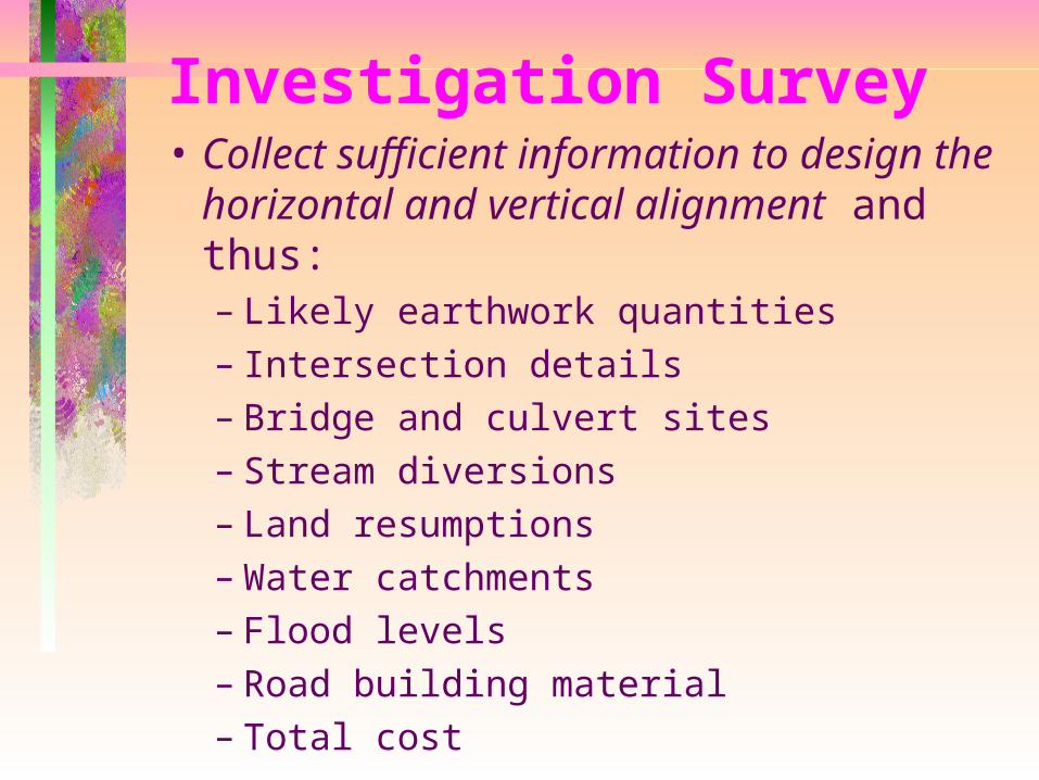
Investigation Survey• Collect sufficient information to
design the horizontal and vertical alignment and thus:– Likely earthwork quantities– Intersection details– Bridge and culvert sites– Stream diversions– Land resumptions– Water catchments– Flood levels– Road building material– Total cost
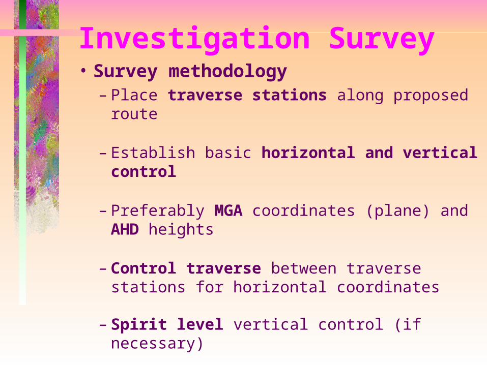
Investigation Survey• Survey methodology
– Place traverse stations along proposed route
– Establish basic horizontal and vertical control
– Preferably MGA coordinates (plane) and AHD heights
– Control traverse between traverse stations for horizontal coordinates
– Spirit level vertical control (if necessary)

Investigation Survey• Survey methodology, cont
– Create a DTM either by cross sections or point pickup• level & staff• total station• GPS
– 200m band (100m ether side of proposed centreline) or as requested

Investigation Survey• Survey methodology, cont
– include• railway / tramway• road and bridge details• culverts• overhead cables, transmission lines,
heights• underground services• cadastral boundaries and fences• property improvements• geological features and soil types• vegetation• watercourses and swamps

Investigation Survey• Survey methodology, cont
– Accuracy• Horizontal 1 : 5000
• Vertical ( 0.012 K) metres– where K is the distance levelled in kilometres
Investigation Survey• Survey methodology, cont
– Catchment Areas• Necessary for bridge and culvert design
• Aerial photos
• Compass and clinometer traverses

Investigation Survey• Survey methodology, cont
– Aerial Surveys• May be utilised in lieu of other methods
• Photographed data becomes a reasonably permanent record, unbiased and complete
• Heights are not necessarily accurate

Working Survey• A working survey must provide
data of sufficient accuracy and extent for the satisfactory detailed design of the road and the later setting-out for construction.

Working Survey• Survey Marks
– Pegs (75mm * 50mm) are placed along the centre line (straight and curves) at 20 / 50 metre intervals
– Offsets (75mm * 50mm pegs, short star pickets driven flush) placed left and right of centre line • 200 metre intervals• beginning, centre and end of curves
– level and check level all centre line and offset pegs

Working Survey• Survey Marks, cont
– establish benchmarks • at 1km intervals• at bridge and culvert sites

Working Survey• DTM is established at the following
widths
– Secondary roads 15 metres left and right
– Main roads 25 metres left and right
– Developmental roads and highways30 metres left and
right

Working Survey• Detail (horizontal and vertical)
– located within 100 metres of the centre line
– All public and private improvements
– Existing road and rail formations
– Drainage
– Underground and overhead services

Working Survey• Bridge and culvert sites
– Require sufficient information to plot 0.25 metre contours for 100 metres up and down stream of the centre line
– Grid may be used• Lines parallel and at 3 metres intervals from the
centre line• Each line is levelled from high bank to high bank• Any intermediate section where the profile
changes is also levelled
– Bed levels for 500 metres up and down stream
– Sections taken at the end and at any profile changes

Working Survey• Watershed traverses
– as per Investigation Survey
• Working drawings– Plan
– Long-section
– Cross-sections

CONSTRUCTION SURVEY
urban equivalent to the Working Survey
• route is pre-determined by the presence of existing road reserves
• general survey requirements are the same as for Working Surveys
• density of detail is such that the procedures of observation and recording may have to be varied

CONSTRUCTION SURVEY• Separate field and level books
should be used– Detail Files / Field Notes
• (i) Main centreline pegging and adjacent detail
• (ii) Subsidiary centreline pegging and detail
• (iii) Fence traverses to locate dividing fences and property improvements
• (iv) Side street centreline traverses

CONSTRUCTION SURVEY• Separate field and level books
should be used– Level Notes
• (i) Main centreline levels and normal cross section
• (ii) Subsidiary centreline levels• (iii) Check levels• (iv) Drainage levels, both
underground and surface• (v) Subsidiary levels - accesses• (vi) Side street levels and cross-
sections• (vii) Side street check levels

CONSTRUCTION SURVEY• With respect to field books, cross
referencing of information and explanations of abbreviations used require utmost care and attention
• same code table used by all surveyors
• planning with the aid of maps should ensure that no area remains unsurveyed

CONSTRUCTION SURVEY• Centre Line
– unable to safely mark the centreline of roads already carrying high loads of traffic
– centreline pegged along one footpath parallel to road centreline where possible
– subsidiary line along opposite footpath, if necessary
– offset pegs placed in "safe positions" eg against fences
CONSTRUCTION SURVEY• Centre Line, cont
– fences
– detail may be located chainage & offset as well as radiations
– houses, dividing fences, points of vehicular access, etc. may be located by "chainage & offset" along previously located fence lines

CONSTRUCTION SURVEY• Cross Sections
– based on main centre line – normally extend 5 metres into adjacent
properties– if resumptions are anticipated then cross
sections may have to be extended– be aware of abrupt changes in level
between footpath and adjacent properties
– must illustrate the true cross section shape of the road (ie crown, changes of cross fall, edges, channel lips, channels, kerbs and footpath)

CONSTRUCTION SURVEY• Subsidiary Cross Sections
– required at all vehicular accesses to adjacent properties
– extend 5 metres into adjacent property

CONSTRUCTION SURVEY• Drainage Detail
– both open and underground
– underground • position and level of manhole or pit
• size and direction of all pipes, leading in and out
• invert levels on all pipes

CONSTRUCTION SURVEY• Drainage Detail, cont
– open drainage• channels and natural watercourses as per
culverts sites in Working Survey
– watershed• difficult to determine in urban situation
• attention must be paid to the position and direction of flow in stormwater pipes near the natural watershed boundary

CONSTRUCTION SURVEY• side streets
– extend minimum of 50 metres