E3 ELECTRIC CURRENT - University of Sydney School … E3 ELECTRIC CURRENT OBJECTIVES! Aims By the...
14
27 E3 ELECTRIC CURRENT OBJECTIVES Aims By the time you have finished with this chapter you should have a good understanding of the nature of electric current and its effects, including the processes of energy transfer and mass transfer. You should also understand the concepts, such as resistance, resistivity and conductivity used to describe the properties of materials, called conductors, which can carry current. Minimum learning goals When you have finished studying this chapter you should be able to do all of the following. 1. Explain, interpret and use the terms: conductor, current, ampere, current density, charge carrier, number density, drift velocity, degree of ionisation, mass transfer rate, source, load, electric power, V-I characteristic, resistance, ohm, conductance, siemens, Ohm's law, resistivity, conductivity. 2. Describe the principal effects of electric currents and ways of measuring currents. 3. State, apply and discuss the equation relating current density to particle densities, charges and drift velocities of charge carriers and explain how the signs of the charge carriers are related to the direction of the current. 4. Give examples of typical magnitudes of current density in engineering and biological applications. 5. Describe and discuss how mass transfers are associated with electric currents. State and apply expressions for mass flow rate in terms of current and the masses and charges of the carriers. 6. State and explain the meaning of Ohm's law for objects and materials. 7. Discuss, explain and apply the relations among current density, electric field, conductivity, resistivity, the dimensions of conducting bodies and resistance. 8. Describe and calculate power transfers in terms of voltage and current. CONCEPT DIAGRAM Current and current density Mass transfers associated with currents Power transfers mediated by currents Continuity of current and methods of measurement Voltage, current resistance, conductance Electrolysis Examples: x-ray tube, lamp Biological applications Electric field & current density Conductivity and resistiviy
-
Upload
truongdang -
Category
Documents
-
view
217 -
download
2
Transcript of E3 ELECTRIC CURRENT - University of Sydney School … E3 ELECTRIC CURRENT OBJECTIVES! Aims By the...

27
E3 ELECTRIC CURRENT
OBJECTIVES!AimsBy the time you have finished with this chapter you should have a good understanding of the natureof electric current and its effects, including the processes of energy transfer and mass transfer. Youshould also understand the concepts, such as resistance, resistivity and conductivity used to describethe properties of materials, called conductors, which can carry current.
Minimum learning goalsWhen you have finished studying this chapter you should be able to do all of the following.1. Explain, interpret and use the terms:
conductor, current, ampere, current density, charge carrier, number density, drift velocity,degree of ionisation, mass transfer rate, source, load, electric power, V-I characteristic,resistance, ohm, conductance, siemens, Ohm's law, resistivity, conductivity.
2. Describe the principal effects of electric currents and ways of measuring currents.3. State, apply and discuss the equation relating current density to particle densities, charges and
drift velocities of charge carriers and explain how the signs of the charge carriers are related tothe direction of the current.
4. Give examples of typical magnitudes of current density in engineering and biologicalapplications.
5. Describe and discuss how mass transfers are associated with electric currents. State and applyexpressions for mass flow rate in terms of current and the masses and charges of the carriers.
6. State and explain the meaning of Ohm's law for objects and materials.7. Discuss, explain and apply the relations among current density, electric field, conductivity,
resistivity, the dimensions of conducting bodies and resistance.8. Describe and calculate power transfers in terms of voltage and current.
CONCEPT DIAGRAMCurrent and
current density
Mass transfersassociated
with currents
Power transfersmediated by
currents
Continuity of currentand methods ofmeasurement
Voltage, currentresistance,
conductance
Electrolysis Examples:x-ray tube, lamp
Biological applications
Electric field & current density
Conductivity and resistiviy

28
PRE-LECTURE!3-1 THE NATURE OF ELECTRIC CURRENTAn electric current can be broadly defined as charged particles in motion - a flow of charge. Themost obvious effect of a current would seem to be the transfer of charge from one place to another.So it is, when a charged body is discharged by touching it with an earthed wire, or when lightningstrikes a tree. However, it is important to realise that most currents flow in closed loops or circuitswith no net transfer of charge. When there is a steady current the distribution of charge around acircuit remains constant and every part of the circuit remains substantially neutral.
The effects of electric currentYou can't see anything move in an electric current but currents do have a number of extremelyimportant effects, which can be broadly classified as shown in the first column of table 3.1. This listis by no means exhaustive. Some of the topics are discussed in later chapters. In this chapter we areconcerned in general terms with the charge, mass and energy transferred by a current.
Effect Applications Measuring devicesHeating Electric room heater Measure i2
Magnetic Electromagnet Clip-on ammeterElectrolysis Aluminium smelting Measure Ú Idt
Electrochemical Kolbe's synthesis of ethane -Biological Cardiac defibrillation -
Mechanical (throughmagnetism)
Moving coil meterElectric motorLoudspeakers
Deflection of a coil
Emission of light Lamp filamentFluorescent light
Light emitting diode.
-
Voltage drop(potential difference)
Digital ammeter Measure voltage across aknown resistor
Table 3.1 Effects of electric current
The measurement of electric currentElectric current is measured by means of a device which responds quantitatively to one or other ofthe effects of the current. Because current is a flow of charge, the device usually has to be connectedso that the current goes through it. The most important effects used in measuring current are listedin the third column of table 3.1.
Each system has advantages and disadvantages. The choice is determined by the exigencies ofthe situation. For example a clip-on ammeter does not require the interruption of the current, but it isbulky and not very sensitive. By contrast a digital ammeter responds quickly. Moving coil metershave the advantage of simplicity and long-term stability.
QuestionsQ3 .1 To what extent is the flow of water analogous to the flow of charge? What are the hydrodynamic
analogues of (a) current, (b) potential difference, (c) resistance? Which of the effects of a current are alsoshown by flowing water?
Q3.2 When do you think it might be appropriate to use a current meter based ona) the heating effectb) electrolysis?
Give your reasons.

E3: Electric current 29
LECTURE!3-2 ELECTRIC CURRENT AND CHARGE CARRIERS
Movement of chargeAny movement of charge constitutes an electric current. The charge carriers could be electrons in avacuum, electrons in a metal, 'holes' in a semiconductor or ions in a solution. The charge may movein free space, through a conductor or on a conveyor belt. An obvious manifestation of chargemovement is an electric spark. At each spark some charge is transferred. Together a sequence ofsparks makes up an intermittent current in which each spark contributes a current pulse. If the sparkgap is narrowed so that the sparks become more frequent, they tend to merge to make a continuouscurrent.
Definition and unit of currentThe value of a current in a wire at any point is defined to be equal to the rate of flow of net positivecharge past that point. The direction of the current is defined to be the direction of flow of positivecharge.
If the charge carriers are actuallynegative then the direction of the current isopposite to the flow direction of the particles.Thus a current of one ampere to the right infigure 3.1 could be either positive chargeflowing to the right at 1 coulomb per secondor negative charge flowing to the left at 1coulomb per second, or some combination offlows in both directions such 0.5 C.s-1 eachway. Figure 3.1 Equivalent currents
The SI unit of electric current is the ampere (symbol A), equal to one coulomb per second.Because current is easier to measure than charge, the physical standards have been established usingcurrent as the base quantity, so the coulomb is defined as an ampere-second (A.s). The ampere isdefined in terms of magnetic effects (see chapter E6).
Kinds of currentThe simplest kind of current is that carried by a beam of electrons through a vacuum. For example,in a typical TV tube (figure 3.2), the flow rate of electrons from the electron gun to the screen isabout 6 ¥ 1013 electrons per second. Since each electron has a charge of -1.6 ¥ 10-19 C, the beamcurrent is about 10 µA from the screen to the electron gun.
Hot filament
Electronemittingelectrode
Accelerating andfocussing electrodes
Electron beam
+V 1 2 +V 3 +V
Figure 3.2 An electron gunThis one is electrostatically focussed. Many devices, including electron microscopes, use magnetic
focussing

30
Similarly, in wires the positive charges on the ions of the crystal lattice remain fixed, while thecurrent is carried by the drift of the negatively charged electrons. Where confusion might arise youmust distinguish between the direction of electron movement and the direction of the conventionalcurrent.
Why didn't we avoid this confusion about current direction by calling the electron's chargepositive? The answer goes back to Benjamin Franklin who thought he could see which way chargewas flowing in sparks. His choice established the definitions of positive and negative in electricity.
In conducting materials only a small fraction of all the electrons is free to move and carrycurrent. The majority are too strongly bound to the respective nuclei. In p-type silicon (and othersemiconductors) the number of mobile electrons is just less than the number of positive ions in thecrystalline lattice of the material. The result is that when there is a current the mobile electrons play asort of musical chairs, hopping from one vacant point in the lattice to the next. The overall effect canbe described as a net flow of positive holes. Transistors and other semiconductor devices dependfor their operation on simultaneous conduction by electrons and holes.
Electron moves right
Hole moves left
Result
Figure 3.3 Conduction by positive holesAn electron, in the 2nd row and 2nd column, jumps into a vacant atomic site, moving from left to
right. This is equivalent to saying that the hole moves to the left. The equivalent current is to the left.
3-3 CURRENT DENSITY
Definition and examplesA current in a bulk material is described in terms of the current density, that is the current percross-sectional area of the material. To see what that means think of a small imaginary surface, witharea ∆A, inside the material, oriented at right angles to the direction of the current (figure 3.4). Write∆I for the current through the surface. The magnitude of the current density, averaged over thesurface, is defined as
j =DIDA . ... (3.1)
If the little surface is allowed to shrink, the average current density approaches a limiting value whichis the current density at a point in the material. We need to think of the current density as a vectorquantity because we associate direction with currents. So current density is a vector quantity definedat all points in the material - it is a vector field. It varies in magnitude and direction throughout abody and it can also be mapped in the same way as the electric field by drawing lines of currentdensity which show the direction of the current at each point in the material. In fact, unless thematerial is a superconductor, current cannot exist without an electric field and the directions of theelectric field and the current density must be the same at every point.
Rain often carries current. In this instance the charge carriers are raindrops. In a typicalstorm, the current carried to each square meter of ground may be 0.1 µA. This is expressed bysaying that the current density in rain is 0.1 µA.m-2. By contrast, the current densities through themembranes of living cells are in the region of 1 A.m-2. Electric power conductors carry currentdensities of the order of 0.1 GA.m-2.

E3: Electric current 31
.
∆A
∆Ij
Figure 3.4 Current and current density
Theory: current density and charge flowThe current density in a material depends on the density of the charge carriers and their averagevelocity at each place. The particles which carry current in a material - electrons or ions - arecontinually moving at high speeds, typically some hundreds of metres per second, but if there is nocurrent they don't actually go anywhere on average. They are continually colliding and bouncing offeach other and other particles, so they are just as likely to be moving in one direction as in any other.Their average velocity, averaged over all the charge carriers and any reasonable time interval, is zero.When a current exists, the charge carriers still rush around madly, but between collisions theyacquire a little extra velocity in a definite direction - parallel to the electric field if they are positiveand antiparallel if they are negative. This extra component of velocity is called drift velocity.Surprisingly perhaps, drift velocities are quite small, typically some fraction of a millimetre persecond. What we think of as large currents are large because they involve a huge number of chargecarriers.
We might expect that current density j should increase if we could increase any of the threequantities, the number density of charge carriers (number per volume, n), the charge on each carrier(q) and the magnitude of the drift velocity ( v ). In fact it is given by the product of all three which isthe only combination, apart from a possible numerical factor, that gives the correct units:
j = nqv . ... (3.2)The same result can be worked out more formally by finding the rate at which the charge
carriers go through a small imaginary surface of area A (represented by the white area in figure 3.5).In a short time interval dt all those carriers which are within a distance v d t of the surface will getthrough. The number of particles is the number within the volume Av d t , that is a total of nAv d tparticles. They carry a total charge of qnAv d t . To find the current divide the charge by the timeinterval: I = nqvA . Finally, divide by the area to get equation 3.2.
Thickness
Velocity ofcharge carriers
AArea
vd t
Av d tVolume
v
Figure 3.5 Current density and drift velocity

32
In electrolytes, ionised gases, living cells and so on there will in general be more than one typeof charge carrier, and each will contribute a term to the current density. For two carrier types,
j = n1q1v1 + n2q2v2 ... (3.2a)
(Note that j, v1 and v2 are vector quantities. If there is only one kind of carrier then the currentdensity vector has the same direction as the drift velocity of positive charge carriers.)
Figure 3.6 A current of moving positive and negative carriersIn this diagram, the positive carriers drift to the right and the negative carriers drift to the left. Both sets
of carriers contribute to the current to the right
Demonstration: Practical application of current as an analogue of water flowThe flow of charge is analogous to the flow of fluids. In the video lecture, Professor Collis-George demonstrates how this analogy is put to practical use. Current in electrically conductingpaper is used to predict patterns of water flow in proposed soil drainage systems.
The conducting paper is cut to the shape of the region through which the water will flow,and metal electrodes are placed on this paper to represent the ditches through which the waterflows, into and away from this region. The positions of several points on a specificequipotential are located with a probe attached to a voltmeter, and this equipotential is drawn.Further equipotentials between the electrodes are drawn in this manner, and give the waterisobars within the irrigated soil. The electric current is in the direction of the electric field.Thus, by drawing lines perpendicular to these equipotentials (isobars) 'streamlines' are obtainedwhich show the pattern of the current between the electrodes.
By using this model we can obtain the water pressure within the soil, the pattern of waterflow, and even the total volume of water that flows through the soil. Thus the effectiveness ofan irrigation system can be checked without the effort of digging ditches or of measuring thewater pressure profile in the irrigated region.
IonsSince we usually consider the charge carriers to be either electrons or ions we can express theircharges as multiples of the electronic charge e; q = ze. The integer z is called the degree ofionisation. So for example an electron has q = -e, and a doubly ionised positive ion such as copper(Cu++) has q = 2e.
3-4 ELECTRIC CURRENT AND FLOW OF MASSNot only is electric current analogous to fluid flow: all charge carriers have mass, so a mass flow isnecessarily involved in any electric current. Of course, in some circumstances the net mass flowmay be zero (how?). Electric current is sometimes used to produce a mass flow.
E3: Electric current 33
DemonstrationAn example explained in the video lecture is the vacuum coating of glass with copper by theprocess of sputtering. This is one stage in the production of one type of solar energy collector.It works as follows.
A heavy current of argon ions is established in a vacuum tube. Since the ions havemass, the current carries energy and momentum. The ions strike a copper electrode withsufficient kinetic energy to dislodge a stream of copper atoms which fly through the vacuum andcoat the collector tube with copper.
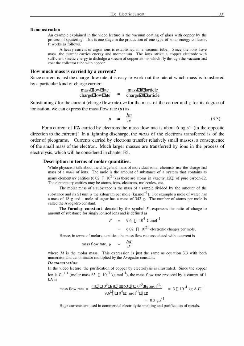
How much mass is carried by a current?Since current is just the charge flow rate, it is easy to work out the rate at which mass is transferredby a particular kind of charge carrier:
mass"flow"ratecharge"flow"rate =
mass"of"particlecharge"of"particle
Substituting I for the current (charge flow rate), m for the mass of the carrier and z for its degree ofionisation, we can express the mass flow rate (µ) as
µ =Imze . ... (3.3)
For a current of 1"A carried by electrons the mass flow rate is about 6 ng.s-1 (in the oppositedirection to the current)! In a lightning discharge, the mass of the electrons transferred is of theorder of picograms. Currents carried by electrons transfer relatively small masses, a consequenceof the small mass of the electron. Much larger masses are transferred by ions in the process ofelectrolysis, which will be considered in chapter E5.
Description in terms of molar quantities.While physicists talk about the charge and mass of individual ions, chemists use the charge andmass of a mole of ions. The mole is the amount of substance of a system that contains asmany elementary entities (6.02 ¥ 1023) as there are atoms in exactly 12"g of pure carbon-12.The elementary entities may be atoms, ions, electrons, molecules, etc.
The molar mass of a substance is the mass of a sample divided by the amount of thesubstance and its SI unit is the kilogram per mole (kg.mol-1). For example a mole of water hasa mass of 18 g and a mole of sugar has a mass of 342 g. The number of atoms per mole iscalled the Avogadro constant.
The Faraday constant, denoted by the symbol F , expresses the ratio of charge toamount of substance for singly ionised ions and is defined as
F = 9.6 ¥ 104 C.mol-1
= 6.02 ¥ 1023 electronic charges per mole.Hence, in terms of molar quantities, the mass flow rate associated with a current is
mass flow rate, µ = IMzF
where M is the molar mass. This expression is just the same as equation 3.3 with bothnumerator and denominator multiplied by the Avogadro constant.DemonstrationIn the video lecture, the purification of copper by electrolysis is illustrated. Since the copperion is Cu++ (molar mass 63 ¥ 10-3 kg.mol-1), the mass flow rate produced by a current of 1kA is
mass flow rate = (1"¥ "103"A) "¥ " " (63 "¥ "10-3"kg.mol-1)9.6" ¥ "104"C.mol-1"¥ " 2
= 3 ¥ 10-4 kg.A.C-1
= 0.3 g.s-1.Huge currents are used in commercial electrolytic smelting and purification of metals.

34
3-5 CURRENT AND ENERGY FLOW
Current and energy transferWhen there is an electric current in a circuit, energy is generally being transferred from a source toa load: energy is transferred from a battery to a lamp or from a nerve cell to measuring electrodes.In such circuits, the current is associated with the energy transfer.
Source Load
Current
Current
Energy flow
Figure 3.7 The transfer of energy in a simple circuit
The charge flows continuously round the circuit, from source to load and back again. Theenergy flows from source to load. From this it is clear that the current is not the energy, but issimply associated with transfer of energy. (In rather the same way a bicycle chain is the means bywhich muscle energy is transferred from the crank to the wheel.)
The intermediate step in conveying energy from the source to the load is electric potentialenergy. The electrons gain potential energy in the battery, and lose this potential energy in the load.
If the source were connected to an evacuated tube such as a cathode ray tube this potentialenergy would be converted to the kinetic energy of the electrons.
When a source is connected to a lamp (or any other resistive load) electric potential energy isalso given to the charge carriers (electrons) by the source. However as they go round the circuit theyalmost immediately start to lose energy in collisions with the ions which make up the crystallinestructure of the conducting metal. This lost energy causes the material to heat up, even to the extentthat it emits light.
Demonstration: Rolling marbles model of currentIn the marble model of a simple circuit demonstrated in the video lecture, the muscle energyexpended in raising the gravitational potential energy of the marbles corresponds to the chemicalenergy expended by a battery in raising the electrical potential energy of electrons.
Initially, as they roll down the ramp, the marbles gain kinetic energy that is equivalent tothe gravitational potential energy they lose. This is almost immediately lost in collisions withthe pegs on the ramp, appearing as sound and internal energy. A marble rolling down the rampgains, on the average, as much kinetic energy between collisions as it loses per collision.
Notice that there is not much potential drop across the supply and return ramps. Theseramps represent the low resistance wires connecting the source to the load.
Electric power (= rate of energy transfer)
+
-
q
q V L
´
Figure 3.8 Power transfer in a circuit
Consider a charge q which flows once round the circuit shown in figure 3.8. The EMF of thesource is ´. When a charge q traverses the circuit, it gains energy +´q as it goes through the battery(source) and loses energy +VLq (as light and heat) when it passes through the load. Usually these

E3: Electric current 35
energies are almost equal as there is little energy lost in the connecting wires. (Energy is conserved:the energy gained in the source is equal to the energy lost in the load and connecting wires.)
If there is a continuous current I, the power delivered (i.e. the rate at which energy isdelivered) by the source is
Ps = ddt( )´q = e dq
dt = eI .
Similarly the power consumed by the load isPL = VLI .
In general, for any component the power transferred is the product of the voltage across it with thecurrent through it:
P = VI . ... (3.4)
3-6 RESISTANCE AND RESISTIVITY
Measurement of V-I characteristicsThe relationship between the current through an object and the potential difference across it can beexplored experimentally by varying the applied voltage and plotting a graph of V against I.
DemonstrationIn the video lecture, an X-Y chart plotter is used to plot such graphs quickly.
Adjustablesource Sample
To"voltage"terminals of plotter
To "current" terminalsof plotter
A
A'
Figure 3.9 Apparatus for plotting V-I graphs
The variable voltage V across the sample deflects the pen in the Y direction (in this particularexperiment -5 V < V < 5 V) and the corresponding current I deflects the pen in the X direction(-100 mA < I < +100 mA). Thus at any time the pen position records both V and I. Byadjusting the variable voltage supply, a graph of V against I is automatically plotted for thedevice or sample connected at AA'. Graphs were thus plotted for a coil of copper wire, a smalllamp and a semiconductor diode with the results shown in figure 3.10.
I
V light globe
diode
copper wire
Figure 3.10 V-I graphs for a wire, a lamp and a diode

36
For the copper wire, the V-I characteristic was a straight line of uniform slope. The slope ofthe line is equal to the resistance, R, of the sample
R =VI = constant ... (3.5)
An object which is a poor conductor has a high resistance. An alternative way of describing theconducting ability of an object is to specify is conductance G which is defined simply as thereciprocal of resistance. One advantage of the idea of conductance is that it gives sense to the rule forcombining electrical objects connected in parallel; parallel paths conduct better so you just addconductances.
The SI unit of resistance is the volt per ampere, which has the special name, ohm, (symbol Ω).The unit of conductance is the siemens (S), which is equivalent to a reciprocal ohm.
Ohm's lawOhm's law states that for many substances, over a wide range of conditions, the resistance of anobject is constant, as it was for the copper wire sample. The copper wire sample is said to obeyOhm's law. However, the lamp and the diode do not obey Ohm's law.
The lamp had a low resistance (small V/I) at first (i.e. small applied voltage). However as thecurrent increased, the voltage increased more rapidly. As the lamp heated up, its resistance increased,as evidenced by the increasing slope of the graph. (Note: Ohm's law generally applies to metals atconstant temperature.)
The diode is another example of a non-ohmic device. The resistance change is not now dueto a temperature change; in fact the diode is an almost perfect 'one way' device. For positive voltagesabove about 0.5 V, the resistance (V/I) is very low, and the diode is an excellent conductor. Forvoltages of the opposite polarity, the resistance is very high: the diode hardly conducts at all. Noticethat we still talk about the resistance of non-ohmic devices. The difference is that the resistance isnot constant, but varies with current. For such devices, the resistance read by an ohmmeter willdepend on the current used in making the measurement.
Application to bulk materials: resistivity and conductivitySo far we have discussed the resistance of samples or devices. For bulk materials, it is morepertinent to look at what is happening inside the material, in terms of current density and whatdetermines its value. It has been noted already that at each point in the material the current dependson the electric field and is in the same direction as the field. Except for superconductors, no field, nocurrent. The relation between field and current density can be defined as:
j = gE . ... (3.6)Here g represents a property of the material called its conductivity. (Note: some books use thesymbol s for conductivity, but we have already used that symbol for surface charge density.)Equation 3.6 does not imply that current density is proportional to field, the conductivity could, andoften does, depend on the field. However it is a constant for some for some materials when they areheld at constant temperature. They are the same materials which obey Ohm's law, so saying that g isconstant is stating that Ohm's law applies. It is often convenient to use the property resistivity, rwhich is just the reciprocal of conductivity:
r =1g =
Ej ... (3.7).
Remember that conductivity and resistivity are properties of a material rather than an objectwith a particular shape. The SI units are siemens per metre (S.m-1) for conductivity and ohm metre(Ω.m) for resistivity. Table 3.2 gives the resistivities and conductivities of a few common materials.
Substance r / (Ω.m) g / (S.m- 1)

E3: Electric current 37
Copper 1.6 ¥ 10-8 6 ¥ 107
Living tissue 0.2 5Pyrex glass ~ 1014 ~ 10-14
Distilled water 102 to 105 10-5 to 10-2
Fused quartz > 1014 < 10-14
Table 3.2 Some typical conductivities and resistivities
Resistivity, resistance and sample shapeThe resistance of an object depends on the materials used to make it, its size, its shape and the placeswhere connect on to it. The last point is important. A given object can many different values ofresistance, because the current you get depends not only on the voltage applied but also on the placeswhere you let the current in and out. Calculating the resistance of a particular arrangement could bea daunting task, but there is one simple case that is easy to do, and is quite useful. It requires aspecimen which has a uniform cross section and electrical connections to the two ends which admitthe current uniformly over the end faces. (A metal coating whose conductivity is much higher thanthat of the object, spread over each end would do the trick.)
So consider a sample of uniform cross-sectional area A and length l. A current I passesthrough the sample as shown in figure 3.11, and the corresponding potential difference between itsends is V.
Area, A I
I
V j , E l
Figure 3.11 Measurement of resistivity
Provided the current density is uniform, its magnitude is given by
j =IA
and the electric field (parallel to j) has a magnitude
E =Vl .
Now in the material, E = r j ;hence, substituting for E and j we obtain:
Vl = r
IA .
38
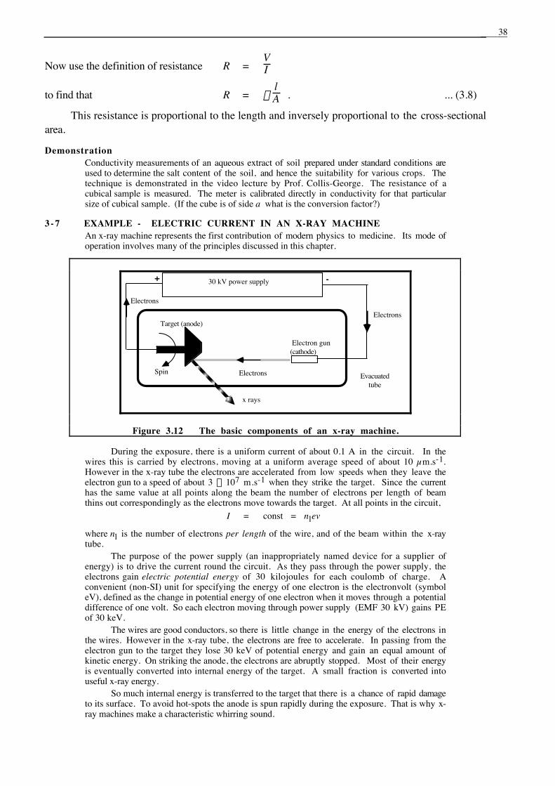
Now use the definition of resistance R =VI
to find that R = r lA . ... (3.8)
This resistance is proportional to the length and inversely proportional to the cross-sectionalarea.
DemonstrationConductivity measurements of an aqueous extract of soil prepared under standard conditions areused to determine the salt content of the soil, and hence the suitability for various crops. Thetechnique is demonstrated in the video lecture by Prof. Collis-George. The resistance of acubical sample is measured. The meter is calibrated directly in conductivity for that particularsize of cubical sample. (If the cube is of side a what is the conversion factor?)
3 - 7 EXAMPLE - ELECTRIC CURRENT IN AN X-RAY MACHINEAn x-ray machine represents the first contribution of modern physics to medicine. Its mode ofoperation involves many of the principles discussed in this chapter.
x rays
30 kV power supply
Target (anode)
Electron gun(cathode)
Electrons Evacuatedtube
Electrons
Electrons
+ -
Spin
Figure 3.12 The basic components of an x-ray machine.
During the exposure, there is a uniform current of about 0.1 A in the circuit. In thewires this is carried by electrons, moving at a uniform average speed of about 10 µm.s-1.However in the x-ray tube the electrons are accelerated from low speeds when they leave theelectron gun to a speed of about 3 ¥ 107 m.s-1 when they strike the target. Since the currenthas the same value at all points along the beam the number of electrons per length of beamthins out correspondingly as the electrons move towards the target. At all points in the circuit,
I = const = nlev
where nl is the number of electrons per length of the wire, and of the beam within the x-raytube.
The purpose of the power supply (an inappropriately named device for a supplier ofenergy) is to drive the current round the circuit. As they pass through the power supply, theelectrons gain electric potential energy of 30 kilojoules for each coulomb of charge. Aconvenient (non-SI) unit for specifying the energy of one electron is the electronvolt (symboleV), defined as the change in potential energy of one electron when it moves through a potentialdifference of one volt. So each electron moving through power supply (EMF 30 kV) gains PEof 30 keV.
The wires are good conductors, so there is little change in the energy of the electrons inthe wires. However in the x-ray tube, the electrons are free to accelerate. In passing from theelectron gun to the target they lose 30 keV of potential energy and gain an equal amount ofkinetic energy. On striking the anode, the electrons are abruptly stopped. Most of their energyis eventually converted into internal energy of the target. A small fraction is converted intouseful x-ray energy.
So much internal energy is transferred to the target that there is a chance of rapid damageto its surface. To avoid hot-spots the anode is spun rapidly during the exposure. That is why x-ray machines make a characteristic whirring sound.
E3: Electric current 39
POST-LECTURE!
3-8 CORRECT USE OF ELECTRICAL TERMINOLOGYProfessor Bragg Snr of the University of Adelaide is reputed to have once asked his class, ‘who cantell me just what electricity is?’ and received the reply, ‘I did once know, sir, but I've forgotten’.‘What a tragedy for Mankind’, said Bragg, ‘the only person who ever knew what electricity was hasforgotten!’
Electricity is mysterious. You can't see or weigh it. It needs curious unnatural machinery togenerate it. It does all sorts of extraordinary things. This perceptual mystery of electricity is noexcuse for failure to understand and use correctly the few technical terms used in descriptions ofelectricity. Expressions such as ‘the resistance caused a high amperage across the battery’ and ‘itmust have had a lot of volts through it’ are not only quite meaningless; they reveal a profoundmisunderstanding of basic physical ideas involved. Unfortunately such misuse of electricalterminology is all too common.
Here are a few terms and ideas which you must thoroughly understand.• Electric current is the flow of charge. It is measured by inserting an ammeter in series with the
circuit. There is no such word as amperage. The term is current and its unit is ampere.• Potential difference is defined in chapter E2. It is analogous to pressure difference and is
measured by connecting a voltmeter between the two points of interest. Usage permits us touse the technician's term 'voltage' for potential difference. The unit of potential difference isvolt.
• The SI unit of power is the watt (but power is not called wattage). Electric power = potentialdifference ¥ current.
• The SI unit of energy is the joule. A joule is a watt second, or alternatively a watt is a joule persecond. For reasons of convenience, electrical energy is sometimes measured in kilowatthours: 1 kW.h = 3.6 MJ.
• The resistance of a component is the ratio of the potential difference across the terminals to thecurrent in the component. The SI unit of resistance is volt per ampere which has the specialname of ohm. There is no such word as 'ohmage'.
3-9 QUESTIONSQ3.3 If electrical energy costs 18 c for each kW.h, what would it cost to raise a house of mass 500 tonnes a
height of 1 m above the ground, using an electric motor of 50% efficiency?Q3.4 a ) Sketch an x-ray tube and label the electron gun and anode. Indicate the polarity of the accelerating voltage,
the direction of electron flow and the direction of the current.b) Consider an x-ray exposure of 0.10 s with a beam current of 0.20 A and an accelerating voltage of
30"kV. What charge is transferred during the exposure? How many electrons strike the anode?c) How much mass is transferred during the exposure?d) At what rate does the power supply deliver energy during the exposure?e) How much energy is released in the exposure?f) Calculate the speed and energy of each electron just before it strikes the anode.g) Why is the anode of an x-ray tube spun during the exposure? Roughly how fast should the anode spin
in terms of the exposure time?

40
Q3.5 In an experiment to measure the membrane potential of a living plant cell, micro-electrodes are placedinside and outside the cell. Making the measurement produces a current of 1.5 nA through the membranefrom the exterior to the interior of the cell. The total area of the cell membrane is 1.0 mm2. Calculate thecurrent density in the membrane produced by the measurement.
If the current is carried through the membrane equally by chloride ions Cl- and sodium ions Na+,calculate the flow of mass of each ion species during the measurement, and the number of ions transferredin a measurement lasting 30 s.
Mass of a Cl- ion = 5.9 ¥ 10-26 kg.
Mass of a Na+ ion = 3.8 ¥ 10-26 kg.
Q3.6 In a storm, falling raindrops carry a current density of 1.0 ¥ 10-6 A.m-2 towards the ground. If 100 dropsstrike each square meter of ground per second, calculate the magnitude and sign of the average charge oneach raindrop.
Q3.7 In a copper (Cu++) electrolysis tank, what mass of copper is deposited by a current of 10 kA in 10minutes?
Mass of Cu++ ion = 1.1 ¥ 10-25 kg.
Q3.8 A laboratory maintains a group of animal houses which are heated electrically by radiators with a combinedcapacity of 100 kW. The radiators are controlled by thermostats. On average, the radiators are on about50% of the time in the four coldest months, and about 10% of the time during the rest of the year. Ifelectrical energy costs 18 cents per kW.h, what is the annual cost of heating the animal houses?
Q 3 . 9 a) A research assistant has been making measurements of voltage and current on a sample of livingmaterial, and presents you with the following data:
Voltage/V Current/µA3.0 1502.0 1101.0 45
What can you deduce about the resistance of the specimen from these data? What, in your view,is the most serious deficiency in your assistant's work?
b) A more experienced assistant finds by experiment that the relationship between current and voltage for adifferent specimen can be expressed as
V = aI + b I2
where a = 70 V.A-1 and b = 2.0 ¥ 103 V.A-2.In addition to the resistance, physicists often use a quantity called dynamic resistance to describe the
properties of an object like this one. The dynamic resistance is defined as the rate of change of voltagewith respect to current which can be found from the slope of a V-I graph, rather than the usual ratio V/I..To avoid confusion the usual resistance can then be referred to as the static resistance. What are the staticresistance and the dynamic resistance for this object at a current of 10 mA?
Q3.10 An aqueous extract of a particular soil is placed in a glass tube of internal diameter 5.0 mm and length0.64"m. The resistance between the ends of this column of extract is 2.15 kΩ. Calculate the resistivityand the conductivity of the solution.
Q3.11 Given that current density in a material must depend on the number density of charge carriers, the charge oneach one and their drift velocity, show that apart from an unknown numerical factor, equation 3.2 is theonly one that balances the units correctly.