
E230 Aircraft Systems - Yola - ShareIt!resourcer.yolasite.com/resources/E230-S13.pdf · E230...
24
E230 Aircraft Systems One Fantastic Landing 6th Presentation School Of Engineering
Transcript of E230 Aircraft Systems - Yola - ShareIt!resourcer.yolasite.com/resources/E230-S13.pdf · E230...

E230 Aircraft Systems
One Fantastic Landing
6th Presentation School Of
Engineering

School of Engineering
Landing Gear - Purpose
• To provide a support for
the plane when at rest
on the ground,
• To provide a stable
chassis for taxiing,
braking or rolling during
take-off and landing
• To provide a shock
absorbing system during
landing.
Antonov 225 Main Landing Gears http://www.youtube.com/watch?v=x9HHfnNr1cg

School of Engineering
Landing Gear Systems
• Strut
• Shock Absorber
• Extension / Retraction
Mechanism
• Brakes
• Wheel
• Tires

School of Engineering
Landing Gear Configurations
Tail-wheel (or Tail-dragger Gear ) versus Tricycle (or Nosewheel Gear )
Advantage Disadvantage
Simplistic in design Poor handling characteristics
Shorten the runaway distance for
take-off or landing
Higher chance of a "ground loop“
as CG behind main wheel axis
Operate the aircraft over rough
field operation or terrain
Poor pilot visibility during taxiing
and it is more difficult to land
Large clearance between the
propeller tips and the ground for
propeller-driven planes.
Difficult to load or unload heavy
cargos and for passengers due to
the steep slope of the cabin floor
Advantage Disadvantage
Better visibility over the nose, thus
easier to taxi and steer.
Greater weight and drag incurred by
adding the large nose wheel strut
Parallel thrust of the engine to the
direction of travel, hence allowing
faster acceleration during take-off.
Usually require complex retraction
mechanisms to reduce drag. Add weight
to aircraft.
More stable during take-off, landing
and taxiing as CG in front of main
wheel axis. Reduce “ground loop”
effect.
Need to perform weight and balance
calculation periodically to ensure weight
distribution for braking effectiveness
School of Engineering
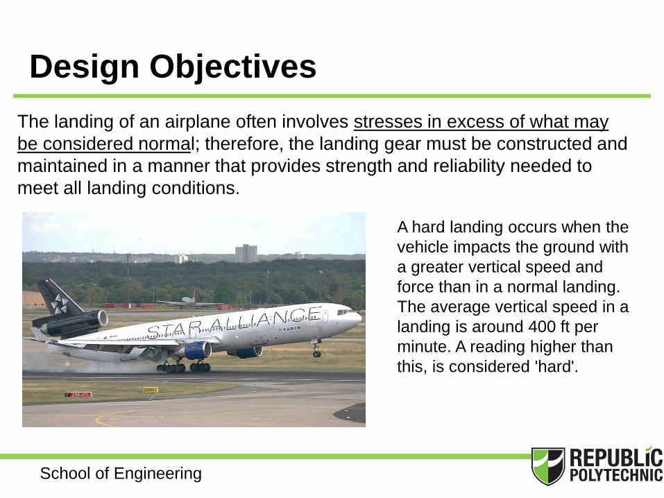
Design Objectives
The landing of an airplane often involves stresses in excess of what may
be considered normal; therefore, the landing gear must be constructed and
maintained in a manner that provides strength and reliability needed to
meet all landing conditions.
A hard landing occurs when the
vehicle impacts the ground with
a greater vertical speed and
force than in a normal landing.
The average vertical speed in a
landing is around 400 ft per
minute. A reading higher than
this, is considered 'hard'.

School of Engineering
Design Considerations
• Each landing gear designs or configurations has its own advantages
and disadvantages. Selecting the best arrangement for a given
aircraft depends on the environment and purpose the plane is
designed for.
• In spite of all these design considerations and variations, designers
will always try to select the simplest, lightest, and least expensive
solution possible to fulfil the objectives while maintaining safety.

School of Engineering
Classification of Landing Gears
1. Non-Absorbing Landing Gear and
Fixed Gear
– Includes rigid landing gear, shock-cord
landing gear, spring landing gear
– Rigid: helicopters, sailplanes.
– Usually non-retractable, Light weight, less
complex
2. Shock-Absorbing Landing Gear
– Dissipates landing energies by forcing fluid
through
a restriction
– Air-Oil Oleo most common nowadays.
– Usually retractable by hydraulic, electric or
mechanical to eliminate drag during flight

School of Engineering
Main Landing Gear Components
The main landing gear is
designed to support and to
stabilize the assembly itself.
The terms used for the landing
gears may vary according to
manufacturers.
School of Engineering
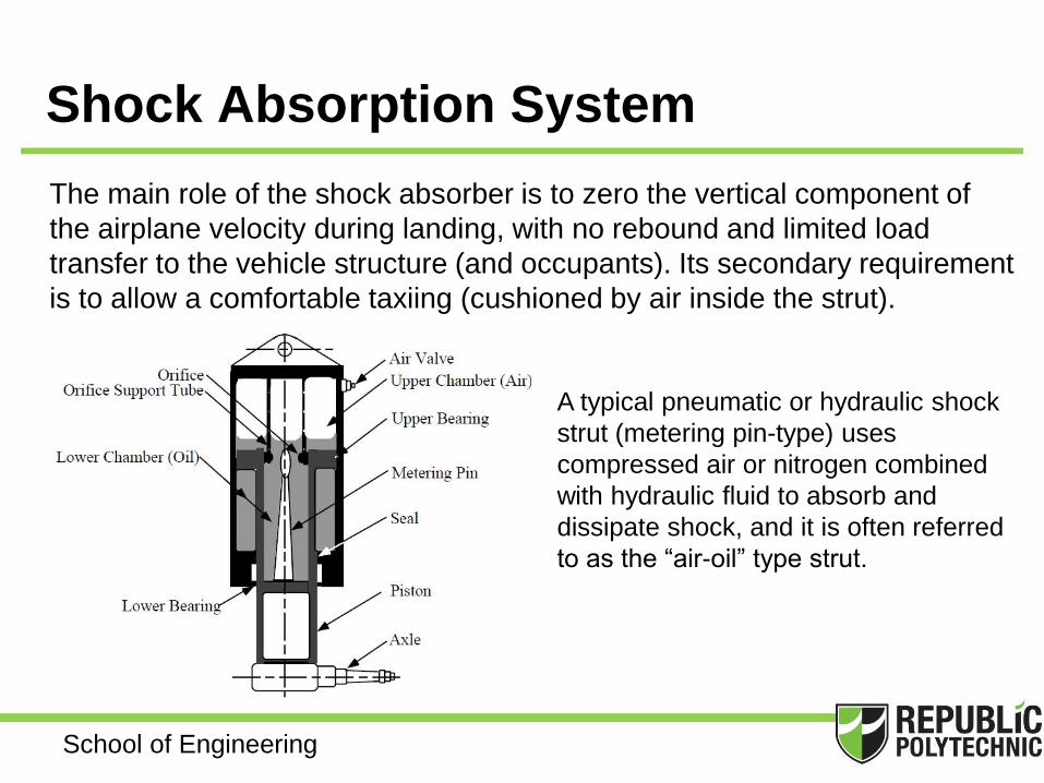
Shock Absorption System
The main role of the shock absorber is to zero the vertical component of
the airplane velocity during landing, with no rebound and limited load
transfer to the vehicle structure (and occupants). Its secondary requirement
is to allow a comfortable taxiing (cushioned by air inside the strut).
A typical pneumatic or hydraulic shock
strut (metering pin-type) uses
compressed air or nitrogen combined
with hydraulic fluid to absorb and
dissipate shock, and it is often referred
to as the “air-oil” type strut.

School of Engineering
Nose Landing Gear Steering Systems
• For light aircraft, steering by rudder (yaw effect) or by differential braking
that involves applying the brakes to the left or right wheels as required to
turn the aircraft.
• For large transport aircraft, steering achieved using hydraulically assisted
systems as followed -
Rack and Pinion
Rotary Actuator
Push-Pull Actuator
Multiplying Linkage

School of Engineering
Nose Landing Gear Features
Centering Cam A centering cam or a centering
spring may be used to ensure that
the gear is centered prior to
retraction. This is facilitate
disconnection of various elements
involved
Shimmy Damper Wheel is said to shimmy when it
oscillates about its caster axis. A
shimmy damper is a hydraulic
snubbing unit that reduces the
tendency of the nose wheel to
oscillate from side to side.

School of Engineering
Retraction and Extension Systems
A retractable landing gear is installed whenever a drag improvement is
worthy. Landing gear extension is a primary operation and always its
actuation has high redundancy. There are different solutions and various
systems for the mechanism to obtain suitable landing gear movement.
These include
• Mechanical and/or Electrical Systems
Crank mechanism or uses a lever pulled by the pilot
Use a mechanical latch system to lock wheels “up”
Uses a central electric motor and push-pull rods to open/close
doors and position the gear.
Uses micro-switches to detect when gear position.
For light aircraft only

School of Engineering
Retraction and Extension Systems
• Hydraulic Systems
Used where landing gear is
considered too large or
economically not viable by other
methods Hydraulic power generated by
engine-driven pumps, electric
pumps. For emergency operation, hand or
wind-driven pumps Most common system of retraction
for larger aircraft types.
Testing for the Boeing 787 Dreamliner. Gear swing tests
replicate the extension and retraction of the landing gear, as
they would function on a regular flight. Successfully swinging
the landing gear into a stowed position and back down into a
landing position verifies the installation and functionality are
working as expected

School of Engineering
Emergency Extension Systems
There are four possible methods of dropping or extending gear when hydraulic
power is lost:
• Using air bottle to “blows” the gear down.
Substituting air pressure for hydraulic pressure.
• Operation of a hand crank or ratchet
extends the gear.
• Separate and backup hydraulic system
(may be hand pump)
• Mechanical system which releases Up-locks,
thus allowing gear free-fall into the down-and-lock
position. Mechanism should be designed in such a way that gravity
and aerodynamic drag favours extension with no power from the
hydraulic system.

School of Engineering
Position Indications and Warnings
It is imperative that the flight crew has a absolute indication of the gear position and
status. The following features or mechanism will help determine that -
• Squat Switches are switches operated by the extension and compression of
the landing gear struts. When the gear struts is compressed, the switches are
“open” and an electrically operated lock prevents the raising of the gear, and
vice versus.
• Aural Warning Horns and Indicator Lights When
the gear is in retracted position and the aircraft is at
landing speed, the aural warning and indication lights
will warn the pilot that the gear is not in the “Down”
position (GPWS related).
http://www.meriweather.com/320/fd-320.html

School of Engineering
Wheels & Brakes
The tires and wheels of an aircraft are subjected to severe stresses during
landing and in taxiing over round ground. The failure of a tire or wheel can
lead to extremely serious accident.
For that, it is vital that tires and wheels inspected and monitored for its
condition for all environments under which the aircraft may operate.

School of Engineering
Tires (Tyres)
Tires are the aircraft-to-ground interface and subjected to braking and steering
forces. They also contribute in a minor extent to shock absorption. Tires for aircraft
must endure higher loads and higher speeds than automobiles and trucks; the safety
issue is much higher as well.
Practically all modern aircraft tires are tubeless. The external layer in contact with the
ground is the treaded, and made from rubber (similar to automotive tire, but much
thicker).
School of Engineering
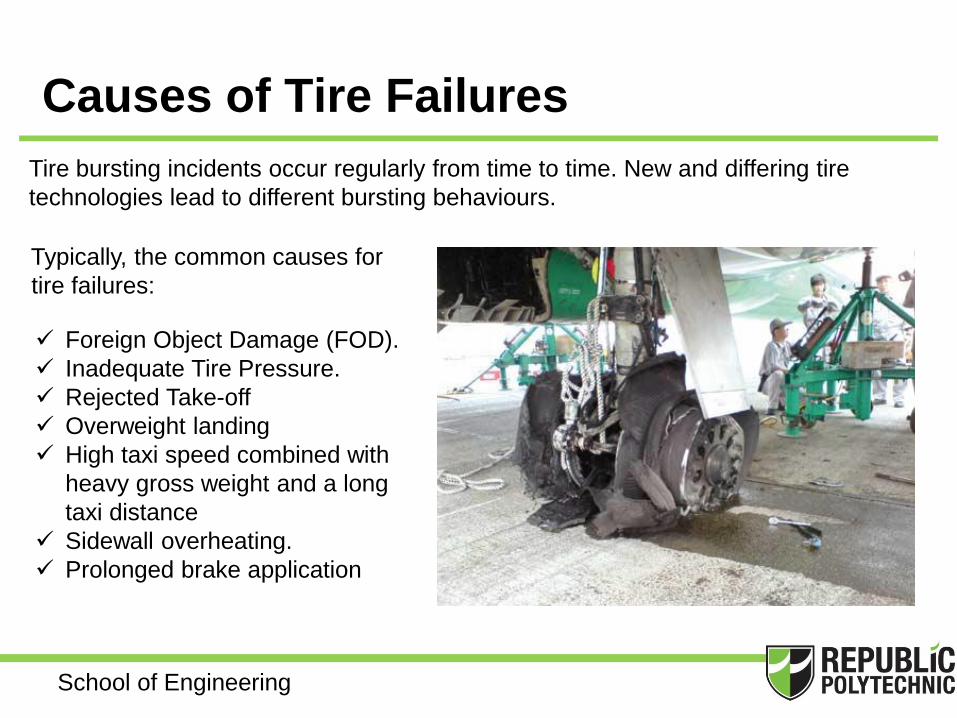
Causes of Tire Failures
Tire bursting incidents occur regularly from time to time. New and differing tire
technologies lead to different bursting behaviours.
Typically, the common causes for
tire failures:
Foreign Object Damage (FOD).
Inadequate Tire Pressure.
Rejected Take-off
Overweight landing
High taxi speed combined with
heavy gross weight and a long
taxi distance
Sidewall overheating.
Prolonged brake application
School of Engineering
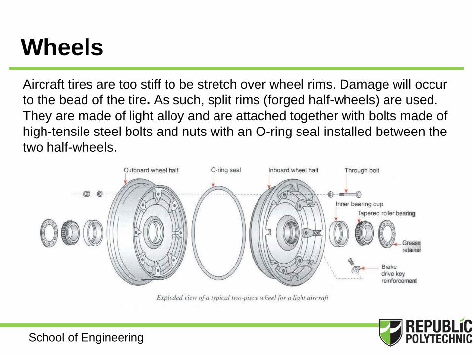
Wheels
Aircraft tires are too stiff to be stretch over wheel rims. Damage will occur
to the bead of the tire. As such, split rims (forged half-wheels) are used.
They are made of light alloy and are attached together with bolts made of
high-tensile steel bolts and nuts with an O-ring seal installed between the
two half-wheels.

School of Engineering
Wheels Fusible Plugs
High performance aircraft have one or more
fusible plugs in the inbound wheel half.
These plugs have a hole drilled through their
center filled with a low melting point alloy.
In the event of an aborted take-off or other
emergency braking, so much heat is
produced in the brakes that the air in the tires
tries to expand, resulting in a pressure rise
so high the wheel could explode. To prevent
this, the center of the fusible plugs melts and
deflates the tires in a few seconds when the
wheel reaches a dangerous temperature.

School of Engineering
Brakes
Most airplanes are equipped with disc
brakes, with a functioning principle similar
to that of the automotive systems, but
based on different sizing principles.
The various brake designs to reflect the
variety of braking capabilities required for
different-sized aircraft. Light aircraft can
rely on a single disc brake or simple shoe
brake because the landing speed is slow
and the aircraft is light in weight.
Large transport aircraft land at high speeds
and weight several hundred tons. Such
aircraft require very powerful multi-surfaced
brakes in order for the brakes to be
effective at slowing down the aircraft.
MD-11 Brake cut-out half-side

School of Engineering
Types of Brakes
Two basic types of brakes are in use,
energizing (E) and non-energizing (NE).
Energizing brakes use the friction developed
between rotation and stationary parts to
produce a wedging action. Non-energizing
brakes does not use this wedging action.
Some of the various brake designs are
as follow:
• Drum-type servo brakes (E)
• Expander tube brakes (NE)
• Single-disk brakes (NE)
• Multiple-disk brakes (NE)
• Segmented rotor disk brakes (NE)

School of Engineering
Anti-Skid System
Aircraft are usually equipped with anti-skid systems to prevent of
aircraft control on the ground by skidding of the wheels. Several
reasons apply why anti-skid systems are in use on many modern
aircraft:
A good anti-skid system will have
two main features: Wheel sensors
that can detect a change in the
rate of deceleration and a valve
system that can rapidly released
and apply, which will prevent a
skid
• Prevents wheel lockup
• Prevents skidding
• Reduce possibility of hydroplaning
• Reduce excessive heat build up

School of Engineering
Learning Objectives
• Understand the functions and design considerations of a
landing gears system.
• Identify the various landing gear configurations
• Understand features of a Nose Landing Gears.
• Identify and understand the various functions and
features of other peripherals components of a landing
gear major components (i.e. tire, wheels, brakes)