E1.1 Analysis of Circuits - Imperial College London · 2017-10-17 · • Buy the textbook: Hayt,...
72
E1.1 Analysis of Circuits (2017-10213) Introduction: 1 – 1 / 16 E1.1 Analysis of Circuits Mike Brookes
Transcript of E1.1 Analysis of Circuits - Imperial College London · 2017-10-17 · • Buy the textbook: Hayt,...

E1.1 Analysis of Circuits (2017-10213) Introduction: 1 – 1 / 16
E1.1 Analysis of Circuits
Mike Brookes
1: Introduction
1: Introduction
• Organization
• What are circuits?
• Circuit Diagrams
• Charge
• Current
• Potential Energy
• Voltage
• Resistors +
• Cause and Effect
• Resistor Power Dissipation
• Voltage and CurrentSources
• Power Conservation
• Units and Multipliers
• Summary
E1.1 Analysis of Circuits (2017-10213) Introduction: 1 – 2 / 16

Organization
1: Introduction
• Organization
• What are circuits?
• Circuit Diagrams
• Charge
• Current
• Potential Energy
• Voltage
• Resistors +
• Cause and Effect
• Resistor Power Dissipation
• Voltage and CurrentSources
• Power Conservation
• Units and Multipliers
• Summary
E1.1 Analysis of Circuits (2017-10213) Introduction: 1 – 3 / 16
• 18 lectures: feel free to ask questions
• Buy the textbook: Hayt, Kemmerly & Durbin “Engineering CircuitAnalysis” ISBN: 0071217066 (£44) or Irwin, Nelms & Patnaik“Engineering Circuit Analysis” ISBN: 1118960637 (£37)
• Weekly study group: Problem sheets - KEEP UP TO DATE
• Fortnightly tutorial: tutorial problems
• Lecture slides (including animations) and problem sheets + answersavailable via Blackboard or from my website:http://www.ee.ic.ac.uk/hp/staff/dmb/courses/ccts1/ccts1.htm
Quite dense: you should understand every word
• Email me with any errors or confusions in slides or problems/answers
• Christmas Test in January
• Exam in June (sample papers + solutions available via Blackboard)

What are circuits?
1: Introduction
• Organization
• What are circuits?
• Circuit Diagrams
• Charge
• Current
• Potential Energy
• Voltage
• Resistors +
• Cause and Effect
• Resistor Power Dissipation
• Voltage and CurrentSources
• Power Conservation
• Units and Multipliers
• Summary
E1.1 Analysis of Circuits (2017-10213) Introduction: 1 – 4 / 16
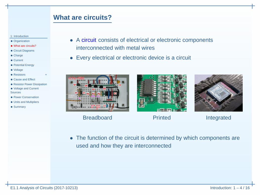
• A circuit consists of electrical or electronic componentsinterconnected with metal wires
• Every electrical or electronic device is a circuit

What are circuits?
1: Introduction
• Organization
• What are circuits?
• Circuit Diagrams
• Charge
• Current
• Potential Energy
• Voltage
• Resistors +
• Cause and Effect
• Resistor Power Dissipation
• Voltage and CurrentSources
• Power Conservation
• Units and Multipliers
• Summary
E1.1 Analysis of Circuits (2017-10213) Introduction: 1 – 4 / 16
• A circuit consists of electrical or electronic componentsinterconnected with metal wires
• Every electrical or electronic device is a circuit
Breadboard Printed Integrated
• The function of the circuit is determined by which components areused and how they are interconnected

What are circuits?
1: Introduction
• Organization
• What are circuits?
• Circuit Diagrams
• Charge
• Current
• Potential Energy
• Voltage
• Resistors +
• Cause and Effect
• Resistor Power Dissipation
• Voltage and CurrentSources
• Power Conservation
• Units and Multipliers
• Summary
E1.1 Analysis of Circuits (2017-10213) Introduction: 1 – 4 / 16
• A circuit consists of electrical or electronic componentsinterconnected with metal wires
• Every electrical or electronic device is a circuit
Breadboard Printed Integrated
• The function of the circuit is determined by which components areused and how they are interconnected: the physical positioning ofthe components usually has hardly any effect.

Circuit Diagrams
1: Introduction
• Organization
• What are circuits?
• Circuit Diagrams
• Charge
• Current
• Potential Energy
• Voltage
• Resistors +
• Cause and Effect
• Resistor Power Dissipation
• Voltage and CurrentSources
• Power Conservation
• Units and Multipliers
• Summary
E1.1 Analysis of Circuits (2017-10213) Introduction: 1 – 5 / 16
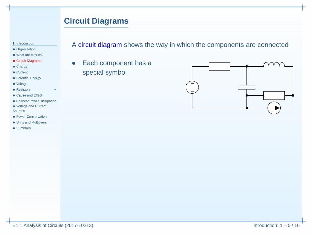
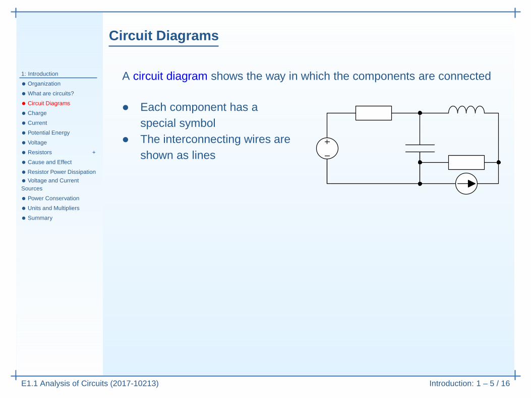
A circuit diagram shows the way in which the components are connected
Circuit Diagrams
1: Introduction
• Organization
• What are circuits?
• Circuit Diagrams
• Charge
• Current
• Potential Energy
• Voltage
• Resistors +
• Cause and Effect
• Resistor Power Dissipation
• Voltage and CurrentSources
• Power Conservation
• Units and Multipliers
• Summary
E1.1 Analysis of Circuits (2017-10213) Introduction: 1 – 5 / 16
A circuit diagram shows the way in which the components are connected
• Each component has aspecial symbol
• The interconnecting wires areshown as lines
Circuit Diagrams
1: Introduction
• Organization
• What are circuits?
• Circuit Diagrams
• Charge
• Current
• Potential Energy
• Voltage
• Resistors +
• Cause and Effect
• Resistor Power Dissipation
• Voltage and CurrentSources
• Power Conservation
• Units and Multipliers
• Summary
E1.1 Analysis of Circuits (2017-10213) Introduction: 1 – 5 / 16
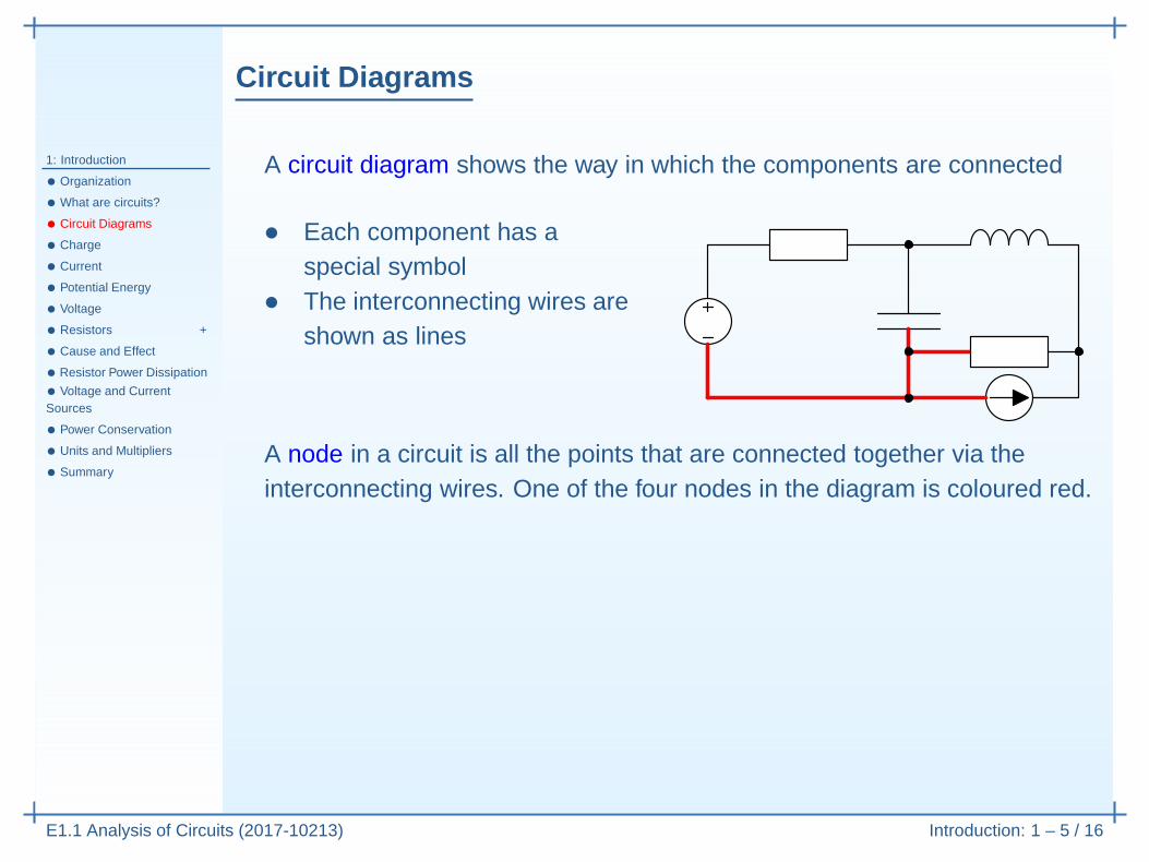
A circuit diagram shows the way in which the components are connected
• Each component has aspecial symbol
• The interconnecting wires areshown as lines
A node in a circuit is all the points that are connected together via theinterconnecting wires. One of the four nodes in the diagram is coloured red.
Circuit Diagrams
1: Introduction
• Organization
• What are circuits?
• Circuit Diagrams
• Charge
• Current
• Potential Energy
• Voltage
• Resistors +
• Cause and Effect
• Resistor Power Dissipation
• Voltage and CurrentSources
• Power Conservation
• Units and Multipliers
• Summary
E1.1 Analysis of Circuits (2017-10213) Introduction: 1 – 5 / 16
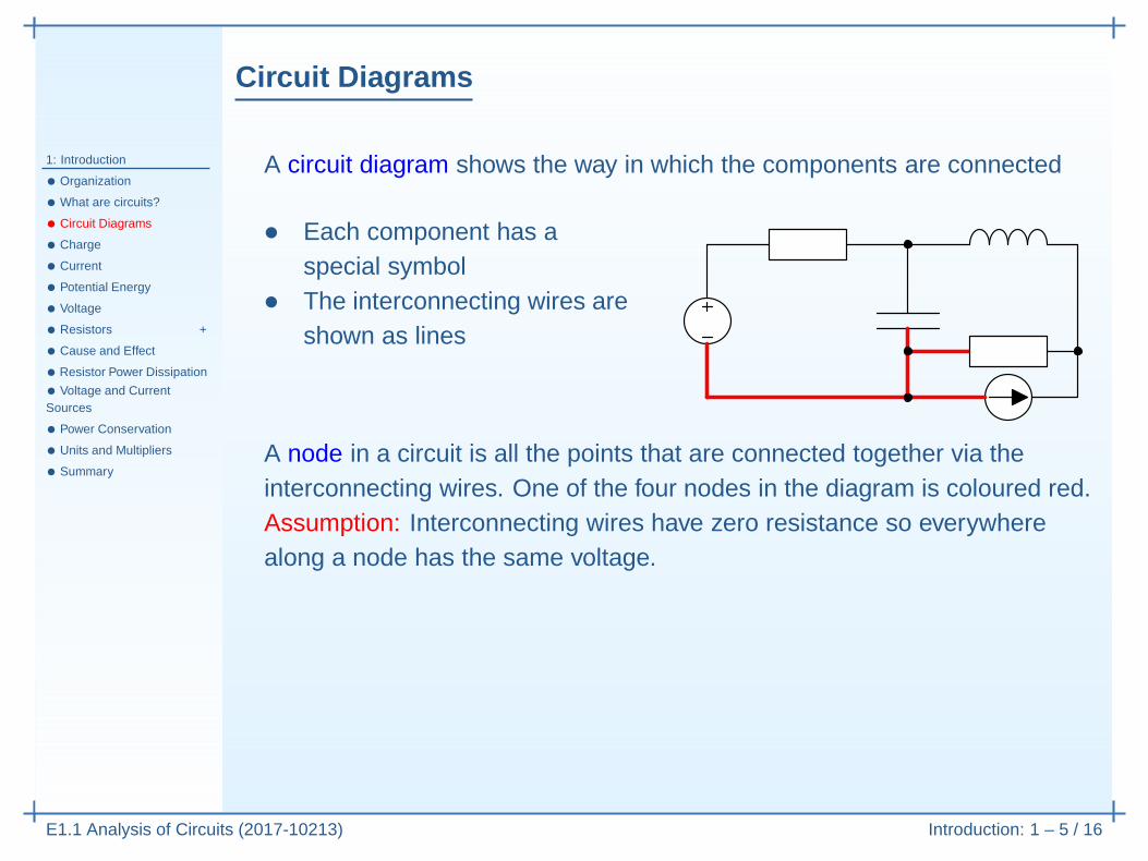
A circuit diagram shows the way in which the components are connected
• Each component has aspecial symbol
• The interconnecting wires areshown as lines
A node in a circuit is all the points that are connected together via theinterconnecting wires. One of the four nodes in the diagram is coloured red.Assumption: Interconnecting wires have zero resistance so everywherealong a node has the same voltage.

Circuit Diagrams
1: Introduction
• Organization
• What are circuits?
• Circuit Diagrams
• Charge
• Current
• Potential Energy
• Voltage
• Resistors +
• Cause and Effect
• Resistor Power Dissipation
• Voltage and CurrentSources
• Power Conservation
• Units and Multipliers
• Summary
E1.1 Analysis of Circuits (2017-10213) Introduction: 1 – 5 / 16
A circuit diagram shows the way in which the components are connected
• Each component has aspecial symbol
• The interconnecting wires areshown as lines
A node in a circuit is all the points that are connected together via theinterconnecting wires. One of the four nodes in the diagram is coloured red.Assumption: Interconnecting wires have zero resistance so everywherealong a node has the same voltage.
Junction Crossover Bad Better
Indicate three meeting wireswith a • and crossoverswithout one.
Avoid having four meeting wires in case the • disappears; stagger the wiresinstead.

Charge
1: Introduction
• Organization
• What are circuits?
• Circuit Diagrams
• Charge
• Current
• Potential Energy
• Voltage
• Resistors +
• Cause and Effect
• Resistor Power Dissipation
• Voltage and CurrentSources
• Power Conservation
• Units and Multipliers
• Summary
E1.1 Analysis of Circuits (2017-10213) Introduction: 1 – 6 / 16
Charge is an electrical property possessed by some atomic particles
Charge
1: Introduction
• Organization
• What are circuits?
• Circuit Diagrams
• Charge
• Current
• Potential Energy
• Voltage
• Resistors +
• Cause and Effect
• Resistor Power Dissipation
• Voltage and CurrentSources
• Power Conservation
• Units and Multipliers
• Summary
E1.1 Analysis of Circuits (2017-10213) Introduction: 1 – 6 / 16
Charge is an electrical property possessed by some atomic particlesCharge is measured in Colombs (abbreviated C)An electron has a charge −1.6× 10⁻¹⁹C, a proton +1.6× 10⁻¹⁹C

Charge
1: Introduction
• Organization
• What are circuits?
• Circuit Diagrams
• Charge
• Current
• Potential Energy
• Voltage
• Resistors +
• Cause and Effect
• Resistor Power Dissipation
• Voltage and CurrentSources
• Power Conservation
• Units and Multipliers
• Summary
E1.1 Analysis of Circuits (2017-10213) Introduction: 1 – 6 / 16
Charge is an electrical property possessed by some atomic particlesCharge is measured in Colombs (abbreviated C)An electron has a charge −1.6× 10⁻¹⁹C, a proton +1.6× 10⁻¹⁹CUnlike charges attract, like charges repel

Charge
1: Introduction
• Organization
• What are circuits?
• Circuit Diagrams
• Charge
• Current
• Potential Energy
• Voltage
• Resistors +
• Cause and Effect
• Resistor Power Dissipation
• Voltage and CurrentSources
• Power Conservation
• Units and Multipliers
• Summary
E1.1 Analysis of Circuits (2017-10213) Introduction: 1 – 6 / 16
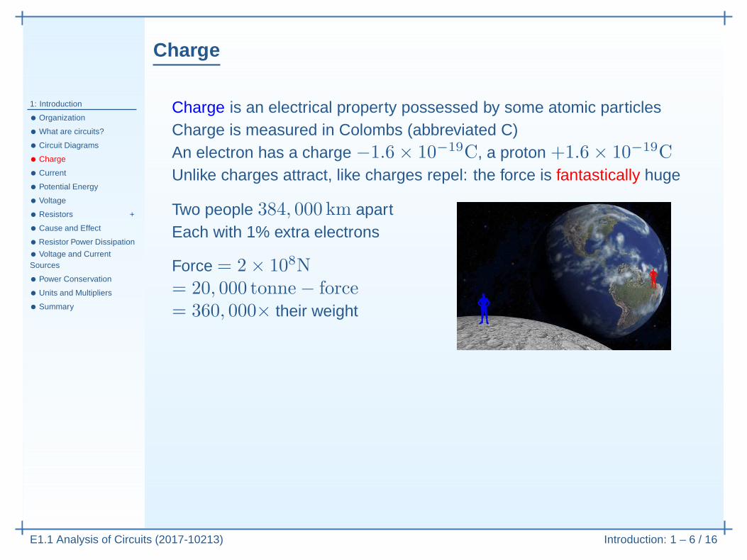
Charge is an electrical property possessed by some atomic particlesCharge is measured in Colombs (abbreviated C)An electron has a charge −1.6× 10⁻¹⁹C, a proton +1.6× 10⁻¹⁹CUnlike charges attract, like charges repel: the force is fantastically huge

Charge
1: Introduction
• Organization
• What are circuits?
• Circuit Diagrams
• Charge
• Current
• Potential Energy
• Voltage
• Resistors +
• Cause and Effect
• Resistor Power Dissipation
• Voltage and CurrentSources
• Power Conservation
• Units and Multipliers
• Summary
E1.1 Analysis of Circuits (2017-10213) Introduction: 1 – 6 / 16
Charge is an electrical property possessed by some atomic particlesCharge is measured in Colombs (abbreviated C)An electron has a charge −1.6× 10⁻¹⁹C, a proton +1.6× 10⁻¹⁹CUnlike charges attract, like charges repel: the force is fantastically huge
Two people 384, 000 km apartEach with 1% extra electrons
Force = 2× 10⁸N= 20, 000 tonne− force= 360, 000× their weight
Consequence: Charge never accumulates in a conductor: everywhere in aconducting path stays electrically neutral at all times.
Current
1: Introduction
• Organization
• What are circuits?
• Circuit Diagrams
• Charge
• Current
• Potential Energy
• Voltage
• Resistors +
• Cause and Effect
• Resistor Power Dissipation
• Voltage and CurrentSources
• Power Conservation
• Units and Multipliers
• Summary
E1.1 Analysis of Circuits (2017-10213) Introduction: 1 – 7 / 16
Current is the flow of charged particles past a measurement boundary

Current
1: Introduction
• Organization
• What are circuits?
• Circuit Diagrams
• Charge
• Current
• Potential Energy
• Voltage
• Resistors +
• Cause and Effect
• Resistor Power Dissipation
• Voltage and CurrentSources
• Power Conservation
• Units and Multipliers
• Summary
E1.1 Analysis of Circuits (2017-10213) Introduction: 1 – 7 / 16
Current is the flow of charged particles past a measurement boundaryUsing an ammeter, we measure current in Ampères (usually abbreviated toAmps or A): 1 A = 1 C/sAnalogy: the flow of water in a pipe or river is measured in litres per second
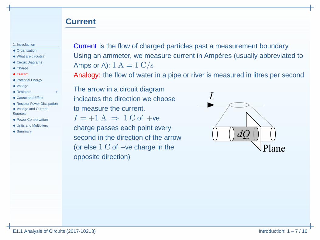
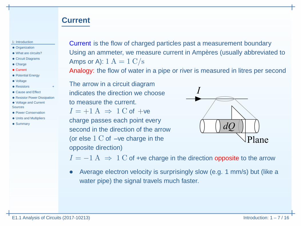
The arrow in a circuit diagramindicates the direction we chooseto measure the current.I = +1 A ⇒ 1 C of +vecharge passes each point everysecond in the direction of the arrow(or else 1 C of –ve charge in theopposite direction)

Current
1: Introduction
• Organization
• What are circuits?
• Circuit Diagrams
• Charge
• Current
• Potential Energy
• Voltage
• Resistors +
• Cause and Effect
• Resistor Power Dissipation
• Voltage and CurrentSources
• Power Conservation
• Units and Multipliers
• Summary
E1.1 Analysis of Circuits (2017-10213) Introduction: 1 – 7 / 16
Current is the flow of charged particles past a measurement boundaryUsing an ammeter, we measure current in Ampères (usually abbreviated toAmps or A): 1 A = 1 C/sAnalogy: the flow of water in a pipe or river is measured in litres per second
The arrow in a circuit diagramindicates the direction we chooseto measure the current.I = +1 A ⇒ 1 C of +vecharge passes each point everysecond in the direction of the arrow(or else 1 C of –ve charge in theopposite direction)
I = −1 A ⇒ 1 C of +ve charge in the direction opposite to the arrow
• Average electron velocity is surprisingly slow (e.g. 1 mm/s) but (like awater pipe) the signal travels much faster.
• In metals the charge carriers (electrons) are actually –ve: in this courseyou should ignore this always.

Potential Energy
1: Introduction
• Organization
• What are circuits?
• Circuit Diagrams
• Charge
• Current
• Potential Energy
• Voltage
• Resistors +
• Cause and Effect
• Resistor Power Dissipation
• Voltage and CurrentSources
• Power Conservation
• Units and Multipliers
• Summary
E1.1 Analysis of Circuits (2017-10213) Introduction: 1 – 8 / 16
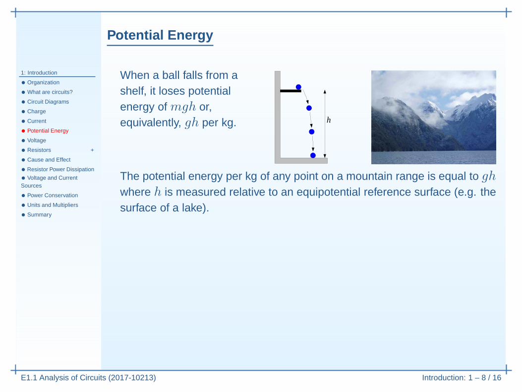
When a ball falls from ashelf, it loses potentialenergy of mgh or,equivalently, gh per kg. h
Potential Energy
1: Introduction
• Organization
• What are circuits?
• Circuit Diagrams
• Charge
• Current
• Potential Energy
• Voltage
• Resistors +
• Cause and Effect
• Resistor Power Dissipation
• Voltage and CurrentSources
• Power Conservation
• Units and Multipliers
• Summary
E1.1 Analysis of Circuits (2017-10213) Introduction: 1 – 8 / 16
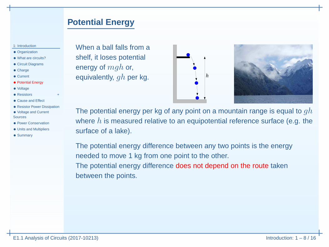
When a ball falls from ashelf, it loses potentialenergy of mgh or,equivalently, gh per kg. h
The potential energy per kg of any point on a mountain range is equal to ghwhere h is measured relative to an equipotential reference surface (e.g. thesurface of a lake).

Potential Energy
1: Introduction
• Organization
• What are circuits?
• Circuit Diagrams
• Charge
• Current
• Potential Energy
• Voltage
• Resistors +
• Cause and Effect
• Resistor Power Dissipation
• Voltage and CurrentSources
• Power Conservation
• Units and Multipliers
• Summary
E1.1 Analysis of Circuits (2017-10213) Introduction: 1 – 8 / 16
When a ball falls from ashelf, it loses potentialenergy of mgh or,equivalently, gh per kg. h
The potential energy per kg of any point on a mountain range is equal to ghwhere h is measured relative to an equipotential reference surface (e.g. thesurface of a lake).
The potential energy difference between any two points is the energyneeded to move 1 kg from one point to the other.
Potential Energy
1: Introduction
• Organization
• What are circuits?
• Circuit Diagrams
• Charge
• Current
• Potential Energy
• Voltage
• Resistors +
• Cause and Effect
• Resistor Power Dissipation
• Voltage and CurrentSources
• Power Conservation
• Units and Multipliers
• Summary
E1.1 Analysis of Circuits (2017-10213) Introduction: 1 – 8 / 16
When a ball falls from ashelf, it loses potentialenergy of mgh or,equivalently, gh per kg. h
The potential energy per kg of any point on a mountain range is equal to ghwhere h is measured relative to an equipotential reference surface (e.g. thesurface of a lake).
The potential energy difference between any two points is the energyneeded to move 1 kg from one point to the other.The potential energy difference does not depend on the route takenbetween the points.

Potential Energy
1: Introduction
• Organization
• What are circuits?
• Circuit Diagrams
• Charge
• Current
• Potential Energy
• Voltage
• Resistors +
• Cause and Effect
• Resistor Power Dissipation
• Voltage and CurrentSources
• Power Conservation
• Units and Multipliers
• Summary
E1.1 Analysis of Circuits (2017-10213) Introduction: 1 – 8 / 16
When a ball falls from ashelf, it loses potentialenergy of mgh or,equivalently, gh per kg. h
The potential energy per kg of any point on a mountain range is equal to ghwhere h is measured relative to an equipotential reference surface (e.g. thesurface of a lake).
The potential energy difference between any two points is the energyneeded to move 1 kg from one point to the other.The potential energy difference does not depend on the route takenbetween the points.The potential enegy difference does not depend on your choice ofreference surface (e.g. lake surface or sea level).

Voltage
1: Introduction
• Organization
• What are circuits?
• Circuit Diagrams
• Charge
• Current
• Potential Energy
• Voltage
• Resistors +
• Cause and Effect
• Resistor Power Dissipation
• Voltage and CurrentSources
• Power Conservation
• Units and Multipliers
• Summary
E1.1 Analysis of Circuits (2017-10213) Introduction: 1 – 9 / 16
The electrical potential difference (or voltage difference) between any twonodes in a circuit is the energy per coulomb needed to move a small +vecharge from one node to the the other.We usually pick one of the nodes as a reference and define the voltage at anode to be the voltage difference between that node and the reference.
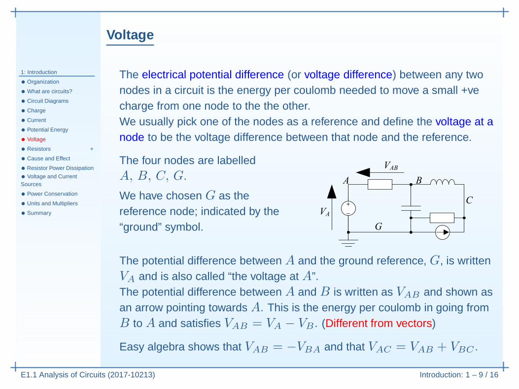
The four nodes are labelledA, B, C, G.
We have chosen G as thereference node; indicated by the“ground” symbol.

Voltage
1: Introduction
• Organization
• What are circuits?
• Circuit Diagrams
• Charge
• Current
• Potential Energy
• Voltage
• Resistors +
• Cause and Effect
• Resistor Power Dissipation
• Voltage and CurrentSources
• Power Conservation
• Units and Multipliers
• Summary
E1.1 Analysis of Circuits (2017-10213) Introduction: 1 – 9 / 16
The electrical potential difference (or voltage difference) between any twonodes in a circuit is the energy per coulomb needed to move a small +vecharge from one node to the the other.We usually pick one of the nodes as a reference and define the voltage at anode to be the voltage difference between that node and the reference.
The four nodes are labelledA, B, C, G.
We have chosen G as thereference node; indicated by the“ground” symbol.
The potential difference between A and the ground reference, G, is writtenVA and is also called “the voltage at A”.

Voltage
1: Introduction
• Organization
• What are circuits?
• Circuit Diagrams
• Charge
• Current
• Potential Energy
• Voltage
• Resistors +
• Cause and Effect
• Resistor Power Dissipation
• Voltage and CurrentSources
• Power Conservation
• Units and Multipliers
• Summary
E1.1 Analysis of Circuits (2017-10213) Introduction: 1 – 9 / 16
The electrical potential difference (or voltage difference) between any twonodes in a circuit is the energy per coulomb needed to move a small +vecharge from one node to the the other.We usually pick one of the nodes as a reference and define the voltage at anode to be the voltage difference between that node and the reference.
The four nodes are labelledA, B, C, G.
We have chosen G as thereference node; indicated by the“ground” symbol.
The potential difference between A and the ground reference, G, is writtenVA and is also called “the voltage at A”.The potential difference between A and B is written as VAB and shown asan arrow pointing towards A. This is the energy per coulomb in going fromB to A and satisfies VAB = VA − VB . (Different from vectors)
Easy algebra shows that VAB = −VBA and that VAC = VAB + VBC .
Resistors +
1: Introduction
• Organization
• What are circuits?
• Circuit Diagrams
• Charge
• Current
• Potential Energy
• Voltage
• Resistors +
• Cause and Effect
• Resistor Power Dissipation
• Voltage and CurrentSources
• Power Conservation
• Units and Multipliers
• Summary
E1.1 Analysis of Circuits (2017-10213) Introduction: 1 – 10 / 16
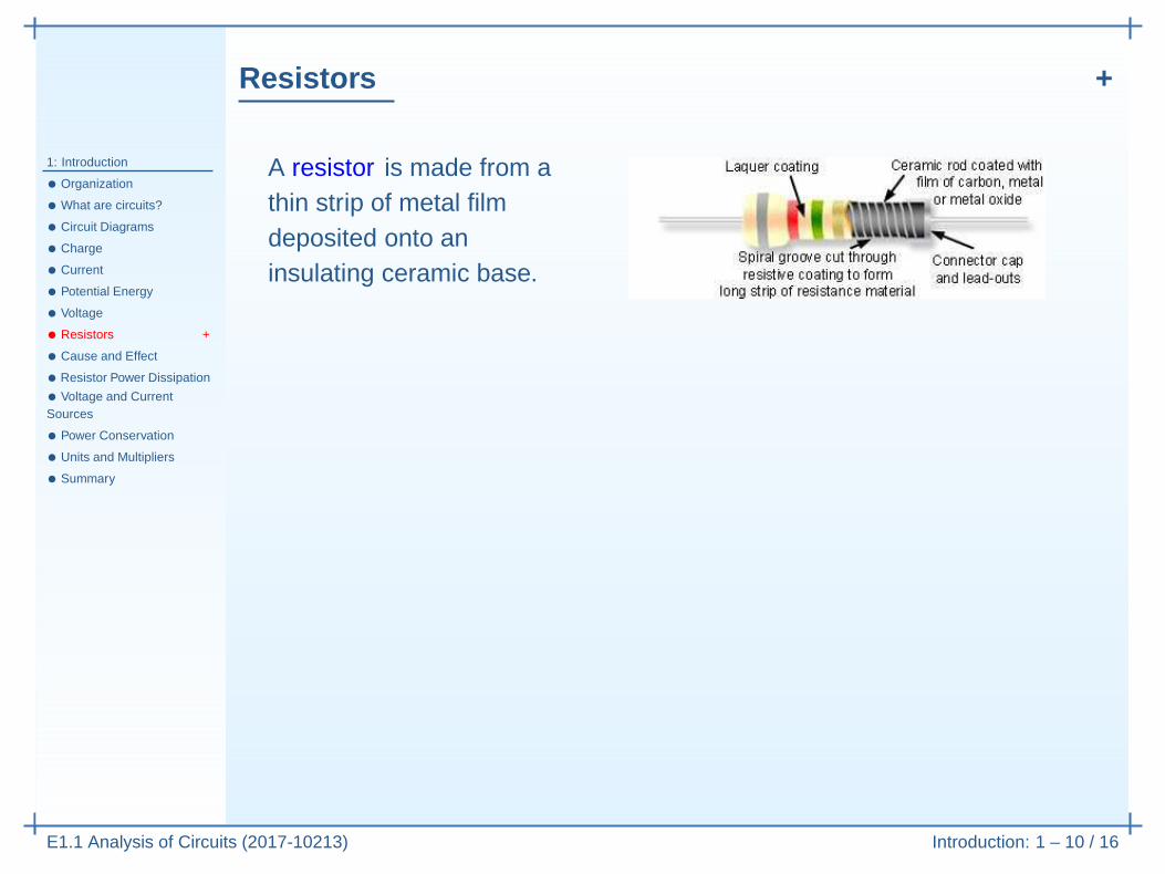
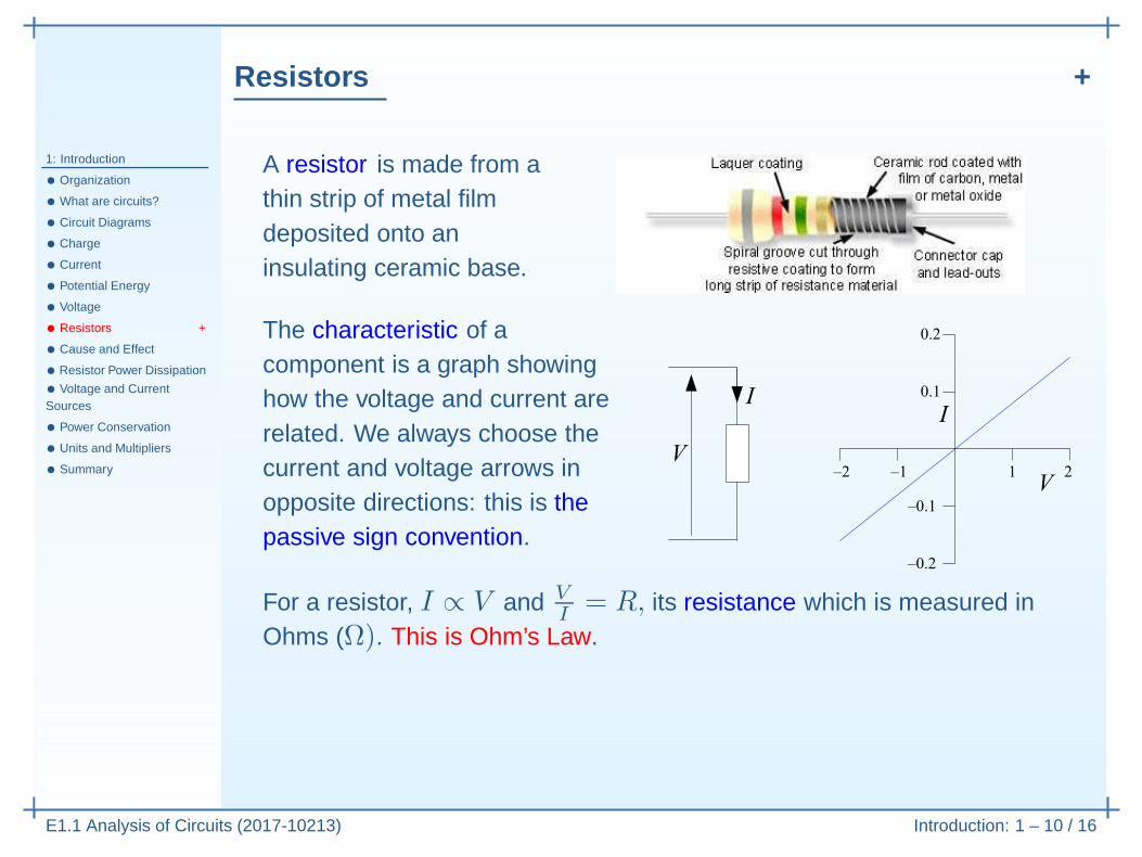
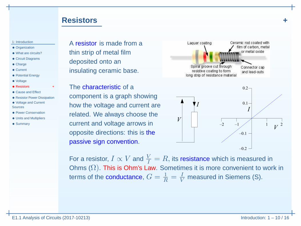
A resistor is made from athin strip of metal filmdeposited onto aninsulating ceramic base.

Resistors +
1: Introduction
• Organization
• What are circuits?
• Circuit Diagrams
• Charge
• Current
• Potential Energy
• Voltage
• Resistors +
• Cause and Effect
• Resistor Power Dissipation
• Voltage and CurrentSources
• Power Conservation
• Units and Multipliers
• Summary
E1.1 Analysis of Circuits (2017-10213) Introduction: 1 – 10 / 16
A resistor is made from athin strip of metal filmdeposited onto aninsulating ceramic base.
The characteristic of acomponent is a graph showinghow the voltage and current arerelated. We always choose thecurrent and voltage arrows inopposite directions: this is thepassive sign convention.
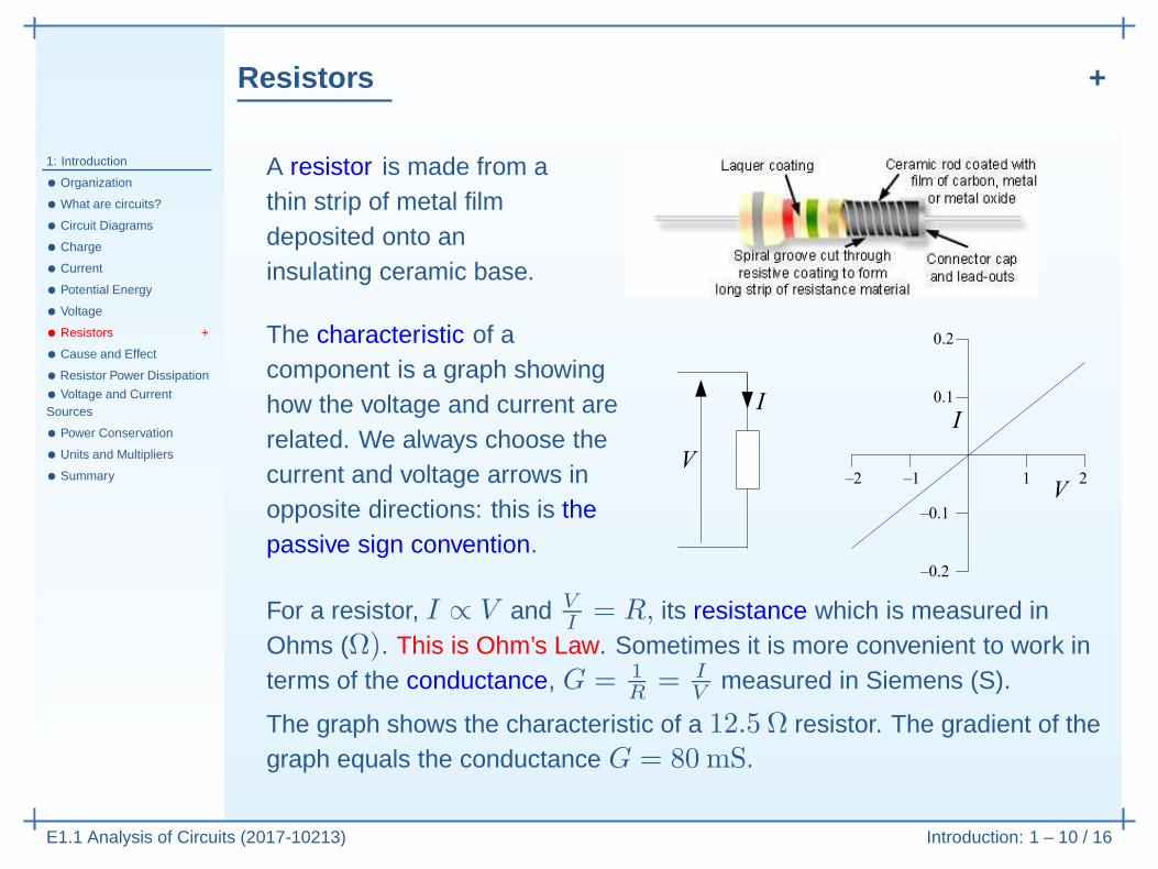
For a resistor, I ∝ V and V
I= R, its resistance which is measured in
Ohms (Ω). This is Ohm’s Law.
Resistors +
1: Introduction
• Organization
• What are circuits?
• Circuit Diagrams
• Charge
• Current
• Potential Energy
• Voltage
• Resistors +
• Cause and Effect
• Resistor Power Dissipation
• Voltage and CurrentSources
• Power Conservation
• Units and Multipliers
• Summary
E1.1 Analysis of Circuits (2017-10213) Introduction: 1 – 10 / 16
A resistor is made from athin strip of metal filmdeposited onto aninsulating ceramic base.
The characteristic of acomponent is a graph showinghow the voltage and current arerelated. We always choose thecurrent and voltage arrows inopposite directions: this is thepassive sign convention.
For a resistor, I ∝ V and V
I= R, its resistance which is measured in
Ohms (Ω). This is Ohm’s Law. Sometimes it is more convenient to work interms of the conductance, G = 1
R= I
Vmeasured in Siemens (S).
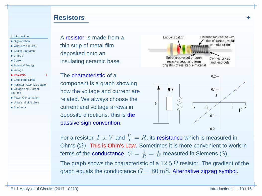
The graph shows the characteristic of a 12.5 Ω resistor. The gradient of thegraph equals the conductance G = 80 mS.
Resistors +
1: Introduction
• Organization
• What are circuits?
• Circuit Diagrams
• Charge
• Current
• Potential Energy
• Voltage
• Resistors +
• Cause and Effect
• Resistor Power Dissipation
• Voltage and CurrentSources
• Power Conservation
• Units and Multipliers
• Summary
E1.1 Analysis of Circuits (2017-10213) Introduction: 1 – 10 / 16
A resistor is made from athin strip of metal filmdeposited onto aninsulating ceramic base.
The characteristic of acomponent is a graph showinghow the voltage and current arerelated. We always choose thecurrent and voltage arrows inopposite directions: this is thepassive sign convention.
For a resistor, I ∝ V and V
I= R, its resistance which is measured in
Ohms (Ω). This is Ohm’s Law. Sometimes it is more convenient to work interms of the conductance, G = 1
R= I
Vmeasured in Siemens (S).
The graph shows the characteristic of a 12.5 Ω resistor. The gradient of thegraph equals the conductance G = 80 mS. Alternative zigzag symbol.
Cause and Effect
1: Introduction
• Organization
• What are circuits?
• Circuit Diagrams
• Charge
• Current
• Potential Energy
• Voltage
• Resistors +
• Cause and Effect
• Resistor Power Dissipation
• Voltage and CurrentSources
• Power Conservation
• Units and Multipliers
• Summary
E1.1 Analysis of Circuits (2017-10213) Introduction: 1 – 11 / 16
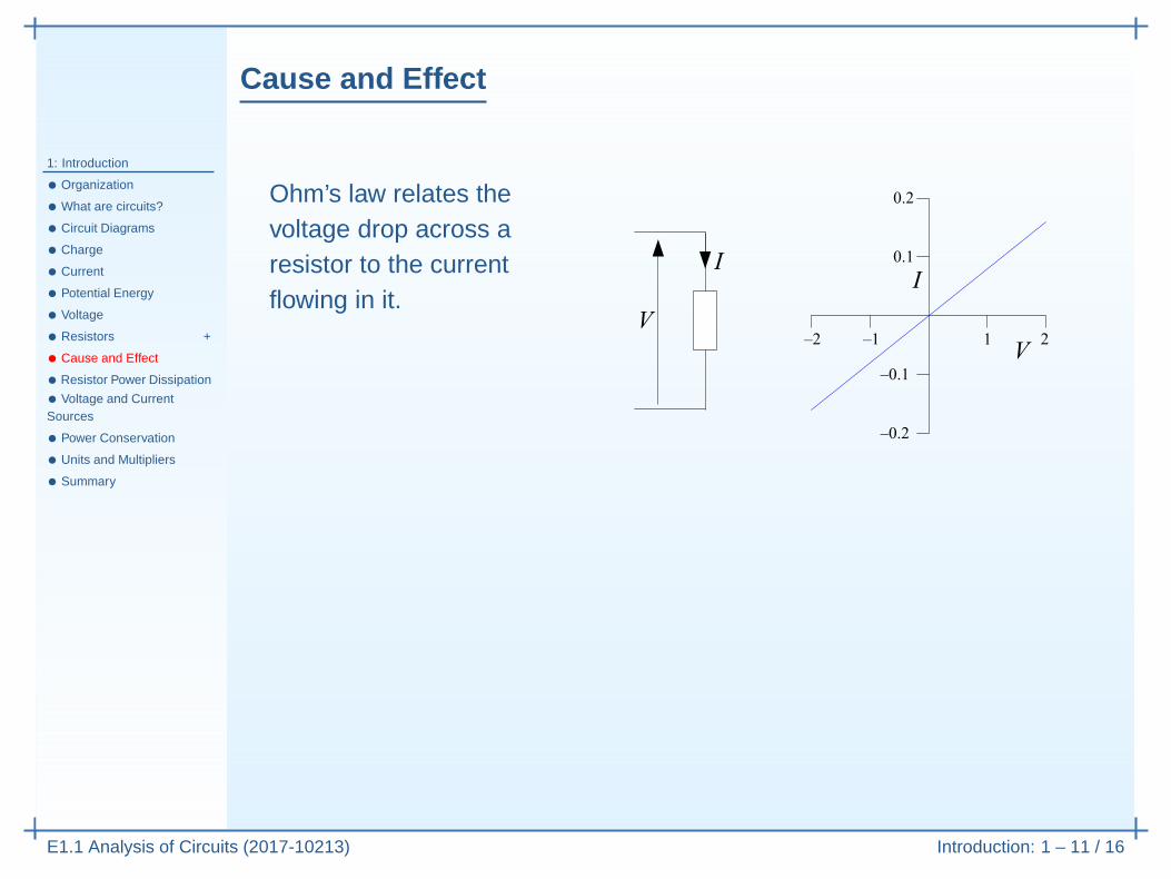
Ohm’s law relates thevoltage drop across aresistor to the currentflowing in it.

Cause and Effect
1: Introduction
• Organization
• What are circuits?
• Circuit Diagrams
• Charge
• Current
• Potential Energy
• Voltage
• Resistors +
• Cause and Effect
• Resistor Power Dissipation
• Voltage and CurrentSources
• Power Conservation
• Units and Multipliers
• Summary
E1.1 Analysis of Circuits (2017-10213) Introduction: 1 – 11 / 16
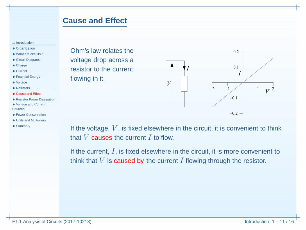
Ohm’s law relates thevoltage drop across aresistor to the currentflowing in it.
If the voltage, V , is fixed elsewhere in the circuit, it is convenient to thinkthat V causes the current I to flow.
Cause and Effect
1: Introduction
• Organization
• What are circuits?
• Circuit Diagrams
• Charge
• Current
• Potential Energy
• Voltage
• Resistors +
• Cause and Effect
• Resistor Power Dissipation
• Voltage and CurrentSources
• Power Conservation
• Units and Multipliers
• Summary
E1.1 Analysis of Circuits (2017-10213) Introduction: 1 – 11 / 16
Ohm’s law relates thevoltage drop across aresistor to the currentflowing in it.
If the voltage, V , is fixed elsewhere in the circuit, it is convenient to thinkthat V causes the current I to flow.
If the current, I , is fixed elsewhere in the circuit, it is more convenient tothink that V is caused by the current I flowing through the resistor.
Cause and Effect
1: Introduction
• Organization
• What are circuits?
• Circuit Diagrams
• Charge
• Current
• Potential Energy
• Voltage
• Resistors +
• Cause and Effect
• Resistor Power Dissipation
• Voltage and CurrentSources
• Power Conservation
• Units and Multipliers
• Summary
E1.1 Analysis of Circuits (2017-10213) Introduction: 1 – 11 / 16
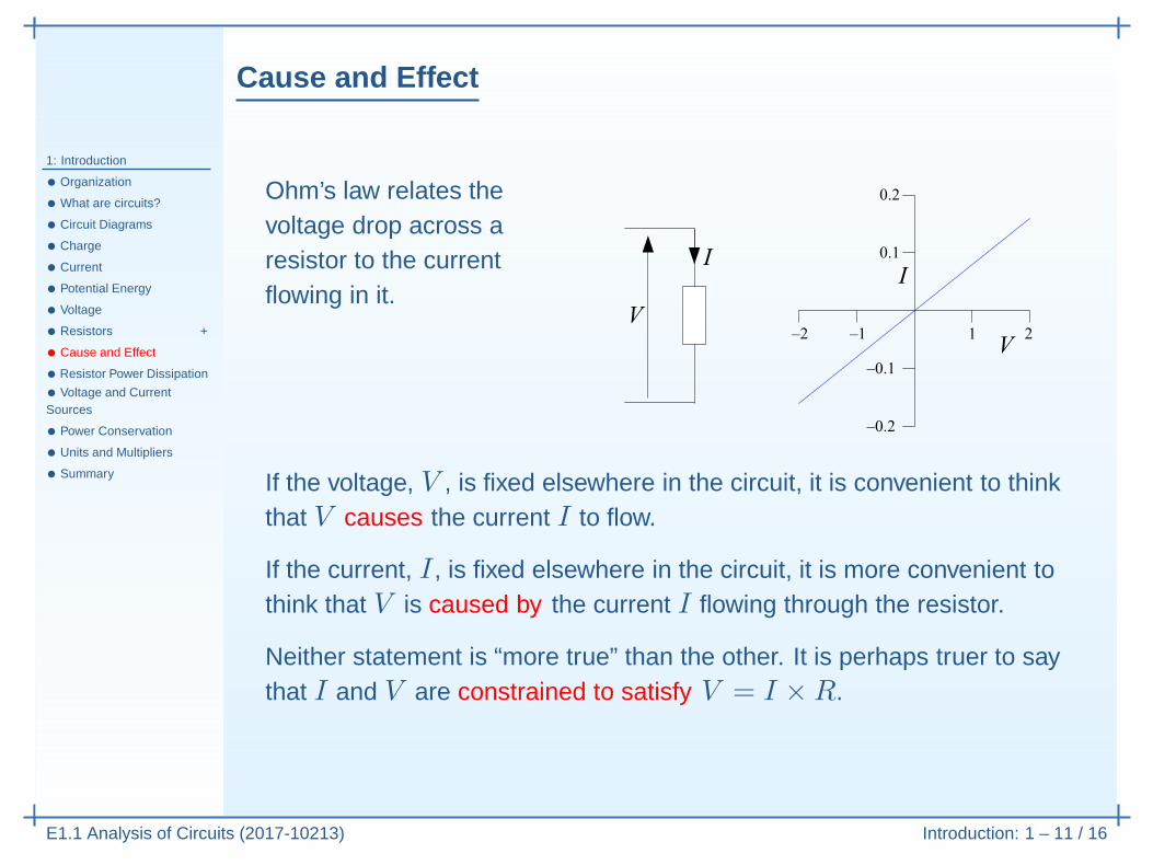
Ohm’s law relates thevoltage drop across aresistor to the currentflowing in it.
If the voltage, V , is fixed elsewhere in the circuit, it is convenient to thinkthat V causes the current I to flow.
If the current, I , is fixed elsewhere in the circuit, it is more convenient tothink that V is caused by the current I flowing through the resistor.
Neither statement is “more true” than the other. It is perhaps truer to saythat I and V are constrained to satisfy V = I ×R.
Resistor Power Dissipation
1: Introduction
• Organization
• What are circuits?
• Circuit Diagrams
• Charge
• Current
• Potential Energy
• Voltage
• Resistors +
• Cause and Effect
• Resistor Power Dissipation
• Voltage and CurrentSources
• Power Conservation
• Units and Multipliers
• Summary
E1.1 Analysis of Circuits (2017-10213) Introduction: 1 – 12 / 16
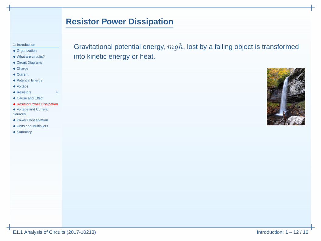
Gravitational potential energy, mgh, lost by a falling object is transformedinto kinetic energy or heat.

Resistor Power Dissipation
1: Introduction
• Organization
• What are circuits?
• Circuit Diagrams
• Charge
• Current
• Potential Energy
• Voltage
• Resistors +
• Cause and Effect
• Resistor Power Dissipation
• Voltage and CurrentSources
• Power Conservation
• Units and Multipliers
• Summary
E1.1 Analysis of Circuits (2017-10213) Introduction: 1 – 12 / 16
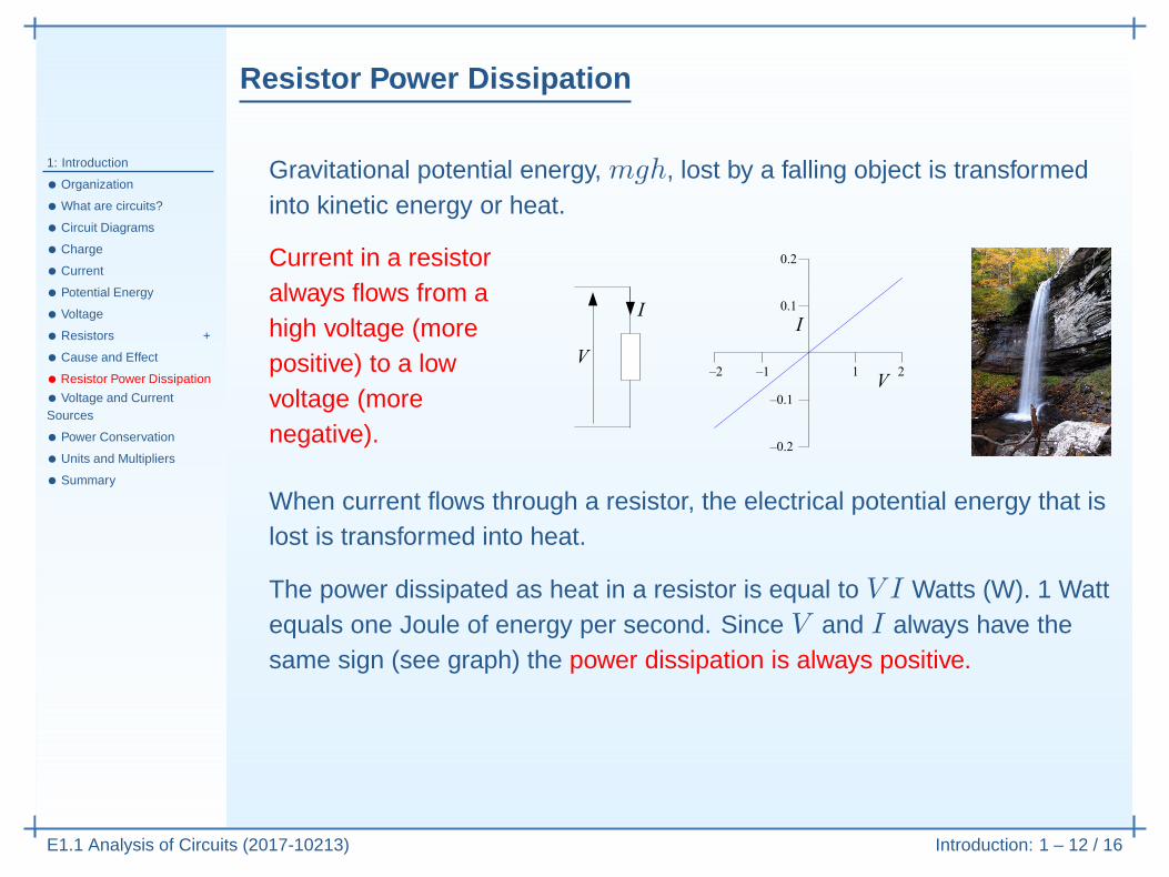
Gravitational potential energy, mgh, lost by a falling object is transformedinto kinetic energy or heat.
Current in a resistoralways flows from ahigh voltage (morepositive) to a lowvoltage (morenegative).
When current flows through a resistor, the electrical potential energy that islost is transformed into heat.
Resistor Power Dissipation
1: Introduction
• Organization
• What are circuits?
• Circuit Diagrams
• Charge
• Current
• Potential Energy
• Voltage
• Resistors +
• Cause and Effect
• Resistor Power Dissipation
• Voltage and CurrentSources
• Power Conservation
• Units and Multipliers
• Summary
E1.1 Analysis of Circuits (2017-10213) Introduction: 1 – 12 / 16
Gravitational potential energy, mgh, lost by a falling object is transformedinto kinetic energy or heat.
Current in a resistoralways flows from ahigh voltage (morepositive) to a lowvoltage (morenegative).
When current flows through a resistor, the electrical potential energy that islost is transformed into heat.
The power dissipated as heat in a resistor is equal to V I Watts (W). 1 Wattequals one Joule of energy per second. Since V and I always have thesame sign (see graph) the power dissipation is always positive.
Any component: P = V I gives the power absorbed by any component.
For a resistor only: V
I= R ⇒ P = V I = V
2
R= I2R.

Voltage and Current Sources
1: Introduction
• Organization
• What are circuits?
• Circuit Diagrams
• Charge
• Current
• Potential Energy
• Voltage
• Resistors +
• Cause and Effect
• Resistor Power Dissipation
• Voltage and CurrentSources
• Power Conservation
• Units and Multipliers
• Summary
E1.1 Analysis of Circuits (2017-10213) Introduction: 1 – 13 / 16
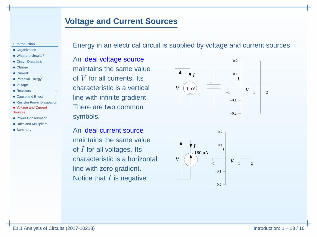
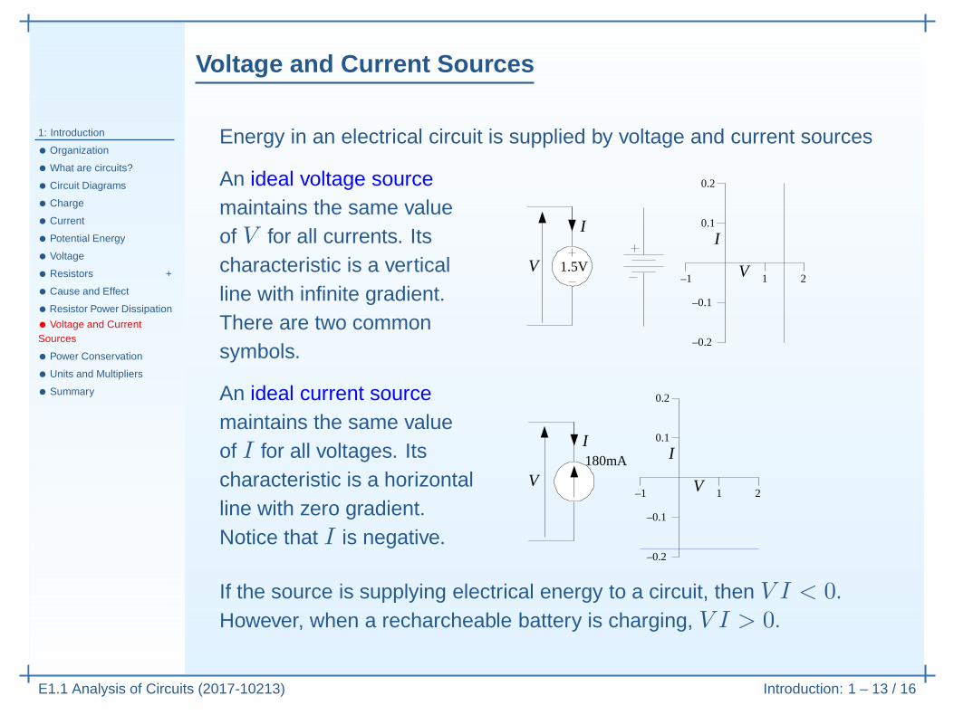
Energy in an electrical circuit is supplied by voltage and current sources
An ideal voltage sourcemaintains the same valueof V for all currents. Itscharacteristic is a verticalline with infinite gradient.There are two commonsymbols.
V
I
1–1 2
0.1
0.2
–0.1
–0.2
I
V 1.5V
Voltage and Current Sources
1: Introduction
• Organization
• What are circuits?
• Circuit Diagrams
• Charge
• Current
• Potential Energy
• Voltage
• Resistors +
• Cause and Effect
• Resistor Power Dissipation
• Voltage and CurrentSources
• Power Conservation
• Units and Multipliers
• Summary
E1.1 Analysis of Circuits (2017-10213) Introduction: 1 – 13 / 16
Energy in an electrical circuit is supplied by voltage and current sources
An ideal voltage sourcemaintains the same valueof V for all currents. Itscharacteristic is a verticalline with infinite gradient.There are two commonsymbols.
V
I
1–1 2
0.1
0.2
–0.1
–0.2
I
V 1.5V
An ideal current sourcemaintains the same valueof I for all voltages. Itscharacteristic is a horizontalline with zero gradient.Notice that I is negative.
V
I
1–1 2
0.1
0.2
–0.1
–0.2
I
V180mA
If the source is supplying electrical energy to a circuit, then V I < 0.However, when a recharcheable battery is charging, V I > 0.
Power Conservation
1: Introduction
• Organization
• What are circuits?
• Circuit Diagrams
• Charge
• Current
• Potential Energy
• Voltage
• Resistors +
• Cause and Effect
• Resistor Power Dissipation
• Voltage and CurrentSources
• Power Conservation
• Units and Multipliers
• Summary
E1.1 Analysis of Circuits (2017-10213) Introduction: 1 – 14 / 16
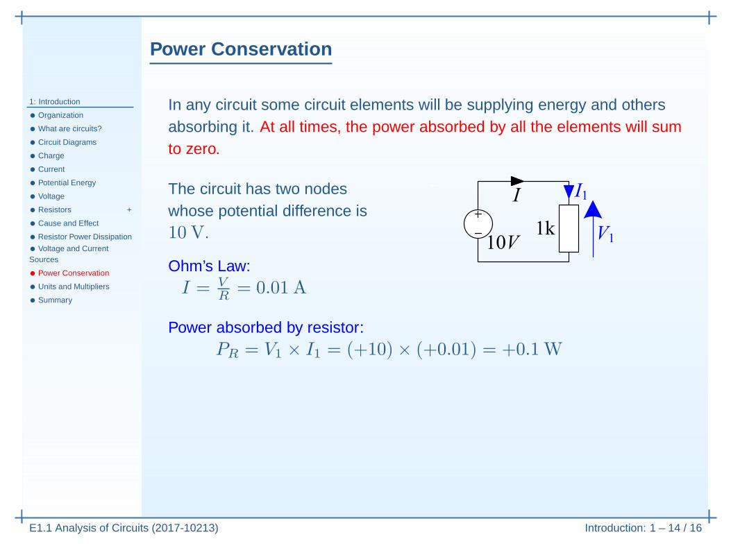
In any circuit some circuit elements will be supplying energy and othersabsorbing it. At all times, the power absorbed by all the elements will sumto zero.

Power Conservation
1: Introduction
• Organization
• What are circuits?
• Circuit Diagrams
• Charge
• Current
• Potential Energy
• Voltage
• Resistors +
• Cause and Effect
• Resistor Power Dissipation
• Voltage and CurrentSources
• Power Conservation
• Units and Multipliers
• Summary
E1.1 Analysis of Circuits (2017-10213) Introduction: 1 – 14 / 16
In any circuit some circuit elements will be supplying energy and othersabsorbing it. At all times, the power absorbed by all the elements will sumto zero.
The circuit has two nodeswhose potential difference is10 V.
Ohm’s Law:I = V
R= 0.01 A
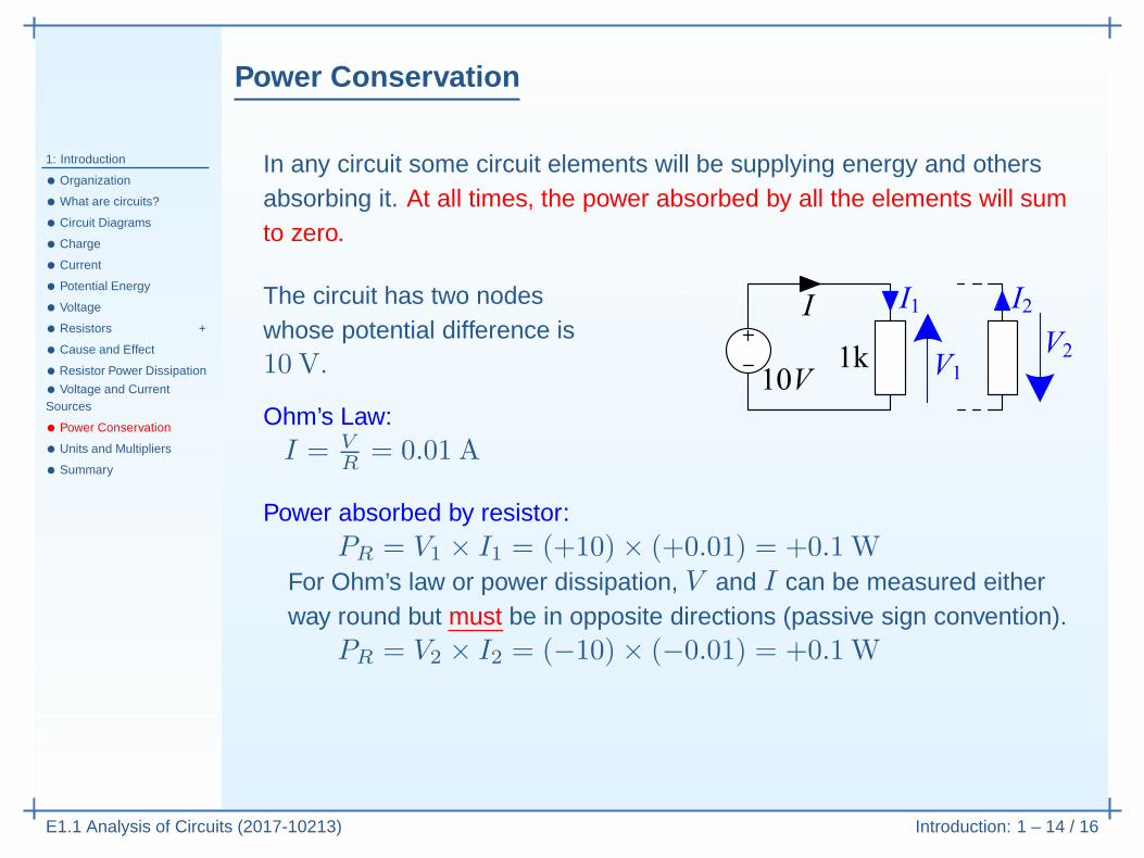
Power absorbed by resistor:PR = V1 × I1 = (+10)× (+0.01) = +0.1W

Power Conservation
1: Introduction
• Organization
• What are circuits?
• Circuit Diagrams
• Charge
• Current
• Potential Energy
• Voltage
• Resistors +
• Cause and Effect
• Resistor Power Dissipation
• Voltage and CurrentSources
• Power Conservation
• Units and Multipliers
• Summary
E1.1 Analysis of Circuits (2017-10213) Introduction: 1 – 14 / 16
In any circuit some circuit elements will be supplying energy and othersabsorbing it. At all times, the power absorbed by all the elements will sumto zero.
The circuit has two nodeswhose potential difference is10 V.
Ohm’s Law:I = V
R= 0.01 A
Power absorbed by resistor:PR = V1 × I1 = (+10)× (+0.01) = +0.1W
For Ohm’s law or power dissipation, V and I can be measured eitherway round but must be in opposite directions (passive sign convention).
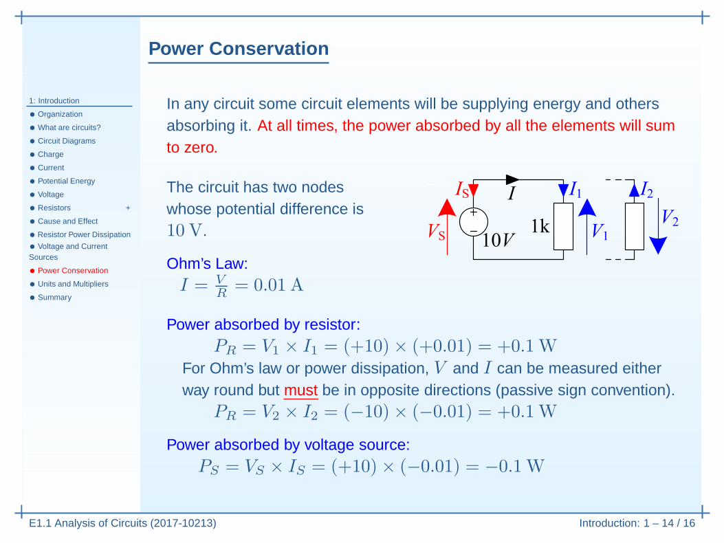
PR = V2 × I2 = (−10)× (−0.01) = +0.1W
Power Conservation
1: Introduction
• Organization
• What are circuits?
• Circuit Diagrams
• Charge
• Current
• Potential Energy
• Voltage
• Resistors +
• Cause and Effect
• Resistor Power Dissipation
• Voltage and CurrentSources
• Power Conservation
• Units and Multipliers
• Summary
E1.1 Analysis of Circuits (2017-10213) Introduction: 1 – 14 / 16
In any circuit some circuit elements will be supplying energy and othersabsorbing it. At all times, the power absorbed by all the elements will sumto zero.
The circuit has two nodeswhose potential difference is10 V.
Ohm’s Law:I = V
R= 0.01 A
Power absorbed by resistor:PR = V1 × I1 = (+10)× (+0.01) = +0.1W
For Ohm’s law or power dissipation, V and I can be measured eitherway round but must be in opposite directions (passive sign convention).
PR = V2 × I2 = (−10)× (−0.01) = +0.1W
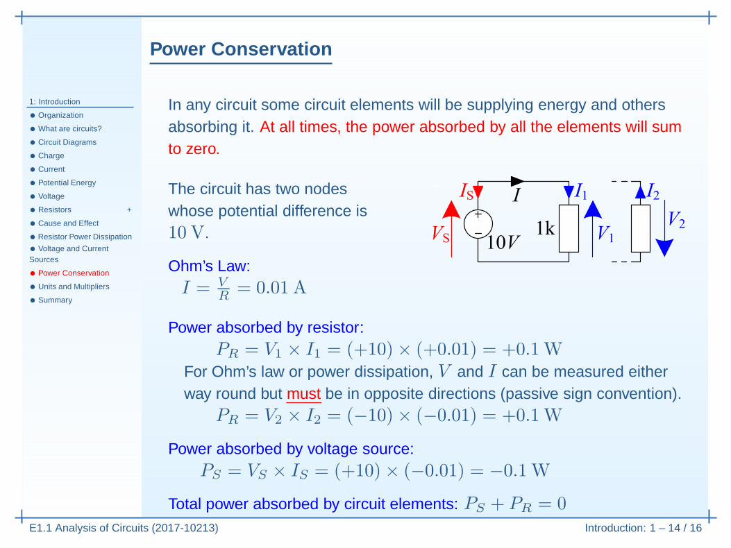
Power absorbed by voltage source:PS = VS × IS = (+10)× (−0.01) = −0.1W
Power Conservation
1: Introduction
• Organization
• What are circuits?
• Circuit Diagrams
• Charge
• Current
• Potential Energy
• Voltage
• Resistors +
• Cause and Effect
• Resistor Power Dissipation
• Voltage and CurrentSources
• Power Conservation
• Units and Multipliers
• Summary
E1.1 Analysis of Circuits (2017-10213) Introduction: 1 – 14 / 16
In any circuit some circuit elements will be supplying energy and othersabsorbing it. At all times, the power absorbed by all the elements will sumto zero.
The circuit has two nodeswhose potential difference is10 V.
Ohm’s Law:I = V
R= 0.01 A
Power absorbed by resistor:PR = V1 × I1 = (+10)× (+0.01) = +0.1W
For Ohm’s law or power dissipation, V and I can be measured eitherway round but must be in opposite directions (passive sign convention).
PR = V2 × I2 = (−10)× (−0.01) = +0.1W
Power absorbed by voltage source:PS = VS × IS = (+10)× (−0.01) = −0.1W
Total power absorbed by circuit elements: PS + PR = 0

Units and Multipliers
1: Introduction
• Organization
• What are circuits?
• Circuit Diagrams
• Charge
• Current
• Potential Energy
• Voltage
• Resistors +
• Cause and Effect
• Resistor Power Dissipation
• Voltage and CurrentSources
• Power Conservation
• Units and Multipliers
• Summary
E1.1 Analysis of Circuits (2017-10213) Introduction: 1 – 15 / 16
Quantity Letter Unit Symbol
Charge Q Coulomb CConductance G Siemens S
Current I Amp AEnergy W Joule J
Potential V Volt VPower P Watt W
Resistance R Ohm Ω
Value Prefix Symbol
10−3 milli m10−6 micro µ10−9 nano n10−12 pico p10−15 femto f
Value Prefix Symbol
103 kilo k106 mega M109 giga G1012 tera T1015 peta P

Summary
1: Introduction
• Organization
• What are circuits?
• Circuit Diagrams
• Charge
• Current
• Potential Energy
• Voltage
• Resistors +
• Cause and Effect
• Resistor Power Dissipation
• Voltage and CurrentSources
• Power Conservation
• Units and Multipliers
• Summary
E1.1 Analysis of Circuits (2017-10213) Introduction: 1 – 16 / 16
• Circuits and Nodes
• Charge, Current and Voltage
• Resistors, Voltage Source and Current Sources
• Power Dissipation and Power Conservation
For further details see Hayt Ch 2 or Irwin Ch 1.