E1 SUMMARY
37
ACCESSORIES E1 E1.3 SUMMARY INTRODUCTION LINE ON LINE ® E1.4 IN-LINE PNEUMATIC VALVE SERIES PNV L E1.6 IN-LINE SOLENOID VALVE SERIES SOV L E1.9 MINIATURE REDUCER/ECONOMIZER, SERIES RML, RMC AND RMS E1.12 IN-LINE PRESSURE GAUGE SERIES MAN L E1.16 IN-LINE PRESSURE INDICATOR SERIES LAM L E1.18 IN-LINE SHUTOFF VALVE SERIES V2V L AND V3V L E1.20 IN-LINE FLOW MICRO-REGULATOR SERIES RFL L E1.23 IN-LINE FIXED-REGULATION FLOW REGULATOR SERIE RFF L E1.26 IN-LINE QUICK-EXHAUST VALVES SERIES VSR L E1.29 IN-LINE QUICK-EXHAUST VALVE WITH REGULATED EXHAUST SERIES VSRR L E1.31 IN-LINE STOP VALVE SERIES STP L E1.34 IN-LINE CHECK VALVE SERIES VNR L E1.37 LINE ON LINE ® ACCESSORIES E1.39 SUMMARY LINE ON LINE ®
Transcript of E1 SUMMARY

ACC
ESSO
RIES
E1
E1.3
SUMMARY
� INTRODUCTION LINE ON LINE® E1.4
� IN-LINE PNEUMATIC VALVE SERIES PNV L E1.6
� IN-LINE SOLENOID VALVE SERIES SOV L E1.9
� MINIATURE REDUCER/ECONOMIZER, SERIES RML, RMC AND RMS E1.12
� IN-LINE PRESSURE GAUGE SERIES MAN L E1.16
� IN-LINE PRESSURE INDICATOR SERIES LAM L E1.18
� IN-LINE SHUTOFF VALVE SERIES V2V L AND V3V L E1.20
� IN-LINE FLOW MICRO-REGULATOR SERIES RFL L E1.23
� IN-LINE FIXED-REGULATION FLOW REGULATOR SERIE RFF L E1.26
� IN-LINE QUICK-EXHAUST VALVES SERIES VSR L E1.29
� IN-LINE QUICK-EXHAUST VALVE WITH REGULATED EXHAUST SERIES VSRR L E1.31
� IN-LINE STOP VALVE SERIES STP L E1.34
� IN-LINE CHECK VALVE SERIES VNR L E1.37
� LINE ON LINE® ACCESSORIES E1.39
SUM
MA
RY L
INE
ON
LIN
E®

ACC
ESSO
RIES
E1
E1.4
CONNECTION FREE
FIXING FREE
LINE OF PRODUCTS ON LINE
INTR
OD
UC
TIO
N L
INE
ON
LIN
E®
LINE ON LINE® is an exclusive range of products for mounting on pneu-matic circuits. With these small, highly efficient components it is possible to perform all pneumatic functions at any point of the circuit. LINE ON LINE® is ultra-modular - the components can be connected in parallel, in series or combined parallel/series. All LINE ON LINE® products are available for pipe-pipe connection with two push-in fittings, or for thread-pipe connection with a brass nickel-plated male thread and a push-in fitting.The body is made of technopolymer, giving a product that is extremely lightweight and compact. One side of the body is marked with an indelible pneumatic symbol to facilitate identification and indicate the direction of flow.
PARALLEL LINES SERIAL LINE PARALLEL FITTING SERIAL LINE IN-LINE FITTING
WALL FIXING PLATE FIXING PANEL FIXING UNDER WALL FIXING
#TAG_E1_00010

ACC
ESSO
RIES
E1
E1.5
ALL THE PNEUMATIC FUNCTIONS WITH THE SAME EXTERNAL DIMENSIONS
PIPE-PIPE
APPLICATION EXAMPLE
THREAD-PIPE
INTR
OD
UC
TIO
N L
INE
ON
LIN
E®

ACC
ESSO
RIES
E1
E1.6
The PNV L in-line pneumatic valve belongs to the LINE ON LINE® family and can be connected in series or in parallel with the other products in the same family.It is available in a version for pipe-pipe connection, which includes two push-in fittings, and a version for thread-pipe connection, which includes a nickel-plated brass male thread and a push-in fitting. The compressed air port is a push-in fitting for Ø 4 pipe. The valve is the normally-closed 3/2 pipe. It is a unidirectional valve, meaning it only works properly if supplied from port 1.
TECHNICAL DATA
COMPONENTS
Max. operating pressure MPa bar psiTemperature range °C °FRecommended pipeFluidCompatibility with oils
Ø 6 Ø 8
110145
– 20 to + 60– 4 to + 140
Rilsan PA 11 - Nylon 6 - Polyamide 12 - PolypropyleneLubricated or unlubricated filtered air
See chapter Z1
� Technopolymer body� Nickel-plated brass insert� Nickel-plated brass pilot insert� Brass piston rod� Stainless steel clamping spring� NBR seal� Stainless steel poppet spring NBR seal Technopolymer spring ring� Stainless steel clamping spring� Technopolymer stop bushing Technopolymer release bushing
IN-LINE PNEUMATIC VALVE SERIES PNV L
IN-L
INE
PNEU
MA
TIC
VA
LVE
SERI
ES P
NV
L
#TAG_E1_00020
ACC
ESSO
RIES
E1
E1.7
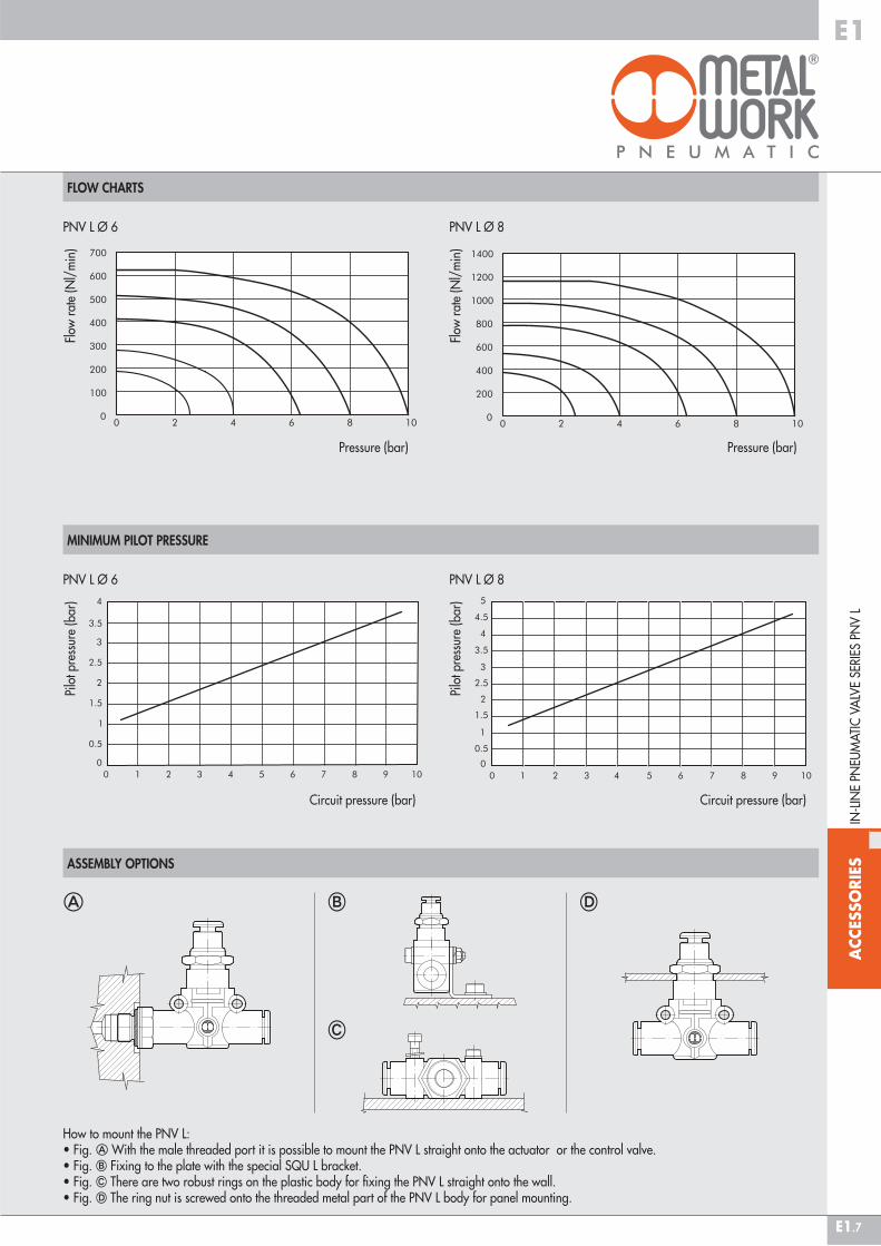
FLOW CHARTS
ASSEMBLY OPTIONSIN
-LIN
E PN
EUM
ATI
C V
ALV
E SE
RIES
PN
V L
� � �
How to mount the PNV L:• Fig. � With the male threaded port it is possible to mount the PNV L straight onto the actuator or the control valve.• Fig. � Fixing to the plate with the special SQU L bracket.• Fig. � There are two robust rings on the plastic body for fixing the PNV L straight onto the wall.• Fig. � The ring nut is screwed onto the threaded metal part of the PNV L body for panel mounting.
�
MINIMUM PILOT PRESSURE
PNV L Ø 6
Circuit pressure (bar)
PNV L Ø 8
Circuit pressure (bar)
Pilo
t pre
ssur
e (b
ar)
Pilo
t pre
ssur
e (b
ar)
PNV L Ø 6
Pressure (bar)
PNV L Ø 8
Pressure (bar)
Flow
rat
e (N
l/m
in)
Flow
rat
e (N
l/m
in)

ACC
ESSO
RIES
E1
E1.8
PNV L 3/2 NC PIPE - PIPE
PNV L 3/2 NC PIPE - THREAD
PNV L 3/2 NC THREAD - PIPE
Code Ref. F Ø P A A1 B C D E E1 G H I I1 Ch Nmax9067808 PNV L 3/2 NC Ø6 - 1/8 1/8 6 6 58.5 27.8 43.2 14.7 6.4 14 11.4 20 M12x0.75 14.6 20 15 4.79067809 PNV L 3/2 NC Ø6 - 1/4 1/4 6 8 61.5 28.8 43.2 14.7 6.4 18 11.4 20 M12x0.75 14.6 20 15 4.79067810 PNV L 3/2 NC Ø8 - 1/8 1/8 8 6 66.2 31.8 49.7 18.7 9.1 15 13.8 26 M15x1 18.7 24 17 49067811 PNV L 3/2 NC Ø8 - 1/4 1/4 8 8 70.6 34.2 49.7 18.7 9.1 18 13.8 26 M15x1 18.7 24 17 49067812 PNV L 3/2 NC Ø8 - 3/8 3/8 8 9 72.2 34.8 49.7 18.7 9.1 22 13.8 26 M15x1 18.7 24 17 4
Code Ref. Ø A B C D E G H I I1 Ch Nmax9067616 PNV L 3/2 NC Ø6 - Ø6 6 49.4 43.2 14.7 6.4 11.4 20 M12x0.75 14.6 20 15 4.79067624 PNV L 3/2 NC Ø8 - Ø8 8 57.3 49.7 18.7 9.1 13.8 26 M15x1 18.7 24 17 4
Code Ref. Ø F P A A1 B C D E E1 G H I I1 Ch Nmax9067708 PNV L 3/2 NC 1/8 - Ø6 6 1/8 6 58.5 27.8 43.2 14.7 6.4 14 11.4 20 M12x0.75 14.6 20 15 4.79067709 PNV L 3/2 NC 1/4 - Ø6 6 1/4 8 61.5 28.8 43.2 14.7 6.4 18 11.4 20 M12x0.75 14.6 20 15 4.79067710 PNV L 3/2 NC 1/8 - Ø8 8 1/8 6 66.2 31.8 49.7 18.7 9.1 15 13.8 26 M15x1 18.7 24 17 49067711 PNV L 3/2 NC 1/4 - Ø8 8 1/4 8 70.6 34.2 49.7 18.7 9.1 18 13.8 26 M15x1 18.7 24 17 49067712 PNV L 3/2 NC 3/8 - Ø8 8 3/8 9 72.2 34.8 49.7 18.7 9.1 22 13.8 26 M15x1 18.7 24 17 4
IN-L
INE
PNEU
MA
TIC
VA
LVE
SERI
ES P
NV
L

ACC
ESSO
RIES
E1
E1.9
SOV L solenoid valves belong to the LINE ON LINE® family, which means they can be connected to all the other components in series or in parallel.Available in the version for pipe-pipe connection with two push-in fittings, and in the version for thread-pipe connection with a brass nickel-plated male thread and a push-in fitting.Though small in size, SOV L valves are solenoid-piloted and feature very high performance. The spool distributor is fitted with special polyurethane gaskets to ensure a very long working life. Each valve comes complete with a monostable manual control and LED.Exhaust can be damped with an annular silencer or conveyed via a pipe fitting. The fitting for conveyed exhaust can be oriented freely.
TECHNICAL DATA
ASSEMBLY OPTIONS
Operating pressure MPa bar psiTemperature range °C °FFlow rate at 6.3 bar ΔP 0.5bar Nl/minFlow rate at 6.3 bar ΔP 1 bar Nl/minConductance C Nl/min·barCoefficient b bar/barVoltage VDCPower WRecommended pipeFluidCompatibility with oils
Ø 6 Ø 8
0.25 - 0.72.5 - 7
36 - 101–10 to +60
+14 to +140 270 500 380 700 95.8 178.1 0.145 0.129
240.9
Rilsan PA11 - Nylon 6 - Polyamide 12 - PolypropyleneLubricated or unlubricated filtered compressed air
See chapter Z1
IN-LINE SOLENOID VALVE SERIES SOV L
IN-L
INE
SOLE
NO
ID V
ALV
E SE
RIES
SO
V L
� � �
How to mount the SOV L:• Fig. � With the male threaded port it is possible to mount the SOV L straight onto the actuator.• Fig. � Fixing to the plate with the special SQU L bracket.• Fig. � There are two robust rings on the plastic body for fixing the SOV L straight onto the wall.
#TAG_E1_00030

ACC
ESSO
RIES
E1
E1.10
IN-L
INE
SOLE
NO
ID V
ALV
E SE
RIES
SO
V L
Code Ref. Ø A B C D E F I I1 L9069216 SOV L 3/2 NC 6-6-6 6 49.4 57.5 14.7 6.4 11.4 Ø 6 14.6 20 28.39069316 SOV L 3/2 NO 6-6-69069224 SOV L 3/2 NC 8-8-8 8 57.3 63.5 18.7 9.1 13.8 Ø 8 18.7 24 309069324 SOV L 3/2 NO 8-8-8
Code Ref. Ø A B C D E I I19069016 SOV L 3/2 NC 6-6 6 49.4 57.5 14.7 6.4 11.4 14.6 209069116 SOV L 3/2 NO 6-69069024 SOV L 3/2 NC 8-8 8 57.3 63.5 18.7 9.1 13.8 18.7 249069124 SOV L 3/2 NO 8-8
SOV L 3/2 NC-NO PIPE-PIPE SILENCED EXHAUST
SOV L 3/2 NC-NO PIPE-PIPE CONVEYED EXHAUST

ACC
ESSO
RIES
E1
E1.11
PLUG-IN CONNECTOR
IN-L
INE
SOLE
NO
ID V
ALV
E SE
RIES
SO
V L
Code DescriptionW0970512000 Plug-in connector
Mach 11 L = 300
PLUG-IN PILOT
Code Ref. Ø F P A A1 B C D E E1 I I1 Ch9069408 SOV L 3/2 NC 6-1/8 6 1/8 6 58.5 27.8 57.5 14.7 6.4 14 11.4 14.6 20 129069508 SOV L 3/2 NO 6-1/89069409 SOV L 3/2 NC 6-1/4 6 1/4 8 61.5 28.8 57.5 14.7 6.4 18 11.4 14.6 20 149069509 SOV L 3/2 NO 6-1/49069410 SOV L 3/2 NC 8-1/8 8 1/8 6 66.2 31.3 63.5 18.7 9.1 15 13.8 18.7 24 149069510 SOV L 3/2 NO 8-1/89069411 SOV L 3/2 NC 8-1/4 8 1/4 8 70.6 34.2 63.5 18.7 9.1 18 13.8 18.7 24 149069511 SOV L 3/2 NO 8-1/49069412 SOV L 3/2 NC 8-3/8 8 3/8 9 72.2 34.8 63.5 18.7 9.1 22 13.8 18.7 24 179069512 SOV L 3/2 NO 8-3/8
Code Description722213541100 PLT-10 722213541100
Code Ref. Ø F P A A1 B C D E E1 F1 I I1 L Ch9069608 SOV L 3/2 NC 6-1/8-6 6 1/8 6 58.5 27.8 57.5 14.7 6.4 14 11.4 Ø 6 14.6 20 28.3 129069708 SOV L 3/2 NO 6-1/8-69069609 SOV L 3/2 NC 6-1/4-6 6 1/4 8 61.5 28.8 57.5 14.7 6.4 18 11.4 Ø 6 14.6 20 28.3 149069709 SOV L 3/2 NO 6-1/4-69069610 SOV L 3/2 NC 8-1/8-8 8 1/8 6 66.2 31.8 63.5 18.7 9.1 15 13.8 Ø 8 18.7 24 30 149069710 SOV L 3/2 NO 8-1/8-89069611 SOV L 3/2 NC 8-1/4-8 8 1/4 8 70.6 34.2 63.5 18.7 9.1 18 13.8 Ø 8 18.7 24 30 149069711 SOV L 3/2 NO 8-1/4-89069612 SOV L 3/2 NC 8-3/8-8 8 3/8 9 72.2 34.8 63.5 18.7 9.1 22 13.8 Ø 8 18.7 24 30 179069712 SOV L 3/2 NO 8-3/8-8
SOV L 3/2 NC-NO PIPE-THREAD CONVEYED EXHAUST
SOV L 3/2 NC-NO PIPE-THREAD SILENCED EXHAUST
ACCESSORIES SPARES

ACC
ESSO
RIES
E1
E1.12
The RML R miniature pressure regulator belongs to the LINE ON LINE® family and can be connected in series or in parallel with all the other products.The miniature pressure regulator is available in five different types:• In-line with push-in input and output fitting• In-line with threaded input port and push-in output fitting • In-line with push-in input fitting and threaded output port• At an angle with threaded input port and push-in output fitting• Cartridge type for direct assembly in suitably worked slot. The miniature pressure regulator is fitted with a relief valve for over-pressure exhaust.• Particularly suitable for use between the valve and actuator and as a pressure regulator in secondary branches of the pneumatic system.
The data in brackets refer to the angle version.
TECHNICAL DATA
COMPONENTS
Threaded portsPipe couplingRegulation rangeInlet pressure MPa bar psiFlow rate at 6.3 bar (0.63 MPa - 91 psi) ΔP 1 bar Nl/minFlow rate on exhaust at 6.3 bar (0.63 MPa - 91 psi)FluidMax. temperature at 1 MPa; 10 bar; 145 psi °C °FAssembly positionNotesCompatibility with oils
RML Ø 6 RMC 1/8 RMS 1/8 RML Ø 8 RMC 1/4 RMS 1/4
1/8”-1/4” 1/8” 1/8” 1/8”-1/4”-3/8” 1/4” 1/4” Ø 6 Ø 4 - Ø 6 - Ø 8 – Ø 8 Ø 6 - Ø 8 - Ø 10 –
1 to 8 bar - 0.1 to 0.8 MPa - 14.5 to 116 psi0.2 - 12 - 10
29 - 145 150 260 400 600
Lubricated or unlubricated filtered air– 20 to + 60– 4 to + 140
AvailableIn the miniature regulator the pressure must always be set upwards
See chapter Z1
� Technopolymer body (brass for RMC)� Nickel-plated brass insert� Nickel-plated brass adjusting screw� Steel adjusting spring� Brass piston rod� NBR shutter� Stainless steel shutter spring Adjusting screw ring nut Nickel-plated brass wall ring nut� Technopolymer release bushing� Technopolymer stop bushing (brass for RMC) Stainless steel crimping spring� Technopolymer spring ring � NBR gasket� Nickel-plated brass rotating ring
MINIATURE REDUCER/ECONOMIZER, SERIES RML, RMC AND RMS
MIN
IATU
RE R
EDU
CER
/EC
ON
OM
IZER
, SER
IES
RML,
RM
C A
ND
RM
S
RMCRML
#TAG_E1_00040

ACC
ESSO
RIES
E1
E1.13
ASSEMBLY OPTIONS
POSSIBLE APPLICATIONS
� � �
How to assembly RML/RMC:• Fig. � Thanks to the male threaded part it’s possible to assembly directly on the actuator or on the valve.• Fig. � By using the ring nut screwed on the threaded body it’s possible the assembling on panels.• Fig. � On the plastic body there are two strong ring for the direct wall assembly.• Fig. � Fixing on plate trought the proper small square SQU L.• Fig. � For maintaining the tube the most parallel possible to the system , had been designed a specific version (RMC) with inlet and outlet at 90°.
�
ECONOMIZER REMOTE REDUCER CARTRIDGE REDUCER, SERIE RMS
If in a cylinder you require a thrust in one direction only, e.g. piston rod extension, and a lower thrust and pressure is sufficient in the oth er direction, you can save a lot of energy by mounting an economizer valve.
ExampleCylinder Ø 80 mm, stroke 200 mm, 6 bar, 12 cycles/min, 16 hours a day, 230 days a year.Consumption: 144 Nl/min => 3460 kWh/year => 880 litres of oil => 2428 kg of CO
2 => € 346/year.
If you install an economizer that reduces the pressure from 6 to 2 bar, you SAVE: € 115/year.
�
The cartridge regulator can be used:• Fitted directly into the structure or along the air supply ducting.• Package with common feed and separate regulated outlets.
P1 � P2P1 � P2P1 � P2
MIN
IATU
RE R
EDU
CER
/EC
ON
OM
IZER
, SER
IES
RML,
RM
C A
ND
RM
S

ACC
ESSO
RIES
E1
E1.14
LINE-MOUNTED MINIATURE REDUCER, SERIES RML
LINE-MOUNTED R/F MINIATURE REDUCER SERIES RML
LINE-MOUNTED F/R MINIATURE REDUCER, SERIES RML
Code Ref. Ø F P A A1 B C D E E1 G H I I1 Ch Ch1 Nmax9061508 RML 6-1/8 6 1/8 6 58.5 27.8 46-52 14.7 6.4 14 11.4 24.8 M9x0.75 14.6 20 11 12 4.59061509 RML 6-1/4 6 1/4 8 61.5 28.8 46-52 14.7 6.4 18 11.4 24.8 M9x0.75 14.6 20 11 14 4.59061510 RML 8-1/8 8 1/8 6 66.2 31.8 52-58 18.7 9.1 15 13.8 27.4 M11x1 18.7 24 13 14 3.89061511 RML 8-1/4 8 1/4 8 70.6 34.2 52-58 18.7 9.1 18 13.8 27.4 M11x1 18.7 24 13 14 3.89061512 RML 8-3/8 8 3/8 9 72.2 34.8 52-58 18.7 9.1 22 13.8 27.4 M11x1 18.7 24 13 17 3.8
Code Ref. F Ø P A A1 B C D E E1 G H I I1 Ch Ch1 Nmax9061408 RML 1/8-6 1/8 6 6 58.5 27.8 46-52 14.7 6.4 14 11.4 24.8 M9x0.75 14.6 20 11 12 4.59061409 RML 1/4-6 1/4 6 8 61.5 28.8 46-52 14.7 6.4 18 11.4 24.8 M9x0.75 14.6 20 11 14 4.59061410 RML 1/8-8 1/8 8 6 66.2 31.8 52-58 18.7 9.1 15 13.8 27.4 M11x1 18.7 24 13 14 3.89061411 RML 1/4-8 1/4 8 8 70.6 34.2 52-58 18.7 9.1 18 13.8 27.4 M11x1 18.7 24 13 14 3.89061412 RML 3/8-8 3/8 8 9 72.2 34.8 52-58 18.7 9.1 22 13.8 27.4 M11x1 18.7 24 13 17 3.8
Code Ref. Ø A B C D E G H I I1 Ch Nmax9061316 RML 6-6 6 49.4 46 - 52 14.7 6.4 11.4 24.8 M9x0.75 14.6 20 11 4.59061324 RML 8-8 8 57.3 52 - 58 18.7 9.1 13.8 27.4 M11x1 18.7 24 13 3.8
MIN
IATU
RE R
EDU
CER
/EC
ON
OM
IZER
, SER
IES
RML,
RM
C A
ND
RM
S
ACC
ESSO
RIES
E1
E1.15
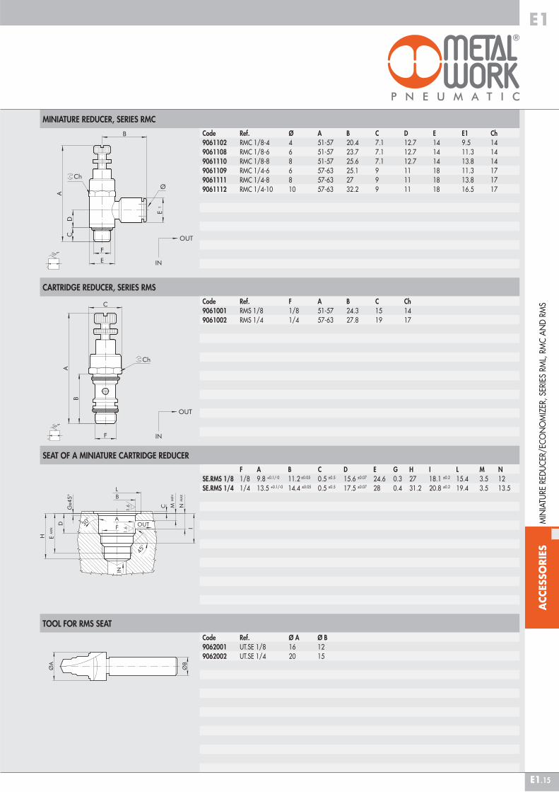
MINIATURE REDUCER, SERIES RMC
CARTRIDGE REDUCER, SERIES RMS
SEAT OF A MINIATURE CARTRIDGE REDUCER
TOOL FOR RMS SEAT
F A B C D E G H I L M NSE.RMS 1/8 1/8 9.8 +0.1/-0 11.2 ±0.05 0.5 ±0.5 15.6 ±0.07 24.6 0.3 27 18.1 ±0.2 15.4 3.5 12SE.RMS 1/4 1/4 13.5 +0.1/-0 14.4 ±0.05 0.5 ±0.5 17.5 ±0.07 28 0.4 31.2 20.8 ±0.2 19.4 3.5 13.5
MIN
IATU
RE R
EDU
CER
/EC
ON
OM
IZER
, SER
IES
RML,
RM
C A
ND
RM
S
Code Ref. Ø A B C D E E1 Ch9061102 RMC 1/8-4 4 51-57 20.4 7.1 12.7 14 9.5 149061108 RMC 1/8-6 6 51-57 23.7 7.1 12.7 14 11.3 149061110 RMC 1/8-8 8 51-57 25.6 7.1 12.7 14 13.8 149061109 RMC 1/4-6 6 57-63 25.1 9 11 18 11.3 179061111 RMC 1/4-8 8 57-63 27 9 11 18 13.8 179061112 RMC 1/4-10 10 57-63 32.2 9 11 18 16.5 17
Code Ref. F A B C Ch9061001 RMS 1/8 1/8 51-57 24.3 15 149061002 RMS 1/4 1/4 57-63 27.8 19 17
Code Ref. Ø A Ø B9062001 UT.SE 1/8 16 129062002 UT.SE 1/4 20 15

ACC
ESSO
RIES
E1
E1.16
The MAN L pressure gauge belongs to the LINE ON LINE® family, which means it can be connected to all the other components in series or in parallel.Available in the version for pipe-pipe connection with two push-in fittings, and in the version for thread-pipe connection with a brass nickel-plated male thread and a push-in fitting.Though small in size, this pressure gauge, which is supplied in a metal casing, ensures accurate reading. It can be angled in any direction simply by rotating manually.
TECHNICAL DATA
ASSEMBLY OPTIONS
Operating pressure MPa bar psiTemperature range °C °FPrecisionRecommended pipeFluidCompatibility with oils
Ø 4 Ø 6 Ø 8
1.212174
– 20 to + 60– 4 to + 140
± 4% full scaleRilsan PA11 - Nylon 6 - Polyamide 12 - Polypropylene
Lubricated or unlubricated filtered compressed airSee chapter Z1
IN-LINE PRESSURE GAUGE SERIES MAN L
IN-L
INE
PRES
SURE
GA
UG
E SE
RIES
MA
N L
� � �
How to mount the MAN L:• Fig. � With the male threaded port it is possible to mount the MAN L straight onto the female thread.• Fig. � Fixing to the plate with the special SQU L bracket.• Fig. � There are two robust rings on the plastic body for fixing the MAN L straight onto the wall.• Fig. � Use the SQL L bracket for panel mounting the MAN L.
�
#TAG_E1_00050

ACC
ESSO
RIES
E1
E1.17
MAN L PIPE-PIPE
MAN L THREAD-PIPE
Code Ref. F Ø P A A1 B C D E E1 E2 I I1 Ch9067101 MAN L M5-4 M5 4 4 47.7 26.7 36.1 10.7 5.6 9.9 10 23 12.8 16 99067102 MAN L 1/8-4 1/8 4 6 51.5 30.6 36.1 10.7 5.6 14 10 23 12.8 16 129067108 MAN L 1/8-6 1/8 6 6 58.5 27.8 35 14.7 6.4 14 11.4 23 14.6 20 129067109 MAN L 1/4-6 1/4 6 8 61.5 28.8 35 14.7 6.4 18 11.4 23 14.6 20 149067110 MAN L 1/8-8 1/8 8 6 66.2 31.8 41 18.7 9.1 15 13.8 23 18.7 24 149067111 MAN L 1/4-8 1/4 8 8 70.6 34.2 41 18.7 9.1 18 13.8 23 18.7 24 149067112 MAN L 3/8-8 3/8 8 9 72.2 34.8 41 18.7 9.1 22 13.8 23 18.7 24 17
Code Ref. Ø A B C D E E1 I I19067001 MAN L 4-4 4 41.8 36.1 10.7 5.6 10 23 12.8 169067016 MAN L 6-6 6 49.4 35 14.7 6.4 11.4 23 14.6 209067024 MAN L 8-8 8 57.3 41 18.7 9.1 13.8 23 18.7 24
NOTES
IN-L
INE
PRES
SURE
GA
UG
E SE
RIES
MA
N L
ACC
ESSO
RIES
E1
E1.18
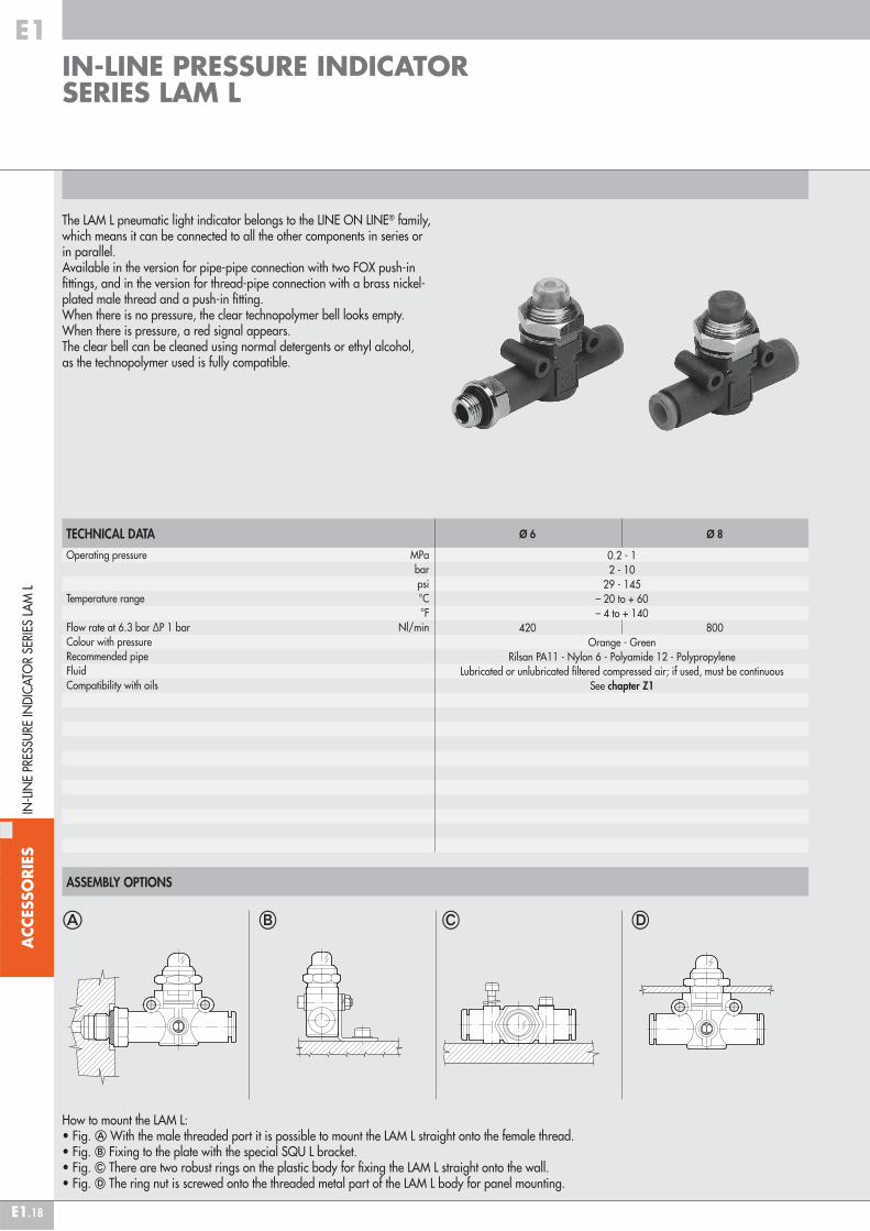
The LAM L pneumatic light indicator belongs to the LINE ON LINE® family, which means it can be connected to all the other components in series or in parallel.Available in the version for pipe-pipe connection with two FOX push-in fittings, and in the version for thread-pipe connection with a brass nickel-plated male thread and a push-in fitting.When there is no pressure, the clear technopolymer bell looks empty. When there is pressure, a red signal appears.The clear bell can be cleaned using normal detergents or ethyl alcohol, as the technopolymer used is fully compatible.
TECHNICAL DATA
ASSEMBLY OPTIONS
Operating pressure MPa bar psiTemperature range °C °FFlow rate at 6.3 bar ΔP 1 bar Nl/minColour with pressureRecommended pipeFluidCompatibility with oils
Ø 6 Ø 8
0.2 - 12 - 10
29 - 145– 20 to + 60– 4 to + 140
420 800Orange - Green
Rilsan PA11 - Nylon 6 - Polyamide 12 - PolypropyleneLubricated or unlubricated filtered compressed air; if used, must be continuous
See chapter Z1
IN-LINE PRESSURE INDICATOR SERIES LAM L
IN-L
INE
PRES
SURE
IND
ICA
TOR
SERI
ES L
AM
L
� � �
How to mount the LAM L:• Fig. � With the male threaded port it is possible to mount the LAM L straight onto the female thread.• Fig. � Fixing to the plate with the special SQU L bracket.• Fig. � There are two robust rings on the plastic body for fixing the LAM L straight onto the wall.• Fig. � The ring nut is screwed onto the threaded metal part of the LAM L body for panel mounting.
�
#TAG_E1_00060

ACC
ESSO
RIES
E1
E1.19
LAM L PIPE-PIPE
LAM L THREAD-PIPE
Code Ref. F Ø P A A1 B C D E E1 E2 G H I I1 Ch Ch1 Nmax9068108 LAM L 1/8-6-A 1/8 6 6 58.5 27.8 37 14.7 6.4 14 11.4 10.6 21 M15x1 14.6 20 17 12 4.59068308 LAM L 1/8-6-V9068109 LAM L 1/4-6-A 1/4 6 8 61.5 28.8 37 14.7 6.4 18 11.4 10.6 21 M15x1 14.6 20 17 14 4.59068309 LAM L 1/4-6-V9068110 LAM L 1/8-8-A 1/8 8 6 66.2 31.8 41 18.7 9.1 15 13.8 10.6 26 M15x1 18.7 24 17 14 4.59068310 LAM L 1/8-8-V9068111 LAM L 1/4-8-A 1/4 8 8 70.6 34.2 41 18.7 9.1 18 13.8 10.6 26 M15x1 18.7 24 17 14 4.59068311 LAM L 1/4-8-V9068112 LAM L 3/8-8-A 3/8 8 9 72.2 34.8 41 18.7 9.1 22 13.8 10.6 26 M15x1 18.7 24 17 17 4.59068312 LAM L 3/8-8-V
A = OrangeV = Green
Code Ref. Ø A B C D E E1 G H I I1 Ch Nmax9068016 LAM L 6-6-A 6 49.4 37 14.7 6.4 11.4 10.6 21 M15x1 14.6 20 17 4.59068216 LAM L 6-6-V9068024 LAM L 8-8-A 8 57.3 41 18.7 9.1 13.8 10.6 26 M15x1 18.7 24 17 4.59068224 LAM L 8-8-V
A = OrangeV = Green
IN-L
INE
PRES
SURE
IND
ICA
TOR
SERI
ES L
AM
L
ACC
ESSO
RIES
E1
E1.20
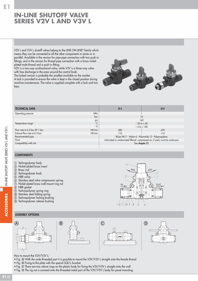
V2V L and V3V L shutoff valves belong to the LINE ON LINE® family which means they can be connected to all the other components in series or in parallel. Available in the version for pipe-pipe connection with two push-in fittings, and in the version for thread-pipe connection with a brass nickel-plated male thread and a push-in fitting.V2V is a two-way unidirectional valve, while V3V is a three-way valve with free discharge in the area around the control knob. The locked version is probably the smallest available on the market. A lock is provided to ensure the valve is kept in the closed position during machine maintenance. The valve is supplied complete with a lock and two keys.
TECHNICAL DATA
ASSEMBLY OPTIONS
Ø 6 Ø 8
110145
– 20 to + 60– 4 to + 140
280 470 110 110
Rilsan PA11 - Nylon 6 - Polyamide 12 - PolypropyleneLubricated or unlubricated filtered compressed air; if used, must be continuous
See chapter Z1
IN-LINE SHUTOFF VALVE SERIES V2V L AND V3V L
IN-L
INE
SHU
TOFF
VA
LVE
SERI
ES V
2V L
AN
D V
3V L
� � �
How to mount the V2V/V3V L:• Fig. � With the male threaded port it is possible to mount the V2V/V3V L straight onto the female thread.• Fig. � Fixing to the plate with the special SQU L bracket.• Fig. � There are two robust rings on the plastic body for fixing the V2V/V3V L straight onto the wall.• Fig. � The rig nut is screwed onto the threaded metal part of the V2V/V3V L body for panel mounting.
�
COMPONENTS
� Technopolymer body� Nickel-plated brass insert� Brass rod� Technopolymer knob� NBR valve� Stainless steel valve compression spring� Nickel-plated brass wall-mount ring nut NBR gasket Technopolymer spring ring� Stainless steel folding spring� Technopolymer locking bushing Technopolymer release bushing
Operating pressure MPa bar psiTemperature range °C °FFlow rate at 6.3 bar ΔP 1 bar Nl/minExhaust flow rate at 6.3 bar Nl/minRecommended pipeFluidCompatibility with oils
#TAG_E1_00070

ACC
ESSO
RIES
E1
E1.21
V2V/V3V L PIPE-PIPE
V2V/V3V L PIPE-PIPE PADLOCKED
V2V/V3V L PIPE-THREAD
IN-L
INE
SHU
TOFF
VA
LVE
SERI
ES V
2V L
AN
D V
3V L
Code Ref. Ø F P A A1 B C D E E1 G H I I1 Ch Ch1 Nmax9065208 V2V L 6-1/8 6 1/8 6 58.5 27.8 41 14.7 6.4 14 11.4 21 M15x1 14.6 20 17 12 5.59066208 V3V L 6-1/89065209 V2V L 6-1/4 6 1/4 8 61.5 28.8 41 14.7 6.4 18 11.4 21 M15x1 14.6 20 17 14 5.59066209 V3V L 6-1/49065210 V2V L 8-1/8 8 1/8 6 66.2 31.8 46 18.7 9.1 15 13.8 26 M15x1 18.7 24 17 14 5.59066210 V3V L 8-1/89065211 V2V L 8-1/4 8 1/4 8 70.6 34.2 46 18.7 9.1 18 13.8 26 M15x1 18.7 24 17 14 5.59066211 V3V L 8-1/49065212 V2V L 8-3/8 8 3/8 9 72.2 34.8 46 18.7 9.1 22 13.8 26 M15x1 18.7 24 17 17 5.59066212 V3V L 8-3/8
Code Ref. Ø A B C D E G H I I1 Ch Nmax9065116 V2V L 6-6 KEY 6 49.4 41 14.7 6.4 11.4 21 M15x1 14.6 20 17 5.59066116 V3V L 6-6 KEY9065124 V2V L 8-8 KEY 8 57.3 46 18.7 9.1 13.8 26 M15x1 18.7 24 17 5.59066124 V3V L 8-8 KEY
Code Ref. Ø A B C D E G H I I1 Ch Nmax9065016 V2V L 6-6 6 49.4 41 14.7 6.4 11.4 21 M15x1 14.6 20 17 5.59066016 V3V L 6-69065024 V2V L 8-8 8 57.3 46 18.7 9.1 13.8 26 M15x1 18.7 24 17 5.59066024 V3V L 8-8

ACC
ESSO
RIES
E1
E1.22
V2V/V3V L PIPE-THREAD PADLOCKED
V2V/V3V L THREAD-PIPE
V2V/V3V L THREAD-PIPE PADLOCKED
Code Ref. Ø F P A A1 B C D E E1 G H I I1 Ch Ch1 Nmax9065308 V2V L 6-1/8 KEY 6 1/8 6 58.5 27.8 41 14.7 6.4 14 11.4 21 M15x1 14.6 20 17 12 5.59066308 V3V L 6-1/8 KEY9065309 V2V L 6-1/4 KEY 6 1/4 8 61.5 28.8 41 14.7 6.4 18 11.4 21 M15x1 14.6 20 17 14 5.59066309 V3V L 6-1/4 KEY9065310 V2V L 8-1/8 KEY 8 1/8 6 66.2 31.8 46 18.7 9.1 15 13.8 26 M15x1 18.7 24 17 14 5.59066310 V3V L 8-1/8 KEY9065311 V2V L 8-1/4 KEY 8 1/4 8 70.6 34.2 46 18.7 9.1 18 13.8 26 M15x1 18.7 24 17 14 5.59066311 V3V L 8-1/4 KEY9065312 V2V L 8-3/8 KEY 8 3/8 9 72.2 34.8 46 18.7 9.1 22 13.8 26 M15x1 18.7 24 17 17 5.59066312 V3V L 8-3/8 KEY
Code Ref. F Ø P A A1 B C D E E1 G H I I1 Ch Ch1 Nmax9065408 V2V L 1/8-6 1/8 6 6 58.5 27.8 41 14.7 6.4 14 11.4 21 M15x1 14.6 20 17 12 5.59066408 V3V L 1/8-69065409 V2V L 1/4-6 1/4 6 8 61.5 28.8 41 14.7 6.4 18 11.4 21 M15x1 14.6 20 17 14 5.59066409 V3V L 1/4-69065410 V2V L 1/8-8 1/8 8 6 66.2 31.8 46 18.7 9.1 15 13.8 26 M15x1 18.7 24 17 14 5.59066410 V3V L 1/8-89065411 V2V L 1/4-8 1/4 8 8 70.6 34.2 46 18.7 9.1 18 13.8 26 M15x1 18.7 24 17 14 5.59066411 V3V L 1/4-89065412 V2V L 3/8-8 3/8 8 9 72.2 34.8 46 18.7 9.1 22 13.8 26 M15x1 18.7 24 17 17 5.59066412 V3V L 3/8-8
Code Ref. F Ø P A A1 B C D E E1 G H I I1 Ch Ch1 Nmax9065508 V2V L 1/8-6 KEY 1/8 6 6 58.5 27.8 41 14.7 6.4 14 11.4 21 M15x1 14.6 20 17 12 5.59066508 V3V L 1/8-6 KEY9065509 V2V L 1/4-6 KEY 1/4 6 8 61.5 28.8 41 14.7 6.4 18 11.4 21 M15x1 14.6 20 17 14 5.59066509 V3V L 1/4-6 KEY9065510 V2V L 1/8-8 KEY 1/8 8 6 66.2 31.8 46 18.7 9.1 15 13.8 26 M15x1 18.7 24 17 14 5.59066510 V3V L 1/8-8 KEY9065511 V2V L 1/4-8 KEY 1/4 8 8 70.6 34.2 46 18.7 9.1 18 13.8 26 M15x1 18.7 24 17 14 5.59066511 V3V L 1/4-8 KEY9065512 V2V L 3/8-8 KEY 3/8 8 9 72.2 34.8 46 18.7 9.1 22 13.8 26 M15x1 18.7 24 17 17 5.59066512 V3V L 3/8-8 KEY
IN-L
INE
SHU
TOFF
VA
LVE
SERI
ES V
2V L
AN
D V
3V L

ACC
ESSO
RIES
E1
E1.23
The RLF L flow micro-regulator belongs to the LINE ON LINE® family and can be connected in series or in parallel with all the other products.The RFL L regulates the air input and thus the speed in pneumatic actuators. Two versions are available:Type U (unidirectional) regulates the flow only in one of the two directions of air flow. The following types of fitting can be mounted:• Push-in input and output fitting• Push-in input fitting and threaded port on the exhaust (cylinder type)• Input threaded port and push-in fitting on the exhaust (valve type)Type B (bidirectional) regulates the flow in both directions of air flow. The following types of fitting can be mounted:• Push-in input and output fitting• Threaded port and push-in fittingThere are four possible types of assembly (see example below).
TECHNICAL DATA
ASSEMBLY OPTIONS
Max. operating pressure MPa bar psiTemperature range °C °FMax flow rate on regulation at 6.3 bar Nl/minFlow rate on exhaust at 6.3 bar Nl/minAdjustmentInternal systemRecommended pipeFluidCompatibility with oils
Ø 4 Ø 6 Ø 8
110145
– 20 to + 60– 4 to + 140
155 450 850 160 550 950
Manual or using a screwdriverTapered needle
Rilsan PA 11 - Nylon 6 - Polyamide 12 - PolypropyleneLubricated or unlubricated filtered air
See chapter Z1
� � �
How to mount the RFL L:• Fig. � With the male threaded port it is possible to mount the RFL L straight onto the actuator or the control valve.• Fig. � Fixing to the plate with the special SQU L bracket.• Fig. � There are two robust rings on the plastic body for fixing the RFL L straight onto the wall.• Fig. � The ring nut is screwed onto the threaded metal part of the RFL L body for panel mounting.
�
COMPONENTS
� Technopolymer body� Nickel-plated brass seal support� NBR gasket� Brass adjusting needle� Nickel-plated brass needle ring nut� Wall fixing ring nut� NBR seal Technopolymer spring ring Stainless steel clip-on spring� Technopolymer stop bushing� Technopolymer release bushing
IN-LINE FLOW MICRO-REGULATOR SERIES RFL L
IN-L
INE
FLO
W M
ICRO
-REG
ULA
TOR
SERI
E RF
L L
UNIDIRECTIONAL BIDIRECTIONAL
#TAG_E1_00080
ACC
ESSO
RIES
E1
E1.24
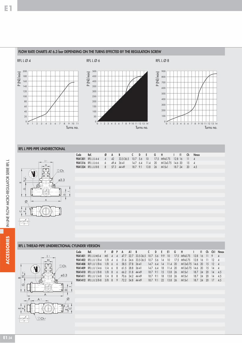
FLOW RATE CHARTS AT 6.3 bar DEPENDING ON THE TURNS EFFECTED BY THE REGULATION SCREW
RFL L PIPE-PIPE UNIDIRECTIONAL
RFL L THREAD-PIPE UNIDIRECTIONAL CYLINDER VERSION
Code Ref. F Ø P A A1 B C D E E1 G H I I1 Ch Ch1 Nmax9041401 RFL L U M5-4 M5 4 4 47.7 22.7 33.5-36.5 10.7 5.6 9.9 10 17.5 M9x0.75 12.8 16 11 9 49041402 RFL L U 1/8-4 1/8 4 6 51.6 24.6 33.5-36.5 10.7 5.6 14 10 17.5 M9x0.75 12.8 16 11 12 49041408 RLF L U 1/8-6 1/8 6 6 58.5 27.8 36-41 14.7 6.4 14 11.4 20 M12x0.75 14.6 20 15 12 49041409 RFL L U 1/4-6 1/4 6 8 61.5 28.8 36-41 14.7 6.4 18 11.4 20 M12x0.75 14.6 20 15 14 49041410 RFL L U 1/8-8 1/8 8 6 66.2 31.8 44-49 18.7 9.1 15 13.8 26 M15x1 18.7 24 20 14 4.59041411 RFL L U 1/4-8 1/4 8 8 70.6 34.2 44-49 18.7 9.1 18 13.8 26 M15x1 18.7 24 20 14 4.59041412 RFL L U 3/8-8 3/8 8 9 72.2 34.8 44-49 18.7 9.1 22 13.8 26 M15x1 18.7 24 20 17 4.5
IN-L
INE
FLO
W M
ICRO
-REG
ULA
TOR
SERI
E RF
L L
RFL L Ø 4 RFL L Ø 6 RFL L Ø 8
P (N
l/m
in)
Turns no. Turns no. Turns no.
Code Ref. Ø A B C D E G H I I1 Ch Nmax9041301 RFL L U 4-4 4 42 33.5-36.5 10.7 5.6 10 17.5 M9x0.75 12.8 16 11 49041316 RFL L U 6-6 6 49.4 36-41 14.7 6.4 11.4 20 M12x0.75 14.6 20 15 49041324 RFL L U 8-8 8 57.3 44-49 18.7 9.1 13.8 26 M15x1 18.7 24 20 4.5
P (N
l/m
in)
P (N
l/m
in)
ACC
ESSO
RIES
E1
E1.25
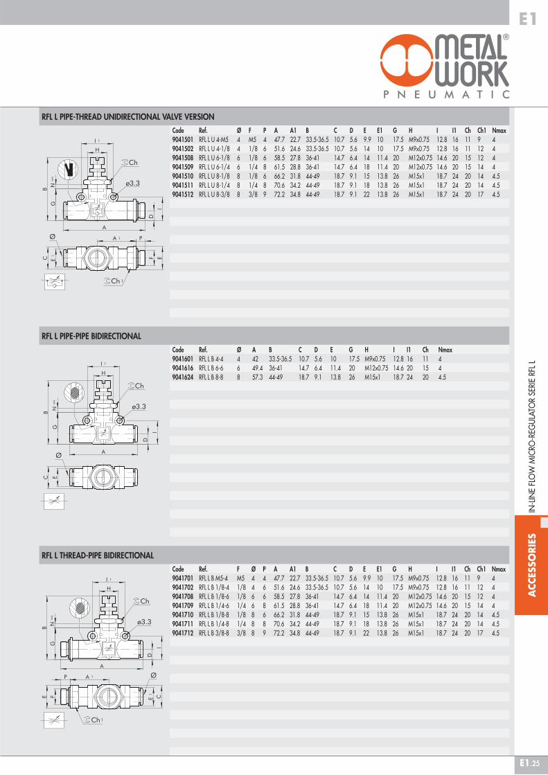
RFL L PIPE-THREAD UNIDIRECTIONAL VALVE VERSION
RFL L PIPE-PIPE BIDIRECTIONAL
RFL L THREAD-PIPE BIDIRECTIONAL
IN-L
INE
FLO
W M
ICRO
-REG
ULA
TOR
SERI
E RF
L L
Code Ref. Ø F P A A1 B C D E E1 G H I I1 Ch Ch1 Nmax9041501 RFL L U 4-M5 4 M5 4 47.7 22.7 33.5-36.5 10.7 5.6 9.9 10 17.5 M9x0.75 12.8 16 11 9 49041502 RFL L U 4-1/8 4 1/8 6 51.6 24.6 33.5-36.5 10.7 5.6 14 10 17.5 M9x0.75 12.8 16 11 12 49041508 RFL L U 6-1/8 6 1/8 6 58.5 27.8 36-41 14.7 6.4 14 11.4 20 M12x0.75 14.6 20 15 12 49041509 RFL L U 6-1/4 6 1/4 8 61.5 28.8 36-41 14.7 6.4 18 11.4 20 M12x0.75 14.6 20 15 14 49041510 RFL L U 8-1/8 8 1/8 6 66.2 31.8 44-49 18.7 9.1 15 13.8 26 M15x1 18.7 24 20 14 4.59041511 RFL L U 8-1/4 8 1/4 8 70.6 34.2 44-49 18.7 9.1 18 13.8 26 M15x1 18.7 24 20 14 4.59041512 RFL L U 8-3/8 8 3/8 9 72.2 34.8 44-49 18.7 9.1 22 13.8 26 M15x1 18.7 24 20 17 4.5
Code Ref. Ø A B C D E G H I I1 Ch Nmax9041601 RFL L B 4-4 4 42 33.5-36.5 10.7 5.6 10 17.5 M9x0.75 12.8 16 11 49041616 RFL L B 6-6 6 49.4 36-41 14.7 6.4 11.4 20 M12x0.75 14.6 20 15 49041624 RFL L B 8-8 8 57.3 44-49 18.7 9.1 13.8 26 M15x1 18.7 24 20 4.5
Code Ref. F Ø P A A1 B C D E E1 G H I I1 Ch Ch1 Nmax9041701 RFL L B M5-4 M5 4 4 47.7 22.7 33.5-36.5 10.7 5.6 9.9 10 17.5 M9x0.75 12.8 16 11 9 49041702 RFL L B 1/8-4 1/8 4 6 51.6 24.6 33.5-36.5 10.7 5.6 14 10 17.5 M9x0.75 12.8 16 11 12 49041708 RFL L B 1/8-6 1/8 6 6 58.5 27.8 36-41 14.7 6.4 14 11.4 20 M12x0.75 14.6 20 15 12 49041709 RFL L B 1/4-6 1/4 6 8 61.5 28.8 36-41 14.7 6.4 18 11.4 20 M12x0.75 14.6 20 15 14 49041710 RFL L B 1/8-8 1/8 8 6 66.2 31.8 44-49 18.7 9.1 15 13.8 26 M15x1 18.7 24 20 14 4.59041711 RFL L B 1/4-8 1/4 8 8 70.6 34.2 44-49 18.7 9.1 18 13.8 26 M15x1 18.7 24 20 14 4.59041712 RFL L B 3/8-8 3/8 8 9 72.2 34.8 44-49 18.7 9.1 22 13.8 26 M15x1 18.7 24 20 17 4.5
ACC
ESSO
RIES
E1
E1.26
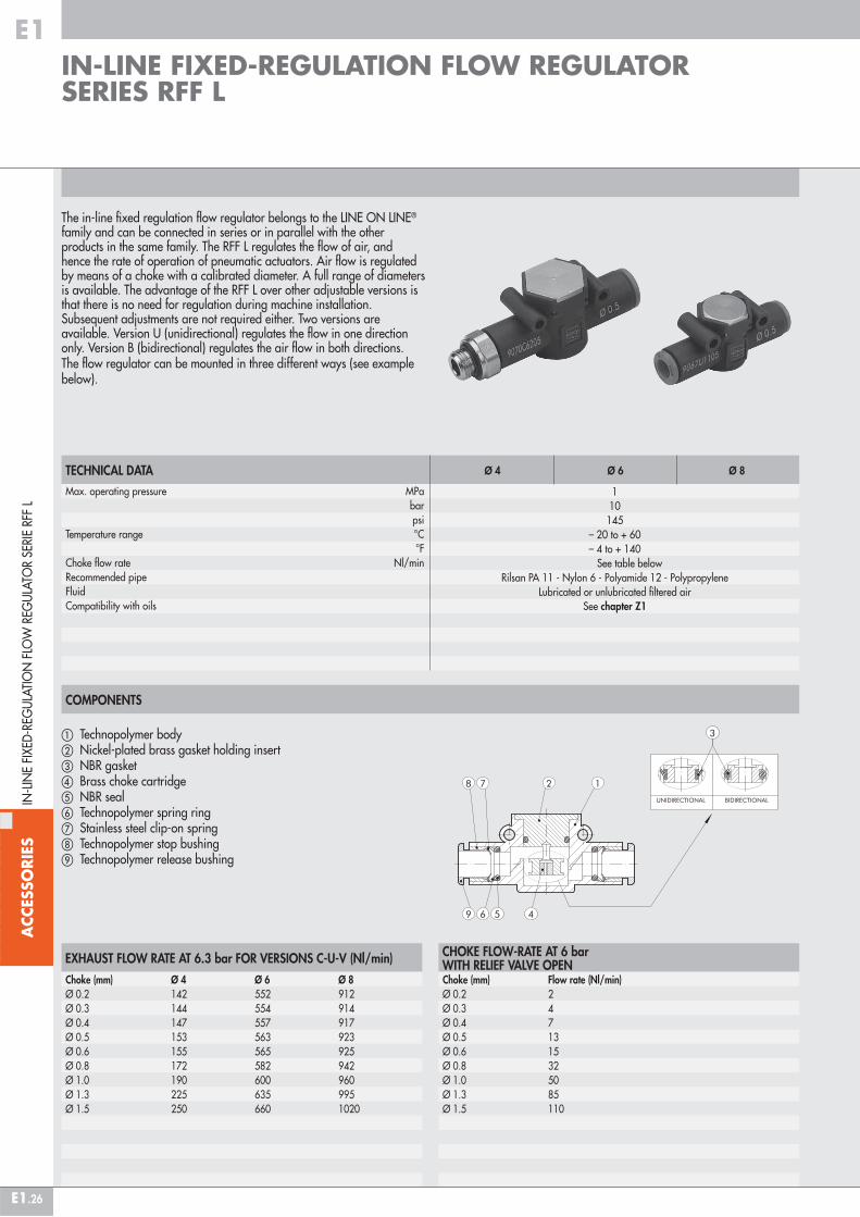
The in-line fixed regulation flow regulator belongs to the LINE ON LINE® family and can be connected in series or in parallel with the other products in the same family. The RFF L regulates the flow of air, and hence the rate of operation of pneumatic actuators. Air flow is regulated by means of a choke with a calibrated diameter. A full range of diameters is available. The advantage of the RFF L over other adjustable versions is that there is no need for regulation during machine installation. Subsequent adjustments are not required either. Two versions are available. Version U (unidirectional) regulates the flow in one direction only. Version B (bidirectional) regulates the air flow in both directions. The flow regulator can be mounted in three different ways (see example below).
COMPONENTS
� Technopolymer body� Nickel-plated brass gasket holding insert � NBR gasket� Brass choke cartridge� NBR seal� Technopolymer spring ring� Stainless steel clip-on spring Technopolymer stop bushing Technopolymer release bushing
EXHAUST FLOW RATE AT 6.3 bar FOR VERSIONS C-U-V (Nl/min)
Choke (mm) Ø 4 Ø 6 Ø 8Ø 0.2 142 552 912Ø 0.3 144 554 914Ø 0.4 147 557 917Ø 0.5 153 563 923Ø 0.6 155 565 925Ø 0.8 172 582 942Ø 1.0 190 600 960Ø 1.3 225 635 995Ø 1.5 250 660 1020
CHOKE FLOW-RATE AT 6 bar WITH RELIEF VALVE OPENChoke (mm) Flow rate (Nl/min)Ø 0.2 2Ø 0.3 4Ø 0.4 7Ø 0.5 13Ø 0.6 15Ø 0.8 32Ø 1.0 50Ø 1.3 85Ø 1.5 110
TECHNICAL DATAMax. operating pressure MPa bar psiTemperature range °C °FChoke flow rate Nl/minRecommended pipeFluidCompatibility with oils
Ø 4 Ø 6 Ø 8
110145
– 20 to + 60– 4 to + 140
See table belowRilsan PA 11 - Nylon 6 - Polyamide 12 - Polypropylene
Lubricated or unlubricated filtered airSee chapter Z1
IN-LINE FIXED-REGULATION FLOW REGULATOR SERIES RFF L
IN-L
INE
FIXE
D-R
EGU
LATI
ON
FLO
W R
EGU
LATO
R SE
RIE
RFF
L
#TAG_E1_00090

ACC
ESSO
RIES
E1
E1.27
RFF L PIPE - PIPE UNIDIRECTIONAL
RFF L THREAD - PIPE UNIDIRECTIONAL CYLINDER VERSION
RFF L PIPE - THREAD UNIDIRECTIONAL VALVE VERSION
Code Ref. F Ø P A A1 B C E E1 I I1 Ch19070C51_ _* RFF-C L M5 - Ø4 M5 4 4 47.7 22.7 17.5 10.7 9.9 10 12.8 16 99070C61_ _* RFF-C L 1/8" - Ø4 1/8 4 6 51.6 24.6 17.5 10.7 14 10 12.8 16 129070C62_ _* RFF-C L 1/8" - Ø6 1/8 6 6 58.5 27.8 20 14.7 14 11.4 14.6 20 129070C72_ _* RFF-C L 1/4" - Ø6 1/4 6 8 61.5 28.8 20 14.7 18 11.4 14.6 20 149070C63_ _* RFF-C L 1/8" - Ø8 1/8 8 6 66.2 31.8 25.5 18.7 15 13.8 18.7 24 149070C73_ _* RFF-C L 1/4" - Ø8 1/4 8 8 70.6 34.2 25.5 18.7 18 13.8 18.7 24 149070C83_ _* RFF-C L 3/8" - Ø8 3/8 8 9 72.2 34.8 25.5 18.7 22 13.8 18.7 24 17
* The last two digits indicate the narrowing Ø. To complete the code please look at the key to codes.
Code Ref. Ø A B C D E I I19070U11_ _* RFF-U L 4-4 4 42 17.5 10.7 5.6 10 12.8 169070U22_ _* RFF-U L 6-6 6 49.4 20 14.7 6.4 11.4 14.6 209070U33_ _* RFF-U L 8-8 8 57.3 25.5 18.7 9.1 13.8 18.7 24
* The last two digits indicate the narrowing Ø. To complete the code please look at the key to codes.
Code Ref. Ø F P A A1 B C E E1 I I1 Ch19070V15_ _* RFF-V L Ø4 - M5 4 M5 4 47.7 22.7 17.5 10.7 9.9 10 12.8 16 99070V16_ _* RFF-V L Ø4 - 1/8" 4 1/8 6 51.6 24.6 17.5 10.7 14 10 12.8 16 129070V26_ _* RFF-V L Ø6 - 1/8" 6 1/8 6 58.5 27.8 20 14.7 14 11.4 14.6 20 129070V27_ _* RFF-V L Ø6 - 1/4" 6 1/4 8 61.5 28.8 20 14.7 18 11.4 14.6 20 149070V36_ _* RFF-V L Ø8 - 1/8" 8 1/8 6 66.2 31.8 25.5 18.7 15 13.8 18.7 24 149070V37_ _* RFF-V L Ø8 - 1/4" 8 1/4 8 70.6 34.2 25.5 18.7 18 13.8 18.7 24 149070V38_ _* RFF-V L Ø8 - 3/8" 8 3/8 9 72.2 34.8 25.5 18.7 22 13.8 18.7 24 17
* The last two digits indicate the narrowing Ø. To complete the code please look at the key to codes.
ASSEMBLY OPTIONS
� �
How to mount the RFF L:• Fig. � With the male threaded port it is possible to mount the RFF L straight onto the actuator or the control valve.• Fig. � Fixing to the plate with the special SQU L bracket.• Fig. � There are two robust rings on the plastic body for fixing the RFF L straight onto the wall.
�
IN-L
INE
FIXE
D-R
EGU
LATI
ON
FLO
W R
EGU
LATO
R SE
RIE
RFF
L

ACC
ESSO
RIES
E1
E1.28
RFF L PIPE - PIPE BIDIRECTIONAL
RFF L THREAD - PIPE BIDIRECTIONAL
KEY TO CODES
Code Ref. Ø A B C D E I I19070B11_ _* RFF-B L 4-4 4 42 17.5 10.7 5.6 10 12.8 169070B22_ _* RFF-B L 6-6 6 49.4 20 14.7 6.4 11.4 14.6 209070B33_ _* RFF-B L 8-8 8 57.3 25.5 18.7 9.1 13.8 18.7 24
* The last two digits indicate the narrowing Ø. To complete the code please look at the key to codes.
IN-L
INE
FIXE
D-R
EGU
LATI
ON
FLO
W R
EGU
LATO
R SE
RIE
RFF
L
Code Ref. F Ø P A A1 B C E E1 I I1 Ch19070B51_ _* RFF-B L M5 - Ø 4 M5 4 4 47.7 22.7 17.5 10.7 9.9 10 12.8 16 99070B61_ _* RFF-B L 1/8" - Ø 4 1/8 4 6 51.6 24.6 17.5 10.7 14 10 12.8 16 129070B62_ _* RFF-B L 1/8" - Ø 6 1/8 6 6 58.5 27.8 20 14.7 14 11.4 14.6 20 129070B72_ _* RFF-B L 1/4" - Ø 6 1/4 6 8 61.5 28.8 20 14.7 18 11.4 14.6 20 149070B63_ _* RFF-B L 1/8" - Ø 8 1/8 8 6 66.2 31.8 25.5 18.7 15 13.8 18.7 24 149070B73_ _* RFF-B L 1/4" - Ø 8 1/4 8 8 70.6 34.2 25.5 18.7 18 13.8 18.7 24 149070B83_ _* RFF-B L 3/8" - Ø 8 3/8 8 9 72.2 34.8 25.5 18.7 22 13.8 18.7 24 17
* The last two digits indicate the narrowing Ø. To complete the code please look at the key to codes.
9 0 7 0 B 11 02TYPE FUNCTION Ø IN - Ø OUT Ø CHOKE
9070 RFF L B BidirectionalC For cylinderU UnidirectionalV For valve
11 = Ø 4 - Ø 4 15 = Ø 4 - M5 16 = Ø 4 - 1/8” 22 = Ø 6 - Ø 6 26 = Ø 6 - 1/8” 27 = Ø 6 - 1/4” 33 = Ø 8 - Ø 8 36 = Ø 8 - 1/8” 37 = Ø 8 - 1/4” 38 = Ø 8 - 3/8” 51 = M5 - Ø 4 61 = 1/8” - Ø 4 62 = 1/8” - Ø 6 63 = 1/8” - Ø 8 72 = 1/4” - Ø 6 73 = 1/4” - Ø 8 83 = 3/8” - Ø 8
02 = Ø 0.2 03 = Ø 0.3 04 = Ø 0.4 05 = Ø 0.5 06 = Ø 0.6 08 = Ø 0.8 10 = Ø 1.0 13 = Ø 1.3 15 = Ø 1.5
Only for B (bidirectional) and U (unidirectional) versions Only for V (valve) versions Only for C (cylinder) and B (bidirectional) versions
ACC
ESSO
RIES
E1
E1.29
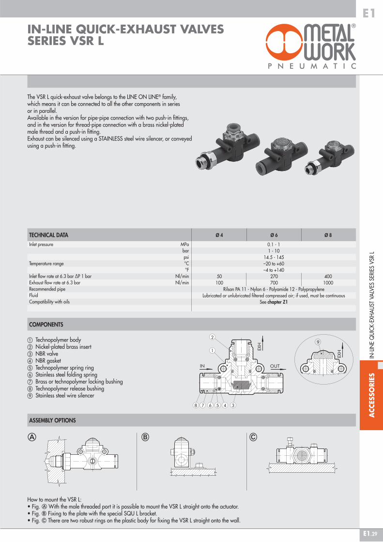
The VSR L quick-exhaust valve belongs to the LINE ON LINE® family, which means it can be connected to all the other components in series or in parallel.Available in the version for pipe-pipe connection with two push-in fittings, and in the version for thread-pipe connection with a brass nickel-plated male thread and a push-in fitting.Exhaust can be silenced using a STAINLESS steel wire silencer, or conveyed using a push-in fitting.
TECHNICAL DATA
ASSEMBLY OPTIONS
Inlet pressure MPa bar psiTemperature range °C °FInlet flow rate at 6.3 bar ΔP 1 bar Nl/minExhaust flow rate at 6.3 bar Nl/minRecommended pipeFluidCompatibility with oils
Ø 4 Ø 6 Ø 8
0.1 - 11 - 10
14.5 - 145–20 to +60–4 to +140
50 270 400 100 700 1000
Rilsan PA 11 - Nylon 6 - Polyamide 12 - PolypropyleneLubricated or unlubricated filtered compressed air; if used, must be continuous
See chapter Z1
� �
How to mount the VSR L:• Fig. � With the male threaded port it is possible to mount the VSR L straight onto the actuator.• Fig. � Fixing to the plate with the special SQU L bracket.• Fig. � There are two robust rings on the plastic body for fixing the VSR L straight onto the wall.
�
COMPONENTS
� Technopolymer body� Nickel-plated brass insert� NBR valve� NBR gasket� Technopolymer spring ring� Stainless steel folding spring� Brass or technopolymer locking bushing Technopolymer release bushing Stainless steel wire silencer
IN-LINE QUICK-EXHAUST VALVES SERIES VSR L
IN-L
INE
QU
ICK
-EXH
AU
ST V
ALV
ES S
ERIE
S V
SR L
#TAG_E1_00100

ACC
ESSO
RIES
E1
E1.30
VSR L PIPE-PIPE, CONVEYED EXHAUST
VSR L PIPE-PIPE, SILENCED EXHAUST
VSR L PIPE-THREAD, CONVEYED EXHAUST
VSR L PIPE-THREAD, SILENCED EXHAUST
Code Ref. Ø F P A A1 B C D E E1 E2 I I1 Ch9063301 VSR L 4-M5-SIL 4 M5 4 46.7 22.7 19.8 10.7 5.6 9.9 10 10 12.8 16 99063302 VSR L 4-1/8-SIL 4 1/8 6 50.6 24.6 19.8 10.7 5.6 14 10 10 12.8 16 129063308 VSR L 6-1/8-SIL 6 1/8 6 58.5 27.8 25.5 14.7 6.4 14 11.4 14 14.6 20 129063309 VSR L 6-1/4-SIL 6 1/4 8 61.5 28.8 25.5 14.7 6.4 18 11.4 14 14.6 20 149063310 VSR L 8-1/8-SIL 8 1/8 6 66.2 31.8 31.5 18.7 9.1 15 13.8 18 18.7 24 149063311 VSR L 8-1/4-SIL 8 1/4 8 70.6 34.2 31.5 18.7 9.1 18 13.8 18 18.7 24 149063312 VSR L 8-3/8-SIL 8 3/8 9 72.2 34.8 31.5 18.7 9.1 22 13.8 18 18.7 24 17
IN-L
INE
QU
ICK
-EXH
AU
ST V
ALV
ES S
ERIE
S V
SR L
Code Ref. Ø F P A A1 B C D E E1 E2 I I1 Ch9063201 VSR L 4-M5-4 4 M5 4 47.7 22.7 25.8 10.7 5.6 9.9 10 9.7 12.8 16 99063202 VSR L 4-1/8-4 4 1/8 6 50.6 24.6 25.8 10.7 5.6 14 10 9.7 12.8 16 129063208 VSR L 6-1/8-6 6 1/8 6 58.5 27.8 30.2 14.7 6.4 14 11.4 13 14.6 20 129063209 VSR L 6-1/4-6 6 1/4 8 61.5 28.8 30.2 14.7 6.4 18 11.4 13 14.6 20 149063210 VSR L 8-1/8-8 8 1/8 6 66.2 31.8 35.9 18.7 9.1 15 13.8 15 18.7 24 149063211 VSR L 8-1/4-8 8 1/4 8 70.6 34.2 35.9 18.7 9.1 18 13.8 15 18.7 24 149063212 VSR L 8-3/8-8 8 3/8 9 72.2 34.8 35.9 18.7 9.1 22 13.8 15 18.7 24 17
Code Ref. Ø A B C D E E1 I I19063101 VSR L 4-4-SIL 4 41.8 19.8 10.7 5.6 10 10 12.8 169063116 VSR L 6-6-SIL 6 49.4 25.5 14.7 6.4 11.4 14 14.6 209063124 VSR L 8-8-SIL 8 57.3 31.5 18.7 9.1 13.8 18 18.7 24
Code Ref. Ø A B C D E E1 I I19063001 VSR L 4-4-4 4 41.8 25.8 10.7 5.6 10 9.7 12.8 169063016 VSR L 6-6-6 6 49.4 30.2 14.7 6.4 11.4 13 14.6 209063024 VSR L 8-8-8 8 57.3 35.9 18.7 9.1 13.8 15 18.7 24

ACC
ESSO
RIES
E1
E1.31
The VSRR L quick-exhaust valve with regulated exhaust belongs to the LINE ON LINE® family of products and can be linked in series or in parallel to all the other products. It comes in a version for pipe-pipe connection, which includes two push-in fittings, and a version for thread-pipe connection, which includes a nickel-plated brass taper thread and push-in fitting. The main feature of these valves is that the discharge flow can be adjusted via a pin regulator. This allows you to control the speed of the actuator connected to the valve, giving a higher speed than with an MRF regulator.
TECHNICAL DATAMax. operating pressure MPa bar psiTemperature range °C °FMax flow rate on regulation at 6.3 bar ΔP 1 bar Nl/minFlow rate on exhaust at 6.3 bar Nl/minAdjustmentInternal systemRecommended pipeFluidCompatibility with oils
Ø 4 Ø 6 Ø 8
110145
–20 to +60–4 to +140
50 270 400 170 460 960
Manual or using a screwdriverTapered needle
Rilsan PA 11 - Nylon 6 - Polyamide 12 - PolypropyleneLubricated or unlubricated filtered air
See chapter Z1
COMPONENTS
� Technopolymer body� Nickel-plated brass seal support� NBR gasket� Brass adjusting needle� Nickel-plated brass needle ring nut� Nickel-plated brass wall fixing ring nut� NBR seal Technopolymer spring ring Stainless steel clip-on spring� Technopolymer stop bushing� Technopolymer release bushing Sintered bronze silencer
IN-LINE QUICK-EXHAUST VALVE WITH REGULATED EXHAUST SERIES VSRR L
IN-L
INE
QU
ICK
-EXH
AU
ST V
ALV
E W
ITH
REG
ULA
TED
EXH
AU
ST S
ERIE
S V
SRR
L
#TAG_E1_00110

ACC
ESSO
RIES
E1
E1.32
ASSEMBLY OPTIONS
EXHAUST FLOW CHARTS VSRR L
VSRR L PIPE-PIPE
IN-L
INE
QU
ICK
-EXH
AU
ST V
ALV
E W
ITH
REG
ULA
TED
EXH
AU
ST S
ERIE
S V
SRR
L
VSRR L Ø 4 VSRR L Ø 6 VSRR L Ø 8
Code Ref. Ø A B C D E G H I I1 Ch Nmax9063501 VSRR L 4-4 4 42 39.5-43.5 10.7 5.6 10 17.5 M9x0.75 12.8 16 11 11.59063516 VSRR L 6-6 6 49.4 47-52 14.7 6.4 11.4 20 M12x0.75 14.6 20 15 15.59063524 VSRR L 8-8 8 57.3 56-61.2 18.7 9.1 13.8 26 M15x1 18.7 24 17 18.5
� � �
How to mount the VSRR L:• Fig. � With the male threaded port it is possible to mount the VSRR L straight onto the actuator or the control valve.• Fig. � Fixing to the plate with the special SQU L bracket.• Fig. � There are two robust rings on the plastic body for fixing the VSRR L straight onto the wall.• Fig. � The ring nut is screwed onto the threaded metal part of the VSRR L body for panel mounting.
�
Turns no. Turns no.
Flow
rat
e (N
l/m
in)
Flow
rat
e (N
l/m
in)
Flow
rat
e (N
l/m
in)
Turns no.
ACC
ESSO
RIES
E1
E1.33
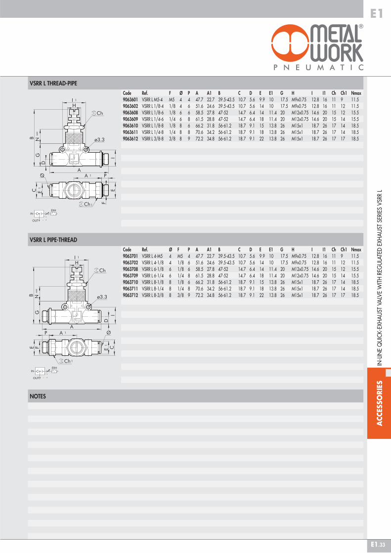
VSRR L THREAD-PIPE
VSRR L PIPE-THREAD
NOTES
IN-L
INE
QU
ICK
-EXH
AU
ST V
ALV
E W
ITH
REG
ULA
TED
EXH
AU
ST S
ERIE
S V
SRR
L
Code Ref. F Ø P A A1 B C D E E1 G H I I1 Ch Ch1 Nmax9063601 VSRR L M5-4 M5 4 4 47.7 22.7 39.5-43.5 10.7 5.6 9.9 10 17.5 M9x0.75 12.8 16 11 9 11.59063602 VSRR L 1/8-4 1/8 4 6 51.6 24.6 39.5-43.5 10.7 5.6 14 10 17.5 M9x0.75 12.8 16 11 12 11.59063608 VSRR L 1/8-6 1/8 6 6 58.5 27.8 47-52 14.7 6.4 14 11.4 20 M12x0.75 14.6 20 15 12 15.59063609 VSRR L 1/4-6 1/4 6 8 61.5 28.8 47-52 14.7 6.4 18 11.4 20 M12x0.75 14.6 20 15 14 15.59063610 VSRR L 1/8-8 1/8 8 6 66.2 31.8 56-61.2 18.7 9.1 15 13.8 26 M15x1 18.7 26 17 14 18.59063611 VSRR L 1/4-8 1/4 8 8 70.6 34.2 56-61.2 18.7 9.1 18 13.8 26 M15x1 18.7 26 17 14 18.59063612 VSRR L 3/8-8 3/8 8 9 72.2 34.8 56-61.2 18.7 9.1 22 13.8 26 M15x1 18.7 26 17 17 18.5
Code Ref. Ø F P A A1 B C D E E1 G H I I1 Ch Ch1 Nmax9063701 VSRR L 4-M5 4 M5 4 47.7 22.7 39.5-43.5 10.7 5.6 9.9 10 17.5 M9x0.75 12.8 16 11 9 11.59063702 VSRR L 4-1/8 4 1/8 6 51.6 24.6 39.5-43.5 10.7 5.6 14 10 17.5 M9x0.75 12.8 16 11 12 11.59063708 VSRR L 6-1/8 6 1/8 6 58.5 27.8 47-52 14.7 6.4 14 11.4 20 M12x0.75 14.6 20 15 12 15.59063709 VSRR L 6-1/4 6 1/4 8 61.5 28.8 47-52 14.7 6.4 18 11.4 20 M12x0.75 14.6 20 15 14 15.59063710 VSRR L 8-1/8 8 1/8 6 66.2 31.8 56-61.2 18.7 9.1 15 13.8 26 M15x1 18.7 26 17 14 18.59063711 VSRR L 8-1/4 8 1/4 8 70.6 34.2 56-61.2 18.7 9.1 18 13.8 26 M15x1 18.7 26 17 14 18.59063712 VSRR L 8-3/8 8 3/8 9 72.2 34.8 56-61.2 18.7 9.1 22 13.8 26 M15x1 18.7 26 17 17 18.5
ACC
ESSO
RIES
E1
E1.34
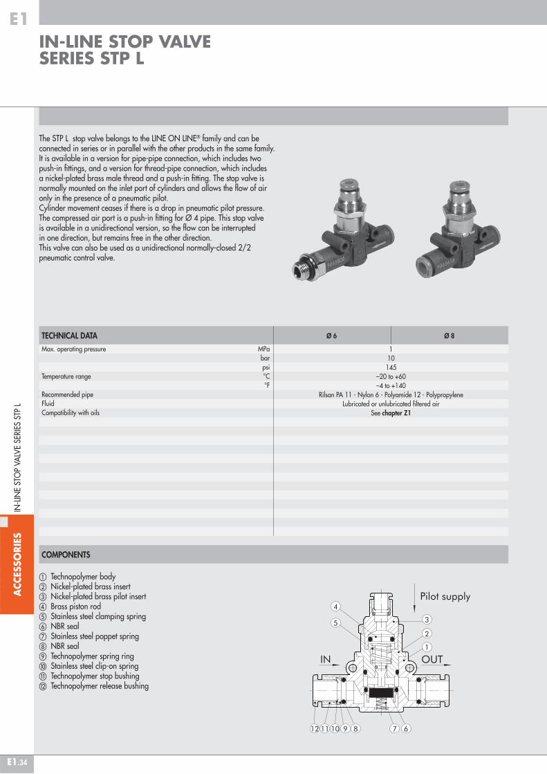
The STP L stop valve belongs to the LINE ON LINE® family and can be connected in series or in parallel with the other products in the same family.It is available in a version for pipe-pipe connection, which includes two push-in fittings, and a version for thread-pipe connection, which includes a nickel-plated brass male thread and a push-in fitting. The stop valve is normally mounted on the inlet port of cylinders and allows the flow of air only in the presence of a pneumatic pilot. Cylinder movement ceases if there is a drop in pneumatic pilot pressure. The compressed air port is a push-in fitting for Ø 4 pipe. This stop valve is available in a unidirectional version, so the flow can be interruptedin one direction, but remains free in the other direction. This valve can also be used as a unidirectional normally-closed 2/2 pneumatic control valve.
TECHNICAL DATAMax. operating pressure MPa bar psiTemperature range °C °FRecommended pipeFluidCompatibility with oils
Ø 6 Ø 8
110145
–20 to +60–4 to +140
Rilsan PA 11 - Nylon 6 - Polyamide 12 - PolypropyleneLubricated or unlubricated filtered air
See chapter Z1
COMPONENTS
� Technopolymer body� Nickel-plated brass insert� Nickel-plated brass pilot insert� Brass piston rod � Stainless steel clamping spring � NBR seal� Stainless steel poppet spring NBR seal Technopolymer spring ring� Stainless steel clip-on spring� Technopolymer stop bushing Technopolymer release bushing
IN-LINE STOP VALVE SERIES STP L
IN-L
INE
STO
P VA
LVE
SERI
ES S
TP L
#TAG_E1_00120

ACC
ESSO
RIES
E1
E1.35
ASSEMBLY OPTIONS
� � �
How to mount the STP L:• Fig. � With the male threaded port it is possible to mount the STP L straight onto the actuator or the control valve.• Fig. � Fixing to the plate with the special SQU L bracket.• Fig. � There are two robust rings on the plastic body for fixing the STP L straight onto the wall.• Fig. � The ring nut is screwed onto the threaded metal part of the STP L body for panel mounting.
�
MINIMUM PILOT PRESSURE
STP L Ø 6
Pressure [bar]
STP L Ø 8
Pressure [bar]
Pilo
t pre
ssur
e [b
ar]
Pilo
t pre
ssur
e [b
ar]
STP L Ø 6
Circuit pressure [bar]
STP L Ø 8
Circuit pressure [bar]
Flow
rat
e [N
l/m
in]
Flow
rat
e [N
l/m
in]
FLOW CHARTS
IN-L
INE
STO
P VA
LVE
SERI
ES S
TP L
ACC
ESSO
RIES
E1
E1.36
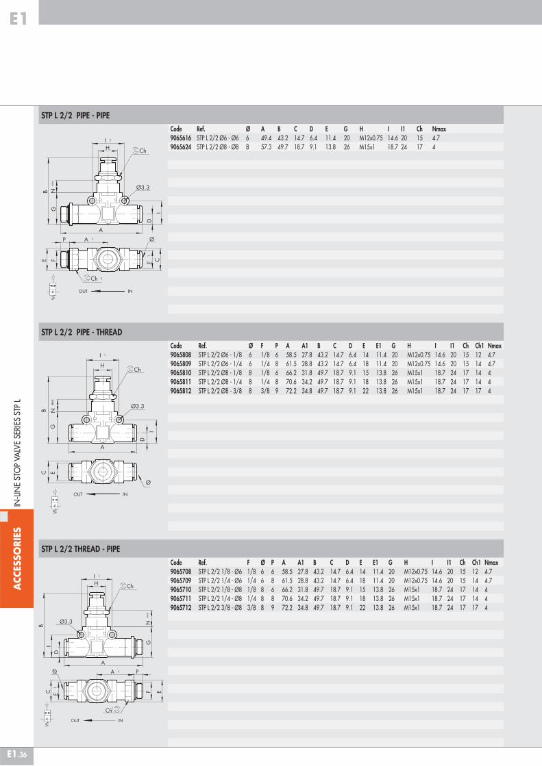
Code Ref. F Ø P A A1 B C D E E1 G H I I1 Ch Ch1 Nmax9065708 STP L 2/2 1/8 - Ø6 1/8 6 6 58.5 27.8 43.2 14.7 6.4 14 11.4 20 M12x0.75 14.6 20 15 12 4.79065709 STP L 2/2 1/4 - Ø6 1/4 6 8 61.5 28.8 43.2 14.7 6.4 18 11.4 20 M12x0.75 14.6 20 15 14 4.79065710 STP L 2/2 1/8 - Ø8 1/8 8 6 66.2 31.8 49.7 18.7 9.1 15 13.8 26 M15x1 18.7 24 17 14 49065711 STP L 2/2 1/4 - Ø8 1/4 8 8 70.6 34.2 49.7 18.7 9.1 18 13.8 26 M15x1 18.7 24 17 14 49065712 STP L 2/2 3/8 - Ø8 3/8 8 9 72.2 34.8 49.7 18.7 9.1 22 13.8 26 M15x1 18.7 24 17 17 4
STP L 2/2 PIPE - THREAD
STP L 2/2 THREAD - PIPE
Code Ref. Ø F P A A1 B C D E E1 G H I I1 Ch Ch1 Nmax9065808 STP L 2/2 Ø6 - 1/8 6 1/8 6 58.5 27.8 43.2 14.7 6.4 14 11.4 20 M12x0.75 14.6 20 15 12 4.79065809 STP L 2/2 Ø6 - 1/4 6 1/4 8 61.5 28.8 43.2 14.7 6.4 18 11.4 20 M12x0.75 14.6 20 15 14 4.79065810 STP L 2/2 Ø8 - 1/8 8 1/8 6 66.2 31.8 49.7 18.7 9.1 15 13.8 26 M15x1 18.7 24 17 14 49065811 STP L 2/2 Ø8 - 1/4 8 1/4 8 70.6 34.2 49.7 18.7 9.1 18 13.8 26 M15x1 18.7 24 17 14 49065812 STP L 2/2 Ø8 - 3/8 8 3/8 9 72.2 34.8 49.7 18.7 9.1 22 13.8 26 M15x1 18.7 24 17 17 4
IN-L
INE
STO
P VA
LVE
SERI
ES S
TP L
STP L 2/2 PIPE - PIPE
Code Ref. Ø A B C D E G H I I1 Ch Nmax9065616 STP L 2/2 Ø6 - Ø6 6 49.4 43.2 14.7 6.4 11.4 20 M12x0.75 14.6 20 15 4.79065624 STP L 2/2 Ø8 - Ø8 8 57.3 49.7 18.7 9.1 13.8 26 M15x1 18.7 24 17 4

ACC
ESSO
RIES
E1
E1.37
The VNR L check valve belongs to the LINE ON LINE® family, which means it can be connected to all the other components in series or in parallel.Available in the version for pipe-pipe connection with two push-in fittings, and in the version for thread-pipe connection with a brass nickel-plated male thread and a push-in fitting.It is still the only check valve with holes for wall mounting.
TECHNICAL DATA
ASSEMBLY OPTIONS
Operating pressure MPa bar psiTemperature range °C °FFlow rate at 6.3 bar ΔP 1 bar Nl/minRecommended pipeFluid
Ø 4 Ø 6 Ø 8
0.05 - 1.20.5 - 127.2 - 174
–20 to +60–4 to +140
80 320 480Rilsan PA11 - Nylon 6 - Polyamide 12 - Polypropylene
Lubricated or unlubricated filtered compressed air
� �
How to mount the VNR L:• Fig. � With the male threaded port it is possible to mount the VNR L straight onto the female thread.• Fig. � Fixing to the plate with the special SQU L bracket.• Fig. � There are two robust rings on the plastic body for fixing the VNR L straight onto the wall.
�
COMPONENTS
� Technopolymer body� Nickel-plated brass insert� NBR valve� Stainless steel valve compression spring� NBR gasket� Technopolymer spring ring� Stainless steel folding spring Technopolymer locking bushing Technopolymer release bushing
IN-LINE CHECK VALVE SERIES VNR L
IN-L
INE
CH
ECK
VA
LVE
SERI
ES V
NR
L
#TAG_E1_00130

ACC
ESSO
RIES
E1
E1.38
VNR L PIPE-PIPE
VNR L THREAD-PIPE
VNR L PIPE-THREAD
IN-L
INE
CH
ECK
VA
LVE
SERI
ES V
NR
L
Code Ref. Ø A B C D E I I19064001 VNR L 4-4 4 41.8 17.5 10.7 5.6 10 12.8 169064016 VNR L 6-6 6 49.4 20 14.7 6.4 11.4 14.6 209064024 VNR L 8-8 8 57.3 25.5 18.7 9.1 13.8 18.7 24
Code Ref. F Ø P A A1 B C E E1 I I1 Ch19064101 VNR L M5-4 M5 4 4 47.7 22.7 17.5 10.7 9.9 10 12.8 16 99064102 VNR L 1/8-4 1/8 4 6 50.6 24.6 17.5 10.7 14 10 12.8 16 129064108 VNR L 1/8-6 1/8 6 6 58.5 27.8 20 14.7 14 11.4 14.6 20 129064109 VNR L 1/4-6 1/4 6 8 61.5 28.8 20 14.7 18 11.4 14.6 20 149064110 VNR L 1/8-8 1/8 8 6 66.2 31.8 25.5 18.7 15 13.8 18.7 24 149064111 VNR L 1/4-8 1/4 8 8 70.6 34.2 25.5 18.7 18 13.8 18.7 24 149064112 VNR L 3/8-8 3/8 8 9 72.2 34.8 25.5 18.7 22 13.8 18.7 24 17
Code Ref. Ø F P A A1 B C E E1 I I1 Ch19064201 VNR L 4-M5 4 M5 4 47.7 22.7 17.5 10.7 9.9 10 12.8 16 99064202 VNR L 4-1/8 4 1/8 6 50.6 24.6 17.5 10.7 14 10 12.8 16 129064208 VNR L 6-1/8 6 1/8 6 58.5 27.8 20 14.7 14 11.4 14.6 20 129064209 VNR L 6-1/4 6 1/4 8 61.5 28.8 20 14.7 18 11.4 14.6 20 149064210 VNR L 8-1/8 8 1/8 6 66.2 31.8 25.5 18.7 15 13.8 18.7 24 149064211 VNR L 8-1/4 8 1/4 8 70.6 34.2 25.5 18.7 18 13.8 18.7 24 149064212 VNR L 8-3/8 8 3/8 9 72.2 34.8 25.5 18.7 22 13.8 18.7 24 17
ACC
ESSO
RIES
E1
E1.39
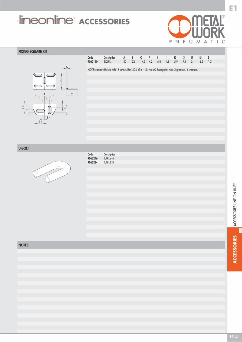
FIXING SQUARE KIT
U-BOLT
NOTES
Code Description A B C F I I1 I2 I3 I4 I5 S9062110 SQU L 30 22 14.5 4.2 6.8 4.8 5.9 9.1 2 6.5 1.2
NOTE: comes with two m3x16 screws (for L.O.L. Ø 6 - 8), two m3 hexagonal nuts, 2 groovers, 4 washers.
Code Description9062216 TUB L 6-69062224 TUB L 8-8
AC
CES
SORI
ES L
INE
ON
LIN
E®
ACCESSORIES
#TAG_E1_00140