e - Submission Guideline Mechanical, Electrical, Plumbing · 09/01/2012 · e - Submission...
62
BIM e - Submission Guideline Mechanical, Electrical, Plumbing While BCA tries to highlight the major points of submission requirements, BCA cannot take into account all the special cases in other regulatory agencies as well as the changing technology. Updated versions will continue to be issued to address and incorporate on-going feedback in an open, collaborative process. All readers of this provisional guide are encouraged to submit feedback to BCA CORENET. No part of these materials should be copied, reproduced or published in any form by any means whatsoever electronic or mechanical including photocopy or by way of any information storage or retrieval system nor should the material be disclosed to other parties without the express written authorization of Building and Construction Authority. Information and contents set forth in this document are subject to changes and will be released as updates in subsequent version. Building and Construction Authority 5 Maxwell Road #16-00 Tower Block MND Complex Singapore 069110 www.bca.gov.sg
Transcript of e - Submission Guideline Mechanical, Electrical, Plumbing · 09/01/2012 · e - Submission...

BIM e - Submission Guideline
Mechanical, Electrical, Plumbing
While BCA tries to highlight the major points of submission requirements, BCA cannot take into account all
the special cases in other regulatory agencies as well as the changing technology. Updated versions will
continue to be issued to address and incorporate on-going feedback in an open, collaborative process. All
readers of this provisional guide are encouraged to submit feedback to BCA CORENET.
No part of these materials should be copied, reproduced or published in any form by any means
whatsoever electronic or mechanical including photocopy or by way of any information storage or retrieval
system nor should the material be disclosed to other parties without the express written authorization of
Building and Construction Authority.
Information and contents set forth in this document are subject to changes and will be released as
updates in subsequent version.
Building and Construction Authority
5 Maxwell Road #16-00 Tower Block MND
Complex Singapore 069110
www.bca.gov.sg

Version Revision Date Summary of Changes Remarks
1.0 Oct 10 Released to Pilot Sites
2.0 Apr 11 Re-specification of BM project delivery to various regulatory agencies
Addition of requirements to the following agencies: IDA - TFCC CityGas PUB Water
Amendments on the requirements of the following agencies: FSSD NEA-CBPU / PUB-WRN
Released April 2011
3 Jul 11 Re-organized requirements of the City Gas agency
For Release
Copyright © 2010 Building and Construction Authority
For further comments or questions, please write to:
BCA Centre for Construction IT BIM Team
Building and Construction Authority
5 Maxwell Road
#16-00 Tower Block MND Complex
Singapore 069110

BIM Submission Guideline for Mechanical, Electrical & Plumbing Discipline
i
CONTENTS CONTENTS ................................................................................................................................. i
TABLES ..................................................................................................................................... ii
FIGURES .................................................................................................................................... ii
1. Introduction ............................................................................................. 1
1.1. Purpose of Document ................................................................................................ 1
1.2. Scope ......................................................................................................................... 1
2. General Requirements............................................................................ 2
2.1. Deliverable Format ..................................................................................................... 2
2.2. Model Scale ............................................................................................................... 3
2.3. Model Orientation and Site Configuration .................................................................. 3
2.4. Standard Naming of File and Drawing Views ............................................................ 4
2.5. Annotations and Dimensions ..................................................................................... 5
2.6. Last Saved Model or Last Saved View ...................................................................... 6
2.7. Model for Addition and Alteration Works/ Amendments ............................................ 7
Appendix A Specific Submission Requirements ........................................ 9
A-1 NEA-CBPU and PUB-WRN Submission Requirements ............................................ 9
1. General Requirements for all CBPU/ PUB-WRN Submissions .......................... 10
2. Development Control .......................................................................................... 10
3. Building Plan on Pollution Control ....................................................................... 13
4. Building Plan on Environmental Health ............................................................... 15
5. Detailed Plan on Sewerage Works (Proposed Sewer/ Sewer Diversion Works,
abandoned sewers and pumping mains/grouting of abandoned sewers and
pumping mains/Sewage treatment plant/holding tanks, etc) .............................. 17
6. Detailed Plan on Sanitary Works (for Sanitary Plumbing & Drainage System/
Sewer Connection) .............................................................................................. 19
7. Detailed Plan on Sewerage M&E Works ............................................................ 22
8. Detailed Plan on Drainage Works – Main Development Submission ................. 23
9. Detailed Plan on Drainage Works – Proposed Roadside Drain/ Culvert ............ 25
10. As-built Plan for TOP/CSC – Proposed Sewer/ Pumping Mains/ Sewer/
Pumping Main Diversion Works/abandoned sewers and pumping mains/grouting
of abandoned sewers and pumping mains/Sewage treatment plant/holding tanks,
etc ........................................................................................................................ 27
11. As-built Plan for TOP/CSC – Sanitary Works (Sanitary Plumbing & Drainage
System/ Sewer Connection)................................................................................ 29
12. As-built Plan for CSC – Proposed Roadside Drain/ Culvert ............................. 33
13. As-built Plan for CSC – Pumped Drainage System at Basement ..................... 35

BIM Submission Guideline for Mechanical, Electrical & Plumbing Discipline
ii
14. As-built Plan for CSC – Internal Drain with Deviations ..................................... 35
15. Certified Survey Plan for CSC – Development in the Vicinity of/ Affected by
Drainage Reserve ............................................................................................... 36
16. URA Approved Sub-division Plan for CSC – for Site Affected by Drainage
Reserve ............................................................................................................... 36
A-2 PUB-WTR Submission Requirements ..................................................................... 38
1. General Requirements for all PUBWTR Submissions ........................................ 38
A-3 FSSD Submission Requirements ............................................................................ 41
1. General Requirements for All FSSD Submissions .............................................. 41
A-4 IDA-TFCC Submission Requirements ..................................................................... 44
1. General Requirements for Submission of Plans to IDA ...................................... 44
A-5 CITYGAS Submission Requirements ...................................................................... 46
Appendix B Standard Certifications for M&E Works ................................ 48
B-1 NEA-CBPU / PUB-WRN: Qualified Person’s Endorsements .................................. 48
B-2 PUB Water: Qualified Person’s Endorsements ....................................................... 48
B-3 FSSD: Qualified Person’s Endorsements ................................................................ 49
B-4 IDA-TFCC: Qualified Person’s Endorsements ......................................................... 51
B-5 CITYGAS: Qualified Person’s Endorsements .......................................................... 51
Appendix C Step-by-Step Guide Preparing for BIM Submission ............. 52
C-1 Users of Autodesk Revit .......................................................................................... 52
ACKNOWLEDGEMENTS ....................................................................................................... 55
GLOSSARY OF ACRONYMS USED ..................................................................................... 56
OBJECT LIBRARIES .............................................................................................................. 57
NOTES .................................................................................................................................... 58
TABLES Table 1 Accepted file format in BIM submission for regulatory approval ...................................2
Table 2 Naming convention for each 3D model or BIM file submitted .......................................4
Table 3 Naming convention for each drawing view ...................................................................5
Table 4 Colours used for A&A project ........................................................................................7
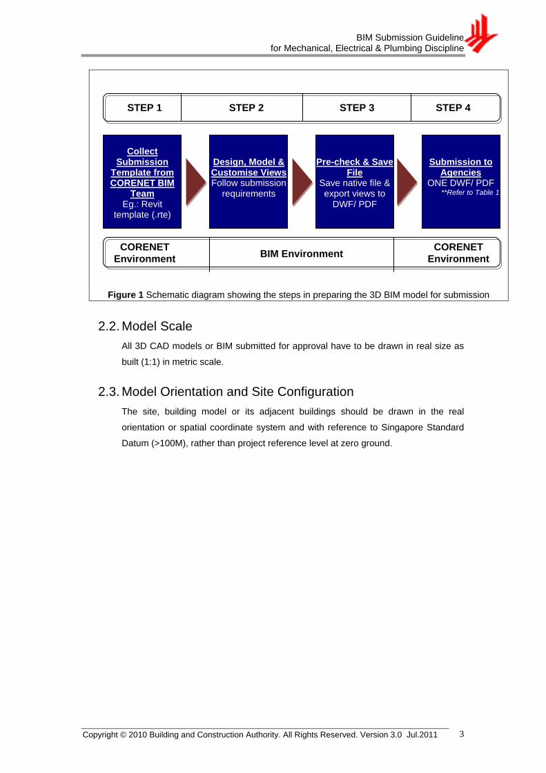
FIGURES Figure 1 Schematic diagram showing the steps in preparing the 3D BIM model for submission
.....................................................................................................................................3
Figure 2 Sample of new erection project with name of plan indicated at the bottom ................6
Figure 3 Sample of A&A project / project for re-submission (plan and 3D views) .....................7
Figure 4 Sample of project for re-submission (plan view for storey with no amendments) ...... 8

BIM Submission Guideline for Mechanical, Electrical & Plumbing Discipline
Copyright © 2010 Building and Construction Authority. All Rights Reserved. Version 3.0 Jul.2011 1
1. Introduction
1.1. Purpose of Document
The objective of this Document is to assist qualified persons (QPs) in developing
BIM models to meet new requirements of Building Information Model (BIM)
submission. It describes the requirements and guidance for creating BIM with
specific object types, associated properties and presentation format to the following
regulatory agencies for visual processing:
a. National Environment Agency (NEA), Central Building Plan Unit
b. Public Utility Board (PUB), Water Reclamation (Network) Department
c. Public Utility Board (PUB), Water Supply Network Department
d. Fire Safety and Shelter Department (FSSD)
e. Infocomm Development Authority (IDA)
f. CityGas Pte Ltd
1.2. Scope
This submission guideline contains a list of requirements written in a concise form to
guide QPs in preparing BIM submission to the above mentioned regulatory
agencies. It is by no means an exhaustive list of requirements of the building works
which must be complied with when making a building plan or planning submission.
The items in this Standard Guideline may also be amended or revoked when new
written laws come into force. For more information or enquiries on the specific
submission requirements, please consult the appropriate regulatory agency above.
CAD vendors and retailers have developed their own application dependent user
manuals. These user manuals should be read carefully as this Document cannot
take into account all the special features of individual BIM application. For any
submission requirements mentioned in the Appendices that require customisations
to a certain extent, QPs are also advised to make reference to the training materials
distributed or to consult the respective software vendor for any enquiries on the
application.
Note: The respective regulatory agency reserves the right to reject and request for necessary correction of any required deliverables or formats that do not meet the requirements.

BIM Submission Guideline for Mechanical, Electrical & Plumbing Discipline
Copyright © 2010 Building and Construction Authority. All Rights Reserved. Version 3.0 Jul.2011 2
2. General Requirements
2.1. Deliverable Format
QPs are required to submit BIM saved in the file format, as summarized in Table 1,
upon submission to each of the above mentioned regulatory agencies.
Table 1 Accepted file format in BIM submission for regulatory approval
Regulatory Agencies Accepted File Format for BIM
Submission Remarks
BIM submissions to other regulatory agencies:
a. CBPU; b. PUB-WRN; c. PUB-WTR; d. FSSD; e. IDA-TFCC; and f. CityGas
a. A single light-weighted file format, as published from the similar BIM native file:
i. DWF (.dwf); or ii. PDF (.pdf)
The respective regulatory agency reserves the right to request BIM native file for verification, ONLY if necessary.
All drawing views below should be compiled into a single DWF/PDF file.
Refer to Appendix C for detailed steps in publishing to DWF/PDF.
a. Plans, elevations, sections, layout views or sheets (refer to Appendix A for specific
requirements from each regulatory agency), with appropriate title block and QP’s
stamp;
b. Schematic Diagram is required for submission to all agencies involved
c. Legend is required for submission to all agencies involved
d. 3D model views:
Complete 3D DWF model showing the complete services
Part 3D model (services + archi model, if any) by shafts/ important part cross
sections (Refer to Appendix A)
Take note of the naming convention – if part section, include grid numbers
(Refer to Section 2.4)
Note: QPs are adviced to test the published DWF/PDF file prior to submission to respective agencies. If the published file failed or consumed time to open due to file size or volume of MEP elements involved, QPs are suggested to have separate DWF/PDF file for sheets and 3D views.
Note: All BIM e-submission through CORENET e-Submission System is limited to not more than 100MB per file per submission. If the file size is larger than 100MB, QPs are requested to deliver in CD-ROM to the respective agency.
BIM Submission Guideline for Mechanical, Electrical & Plumbing Discipline
Copyright © 2010 Building and Construction Authority. All Rights Reserved. Version 3.0 Jul.2011 3
ss
Figure 1 Schematic diagram showing the steps in preparing the 3D BIM model for submission
2.2. Model Scale
All 3D CAD models or BIM submitted for approval have to be drawn in real size as
built (1:1) in metric scale.
2.3. Model Orientation and Site Configuration
The site, building model or its adjacent buildings should be drawn in the real
orientation or spatial coordinate system and with reference to Singapore Standard
Datum (>100M), rather than project reference level at zero ground.
Collect
Submission Template from CORENET BIM
Team Eg.: Revit
template (.rte)
Design, Model & Customise Views Follow submission
requirements
Submission to Agencies
ONE DWF/ PDF **Refer to Table 1
Pre-check & Save File
Save native file & export views to
DWF/ PDF
CORENET
Environment BIM Environment
CORENET
Environment
STEP 1 STEP 2 STEP 3 STEP 4

BIM Submission Guideline for Mechanical, Electrical & Plumbing Discipline
Copyright © 2010 Building and Construction Authority. All Rights Reserved. Version 3.0 Jul.2011 4
2.4. Standard Naming of File and Drawing Views
File naming convention below (as modified from SS CP83 Part 3) should be used
for all project files submitted:
Sample:
Project ID Author Zone Version User-defined
M L P 1 _ M - 0 1 _ A -
Table 2: Naming convention for each 3D model or BIM file submitted
Name of Field Indicators Description
Project Identification User defined field for the project
Author A- Architect
C- Civil engineer
E- Electrical engineer
L- Land surveyor
M- Mechanical engineer
N- Equipment supplier
S- Structural engineer
T- Telecommunication/ Signal engineer
V- Other disciplines
X- Contractor
Zone (or Block) NN where, N: zone or block number e.g.: 01 for Block 1 A1 for Zone A1
-- For all blocks
Version (Revision/ Submission)
A- 1st submission
B- 2nd
submission
C- 3rd
submission
User-defined (Optional) User defined code for in-house applications (optional field)
Within each DWF/PDF submitted to the regulatory agencies, all its related drawing
views (plans, elevations, sections and 3D views) and layouts (contain only data
information such as qualified person’s declarations and schedules) should follow the
naming convention below:
Sample:
Agency Type of View View Name
F S S D - _ F P _ 1ST S T O R E Y
Note: Follow the submission template provided and it should give you a guide to begin.

BIM Submission Guideline for Mechanical, Electrical & Plumbing Discipline
Copyright © 2010 Building and Construction Authority. All Rights Reserved. Version 3.0 Jul.2011 5
Table 3 Naming convention for each drawing view
Name of Field Indicators Description
Agency CBPU Central Building Plan Unit
PUB-WRN Public Utility Board, Water Reclamation (Network)
PUB-WTR Public Utility Board, Water Supply Network
FSSD Fire Safety and Shelter Department
IDA-TFCC Infocomm Development Authority, Telecommunication Facility Coordination Committee
CITYGAS CityGas Pte Ltd
Type of View SP Site Plan
FP Floor Plan
FE Elevation
FX Section
DT Details
3D 3D View
LG Legend
DG Schematic Diagram
View Name 1ST
STOREY; or 2
ND STOREY; or
3RD
STOREY; or N
TH STOREY; or
LOWER ROOF; or ROOF
where, N: Storey’s number
MEZZANINE N where, N: Mezzanine’s number
BASEMENT N where, N: Basement’s number
ELEVATION N or N ELEVATION where, N: Directions (e.g.: East, West, North, South; or 1, 2, 3, 4)
SECTION N where, N: Section’s number
SUMMARY OF GFA; or SUMMARY OF INCENTIVE GFA; or SUMMARY OF X
Where, X: Schedule’s Name
2.5. Annotations and Dimensions
Except for 3D model view, all other submitted views such as plans, schematic
diagrams, elevations and sections should be indicated clearly with the necessary
annotations, dimensions, scalebar and north point, as specified by the respective
regulatory agency in Appendix A. Within each of the model view, QPs are also
required to include the related name of view, as shown in Figure 2.

BIM Submission Guideline for Mechanical, Electrical & Plumbing Discipline
Copyright © 2010 Building and Construction Authority. All Rights Reserved. Version 3.0 Jul.2011 6
Figure 2 Sample of new erection project with name of plan indicated at the bottom
2.6. Last Saved Model or Last Saved View
Checking and approval from the regulatory agencies is based on the ―Last Saved
Model‖, together with the ―Last Saved View‖ of site plans, floor plans, elevations and
sections submitted. Therefore, QPs are to ensure that the following items are
checked upon submission:
a. Maximum extent is saved for each drawing view;
b. No hidden objects or annotations;
c. Any link (3D model or BIM saved in other file) that is considered part of
the submission is bind as a single integrated BIM;
d. All other external references, irrelevant drawing layers, objects,
annotations, draft work and construction lines, which are not part of the
constructed building elements, are to be removed or purged upon
submission; and
e. No propriety fonts are used for annotations and all the fonts should be
legible; and
f. All objects and annotation in each phase were displayed in the last saved
view.

BIM Submission Guideline for Mechanical, Electrical & Plumbing Discipline
Copyright © 2010 Building and Construction Authority. All Rights Reserved. Version 3.0 Jul.2011 7
2.7. Model for Addition and Alteration Works/ Amendments
The same BIM model (with changes incorporated to comply with the requirements)
should be used in resubmission (i.e. no shifting of spatial coordinate system in the
re-submitted model). The revised submission should be indicated clearly in the
name of BIM file submitted, following the format at Section 2.4.
For any plan of alteration or addition to an existing building, or, re-submission for
regulatory approval, all the building objects or elements should be demarcated
clearly by colours in Table 4 (in accordance with SS CP83 Part 5):
Table 4 Colours used for A&A project
Colour Usage
Magenta Proposed elements
Cyan Existing elements
Yellow Deleted elements
Any building works which are to be deleted, removed or demolished must be shown
in dotted lines on the plans and presented in a manner that can be easily identified
or distinguished, as shown in Figure 3.
Figure 3 Sample of A&A project / project for re-submission (plan and 3D views)

BIM Submission Guideline for Mechanical, Electrical & Plumbing Discipline
Copyright © 2010 Building and Construction Authority. All Rights Reserved. Version 3.0 Jul.2011 8
QPs should include a complete set of all related model views (plans, elevations,
sections and 3D views) in every submission, including the re-submission of
amendments. For any model view which contains NO amendments, a box indicating
that this is ―For Reference ONLY‖ shall be placed on the top right corner of the
model view, and all its building objects or elements shall be demarcated with CYAN
colour, as shown in Figure 4.
Figure 4 Sample of project for re-submission (plan view for storey with no amendments)

BIM Submission Guideline for Mechanical, Electrical & Plumbing Discipline
Copyright © 2010 Building and Construction Authority. All Rights Reserved. Version 3.0 Jul.2011 9
Appendix A Specific Submission Requirements
A-1 NEA-CBPU and PUB-WRN Submission Requirements
The individual section below covers the specific presentation requirements necessary
for each of the drawing views submitted to CBPU and PUB at the various stages
below:
1. Development Control;
2. Building Plan on Pollution Control;
3. Building Plan on Environmental Health;
4. Detailed Plan on Sewerage Works (Proposed Sewer/ Sewer Diversion
Works/abandoned sewers and pumping mains/grouting of abandoned
sewers and pumping mains/Sewage treatment plant/holding tanks, etc);
5. Detailed Plan on Sanitary Works (for Sanitary Plumbing & Drainage
System/ Sewer Connection);
6. Detailed Plan on Sewerage M&E Works;
7. Detailed Plan on Drainage Works – Main Development Submission;
8. Detailed Plan on Drainage Works – Proposed Roadside Drain/ Culvert;
9. As-built Plan for TOP/CSC – Proposed Sewer/ Pumping Mains/ Sewer/
Pumping Main Diversion Works; abandoned sewers and pumping
mains/grouted abandoned sewers and pumping mains/Sewage Treatment
Plants/Holding Tank, etc.;
10. As-built Plan for TOP/CSC – Sanitary Works (Sanitary Plumbing &
Drainage System/ Sewer Connection);
11. As-built Plan for CSC – Proposed Roadside Drain/ Culvert;
12. As-built Plan for CSC – Pumped Drainage System at Basement;
13. As-built Plan for CSC – Internal Drain with Deviations;
14. Certified Survey Plan for CSC – Development in the vicinity of/ affected by
Drainage Reserve; and
15. URA Approved Sub-division Plan for CSC – for Site affected by Drainage
Reserve.
Please note that symbols, layers, drafting conventions, line types and colours should
follow the Singapore Standard CP83: Code of Practice for Construction computer
aided design (CAD).

BIM Submission Guideline for Mechanical, Electrical & Plumbing Discipline
Copyright © 2010 Building and Construction Authority. All Rights Reserved. Version 3.0 Jul.2011 10
1. General Requirements for all CBPU/ PUB-WRN Submissions
QPs are to take note of the requirements below for all CBPU/ PUB-WRN submission:
a. Site Plan: Include the connection to main pipe
b. Drawing scale of Site Plan:Use either 1:500, 1:1000 (do not use odd scale)
c. Key plan/Location plan to show surrounding site and location
2. Development Control
2.1. Site Plan View
In specific, all key plan, location plan and site plan of development control shall
show the following:
2.1.1. Key Plan
a. Boundary of development site shall be edged RED; and
b. Outline of neighbouring development plots or buildings within 1km
radius shall be shown.
2.1.2. Location Plan
a. Boundary of development site shall be edged RED; and
b. Outline of neighbouring development plots or buildings and MRT tracks,
within a 100m radius shall be shown.
2.1.3. Site Plan
Site plan shall show the following:
a. Layout of the site with boundary lines verged in RED. Road name , town
subdivision, mukim and lot numbers and areas (m2)
b. Outline of buildings or structure;
c. Building setback from MRT track;
d. Existing sewers (including DTSS tunnels), pumping mains and sewerage
facilities, including their sizes, as reflected in Sewerage Interpretation
Plans, within 25m (for sewers) or 36m (for DTSS tunnels) of
development boundary; Outline of the Sewer Protection zone (25m from
sewers or 36m from DTSS tunnels).
e. Outline of sewer setback distance from sewers or pumping mains and
clear horizontal distance between structures or buildings and the sewers;
f. Bin centre location and vehicular access;
g. Existing Drainage reserves line with dimensions, entrance culverts or
roadside drains;

BIM Submission Guideline for Mechanical, Electrical & Plumbing Discipline
Copyright © 2010 Building and Construction Authority. All Rights Reserved. Version 3.0 Jul.2011 11
h. Proposed, proposed abandon sewers and sewer connection line or
pumping mains or drains, sewer or pumping main diversion work
(including their sizes), holding tank or sewage treatment plant or sewage
pump sump;
i. Existing or proposed internal drains serving the development site from
summit points to its outlet connection to the existing or proposed
roadside drain or outlet drain; and
j. Road reserves line with dimensions, road levels or ground levels
including the existing road levels or ground levels at the outlet discharge
point of internal drains.
2.2. Floor Plan View
In specific, all basement, 1st storey and higher storey plan of development control
shall show the proposed platform levels for all areas, room’s tag and the following:
2.2.1. Basement Plan
a. For industrial development, use of floor space for industrial processes or
activities;
b. Provision for pollution control equipment;
c. Toilets/sanitary facilities, refuse chute chambers, car washing bays,
garage gully and oil interceptor;
d. Food shops and grease traps;
e. Provision for pump sewerage system, if used water is generated;
f. All entrance or openings to the basement, platform levels, cut-off drains,
crest levels, threshold levels and drainage pump system; and all
adjacent road levels (both at the front and the back of site) or ground
levels.
g. Areas open to sky to be served by pumped drainage system; and
h. Bin centre and vehicular access to the bin centre.
2.2.2. First Storey Plan
a. For industrial development, use of floor space for industrial processes or
activities;
b. Provision for pollution control equipment;
c. Bin centre and vehicular access to the bin centre;
d. Location of refuse chute chambers;
e. Existing, proposed and proposed abandon sewers, pumping mains,
sewer connection, including all their sizes, manholes, discharge

BIM Submission Guideline for Mechanical, Electrical & Plumbing Discipline
Copyright © 2010 Building and Construction Authority. All Rights Reserved. Version 3.0 Jul.2011 12
chambers, their top and invert levels, and their setback from buildings or
structures;
f. Sewer and Manhole ID for existing or proposed abandon sewer /
pumping main/ manhole
g. Adjacent lots and existing sewer/sanitary drain lines from adjacent lots,
h. Overhanging structures or roof eaves above existing or proposed sewer
or pumping main;
i. The last inspection chamber, pipe size,the top and invert of the last IC
and connecting manhole;
j. Reinforced concrete trench for sewer that do not meet building setback
requirement;
k. Drainage reserve and its alignment and width;
l. Common drains and its alignment and flow of existing common drain
within the development site, layout of internal drainage system and
discharge point to the public drains and the drain size;
m. Proposed or existing platform level, adjacent road/ground levels at the
outlet discharge points of internal drains;
n. Road reserves line with dimensions;
o. Link to MRT station and /or existing building link to MRT station, if any;
p. Proposed ramp and boundary fence or walls.
2.2.3. Second Storey to Highest Storey Plan (for industrial
buildings only)
a. For industrial development, use of floor space for industrial processes or
activities; and
b. Provision for pollution control equipment.
2.3. Roof Plan View
In specific, the roof plan of development control shall show the following:
a. For industrial buildings, location of flue gas stacks and chimneys;
b. Provision for pollution control equipment;
c. Private roof terraces, gardens, common areas, common staircases;
d. Refuse chute, refuse chute ventilation openings, maintenance access to
the refuse chute; and
e. Roof gutter or scupper drains (if any), parapet walls and railings.
2.4. Elevation View
In specific, the elevation view of development control shall show the following:
a. For industrial buildings, location of flue gas stacks and chimneys;
b. Provision for pollution control equipment;
c. Building height;

BIM Submission Guideline for Mechanical, Electrical & Plumbing Discipline
Copyright © 2010 Building and Construction Authority. All Rights Reserved. Version 3.0 Jul.2011 13
d. Sewer setback from building or structures; Clear horizontal and vertical
distances between the building or structure and the sewers or pumping
mains
e. Location of reinforced concrete trench;
f. Refuse chute ventilation openings, roof gutter or scupper drains (if any),
parapet walls, railings;
g. Bin centre and its height;
h. Drainage reserve, common drains, roadside or external drains, existing
and proposed boundary fence or walls; and
i. Structures closer than 2.0m from the edge of the Drainage Reserve.
3. Building Plan on Pollution Control
3.1. Site Plan View
In specific, all key plan, location plan or site plan of pollution control shall show the
following:
3.1.1. Key Plan
a. Boundary of development site shall be edged RED; and
b. Outline of neighbouring development plots or buildings within 1km
radius shall be shown.
3.1.2. Location Plan or Site Plan
a. Boundary of development site shall be edged RED; and
b. Outline of neighbouring development plots or buildings and MRT tracks,
within a 100m radius shall be shown.
3.2. Floor Plan View
In specific, all basement, 1st storey and higher storey plan of pollution shall show
the following:
3.2.1. Basement Plan
a. All details or processes inside the basement of the building;
b. Trade effluent drainage or piping system to collect and convey trade
effluent generated;
c. Location of trade effluent treatment plant;
d. Location of trade effluent sampling sump or system and the
connection to the internal sanitary drainage system;

BIM Submission Guideline for Mechanical, Electrical & Plumbing Discipline
Copyright © 2010 Building and Construction Authority. All Rights Reserved. Version 3.0 Jul.2011 14
e. Open process areas which may cause contamination to rain water and
system to collect contaminated rain water and system of treatment
before discharge to open drain;
f. Types and locations of fuel burning equipment;
g. Locations of air pollution control equipment;
h. Containment facility for storage tanks;
i. Locations of toxic industrial water treatment and disposal facilities;
j. Containment facilities for generator; and
k. Car washing bays, garage gully or oil interceptor.
3.2.2. First Storey Plan
a. All details or processes inside the first storey of the building;
b. Trade effluent drainage or piping system to collect and convey trade
effluent generated;
c. Location of trade effluent treatment plant;
d. Location of trade effluent sampling sump or system and the
connection to the internal sanitary drainage system;
e. Location of Last Inspection Chamber (includes pH monitoring and
discharge control system);
f. Open process areas which may cause contamination to rain water and
system to collect contaminated rain water and system of treatment
before discharge to open drain;
g. Types and locations of fuel burning equipment;
h. Locations of air pollution control equipment;
i. Containment facility for storage tanks;
j. Locations of toxic industrial water treatment and disposal facilities;
k. Containment facilities for generator; and
l. Air intake or exhaust points for mechanical ventilation system.
3.2.3. Second Storey to Highest Storey Plan
a. All processes or activities inside the second to highest storey of the
building;
b. Trade effluent drainage or piping system to collect and convey trade
effluent generated;
c. Location of trade effluent treatment plant;
d. Location of trade effluent sampling sump or system and the
connection to the internal sanitary drainage system;
e. Open process areas which may cause contamination to rain water and
system to collect contaminated rain water and system of treatment
before discharge to open drain;
f. Types and locations of fuel burning equipment;

BIM Submission Guideline for Mechanical, Electrical & Plumbing Discipline
Copyright © 2010 Building and Construction Authority. All Rights Reserved. Version 3.0 Jul.2011 15
g. Locations of air pollution control equipment;
h. Containment facility for storage tanks;
i. Locations of toxic industrial water treatment and disposal facilities; and
j. Air intake or exhaust points for mechanical ventilation system.
3.3. Roof Plan View
In specific, the roof plan of pollution control shall show the following:
a. Location of chimneys for the dispersion of flue gases;
b. Types and locations of fuel burning equipment;
c. Stacks for the dispersion of exhaust gases;
d. Cooling towers location and its overflow or drain-off point; and
e. Locations of air pollution control equipment.
3.4. Elevation View
In specific, the elevation of pollution control shall show the following:
a. Flue gas stacks and chimneys;
b. Types and locations of fuel burning equipment;
c. Building height;
d. Air pollution control equipment; and
e. Trade effluent treatment plant and toxic industrial water treatment and
disposal facilities.
4. Building Plan on Environmental Health
4.1. Site Plan View
In specific, all key plan, location plan and site plan of environmental health shall
show the following:
4.1.1. Key Plan
a. Boundary of development site shall be edged RED; and
b. Outline of neighbouring development plots or buildings within 1km
radius shall be shown.
4.1.2. Location Plan
a. Boundary of development site shall be edged RED; and
b. Outline of neighbouring development plots or buildings and MRT tracks,
within a 100m radius shall be shown.
4.1.3. Site Plan

BIM Submission Guideline for Mechanical, Electrical & Plumbing Discipline
Copyright © 2010 Building and Construction Authority. All Rights Reserved. Version 3.0 Jul.2011 16
Layout of the site with boundary lines verged in RED.
a. Neighbouring buildings;
b. Neighbouring clean and light industrial buildings (if any)
within 50m setback distance;
c. Overhead MRT within 35m setback distance from building or
structure; and
d. Bin centre and access, swimming pool and
restaurant/foodshops.
4.2. Floor Plan View
In specific, the basement, 1st storey and higher storey floor plan of environmental
health shall show the following:
4.2.1. Basement Plan
a. Refuse chute chambers and sanitary facilities or toilets; and
b. Food shops.
4.2.2. First Storey Plan
a. MRT setback lines and distance;
b. Bin centre and access;
c. Swimming pool, open spa or jacuzzi;
d. Refuse chute chambers and sanitary facilities or toilets;
e. Food shop and its kitchen or food preparation area, outdoor
refreshment area (if any) and washing area, sanitary pipes, drip tray,
double floor slab, hood and flue system and grease trap; and
f. Common drain.
4.2.3. Second Storey to Highest Storey Plan
a. Swimming pool and restaurant;
b. Refuse chute chambers and sanitary facilities or toilets; and
c. Food shop and its kitchen or food preparation area and washing area,
overhead sanitary pipes in food shop kitchens, drip tray, double floor
slab, hood and flue system.
4.3. Roof Plan View
In specific, the roof plan of environmental health shall show the following:
a. Location and ventilation openings for refuse chutes, common areas,
maintenance access to refuse chutes;
b. Roof gutter or scupper drains (if any), parapet walls or railing, permanent
and safe access to the roof gutters or roof scupper drains; and

BIM Submission Guideline for Mechanical, Electrical & Plumbing Discipline
Copyright © 2010 Building and Construction Authority. All Rights Reserved. Version 3.0 Jul.2011 17
c. Kitchen exhausts for foodshops.
4.4. Elevation View
In specific, the elevation view of environmental health shall show the following:
a. Refuse chutes and their ventilation openings, roof gutters or scupper
drains (if any), parapet walls, railings;
b. Building height;
c. Bin centre; and
d. Proposed boundary fence or walls and common drain.
5. Detailed Plan on Sewerage Works (Proposed Sewer/ Sewer
Diversion Works, abandoned sewers and pumping
mains/grouting of abandoned sewers and pumping
mains/Sewage treatment plant/holding tanks, etc)
5.1. Site Plan View
In specific, all key plan and site plan of proposed sewer or sewer diversion works
shall show the following:
5.1.1. Key Plan
a. Boundary of development site shall be edged RED; and
b. Outline of neighbouring development plots or buildings within 1km
radius shall be shown.
5.1.2. Site Plan
Layout of the site with boundary lines verged in RED and outline of
building and structure.
a. Proposed or existing or proposed abandon sewer or pumping
main or diversion and their setback distance from building or
structures or Drainage Reserve or neighbouring lot;
b. Reinforced concrete trench with removable slabs (annotated
on the plan) for existing or proposed sewer under building or
structures or with insufficient setback from building or
structures;
c. Pipe sizes, invert and top levels of all manholes including the
connecting manhole(s); and

BIM Submission Guideline for Mechanical, Electrical & Plumbing Discipline
Copyright © 2010 Building and Construction Authority. All Rights Reserved. Version 3.0 Jul.2011 18
d. Provision of or existing pump sump or holding tank or
sewage treatment plant.
5.2. First Storey Floor Plan View
In specific, the 1st storey floor plan of proposed sewer or sewer diversion works
shall show the outlines of building or structure and the following:
a. Proposed or existing or proposed abandon sewer or pumping main or
diversion, and their setback distance from building or structures or
Drainage Reserve or adjacent lot;
b. Reinforced concrete trench with removable slabs (annotated on the plan
with width and length dimension) for existing or proposed sewer under
building or structures or with insufficient setback from building or
structures;
c. Pipe sizes, gradients, materials, invert and top levels of all the manholes
including the connecting manhole(s);
d. Provision of pump sump or holding tank or sewage treatment plant; and
e. Proposed ramp, boundary fence or walls.
5.3. Elevation View
In specific, the elevation view of sewer or sewer diversion works shall show the
following:
a. Headroom for overhanging structures or roof eaves above existing or
proposed sewer or pumping main;
b. Pipe size and invert levels of the existing or proposed sewer or pumping
mains and their setback distance from building or structures;
c. Reinforced concrete trench with removable slabs (annotated on the plan
with width and depth dimension) for existing or proposed sewer under
building or structures or with insufficient setback from building or
structures;
d. Pipe sizes, invert and top levels of all the manholes including the
connecting manhole(s);
e. Building height;
f. Proposed boundary fence or walls; and
g. Pump sump or holding tank or sewage treatment plant.
5.4. Longitudinal Section View
In specific, the section view of sewer or sewer diversion works shall show the
following:
BIM Submission Guideline for Mechanical, Electrical & Plumbing Discipline
Copyright © 2010 Building and Construction Authority. All Rights Reserved. Version 3.0 Jul.2011 19
a. All existing or proposed manholes and sewers or pumping mains and its
materials, pipe sizes, distance, gradient and invert or top levels of
manhole with tumbling bay or backdrop connections (if any);
b. Method of laying and pipe haunching/bedding details;
c. Horizontal and vertical clearance distances of underground services or
structures from sewers or pumping mains, and
d. Headroom clearance of overhanging or overhead structures and their
horizontal clearance distance from sewers or pumping mains.
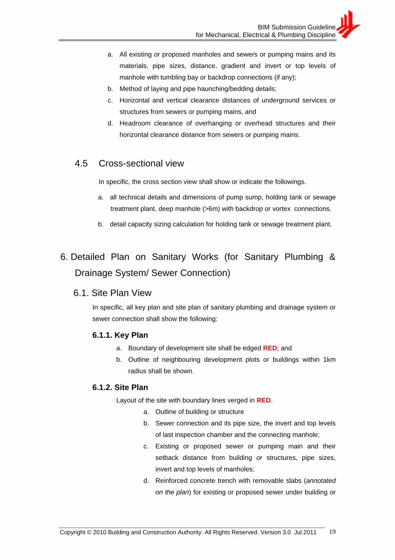
4.5 Cross-sectional view
In specific, the cross section view shall show or indicate the followings.
a. all technical details and dimensions of pump sump, holding tank or sewage
treatment plant, deep manhole (>6m) with backdrop or vortex connections.
b. detail capacity sizing calculation for holding tank or sewage treatment plant.
6. Detailed Plan on Sanitary Works (for Sanitary Plumbing &
Drainage System/ Sewer Connection)
6.1. Site Plan View
In specific, all key plan and site plan of sanitary plumbing and drainage system or
sewer connection shall show the following:
6.1.1. Key Plan
a. Boundary of development site shall be edged RED; and
b. Outline of neighbouring development plots or buildings within 1km
radius shall be shown.
6.1.2. Site Plan
Layout of the site with boundary lines verged in RED.
a. Outline of building or structure
b. Sewer connection and its pipe size, the invert and top levels
of last inspection chamber and the connecting manhole;
c. Existing or proposed sewer or pumping main and their
setback distance from building or structures, pipe sizes,
invert and top levels of manholes;
d. Reinforced concrete trench with removable slabs (annotated
on the plan) for existing or proposed sewer under building or

BIM Submission Guideline for Mechanical, Electrical & Plumbing Discipline
Copyright © 2010 Building and Construction Authority. All Rights Reserved. Version 3.0 Jul.2011 20
structures or with insufficient setback from building or
structures; and
e. Provision of or existing pump sump or holding tank or
sewage treatment plant.
6.2. Floor Plan View
In specific, the basement, 1st strorey and higher storey floor plan of sanitary
plumbing and drainage system or sewer connection shall show the following:
6.2.1. Basement Plan
a. All sanitary appliances or fittings and internal sanitary plumbing and
drainage system connected to the 1st storey inspection chambers or
the sewerage system;
b. Pipe sizes, gradients, materials, invert and top levels of the
sumps/chambers and inspection chambers;
c. Declaration of all pipe sizes and materials used for sanitary appliances
(eg. discharge pipe, urinal pipe, vent pipe, discharge stack, etc);
d. Provision of Sewerage pumping system;
e. Eating establishments/food shops and its kitchen or food preparation
areas and grease trap or sewage divertor, if any.
f. Potable water tank,
g. Overhead sanitary pipes in food shops’ kitchens or potable water tank;
h. Toilets/sanitary facilities, refuse chutes, and washing areas; and
i. Platform levels
6.2.2. First Storey Plan
a. All sanitary appliances or fittings or soil and vent stack(s) and their
connection to inspection chambers;
b. Internal sanitary drainage system and its connection to existing or
proposed sewer or manhole;
c. Pipe sizes, gradients, materials, invert and top levels of the
sumps/chambers and inspection chambers;
d. Declaration of all pipe sizes and materials used for sanitary appliances
(eg. discharge pipe, urinal pipe, vent pipe, discharge stack, etc);
e. Double floor slab (including access opening) for sanitary pipes sited
over bedroom, living room, dining room and kitchen area;
f. Reinforced concrete trench with removable slabs (annotated on the
plan with width and length dimension) for existing or proposed sewer
under building or structures or with insufficient setback from building or
structures;

BIM Submission Guideline for Mechanical, Electrical & Plumbing Discipline
Copyright © 2010 Building and Construction Authority. All Rights Reserved. Version 3.0 Jul.2011 21
g. Existing & proposed sewer or pumping main and their sizes, setback
from building or structure;
h. Invert and top levels of all the manholes including the connecting
manhole(s);
i. Adjacent lot and existing sewer/sanitary drainlines from adjacent lots,
j. Provision of pump sump or holding tank or sewage treatment plant.
k. Eating establishments/food shops and its kitchen or food preparation
areas and grease trap or sewage divertor, if any.
l. Potable water tank, and
m. Overhead sanitary pipes in food shops’ kitchens or potable water tank.
n. Toilets/sanitary facilities refuse chutes/bin centres, and washing areas.
o. Existing sanitary drainlines that would be retained;
p. Proposed ramp, boundary fence or walls;
q. Length of branch drainline from WC to the Inspection Chamber; and
r. Platform levels.
6.2.3. Second Storey to Highest Storey Plan
a. All sanitary appliances or fittings or soil and vent stack(s) and internal
sanitary plumbing and drainage system;
b. Eating establishments/food shops and its kitchen or food preparation
areas and grease trap or sewage divertor, if any;
c. Overhead sanitary pipes in food shops’ kitchens or potable water tank;
d. Toilets/sanitary facilities, refuse chutes/bin centres and washing areas;
e. Length of WC’s discharge pipe to the discharge stack; and
f. Double floor slab (including access opening) for sanitary pipes sited
over bedroom, living room, dining room and kitchen area.
6.3. Roof Plan View
In specific, the roof plan of sanitary plumbing and drainage system or sewer
connection shall show the following:
a. Termination of sanitary ventilation stacks;
b. Roof garden and window openings of penthouse units (indicated with
distance from the ventilation stack to the window opening); and
c. Potable water tank, if any.
6.4. Schematic Diagram for Sanitary Plumbing and Drainage system
In specific, the schematic diagram of sanitary works shall show all the sanitary
plumbing and drainage system in the premises.

BIM Submission Guideline for Mechanical, Electrical & Plumbing Discipline
Copyright © 2010 Building and Construction Authority. All Rights Reserved. Version 3.0 Jul.2011 22
6.5. Elevation View
In specific, the elevation view of sanitary plumbing and drainage system or sewer
connection shall show the following:
a. Sanitary plumbing and drainage system within the premises connected to
the sewerage system;
b. Sewer connection and its pipe size, the last inspection chamber and the
connecting manhole;
c. Pipe size and invert or top levels of existing or proposed sewer or
pumping main, and the setback distance from building or structures;
d. Reinforced concrete trench with removable slabs (with width and depth
dimension); and
e. Pump sump, sewage ejector tank, holding tank or sewage treatment
plant.
f. Building height;
g. Sewer setback from building or structures; horizontal and vertical
clearance distances between the building or structure/substructure and
the sewers or pumping mains
h. Headroom for overhanging structures or roof eaves above existing or
proposed sewer or pumping main; and
i. Proposed ramp, boundary fence or walls;
j. Potable water tank
k. Height of stack terminated on roof/roof garden
7. Detailed Plan on Sewerage M&E Works
7.1. Electrical Floor Plan View
In specific, the electrical drawings must be endorsed by LEW/ Electrical QP and
shall include the following:
a. Electrical Single Line Diagram;
b. Electrical Control Schematic Diagram;
c. Electrical Panel Diagram;
d. Float Switches or Electrodes Level Arrangement Diagram and the
description of their operations; and
e. Statement of declaration by the LEW / Electrical QP.
7.2. Mechanical Floor Plan and Section View

BIM Submission Guideline for Mechanical, Electrical & Plumbing Discipline
Copyright © 2010 Building and Construction Authority. All Rights Reserved. Version 3.0 Jul.2011 23
In specific, the mechanical floor plan and sectional view must be endorsed by
Mechanical QP and shall show the following:
a. Dimension, size and material used for the equipments;
b. Pipe material and size;
c. Discharge point of the pump system;
d. Make and model of pump;
e. Centre line of RSJ (lifting equipment);
f. Ventilation system;
g. Indicate the end point of vent pipe connection;
h. Indicate the inflow pipe;
i. Location of control panel;
j. Kerb round the pit opening (if the pump system is not in a room);
k. Detail calculation for the sizing of the pumps with catalogue and
pump curve; and
l. Statement of declaration by the Mechanical QP.
8. Detailed Plan on Drainage Works – Main Development
Submission
8.1. Site Plan View
In specific, all location plan and site plan of drainage works for main development
submission shall show the following:
8.1.1. Location Plan
a. Boundary of development site shall be edged RED; and
b. Outline of neighbouring development plots or buildings and MRT
tracks, within 100m radius shall be shown.
8.1.2. Site Plan
Boundary of development site shall be edged in RED
a. Proposed platforms levels and road or ground levels at the
outlet discharge point of the internal drains;
b. Drainage reserves and common drains, which shall also be
dimensioned;
c. Lots or plot number of development;
d. The alignment, type, size and flow direction of the existing
roadside drain or outlet drain adjacent to the development
site and existing common drain, if any;
e. Internal drains incorporating flow direction and outlet
discharge points connecting to the existing drains; and

BIM Submission Guideline for Mechanical, Electrical & Plumbing Discipline
Copyright © 2010 Building and Construction Authority. All Rights Reserved. Version 3.0 Jul.2011 24
f. If the development site is affected by common drain, the
following requirements are to be endorsed on site plan:
i. Surface runoff from the proposed site and all
neighbouring lots shall continue to be allowed to
discharge through the common drain within the
premises; and
ii. The owner shall be responsible for the maintenance of
the common drain within their premises.
8.2. Floor Plan View
In specific, the basement and 1st storey floor plan of drainage works for main
development submission shall show or indicate the following:
8.2.1. Basement Plan
a. Cut-off drains;
b. Crest level of entrances and openings comply with ―Code of Practice
on Surface Water Drainage‖ and to indicate on plan;
c. Pumped drainage system complies with ―Code of Practice on Surface
Water Drainage‖ to indicate on plan;
d. Proposed basement platform level, fronting and adjacent road levels
of development;
e. Details of pumped drainage system shall be submitted separately for
PUB C&W Department’s record;
f. The areas in meter square (m2) which are exposed to ingress of
rainwater; and
g. Underground linkage to MRT Station or underground linkage to
development having underground linkage to MRT Station.
8.2.2. First Storey Plan
a. Proposed platforms levels for all areas;
b. Drainage reserves which shall also be dimensioned;
c. Site boundary;
d. Road widening line and road levels;
e. Runoff from neighbouring lot and type, size of the common drain
affected by the development;
f. Proposed or existing drainage provided for runoff from neighbouring
lot;
g. Internal drains incorporating flow direction and outlet discharge points
connecting to the external drains;

BIM Submission Guideline for Mechanical, Electrical & Plumbing Discipline
Copyright © 2010 Building and Construction Authority. All Rights Reserved. Version 3.0 Jul.2011 25
h. Outlets discharge points of the proposed or existing internal drains
connecting to the existing or proposed drains; and
i. Threshold level for all entrances or openings to the basement or
proposal linkage to underground MRT Station.
9. Detailed Plan on Drainage Works – Proposed Roadside Drain/
Culvert
9.1. Site Plan View
All location plan and site plan of drainage works for proposed roadside drain or
culvert shall show or indicate the following:
9.1.1. Location Plan
a. Boundary of development site shall be edged RED; and
b. Outline of neighbouring development plots or buildings and MRT
tracks, within 100m radius shall be shown.
9.1.2. Site Plan
Boundary of development site shall be edged RED.
a. Alignment and extent of proposed drain;
b. Highlight the proposed drain;
c. Summit point and direction of flow of proposed drain;
d. Width and type of proposed drain;
e. Road reserve or widening line or boundary line;
f. Drainage reserve lines with dimensions (if applicable);
g. Invert levels, top levels and road or ground levels;
h. Size and spacing of grating covers for closed drain; and
i. Drop inlet chambers and scupper drains.
9.2. Floor Plan View
In specific, the 1st storey floor plan of drainage works for proposed roadside drain
or culvert shall show or indicate the following:
a. Alignment and extent of proposed drain;
b. Highlight the proposed drain;
c. Summit point and direction of flow of proposed drain;
d. Width and type of proposed drain;
e. Road reserve or widening line or boundary line;
f. Drainage reserve lines with dimensions (if applicable);
g. Invert levels, top levels and road or ground levels;

BIM Submission Guideline for Mechanical, Electrical & Plumbing Discipline
Copyright © 2010 Building and Construction Authority. All Rights Reserved. Version 3.0 Jul.2011 26
h. Size and spacing of grating covers for closed drain; and
i. Drop inlet chambers and scupper drains.
9.3. Cross Sectional View
In specific, the cross section of drainage works for proposed roadside drain or
culvert shall show the following:
a. Boundary line or road reserve line and drainage reserve line, if applicable;
b. Clear width, minimum and maximum depth;
c. Type and size of Dry Weather Flow channel;
d. Type of safety railings, if applicable;
e. Thickness of walls, top and base slab;
f. Reinforced details and grade of concrete;
g. 300mm thick false bottom;
h. Weepholes, hardcore backing and geotextile;
i. Lean concrete and hardcore sub base;
j. Aluminum rungs, if applicable;
k. Cross fall of benching;
l. Cross section of ramp within maintenance access, if applicable;
m. Steel posts and chains across maintenance access, if applicable; and
n. Details of box drain connections within drainage reserve, if applicable.
9.4. Longitudinal Section View
In specific, the longitudinal section of drainage works for proposed drain/ culvert
shall show the following:
a. Existing and proposed invert levels;
b. Soffit, coping, ground and road levels;
c. Extent, size and type of proposed drain or culvert;
d. Gradient and direction of flow of proposed drain or culvert;
e. Clear depth and chainages; and
f. Size and type of existing drain at both ends of the proposed drain or
culvert.
Slab Crossing Over Existing Drain shall show the following:
a. Cross section of proposed slab over drain;
b. Dimension clearance between cope of drain and soffit of slab;
c. Dimension clearance between pile cap or footing and drain-wall;
d. Endorsement on maintenance and removal of slab by owner as and
when required by PUB;
e. Safety railings, if applicable;

BIM Submission Guideline for Mechanical, Electrical & Plumbing Discipline
Copyright © 2010 Building and Construction Authority. All Rights Reserved. Version 3.0 Jul.2011 27
f. Boundary line or road widening line;
g. Concrete paving on ground below the slab;
h. Cross fall of concrete paving; and
i. Show location of slab crossing on site or 1st storey plan.
10. As-built Plan for TOP/CSC – Proposed Sewer/ Pumping
Mains/ Sewer/ Pumping Main Diversion Works/abandoned
sewers and pumping mains/grouting of abandoned sewers and
pumping mains/Sewage treatment plant/holding tanks, etc
10.1. Site Plan View
In specific, all key plan and site plan of TOP/CSC sewer or pumping mains or
sewer or pumping main diversion works with deviations shall show the following:
10.1.1. Key Plan
a. Boundary of development site shall be edged RED; and
b. Outline of neighbouring development plots or buildings within 1km
radius shall be shown.
10.1.2. Site Plan
Layout of the site with boundary lines verged in RED.
a. New or existing sewer or pumping main or diversion, and
their setback distance from building or structures or Drainage
Reserve or neighbouring lot;
b. Sewer and Manhole ID for existing sewer/pumping main;
c. Reinforced concrete trench with removable slabs (annotated
on the plan) for existing or proposed sewer under building or
structures or with insufficient setback from building or
structures;
d. Invert and top levels of all the manholes including the
connecting manhole(s);
e. Abandoned sewers/pumping mains and grouted abandoned
sewers/pumping mains;
f. Provision of pump sump or holding tank or sewage treatment
plant;
g. Temporary Benchmark (TBM);
h. Party maintaining; and
i. Grid coordinates on the SVY21 datum (Nothing and Easting)
of manholes.

BIM Submission Guideline for Mechanical, Electrical & Plumbing Discipline
Copyright © 2010 Building and Construction Authority. All Rights Reserved. Version 3.0 Jul.2011 28
10.2. First Storey Floor Plan View
In specific, the 1st storey floor plan of TOP/CSC sewer or pumping mains or sewer
or pumping main diversion works with deviations shall show the following:
a. New or existing sewer or pumping main or diversion, and their setback
distance from building or structures or Drainage Reserve or adjacent lot;
b. Sewer and Manhole ID for existing sewer/pumping main;
c. Reinforced concrete trench with removable slabs (annotated on the plan
with width and length dimension) for existing or new sewer under building
or structures or with insufficient setback from building or structures;
d. Pipe sizes, gradients, materials, invert and top levels of all the manholes
including the connecting manhole(s);
e. Abandoned sewers/pumping mains and grouted abandoned
sewers/pumping mains;
f. Provision of pump sump or holding tank or sewage treatment plant;
g. Temporary Benchmark (TBM);
h. New ramp, boundary fence or walls; and
i. Grid coordinates on the SVY21 datum (Nothing and Easting) of manholes.
10.3. Elevation View
In specific, the elevation view of TOP/CSC sewer or pumping mains or sewer or
pumping main diversion works with deviations shall show the following:
a. Headroom for overhanging structures or roof eaves above existing or
proposed sewer or pumping main;
b. Existing or New Sewer or pumping mains setback distance from building
or structures;
c. Reinforced concrete trench with removable slabs (annotated on the plan
with width and depth dimension) for existing or new sewer under building
or structures or with insufficient setback from building or structures;
d. Pipe sizes, invert and top levels of all the manholes including the
connecting manhole(s);
e. Building height;
f. New boundary fence or walls; and
g. Pump sump or holding tank or sewage treatment plant.
10.4. Longitudinal Section View
In specific, the longitudinal section view of TOP/CSC sewer or pumping mains or
sewer or pumping main diversion works with deviations shall show the following:

BIM Submission Guideline for Mechanical, Electrical & Plumbing Discipline
Copyright © 2010 Building and Construction Authority. All Rights Reserved. Version 3.0 Jul.2011 29
a. All existing or new manholes and sewers or pumping mains, pipe sizes,
material, pipe depth, gradient and platform levels, invert levels of
tumbling bay or backdrop connections to manholes;
b. Pipe haunching/bedding details and type of foundation;
c. Method of construction (jacking, open cut, etc); and
d. Headroom clearance of overhanging or overhead structures.
e. Horizontal and vertical clearance distances of underground services or
structures from the sewers or pumping mains
Colour Usage
Magenta Deviations (Compared to Building Plan)
Cyan Existing (Compared to Building Plan)
Yellow Demolished or Abandoned sewers or drainlines (Compared to Building Plan)
11. As-built Plan for TOP/CSC – Sanitary Works (Sanitary
Plumbing & Drainage System/ Sewer Connection)
11.1. Site Plan View
In specific, all key plan and site plan of TOP/CSC sanitary works with deviations
shall show the following:
11.1.1. Key Plan
a. Boundary of development site shall be edged RED; and
b. Outline of neighbouring development plots or buildings within 1km
radius shall be shown.
11.1.2. Site Plan
Layout of the site with boundary lines verged in RED.
a. Outline of building or structure
b. Sewer connection and its pipe size, material, the invert and
top levels of last inspection chambers and the connecting
manhole;
c. Existing sewer or pumping main and their setback distance
from building or structures; pipe sizes, invert and top levels of
manholes including the connecting manholes;
d. Sewer and Manhole ID for existing sewer/pumping main;
e. Abandoned sewers/pumping mains;
f. Reinforced concrete trench with removable slabs (annotated
on the plan) for existing or proposed sewer under building or
Note: Legend for sewers or pumping mains or drainlines as follows.

BIM Submission Guideline for Mechanical, Electrical & Plumbing Discipline
Copyright © 2010 Building and Construction Authority. All Rights Reserved. Version 3.0 Jul.2011 30
structures or with insufficient setback from building or
structures;
g. New sewer or diversion and their setback from building or
structure, adjacent lot, Drainage Reserve, and Road Reserve;
h. Provision of pump sump or holding tank or sewage treatment
plant; and
i. Party maintaining.
11.2. Floor Plan View
In specific, the basement, 1st storey and higher storey floor plan of TOP/CSC
sanitary works with deviations shall show the following:
11.2.1. Basement Plan
a. All sanitary appliances or fittings and internal sanitary plumbing and
drainage system connected to the 1st storey inspection chambers or
the sewerage system;
b. Pipe sizes, gradients, materials, invert and top levels of the
sumps/chambers and inspection chambers;
c. Toilets/sanitary facilities, refuse chute chambers, car washing bays
and garage gully;
d. Sewerage pumping system;
e. Platform levels;
f. Eating establishments/food shops and its kitchen or food preparation
areas and grease trap or sewage divertor, if any;
g. Potable water tank (if any), and
h. Overhead sanitary pipes in food shops’ kitchens or potable water tank.
11.2.2. First Storey Plan
a. Platform levels
b. All sanitary plumbing and drainage system and their pipe size,
gradients, materials within the premises connected to the sewerage
system, sewer connection and its pipe size, the top and invert levels of
all inspection chambers and the connecting manhole, invert levels of
backdrop connection pipes to inspection chamber/manhole;

BIM Submission Guideline for Mechanical, Electrical & Plumbing Discipline
Copyright © 2010 Building and Construction Authority. All Rights Reserved. Version 3.0 Jul.2011 31
c. All sanitary appliances or fittings or sanitary plumbing system (soil and
vent stacks) and their connection lines to inspection chambers;
d. Declaration of all pipe sizes and materials used for sanitary appliances
(eg. discharge pipe, urinal pipe, vent pipe, discharge stack, etc);
e. Double floor slab (including access opening) for sanitary pipes sited
over bedroom, living room, dining room and kitchen area;
f. Sanitary facilities or toilets; refuse chutes/bin centres and washing
areas.
g. All existing or new sewers, diversion sewers or pumping mains and
their sizes, gradients, and setback distances from building or
structures; Invert and top levels of all the manholes including the
connecting manhole(s); Adjacent lots and sewer/sanitary connection
lines from adjacent lots, Drainage Reserve and Road Reserve
h. Sewer and Manhole ID for existing sewer / pumping main;
i. Reinforced concrete trench with removable slabs (annotated on the
plan with width and length dimension) for existing or proposed sewer
under building or structures or with insufficient setback from building or
structures;
j. Eating establishments/food shops and its kitchen or food preparation
areas and grease trap or sewage divertor, if any;
k. Potable water tank;
l. Overhead sanitary pipes in food shops’ kitchens or potable water tank;
m. Provision of pump sump or holding tank or sewage treatment plant;
n. New ramp, boundary fence or walls;
o. Length of branch drainline to the Inspection Chamber
11.2.3. Second Storey to Highest Storey Plan
a. All sanitary appliances and fittings, soil and vent stacks and sanitary
plumbing and drainage system connected to the inspection chambers
and sewerage system at 1st storey;
b. Double floor slab (including access opening) for sanitary pipes sited
over bedroom, living room, dining room and kitchen area;
c. Sanitary facilities or toilets, washing areas;
d. Eating establishments/food shops and its kitchen or food preparation
areas and grease trap, if any;
e. Overhead sanitary pipes in food shops’ kitchens or potable water tank;
and
f. Length of WC’s discharge pipe to the discharge stack
11.3. Roof Plan View

BIM Submission Guideline for Mechanical, Electrical & Plumbing Discipline
Copyright © 2010 Building and Construction Authority. All Rights Reserved. Version 3.0 Jul.2011 32
In specific, the roof plan of TOP/CSC sanitary works with deviations shall show the
following:
a. Sanitary pipes and potable water tank; and
b. Termination of Vent stacks, roof garden and window openings of
penthouse units (with dimension from the vent stack to the opening of
window).
11.4. Schematic Diagram for Sanitary Plumbing and Drainage
system.
In specific, the schematic diagram of TOP/CSC sanitary works with deviations
shall show all the sanitary plumbing and drainage system in the premises.
11.5. Elevation View
In specific, the elevation view of TOP/CSC sanitary works with deviation shall
show the following:
a. All sanitary appliances or fittings, soil and vent stacks and the sanitary
plumbing and drainage system within the premises connected to the
sewerage system;
b. Double floor slab for sanitary pipes sited over bedroom, living room,
dining room and kitchen area;
c. Sewer connection and its pipe size, the last inspection chamber and the
connecting manhole;
d. Platform levels;
e. Existing or Proposed sewer or pumping main, pipe sizes, gradients, and
horizontal and vertical clearance distances between the building or
structure/substructure and the sewers or pumping mains
f. Building height; headroom for overhanging structures or roof eaves
above existing or proposed sewer or pumping main;
g. Reinforced concrete trench with removable slabs;
h. Pump sump or holding tank or sewage treatment plant;
i. Proposed ramp, boundary fence or walls;
j. Potable water tank (if any); and
k. Height of vertical stack terminated on roof / roof garden
11.6. Summary tables indicating the numbers of the sanitary
appliances (water closets, urinals, bidets and slop sinks)

BIM Submission Guideline for Mechanical, Electrical & Plumbing Discipline
Copyright © 2010 Building and Construction Authority. All Rights Reserved. Version 3.0 Jul.2011 33
installed at each units in the premises or lots of the
development
Colour Usage
Magenta Deviations (Compared to Building Plan)
Cyan Existing (Compared to Building Plan)
Yellow Demolished or Abandoned sewers or drainlines (Compared to Building Plan)
12. As-built Plan for CSC – Proposed Roadside Drain/ Culvert
12.1. Site Plan View
In specific, the location and site plan of CSC proposed roadside drain or culvert
shall show or indicate the following:
12.1.1. Location Plan
a. Boundary of development site shall be edged RED; and
b. Outline of neighbouring development plots or buildings and MRT
tracks, within 100m radius shall be shown.
12.1.2. Site Plan
Boundary of development site shall be edged RED.
a. Alignment and extent of proposed drain;
b. Highlight the proposed drain;
c. Summit point and direction of flow of proposed drain;
d. Width and type of proposed drain;
e. Road reserve or widening line or boundary line;
f. Drainage reserve lines with dimensions (if applicable);
g. Invert levels, top levels and road or ground levels;
h. Size and spacing of grating covers for closed drain; and
i. Drop inlet chambers and scupper drains.
12.2. First Storey Floor Plan View
In specific, the 1st storey floor plan of CSC proposed roadside drain or culvert shall
show or indicate the following:
a. Alignment and extent of proposed drain;
b. Highlight the proposed drain;
c. Summit point and direction of flow of proposed drain;
d. Width and type of proposed drain;
Note: Legend for sewers or pumping mains or drainlines as follows.

BIM Submission Guideline for Mechanical, Electrical & Plumbing Discipline
Copyright © 2010 Building and Construction Authority. All Rights Reserved. Version 3.0 Jul.2011 34
e. Road reserve or widening line or boundary line;
f. Drainage reserve lines with dimensions (if applicable);
g. Invert levels, top levels and road or ground levels;
h. Size and spacing of grating covers for closed drain; and
i. Drop inlet chambers and scupper drains.
12.3. Cross Sectional View
In specific, the cross section of CSC proposed roadside drain or culvert shall show
the following:
a. Boundary line or road reserve line and drainage reserve line, if applicable;
b. Clear width, minimum and maximum depth;
c. Type and size of Dry Weather Flow channel;
d. Type of safety railings, if applicable;
e. Thickness of walls, top and base slab;
f. Reinforced details and grade of concrete;
g. 300mm thick false bottom;
h. Weepholes, hardcore backing and geotextile;
i. Lean concrete and hardcore sub base;
j. Aluminium rungs, if applicable;
k. Cross fall of benching;
l. Cross section of ramp within maintenance access, if applicable;
m. Steel posts and chains across maintenance access, if applicable; and
n. Details of box drain connections within drainage reserve, if applicable.
12.4. Longitudinal Section View
In specific, the longitudinal section of CSC proposed roadside drain or culvert shall
show the following:
a. Existing and proposed invert levels;
b. Soffit, coping, ground and road levels;
c. Extent, size and type of proposed drain or culvert;
d. Gradient and direction of flow of proposed drain or culvert;
e. Clear depth and chainages; and
f. Size and type of existing drain at both ends of the proposed drain or
culvert.
Colour Usage
Magenta Deviations (Compared to Building Plan)
Cyan Existing (Compared to Building Plan)
Note: Legend for proposed roadside or culvert as follows:

BIM Submission Guideline for Mechanical, Electrical & Plumbing Discipline
Copyright © 2010 Building and Construction Authority. All Rights Reserved. Version 3.0 Jul.2011 35
Yellow Demolished or Abandoned sewers or drainlines (Compared to Building Plan)
13. As-built Plan for CSC – Pumped Drainage System at
Basement
13.1. Floor Plan View
In specific, the basement and 1st storey plan of CSC pumped drainage system
shall show or indicate the following:
13.1.1. Basement Plan
a. Storm water pump, storm water storage tank; and
b. Pipeline running from basement to outlet at 1st storey surface drain.
13.1.2. First Storey Plan
a. Pipeline running from basement to outlet at 1st storey surface drain.
13.2. Elevation View
In specific, the elevation view of CSC pumped drainage system shall show the
following:
a. Storm water pump, storm water storage tank; and
b. Pipeline running from basement to outlet at 1st storey surface drain.
Colour Usage
Magenta Deviations (Compared to Building Plan)
Cyan Existing (Compared to Building Plan)
Yellow Demolished or Abandoned sewers or drainlines (Compared to Building Plan)
14. As-built Plan for CSC – Internal Drain with Deviations
14.1. Site Plan View
In specific, the location and site plan of CSC internal drain with deviations shall
show or indicate the following:
14.1.1. Location Plan
a. Boundary of development site shall be edged RED; and
b. Outline of neighbouring development plots or buildings and MRT
tracks, within 100m radius shall be shown.
14.1.2. Site Plan
a. Internal drain deviations from the approved plan.
Note: Legend for proposed roadside or culvert as follows:

BIM Submission Guideline for Mechanical, Electrical & Plumbing Discipline
Copyright © 2010 Building and Construction Authority. All Rights Reserved. Version 3.0 Jul.2011 36
14.2. Floor Plan View
In specific, the basement and 1st storey plan of CSC internal drain with deviations
shall show or indicate the following:
14.2.1. Basement Plan
a. Internal drain deviations from the approved plan.
14.2.2. First Storey Plan
a. Internal drain deviations from the approved plan.
Colour Usage
Magenta Deviations (Compared to Building Plan)
Cyan Existing (Compared to Building Plan)
Yellow Demolished or Abandoned sewers or drainlines (Compared to Building Plan)
15. Certified Survey Plan for CSC – Development in the Vicinity of/
Affected by Drainage Reserve
15.1. Site Plan View
In specific, the site plan of certified CSC survey plan shall show or indicate the
following:
a. Proposed structure or foundation which is less than 300mm away from
the Drainage Reserve; and
b. Lots numbers of the drainage reserve, if affected.
15.2. Cross Section View
In specific, the cross section view of certified CSC survey plan shall show or
indicate the followings.
a. Proposed structure or foundation which is less than 300mm away from
the Drainage Reserve.
16. URA Approved Sub-division Plan for CSC – for Site Affected
by Drainage Reserve
16.1. Site Plan View
Note: Legend for proposed roadside or culvert as follows:

BIM Submission Guideline for Mechanical, Electrical & Plumbing Discipline
Copyright © 2010 Building and Construction Authority. All Rights Reserved. Version 3.0 Jul.2011 37
In specific, the site plan of URA approved sub-division plan for CSC shall show or
indicate the followings.
a. Sub-division Plan with separate lot number; and
b. Certified Survey Plan (CP) with separate lot number.
17. Requested Drawing File Format
Requested 2D drawing file format such as .dwg/.dgn and others for the particular views should be submitted upon approval of the project.
18. Layout Views or Sheets
QPs should include the following items in the layout views or sheets:
18.1.1. Title Block
See Figure 4 of Section 2.7 for reference.
18.1.2. Qualified Person’s Declaration
Refer to Appendix B for QP’s declaration required by regulatory agency.
Note: Follow the submission template provided and it should have all the approving stamp and declaration statements prepared for you.

BIM Submission Guideline for Mechanical, Electrical & Plumbing Discipline
Copyright © 2010 Building and Construction Authority. All Rights Reserved. Version 3.0 Jul.2011 38
A-2 PUB-WTR Submission Requirements
1. General Requirements for all PUBWTR Submissions
This section below covers the guideline for BIM submission to PUB Water Supply (Network)
Department.
1.1. 2D Views
1.1.1. Location and site plan including the following details:
a. Proposed water meter location
b. Entrance to development
c. Boundary of development site
1.1.2 Overall water reticulation system schematic drawing shall
indicate the following:
a. Proper labelling to be provided for the various water pipes
b. The following colour scheme shall be adopted:
i. Direct water supply from PUB water mains in BLUE
ii. Indirect water supply via gravity feed in GREEN
iii. Indirect water supply via pump feed in BROWN
iv. Hot water supply pipes in BLACK
v. Hot water return pipes in BLACK
vi. NEWater in PURPLE
c. Reduced level of platform
d. Reduced level of highest water fitting / fire hydrant (if applicable) receiving
direct supply from PUB water mains
HWR HWR HWR
CWP CWP CWP
CWG CWG CWG
NW NW NW
HWS HWS HWS
DW DW
DW

BIM Submission Guideline for Mechanical, Electrical & Plumbing Discipline
Copyright © 2010 Building and Construction Authority. All Rights Reserved. Version 3.0 Jul.2011 39
e. Diameter of all water pipes
f. Terminal water draw-off fittings
g. Breakdown of estimated daily direct and indirect water requirements
h. Water tank including the following details:
i. Inlet, outlet, overflow, warning and drain pipes with their diameters
indicated
ii. Reduced level of inlet to tank
iii. Material of tank
iv. Nominal size and effective capacity of tank to be indicated
i. PUB water / NEWater meters and chambers - for meter size 25 mm and
above
Plan view
i. Meter spacing
ii. Valve assemblies downstream of water meter leading to the
respective systems (eg. domestic, fire hydrant, fire sprinklers, etc)
Elevation view
i. Height of chamber
ii. Chamber cover details
iii. Drainage
j. PUB water meter for landed properties (for 15 mm meter)
Elevation view
i. Meter spacing
ii. Position in gate pillar
k. PUB water submeter compartment (if applicable)
Plan view
i. Distance from submeter to the door of compartment
ii. Clearance between submeter and side wall of compartment
Elevation view
i. Spacing between PUB submeters
ii. Drainage
iii. Height of submeter
BIM Submission Guideline for Mechanical, Electrical & Plumbing Discipline
Copyright © 2010 Building and Construction Authority. All Rights Reserved. Version 3.0 Jul.2011 40
1.2. 3-D Views (For reference only)
1. Water tank and housing / enclosure
2. PUB water / NEWater meters, chambers and surrounding structures PUB
water submeters and compartment
1.3. Professional Engineer’s Endorsement
Refer to Appendix B for Professional Engineer’s endorsement required by PUB.
1.4. Professional Engineer’s Declaration
Refer to Appendix B for Professional Engineer’s declaration required by PUB.

BIM Submission Guideline for Mechanical, Electrical & Plumbing Discipline
Copyright © 2010 Building and Construction Authority. All Rights Reserved. Version 3.0 Jul.2011 41
A-3 FSSD Submission Requirements
1. General Requirements for All FSSD Submissions
The plans submitted under section 23 (1) of the Fire Safety Act shall consist of a location
plan, a site plan, a floor plan of each storey, a roof plan of the building and sectional and
elevation drawings of the building. All dimension and grid shall be indicated clearly on
plans.
When publishing to DWF/PDF, all plans submitted under section 23 (1) of the Fire Safety
Act shall be set to the following scales:
a. Site plan — 1:500;
b. Key or location plan — 1:1000; and
c. Plan of a building — 1:100, except where the size of the building is too large
for the plan to be fit in the required standard size paper, the Commissioner
may allow the plan to be prepared to a scale not smaller than 1:200.
The scales and grid references shall be also indicated on all plans, sections and other
drawings.
1.1. Site Plan View
The plans shall contain or clearly identify and show in distinct colours for the
following:
1.1.1. Location Plan
a. the coloured location of the lot relative to neighbouring lots; and
b. the various roads constituting the access layout to the lot.
1.1.2. Site Plan
a. the means of access to the site and to the perimeter of each building
for fire fighting vehicles and equipment;
b. distances between each building or fire safety works and the relevant
lot boundaries, other proposed or existing buildings or installations on
the site;
c. the location of existing and proposed internal fire-hydrants on the site;
and
d. any other feature on or in the vicinity of the site which is likely to be a
fire hazard or is likely to cause obstruction to fire fighting vehicles and
equipment and rescue operations.
Note: Refer to your vendor’s instructions manual or Appendix C for tips in doing so.

BIM Submission Guideline for Mechanical, Electrical & Plumbing Discipline
Copyright © 2010 Building and Construction Authority. All Rights Reserved. Version 3.0 Jul.2011 42
1.2. Floor Plan & Roof Plan View
Plans to be submitted for air-conditioning, mechanical ventilation and fire
protection works shall include the following:
a. key features of the building in which the system is to be installed the
particulars listed in regulations 6 and 7;
b. a schematic diagram of the overall system showing clearly the key
features and their functions, relative locations in the building, lots, sizes,
capacities and other essential information including the air distribution
design arrangement in the case of air-conditioning and mechanical
ventilation systems;
c. the layout of the system on every floor plan showing clearly the various
parts and their functions, locations, arrangements, sizes, capacities and
other essential information;
d. necessary cross-sectional views as superimposed on the building or part
thereof to fully describe the details and configurations of the system;
e. a colour scheme as per CP83 to clearly distinguish the various distinct
parts of the system and the different systems from one another;
f. for air-conditioning and mechanical ventilation systems such additional
details as:
(i) the volumetric rate of flow of air at each point of inlet and outlet of
each system including those serving protected staircases, exit
passageways, lobbies, areas of refuge, the Fire Command
Centre, fire pump rooms, generator rooms, rooms used for the
storage of flammable liquids or gas or other areas of special risk;
(ii) the location of fire compartment walls, floors and air shafts;
(iii) the location of fire dampers;
(iv) the location of smoke detectors; and
(v) the location and function of other fire precautionary features.
1.3. 3D Cross-Sectional Model
QP shall cut the important 3D cross-section of their BIM model, as specified below,
for submission. The 3D Cross –sectional model shall show the following:
1.3.1. ACMV:
a. Fire compartment in the 3D model – to insert the hour rating into the
parameter
b. Fire Damper in the 3D model, if any, also include hours rating
c. Assign appropriate materials for the ducts
BIM Submission Guideline for Mechanical, Electrical & Plumbing Discipline
Copyright © 2010 Building and Construction Authority. All Rights Reserved. Version 3.0 Jul.2011 43
1.3.2. Fire Protection System:
a. Include flow switch
1.4. Layout Views or Sheets
QPs should include the following items in the layout views or sheets:
1.4.1. Title Block
See Figure 4 of Section 2.7 for reference.
1.4.2. Qualified Person’s Declaration
Refer to Appendix B for QP’s declaration required by regulatory agency.
Note: Follow the submission template provided and it should have all the approving stamp and declaration statements prepared for you.

BIM Submission Guideline for Mechanical, Electrical & Plumbing Discipline
Copyright © 2010 Building and Construction Authority. All Rights Reserved. Version 3.0 Jul.2011 44
A-4 IDA-TFCC Submission Requirements
1. General Requirements for Submission of Plans to IDA
The plans to be submitted shall meet the requirements specified under chapter 3 of the
Code of Practice for Info-communication Facilities in Buildings (COPIF). The plans shall
contain but not limited to the sectional and elevation drawings of the building. All
dimensions and grids shall be indicated clearly on the plans.
When submitting the plans using DWF/PDF documents, the plans shall have the
following scales:
d. Site plan — 1:500;
e. Key or location plan — 1:1000; and
f. Floor plan — 1:100 or 1:200.
The scales and grid references shall also be indicated on all plans.
1.1. Site Plan View
The plans shall contain details of the following:
1.1.1. Location Plan
a. the location of the lot relative to its neighboring lots; and
b. the various roads constituting the access layout to the lot.
1.1.2. Site Plan
a. the means of access to the site and to the perimeter of each building;
b. distances between buildings and/or structures
c. the existing (if any) and proposed underground telecommunication
systems at the site;
d. the North/East Coordinates (e.g.E12345.678/N12345.678), and
e. Temporary Occupancy Date
1.2. Floor Plan & Roof Plan View
Plans to be submitted for lead-in pipes, main distribution frame (MDF) room,
telecommunication equipment room (TER), telecommunication riser and residential
units or tenant premises shall include the following:
a. dimensions and the location of the lead-in pipes including the depth
which the lead-in pipes is to be located;
b. dimensions of the MDF and TER rooms (i.e. length, breadth and
height);

BIM Submission Guideline for Mechanical, Electrical & Plumbing Discipline
Copyright © 2010 Building and Construction Authority. All Rights Reserved. Version 3.0 Jul.2011 45
c. dimensions of the telecommunication riser (i.e. width and depth) and
the location and size of the metal cable trays to be provided on the
depth sides of the telecommunication riser; and
d. the layout plan for every floor highlighting the location and height of
the respective telecommunication points, i.e.TV points, telephone
points, data points, fibre termination point, etc.
1.3. 3D Cross-Sectional Model
QP shall provide the 3D cross-section of the BIM model. The 3D cross-section
model shall indicate the following:
1.3.1. Main Distribution Frame room or Telecommunication
Equipment Room:
a. location of the door into the MDF or TER room and louvers
for ventilation. Where central air-conditioning is provided, the
height of the air-conditioning ducting shall be indicated;
b. if a column is allowed to be located at any corner of the MDF
or TER room, this is to be indicated inside the model; and
c. if a beam is allowed to be located at a height of higher than
3.5m in the MDF or TER room, this is to be indicated inside
the model
1.3.2. Telecommunication Risers:
Location of cable trays, distribution boxes or frames, equipment, etc.
2. Layout Views or Sheets
QPs should include the following items in the layout views or sheets:
2.1.1. Title Block
See Figure 4 of Section 2.7 for reference.
2.1.2. Qualified Person’s Declaration
Refer to Appendix B for QP’s declaration required by regulatory agency.
Note: Follow the submission template provided and it should have all the approving stamp and declaration statements prepared for you.

BIM Submission Guideline for Mechanical, Electrical & Plumbing Discipline
Copyright © 2010 Building and Construction Authority. All Rights Reserved. Version 3.0 Jul.2011 46
A-5 CITYGAS Submission Requirements
1. Plans Submission
The plans submitted shall consist of the following plans;
1.1 Location plan
Highlight the development boundary line in Green
1.2 Site plan
Highlight the development boundary line in Red
Scale of 1: 500 or 1:1000
Plan shall have grid lines and dimension indicated
Indicate the location of service pipe connection
1.3 Floor plan
Scale of 1: 100 should preferably be submitted
Plan shall have grid lines and dimension indicated
Indicate the location of the service pipe connection
1.4 Roof plan
Roof plan shall be submitted if the ventilation opening for gas duct is provided at the roof level
1.5 Schematic Diagram and Detail plan
Submit schematic diagram of gas installation for each building
Typical detail of the gas installation (such as gas duct ventilation, trench, box-up detail, meter installation, duckfoot support design)
1.6 3D Model View
3D view showing the overall gas installation
3D view / cross section of gas shaft / vent duct / pipe duct / pipe channel
Note: 3D model view is for better visualization of the gas pipe installation. Process of gas application is based on 2D model view

BIM Submission Guideline for Mechanical, Electrical & Plumbing Discipline
Copyright © 2010 Building and Construction Authority. All Rights Reserved. Version 3.0 Jul.2011 47
2. Layout Views or Sheets
QPs should include the following items in the layout views or sheets:
2.1 Qualified Person’s Declaration
All plans shall bear the declaration on the right hand column of the layout sheet. A blank space of 90mm x 90mm shall also be provided on the right hand column for City Gas processing. Refer to City Gas Handbook for QP’s declaration required by City Gas.
3. File Deliverable Requirements
3.1 Submission plans must be saved in the file format stated in the BIM submission guideline. Each plan shall be submitted individually in its own file.
3.2 For amendment submission – QPs are required to submit only the deviated plans for approval.

BIM Submission Guideline for Mechanical, Electrical & Plumbing Discipline
Copyright © 2010 Building and Construction Authority. All Rights Reserved. Version 3.0 Jul.2011 48
Appendix B Standard Certifications for M&E Works
B-1 NEA-CBPU / PUB-WRN: Qualified Person’s Endorsements
I,____________________________, confirm that the drainage details as shown on the relevant drawings in this file are in accordance with the current information provided by the Chief Engineer, Central Building Plan Unit, NEA
B-2 PUB Water: Qualified Person’s Endorsements
I, ____________________________________, the Professional Engineer-in-charge hereby certify that the water service installation is designed in full compliance with the Public Utilities Board’s requirements including the Public Utilities (Water Supply) Regulations, Singapore Standard CP 48 – Code of Practice for Water Services, other Authorities’ requirements and other statutory requirements. I also confirm that potable water storage tanks shall not be located below sanitary pipes and other non-potable water pipes, and that all the water fittings to be installed in the water service installation shall be of the types that comply with standards prescribed / stipulated by PUB and all water conservation measures will be adopted.
PUB Water: Professional Engineer’s Declaration
The Professional Engineer in-charge shall provide written confirmation (either in title block or letter) on the following items, if applicable to the project:
Flow rates available at the water fittings taking direct supply from PUB water mains will not be adversely affected when the low and / or high level water tanks are being replenished and the replenishment of the low and / or high level water tanks will not be affected by the direct supply draw offs.
Pipes that serve future connections will not lead to stagnation.
The proposed water service installations can cater to the draw-offs of water
supply to the future connections.
The structural integrity of the existing building is not adversely affected by the
proposed additional / extension work to the water service installation.
The existing water service installation is adequately sized to cater for the
additional draw-offs of water supply to the proposed water service installation.
Installation of PUB submeters:
- The PUB submeter will be under a different account holder from the master meter account holder.
- The submeters will be properly housed in enclosures which are accessible from
the common areas. - Proper drainage will be provided for the submeter compartment.

BIM Submission Guideline for Mechanical, Electrical & Plumbing Discipline
Copyright © 2010 Building and Construction Authority. All Rights Reserved. Version 3.0 Jul.2011 49
- Permanent unit-number tag will be provided and securely mounted upstream of the submeter.
- Sufficient space will be provided around the submeter to facilitate installation,
maintenance and meter reading. - The common water services will not encroach into the tenanted areas and the
water services downstream of the submeter will not be laid within other tenanted premises.
- All connections between the tees from the service / distributing pipes and the stop
cocks upstream of the submeters will be by means of threaded joints or brazed joints. Compressions fittings will not be used.
Private submeters are used for monitoring purpose and not for the sale of PUB water to others.
Installation of hot water system: - The cold water supply to the water fittings will not fail before the hot water supply
and the hot water system is safe to use. - There are no differential pressures in the cold and the hot water supplies to the
terminal fittings. - The hot water system installation, including the provision of appropriate backflow
preventer, will be carried out in compliance with the specifications and requirements of the heater manufacturer.
B-3 FSSD: Qualified Person’s Endorsements
1. Fire Safety Works Complying with Prescriptive Provisions in Fire Code
FIRE PROTECTION (FP) AND AIR-CONDITIONING/MECHANICAL VENTILATION PLAN I, (Name of qualified person) NRIC No./Passport No._________________, being a qualified person under the Fire Safety Act, hereby certify that the fire safety works as shown on these plans have been designed in accordance with the provisions of the Fire Code, the Fire Safety Act and any regulations made thereunder, the relevant codes of practice and design guidelines, subject to modifications or waivers under section 27 of the Fire Safety Act. I, (Name of qualified person) hereby certify that the proposed ______________ system has been designed in accordance with the provisions of (State the code used).

BIM Submission Guideline for Mechanical, Electrical & Plumbing Discipline
Copyright © 2010 Building and Construction Authority. All Rights Reserved. Version 3.0 Jul.2011 50
2. Fire Safety Works with Alternative Solution (Performance-based Fire Safety Engineering)
FIRE PROTECTION (FP) AND AIR-CONDITIONING/MECHANICAL VENTILATION PLAN – OPTION 1 To be completed by the qualified person who is a fire safety engineer and who prepares the plans of fire safety works which include any alternative solution, and the fire safety engineering report. I, (Name of qualified person), NRIC No./Passport No._________________ being a qualified person and a fire safety engineer under the Fire Safety Act, hereby certify that
(a) the fire safety works as shown on these plans have been designed in accordance with the provisions of the Fire Code, the Fire Safety Act and any regulations made thereunder, the relevant codes of practice and design guidelines, subject to modifications or waivers under section 27 of the Fire Safety Act; and
(b) the alternative solution in the plans, and the fire safety engineering report, satisfy
the fire performance requirements in the Fire Code, and comply with the Fire Safety Act and any regulations made thereunder, the relevant codes of practice and design guidelines, subject to any deviation or modification approved by the Commissioner.
I, (Name of qualified person) hereby certify that the proposed ______________ system has been designed in accordance with the provisions of (State the code used).
FIRE PROTECTION (FP) AND AIR-CONDITIONING/MECHANICAL VENTILATION PLAN – OPTION 2 To be completed by a qualified person who is NOT a fire safety engineer and who prepares the plans of fire safety works, and prepares the alternative solution in the plans under the supervision of a fire safety engineer. I, (Name of qualified person), NRIC No./Passport No. _________________ being a
qualified person under the Fire Safety Act, hereby certify that
(a) the fire safety works as shown on these plans have been designed in accordance with the provisions of the Fire Code, the Fire Safety Act and any regulations made thereunder, the relevant codes of practice and design guidelines, subject to modifications or waivers under section 27 of the Fire Safety Act; and
(b) the alternative solution in the plans adheres to the fire safety engineering report.
I, (Name of qualified person) hereby certify that the proposed ______________ system has been designed in accordance with the provisions of (State the code used).
To be completed by the fire safety engineer who is not a qualified person and who supervises the preparation of the alternative solution in the plans of fire safety works, and prepares the fire safety engineering report. I, (Name of fire safety engineer), NRIC No./Passport No.______________ being a fire safety engineer under the Fire Safety Act, hereby certify that the alternative solution shown on these plans, and the fire safety engineering report, satisfy the fire performance requirements in the Fire Code, and comply with the provisions of the Fire Safety Act and any regulations made thereunder, the relevant codes of practice and design guidelines, subject to any deviation or modification approved by the Commissioner.

BIM Submission Guideline for Mechanical, Electrical & Plumbing Discipline
Copyright © 2010 Building and Construction Authority. All Rights Reserved. Version 3.0 Jul.2011 51
3. Addition and Alteration Works
I, (Name of qualified person) in accordance with Regulation 4(5) of the Fire Safety (Building Fire Safety) Regulations hereby certify that the Minor Addition/Alteration works have been satisfactorily completed on date: _______ ; and I certify that the addition / alteration works do not affect the existing fire protection system in accordance with Regulation 4(5) of the Fire Safety (Building Fire Safety) Regulations; or I certify that the addition / alteration works as shown in these drawings affected the existing *sprinkler / automatic fire alarm systems and I have supervised the works on site to ensure that the said system(s) have been modified in accordance with Regulation 4(5) of the Fire Safety (Building Fire Safety) Regulations. *include whichever is applicable
B-4 IDA-TFCC: Qualified Person’s Endorsements
I, __________________________, hereby submit the proposed provision of Telecommuniction Facilities for your approval. I certify that the digital information submitted is accurate for the stated development project.
B-5 CITYGAS: Qualified Person’s Endorsements
I, __________________________the designated representative of the project, hereby certify that with respect to the project, the gas installation is designed to and all gas service works shall be carried out in compliance to the requirements and provisions of the latest revision of the following: a) Gas Act (Cap 116A); b) Gas (Supply) Regulations 2008; c) Gas Supply Code; d) Code of Practice for Manufactured Gas Pipe Installation, Singapore Standard, CP51:2004; e) Fire code, the Fire Safety Act and any regulations made thereunder; f) Other relevant code/standard:_______________(please specify for installation with operating pressure higher than 20KPa) g) All relevant acts, regulations, and rules which are applicable to the gas service work; I further certify that I hold a valid practising certificate/gas service worker license. The gas installation shall be designed to operate at _________barg.

BIM Submission Guideline for Mechanical, Electrical & Plumbing Discipline
Copyright © 2010 Building and Construction Authority. All Rights Reserved. Version 3.0 Jul.2011 52
Appendix C Step-by-Step Guide Preparing for BIM Submission
DWF/PDF files are significantly smaller than the native files, making them easy to send through
e-Submission. After the modeling is completed and all the necessary building information such
as annotations, dimensions and etc (as specified by the respective regulatory agency) are
added on the relevant drawing views, QPs are required to publish the drawing views as
DWF/PDF (both 2D and 3D). The steps below will serve as a detailed guide to QPs in preparing
the DWF/PDF file, with the use of different BIM tools.
C-1 Users of Autodesk Revit
PART I: To export 2D drawing views and 3D model views into a single DWF file
In the Project Browser, multiple select all the model
views (plans, elevations & sections) meant for
submission.
Right click and select Properties.
2
Tips: Hold on to Ctrl key while selecting the multiple views.
1
Note: The following step-by-step guide is prepared based on Autodesk Revit Architecture v2010 and Autodesk Design Review v2010.

BIM Submission Guideline for Mechanical, Electrical & Plumbing Discipline
Copyright © 2010 Building and Construction Authority. All Rights Reserved. Version 3.0 Jul.2011 53
Under the Graphics Section, select the Hidden Line as
Model Graphics Style.
Click OK.
Click Export DWF. The Export dialog opens.
On the View/Sheet Set tab, select In Session
View/Sheet Set from the Export list.
Select All Views and Sheets in the Model from the
Shown in list.
Select the views and sheets to export, including a 3D
model view.
Click the DWF Properties tab, select Export Object
Data for both Element Properties & Rooms and Areas
in A Separate Boundary Layer.
Select the Graphics Settings as Use Standard Format.
Click the Print Setup button below.
11
10
9
8
7
Tips: If you are exporting a single view, select Current View/Sheet Only from Export list.
6
5
4
Note: For 2D DWF, ensure that all drawing views are published in Hidden Line mode, such that the DWF remains as vector line.
3

BIM Submission Guideline for Mechanical, Electrical & Plumbing Discipline
Copyright © 2010 Building and Construction Authority. All Rights Reserved. Version 3.0 Jul.2011 54
In the Print Setup dialog, choose Sheet Size, Paper
Placement, Zoom, and other settings. Then click OK.
Back to the DWF Export Settings dialog, click Export.
(Optional: Click the Project Information tab before
exporting, if one wishes to edit the project metadata)
Navigate to the target folder and name the DWF file
according to standard naming convention at Section
2.4.
Click Export.
PART II: Pre-check DWF file before submission
Open the previously saved DWF file using Autodesk
Design Review.
Note: Re-arrange the list of model views, if they are not in a correct order of sequence, such that the drawings are presented in a manner you want. Make sure that both 2D drawing views and a 3D model view is saved into a single DWF file for submission.
16
15
Note: Select the Files of type as DWF Files (*.dwf) and check the box at the bottom of the dialog to combine selected views and sheets into a single dwf file (as highlighted in the diagram).
14
13
Note: Under the Paper Size, select paper size; Paper Placement as Center; and Zoom to 100% size (as highlighted in the diagram). The rest shall be kept as the default settings.
121

BIM Submission Guideline for Mechanical, Electrical & Plumbing Discipline
Copyright © 2010 Building and Construction Authority. All Rights Reserved. Version 3.0 Jul.2011 55
ACKNOWLEDGEMENTS The development of this BIM Submission Guideline has been a collaborative effort among a
cadre of very knowledgeable consultants, vendors and processing officers from different
regulatory agencies. Significant contributors are listed below:
National Environment Agency
Pollution Control Department, Central Building Plan Unit
Public Utility Board
Water Reclamation (Network) Department Water Supply Network Department
Ministry of Home Affair
Fire Safety and Shelter Department, Fire Safety Consultation Branch
Singapore Civil Defense Force, Technology Department
Infocomm Development Authority
Telecommunication Facility Coordination Committee
City Gas Pte Ltd
Participating Organizations and Vendors
Autodesk Asia Pte Ltd
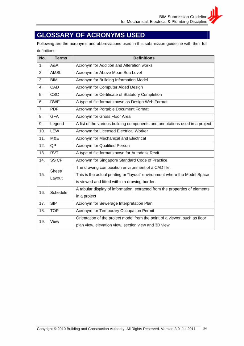
BIM Submission Guideline for Mechanical, Electrical & Plumbing Discipline
Copyright © 2010 Building and Construction Authority. All Rights Reserved. Version 3.0 Jul.2011 56
GLOSSARY OF ACRONYMS USED Following are the acronyms and abbreviations used in this submission guideline with their full
definitions:
No. Terms Definitions
1. A&A Acronym for Addition and Alteration works
2. AMSL Acronym for Above Mean Sea Level
3. BIM Acronym for Building Information Model
4. CAD Acronym for Computer Aided Design
5. CSC Acronym for Certificate of Statutory Completion
6. DWF A type of file format known as Design Web Format
7. PDF Acronym for Portable Document Format
8. GFA Acronym for Gross Floor Area
9. Legend A list of the various building components and annotations used in a project
10. LEW Acronym for Licensed Electrical Worker
11. M&E Acronym for Mechanical and Electrical
12. QP Acronym for Qualified Person
13. RVT A type of file format known for Autodesk Revit
14. SS CP Acronym for Singapore Standard Code of Practice
15. Sheet/
Layout
The drawing composition environment of a CAD file.
This is the actual printing or ―layout‖ environment where the Model Space
is viewed and fitted within a drawing border.
16. Schedule A tabular display of information, extracted from the properties of elements
in a project
17. SIP Acronym for Sewerage Interpretation Plan
18. TOP Acronym for Temporary Occupation Permit
19. View Orientation of the project model from the point of a viewer, such as floor
plan view, elevation view, section view and 3D view

BIM Submission Guideline for Mechanical, Electrical & Plumbing Discipline
Copyright © 2010 Building and Construction Authority. All Rights Reserved. Version 3.0 Jul.2011 57
OBJECT LIBRARIES
Missing Objects in BIM tool
Object Discipline Supplier / Manufacturer

BIM Submission Guideline for Mechanical, Electrical & Plumbing Discipline
Copyright © 2010 Building and Construction Authority. All Rights Reserved. Version 3.0 Jul.2011 58
NOTES
______________________________________________________________
______________________________________________________________
______________________________________________________________
______________________________________________________________
______________________________________________________________
______________________________________________________________
______________________________________________________________
______________________________________________________________
______________________________________________________________
______________________________________________________________
______________________________________________________________
______________________________________________________________
______________________________________________________________
______________________________________________________________
______________________________________________________________
______________________________________________________________
______________________________________________________________
______________________________________________________________
______________________________________________________________
______________________________________________________________
______________________________________________________________
______________________________________________________________
______________________________________________________________
______________________________________________________________
______________________________________________________________
______________________________________________________________
______________________________________________________________
______________________________________________________________
______________________________________________________________
______________________________________________________________
______________________________________________________________


![GUIDELINE ON SUBMISSION OF DOCUMENTATION … · working document qas/10.373. [draft, 2010-08-10] restricted 1 2 3 4 5 guideline on submission of documentation for a 6 multisource](https://static.fdocuments.in/doc/165x107/5b1580007f8b9a1a398cc225/guideline-on-submission-of-documentation-working-document-qas10373-draft.jpg)