
E SUB-COMMITTEE ON CARRIAGE OF CCC 1/13/Add.1 CARGOES …
129
I:\CCC\01\13-Add-1.doc E SUB-COMMITTEE ON CARRIAGE OF CARGOES AND CONTAINERS 1st session Agenda item 13 CCC 1/13/Add.1 30 September 2014 Original: ENGLISH REPORT TO THE MARITIME SAFETY COMMITTEE Attached is annex 4 (Draft International Code of Safety for Ships Using Gases or Other Low-Flashpoint Fuels (IGF Code)) to the report of the Sub-Committee on Carriage of Cargoes and Containers on its first session (CCC 1/13).
Transcript of E SUB-COMMITTEE ON CARRIAGE OF CCC 1/13/Add.1 CARGOES …

I:\CCC\01\13-Add-1.doc
E
SUB-COMMITTEE ON CARRIAGE OF CARGOES AND CONTAINERS 1st session Agenda item 13
CCC 1/13/Add.1
30 September 2014 Original: ENGLISH
REPORT TO THE MARITIME SAFETY COMMITTEE Attached is annex 4 (Draft International Code of Safety for Ships Using Gases or Other Low-Flashpoint Fuels (IGF Code)) to the report of the Sub-Committee on Carriage of Cargoes and Containers on its first session (CCC 1/13).

CCC 1/13/Add.1 Page 2
I:\CCC\01\13-Add-1.doc
LIST OF ANNEXES
ANNEX 4 DRAFT INTERNATIONAL CODE OF SAFETY FOR SHIPS USING GASES OR OTHER LOW-FLASHPOINT FUELS (IGF CODE)
(See document CCC 1/13 for annexes 1 to 3 and 5 to 10)
***

CCC 1/13/Add.1 Annex 4, page 1
I:\CCC\01\13-Add-1.doc
ANNEX 4
DRAFT INTERNATIONAL CODE OF SAFETY FOR SHIPS USING GASES OR OTHER LOW-FLASHPOINT FUELS (IGF CODE)
INDEX
Section Page 1 Preamble ................................................................................................................... 8
PART A ................................................................................................................................... 9
2 GENERAL .................................................................................................................... 9
2.1 Application ............................................................................................................... 9
2.2 Definitions ................................................................................................................ 9
2.3 Alternative design .................................................................................................. 12
3 GOAL AND FUNCTIONAL REQUIREMENTS .................................................................... 12
3.1 Goal ......................................................................................................................... 12
3.2 Functional requirements ....................................................................................... 12
4 GENERAL REQUIREMENTS ......................................................................................... 13
4.1 Goal ......................................................................................................................... 13
4.2 Risk assessment.................................................................................................... 13
4.3 Limitation of explosion consequences ............................................................... 14
PART A-1 SPECIFIC REQUIREMENTS FOR SHIPS USING NATURAL GAS AS FUEL 15
5 SHIP DESIGN AND ARRANGEMENT .............................................................................. 15
5.1 Goal ......................................................................................................................... 15
5.2 Functional requirements ....................................................................................... 15
5.3 Regulations – General ........................................................................................... 15
5.4 Machinery space concepts ................................................................................... 18
5.5 Regulations for gas safe machinery space ......................................................... 19
5.6 Regulations for ESD-protected machinery spaces ............................................ 19
5.7 Regulations for location and protection of fuel piping ...................................... 20
5.8 Regulations for fuel preparation room design .................................................... 20
5.9 Regulations for bilge systems .............................................................................. 20
5.10 Regulations for drip trays ..................................................................................... 21
5.11 Regulations for arrangement of entrances and other openings ....................... 21
5.12 Regulations for air locks ....................................................................................... 21
6 FUEL CONTAINMENT SYSTEM ..................................................................................... 22
6.1 Goal ......................................................................................................................... 22

CCC 1/13/Add.1 Annex 4, page 2
I:\CCC\01\13-Add-1.doc
6.2 Functional requirements ....................................................................................... 22
6.3 Regulations – General ........................................................................................... 23
6.4 Regulations for liquefied gas fuel containment .................................................. 24
6.4.1 General .................................................................................................................... 24
6.4.2 Liquefied gas fuel containment safety principles ............................................... 26
6.4.3 Secondary barriers in relation to tank types ....................................................... 26
6.4.4 Design of secondary barriers ............................................................................... 27
6.4.5 Partial secondary barriers ..................................................................................... 28
6.4.6 Supporting arrangements ..................................................................................... 28
6.4.7 Associated structure and equipment ................................................................... 28
6.4.8 Thermal insulation ................................................................................................. 29
6.4.9 Design loads ........................................................................................................... 29
6.4.9.1 General .................................................................................................................... 29
6.4.9.2 Permanent loads ...................................................................................................... 29
6.4.9.3 Functional loads ....................................................................................................... 29
6.4.9.4 Environmental loads ................................................................................................ 34
6.4.9.5 Accidental loads ....................................................................................................... 35
6.4.10 Structural integrity ................................................................................................. 36
6.4.10.1 General .................................................................................................................... 36
6.4.11 Structural analysis ................................................................................................. 36
6.4.12 Design conditions .................................................................................................. 37
6.4.13 Materials and construction ................................................................................... 41
6.4.13.1 Materials .................................................................................................................. 41
6.4.13.2 Materials of primary and secondary barriers ............................................................ 42
6.4.13.3 Thermal insulation and other materials used in liquefied gas fuel containment
systems ................................................................................................................... 43
6.4.14 Construction processes ........................................................................................ 45
6.4.14.1 Weld joint design ...................................................................................................... 45
6.4.14.2 Design for gluing and other joining processes ......................................................... 45
6.4.15 Tank types .............................................................................................................. 45
6.4.15.1 Type A independent tanks ....................................................................................... 45
6.4.15.2 Type B independent tanks ....................................................................................... 47
6.4.15.3 Type C independent tanks ....................................................................................... 49
6.4.15.4 Membrane tanks ...................................................................................................... 53
6.4.16 Limit state design for novel concepts ....................................................................... 56

CCC 1/13/Add.1 Annex 4, page 3
I:\CCC\01\13-Add-1.doc
6.5 Regulations for portable tanks ............................................................................. 56
6.6 Regulations for compressed gas fuel containment ........................................... 57
6.7 Regulations for pressure relief system ............................................................... 58
6.7.1 General .................................................................................................................... 58
6.7.2 Pressure relief systems for liquefied gas fuel tanks. ......................................... 58
6.7.3 Sizing of pressure relieving system ..................................................................... 60
6.7.3.1 Sizing of pressure relief valves ................................................................................ 60
6.7.3.2 Sizing of vent pipe system ....................................................................................... 63
6.8 Regulations on filling limit for liquefied gas fuel tanks ..................................... 64
6.9 Regulations for the maintaining of fuel storage condition ................................ 64
6.9.1 Control of tank pressure and temperature .......................................................... 64
6.9.2 Design of systems ................................................................................................. 65
6.9.3 Reliquefaction systems ......................................................................................... 65
6.9.4 Thermal oxidation systems ................................................................................... 65
6.9.5 Compatibility .......................................................................................................... 65
6.9.6 Availability of systems .......................................................................................... 65
6.10 Regulations on atmospheric control within the fuel storage system ............... 66
6.11 Regulations on atmosphere control within hold spaces (Fuel containment
systems other than type C independent tanks) .................................................. 66
6.12 Regulations on environmental control of spaces surrounding type C
independent tanks ................................................................................................. 66
6.13 Regulations on inerting ......................................................................................... 66
6.14 Regulations on inert gas production and storage on board ............................. 67
7 MATERIAL AND GENERAL PIPE DESIGN ....................................................................... 67
7.1 Goal ......................................................................................................................... 67
7.2 Functional requirements ....................................................................................... 67
7.3 Regulations for general pipe design .................................................................... 68
7.3.1 General .................................................................................................................... 68
7.3.2 Wall thickness ........................................................................................................ 68
7.3.3 Design condition .................................................................................................... 69
7.3.4 Allowable stress ..................................................................................................... 69
7.3.5 Flexibility of piping ................................................................................................ 70
7.3.6 Piping fabrication and joining details .................................................................. 70
7.4 Regulations for materials ...................................................................................... 72
7.4.1 Metallic materials ................................................................................................... 72

CCC 1/13/Add.1 Annex 4, page 4
I:\CCC\01\13-Add-1.doc
8 BUNKERING .............................................................................................................. 77
8.1 Goal ......................................................................................................................... 77
8.2 Functional requirements ....................................................................................... 77
8.3 Regulations for bunkering station ....................................................................... 77
8.3.1 General ................................................................................................................... 77
8.3.2 Ships' fuel hoses ................................................................................................... 78
8.4 Regulations for manifold ...................................................................................... 78
8.5 Regulations for bunkering system ....................................................................... 78
9 FUEL SUPPLY TO CONSUMERS .................................................................................. 78
9.1 Goal ......................................................................................................................... 78
9.2 Functional requirements ....................................................................................... 79
9.3 Regulations on redundancy of fuel supply ......................................................... 79
9.4 Regulations on safety functions of gas supply system ..................................... 79
9.5 Regulations for fuel distribution outside of machinery space .......................... 80
9.6 Regulations for fuel supply to consumers in gas-safe machinery spaces ...... 80
9.7 Regulations for gas fuel supply to consumers in ESD-protected machinery
spaces .................................................................................................................... 81
9.8 Regulations for the design of ventilated duct, outer pipe against inner pipe
gas leakage ............................................................................................................ 81
9.9 Regulations for compressors and pumps ........................................................... 82
10 POWER GENERATION INCLUDING PROPULSION AND OTHER GAS CONSUMERS .............. 83
10.1 Goal ......................................................................................................................... 83
10.2 Functional requirements ....................................................................................... 83
10.3 Regulations for internal combustion engines of Piston type ............................ 83
10.3.1 General .................................................................................................................... 83
10.3.2 Regulations for dual fuel engines ........................................................................ 84
10.3.3 Regulations for gas-only engines ........................................................................ 84
10.3.4 Regulations for multi-fuel engines ....................................................................... 84
10.4 Regulations for main and auxiliary boilers ......................................................... 84
10.5 Regulations for gas turbines ................................................................................ 85
11 FIRE SAFETY ............................................................................................................. 86
11.1 Goal ......................................................................................................................... 86
11.2 Functional requirements ....................................................................................... 86
11.3 Regulations for fire protection ............................................................................. 86
11.4 Reguulations for fire main .................................................................................... 87
11.5 Regulations for water spray system .................................................................... 87

CCC 1/13/Add.1 Annex 4, page 5
I:\CCC\01\13-Add-1.doc
11.6 Regulations for dry chemical powder fire-extinguishing system ..................... 87
11.7 Regulations for fire detection and alarm system ............................................... 88
12 EXPLOSION PREVENTION ............................................................................................ 88
12.1 Goal ......................................................................................................................... 88
12.2 Functional requirements ....................................................................................... 88
12.3 Regulations - General ............................................................................................ 88
12.4 Regulations on area classification ....................................................................... 89
12.5 Hazardous area zones ........................................................................................... 89
13 VENTILATION ............................................................................................................. 90
13.1 Goal ......................................................................................................................... 90
13.2 Functional requirements ....................................................................................... 90
13.3 Regulations – General ........................................................................................... 90
13.4 Regulations for tank connection space ............................................................... 92
13.5 Regulations for machinery spaces ...................................................................... 92
13.6 Regulations for fuel preparation room ................................................................ 93
13.7 Regulations for bunkering station ....................................................................... 93
13.8 Regulations for ducts and double pipes ............................................................. 93
14 ELECTRICAL INSTALLATIONS ..................................................................................... 93
14.1 Goal ......................................................................................................................... 93
14.2 Functional requirements ....................................................................................... 93
14.3 Regulations - General ............................................................................................ 94
15 CONTROL, MONITORING AND SAFETY SYSTEMS .......................................................... 94
15.1 Goal ......................................................................................................................... 94
15.2 Functional requirements ....................................................................................... 95
15.3 Regulations – General ........................................................................................... 95
15.4 Regulations for bunkering and gas tank monitoring ......................................... 95
15.5 Regulations for bunkering control ....................................................................... 97
15.6 Regulations for gas compressor monitoring ...................................................... 97
15.7 Regulations for gas engine monitoring ............................................................... 97
15.8 Regulations for gas detection .............................................................................. 98
15.9 Regulations for fire detection ............................................................................... 99
15.10 Regulations for ventilation ................................................................................... 99
15.11 Regulations on safety functions of fuel supply systems .................................. 99

CCC 1/13/Add.1 Annex 4, page 6
I:\CCC\01\13-Add-1.doc
ANNEX STANDARD FOR THE USE OF LIMIT STATE METHODOLOGIES IN THE DESIGN OF FUEL
CONTAINMENT SYSTEMS OF NOVEL CONFIGURATION ................................................. 103
PART B ............................................................................................................................... 111
16 MANUFACTURE, WORKMANSHIP AND TESTING .......................................................... 111
16.1 General ................................................................................................................. 111
16.2 General test regulations and specifications ..................................................... 111
16.2.1 Tensile test ........................................................................................................... 111
16.2.2 Toughness test .................................................................................................... 111
16.2.3 Bend test .............................................................................................................. 113
16.2.4 Section observation and other testing .............................................................. 113
16.3 Welding of metallic materials and non-destructive testing for the fuel
containment system ............................................................................................ 113
16.3.1 General ................................................................................................................. 113
16.3.2 Welding consumables ......................................................................................... 113
16.3.3 Welding procedure tests for fuel tanks and process pressure vessels ......... 113
16.3.4 Welding procedure tests for piping ................................................................... 115
16.3.5 Production weld tests ......................................................................................... 115
16.3.6 Non-destructive testing ....................................................................................... 115
16.4 Other regulations for construction in metallic materials ................................. 117
16.4.1 General ................................................................................................................. 117
16.4.2 Independent tank ................................................................................................. 117
16.4.3 Secondary barriers .............................................................................................. 117
16.4.4 Membrane tanks .................................................................................................. 117
16.5 Testing .................................................................................................................. 117
16.5.1 Testing and inspections during construction ................................................... 117
16.5.2 Type A independent tanks .................................................................................. 118
16.5.3 Type B independent tanks .................................................................................. 118
16.5.4 Type C independent tanks and other pressure vessels .................................. 118
16.5.5 Membrane tanks .................................................................................................. 119
16.6 Welding, post-weld heat treatment and non-destructive testing .................... 120
16.6.1 General ................................................................................................................. 120
16.6.2 Post-weld heat treatment .................................................................................... 120
16.6.3 Non-destructive testing ....................................................................................... 120
16.7 Testing regulations .............................................................................................. 121
16.7.1 Type testing of piping components ................................................................... 121
16.7.2 Expansion bellows .............................................................................................. 121

CCC 1/13/Add.1 Annex 4, page 7
I:\CCC\01\13-Add-1.doc
16.7.3 System testing regulations ................................................................................. 122
PART C ............................................................................................................................... 123
17 TRAINING ................................................................................................................ 123
17.1 Goal ....................................................................................................................... 123
17.2 Functional requirements ..................................................................................... 123
17.3 Drills and emergency exercises ......................................................................... 123
18 OPERATION ............................................................................................................. 123
18.1 Goal ....................................................................................................................... 123
18.2 Functional requirements ..................................................................................... 123
18.3 Regulations for maintenance ............................................................................. 124
18.4 Regulations for bunkering operations ............................................................... 124
18.4.1 Responsibilities ................................................................................................... 124
18.4.2 Overview of control, automation and safety systems ...................................... 124
18.4.3 Pre-bunkering verification .................................................................................. 125
18.4.4 Ship bunkering source communications .......................................................... 125
18.4.5 Electrical bonding ................................................................................................ 126
18.4.6 Conditions for transfer ........................................................................................ 126
18.5 Regulations for enclosed space entry ............................................................... 126
18.6 Regulations for inerting and purging of fuel systems ..................................... 127
18.7 Regulations for hot work on or near fuel systems ........................................... 127
CCC 1/13/Add.1 Annex 4, page 8
I:\CCC\01\13-Add-1.doc
1 PREAMBLE The purpose of this Code is to provide an international standard for ships using low-flashpoint fuel, other than vessels covered by the IGC Code. The basic philosophy of this Code is to provide mandatory provisions for the arrangement, installation, control and monitoring of machinery, equipment and systems using low-flashpoint fuel to minimize the risk to the ship, its crew and the environment, having regard to the nature of the fuels involved. Throughout the development of this Code it was recognized that it must be based upon sound naval architectural and engineering principles and the best understanding available of current operational experience, field data and research and development. Due to the rapidly evolving new fuels technology, the Organization will periodically review this Code, taking into account both experience and technical developments. This Code addresses all areas that need special consideration for the usage of the low-flashpoint fuel. The basic philosophy of the IGF Code considers the goal based approach (MSC.1/Circ.1394). Therefore, goals and functional requirements were specified for each section forming the basis for the design, construction and operation. The current version of this Code includes regulations to meet the functional requirements for natural gas fuel. Regulations for other low-flashpoint fuels will be added to this Code as, and when, they are developed by the Organization. In the meantime, for other low-flashpoint fuels, compliance with the functional requirements of this Code must be demonstrated through alternative design.

CCC 1/13/Add.1 Annex 4, page 9
I:\CCC\01\13-Add-1.doc
PART A 2 GENERAL 2.1 Application Unless expressly provided otherwise this Code applies to ships to which part G of SOLAS chapter II-1 applies. 2.2 Definitions Unless otherwise stated below, definitions are as defined in SOLAS chapter II-2. 2.2.1 Accident means an uncontrolled event that may entail the loss of human life, personal injuries, environmental damage or the loss of assets and financial interests. 2.2.2 Breadth (B) means the greatest moulded breadth of the ship at or below the deepest draught (summer load line draught). Refer to SOLAS regulation II-1/2.8. 2.2.3 Bunkering means the transfer of liquid or gaseous fuel from land based or floating facilities into a ships' permanent tanks or connection of portable tanks to the fuel supply system. 2.2.4 Certified safe type means electrical equipment that is certified safe by the relevant authorities recognized by the Administration or its recognized organization acting on its behalf for operation in a flammable atmosphere based on a recognized standard.1
2.2.5 CNG means compressed natural gas (see also 2.2.25).
2.2.6 Control station means those spaces defined in SOLAS chapter II-2 and additionally for this Code, the engine control room.
2.2.7 Design temperature for selection of materials is the minimum temperature at which liquefied gas fuel may be loaded or transported in the liquefied gas fuel tanks.
2.2.8 Design vapour pressure "P0" is the maximum gauge pressure, at the top of the tank, to be used in the design of the tank.
2.2.9 Double block and bleed valve means a set of two valves in series in a pipe and a third valve enabling the pressure release from the pipe between those two valves. The arrangement may also consist of a two-way valve and a closing valve instead of three separate valves. 2.2.10 Dual fuel engines means engines that employ fuel covered by this Code (with pilot fuel) and oil fuel. Oil fuels may include distillate and residual fuels. 2.2.11 Enclosed space means any space within which, in the absence of artificial ventilation, the ventilation will be limited and any explosive atmosphere will not be dispersed naturally.2
1 Refer to IEC 60079 series, Explosive atmospheres and IEC 60092-502:1999 Electrical Installations in
Ships – Tankers – Special Features. 2 See also definition in IEC 60092-502:1999.

CCC 1/13/Add.1 Annex 4, page 10
I:\CCC\01\13-Add-1.doc
2.2.12 ESD means emergency shutdown. 2.2.13 Explosion means a deflagration event of uncontrolled combustion. 2.2.14 Explosion pressure relief means measures provided to prevent the explosion pressure in a container or an enclosed space exceeding the maximum overpressure the container or space is designed for, by releasing the overpressure through designated openings. 2.2.15 Fuel containment system is the arrangement for the storage of fuel including tank connections. It includes where fitted, a primary and secondary barrier, associated insulation and any intervening spaces, and adjacent structure if necessary for the support of these elements. If the secondary barrier is part of the hull structure it may be a boundary of the fuel storage hold space. The spaces around the fuel tank are defined as follows:
.1 Fuel storage hold space is the space enclosed by the ship's structure in which a fuel containment system is situated. If tank connections are located in the fuel storage hold space, it will also be a tank connection space;
.2 Interbarrier space is the space between a primary and a secondary barrier,
whether or not completely or partially occupied by insulation or other material; and
.3 Tank connection space is a space surrounding all tank connections and
tank valves that is required for tanks with such connections in enclosed spaces.
2.2.16 Fuel preparation room means any space containing pumps, compressors and/or vaporizers for fuel preparation purposes. 2.2.17 Gas means a fluid having a vapour pressure exceeding 2.8 bar absolute at a temperature of 37.8°C. 2.2.18 Gas consumer means any unit within the vessel using gas as a fuel. 2.2.19 Gas only engine means an engine capable of operating on gas-only, and not able to switch over to operation on any other type of fuel. 2.2.20 Hazardous area means an area in which an explosive gas atmosphere or a flammable gas or vapour is or may be expected to be present, in quantities such as to require special precautions for the construction, installation and use of electrical apparatus or any other equipment that may provide potential sources of ignition. 2.2.21 High pressure means a maximum working pressure greater than 10 bar. 2.2.22 Independent tanks are self-supporting, do not form part of the ship's hull and are not essential to the hull strength. 2.2.23 LEL means the lower explosive limit. 2.2.24 Length (L) is the length as defined in the International Convention on Load Lines in force.

CCC 1/13/Add.1 Annex 4, page 11
I:\CCC\01\13-Add-1.doc
2.2.25 LNG means liquefied natural gas. 2.2.26 Low-flashpoint fuel means gaseous or liquid fuel having a flashpoint lower than otherwise permitted under paragraph 2.1.1 of SOLAS regulation II-2/4. 2.2.27 MARVS means the maximum allowable relief valve setting. 2.2.28 MAWP means the maximum allowable working pressure of a system component or tank. 2.2.29 Membrane tanks are non-self-supporting tanks that consist of a thin liquid and gas tight layer (membrane) supported through insulation by the adjacent hull structure. 2.2.30 Multi-fuel engines means engines that can use two or more different fuels that are separate from each other. 2.2.31 Non-hazardous area means an area which is not considered to be hazardous, i.e. gas safe, provided certain conditions are being met. 2.2.32 Open deck means a deck having no significant fire risk that at least is open on both ends/sides, or is open on one end and is provided with adequate natural ventilation that is effective over the entire length of the deck through permanent openings distributed in the side plating or deckhead. 2.2.33 Recognized organization means an organization that has been assessed by a flag State, and found to comply with part 2 of the Code for Recognized Organizations (RO Code). 2.2.34 Risk is an expression for the combination of the likelihood and the severity of the consequences. 2.2.35 Secondary barrier is the liquid-resisting outer element of a fuel containment system designed to afford temporary containment of any envisaged leakage of liquid fuel through the primary barrier and to prevent the lowering of the temperature of the ship's structure to an unsafe level. 2.2.36 Semi-enclosed space means a space where the natural conditions of ventilation are notably different from those on open deck due to the presence of structure such as roofs, windbreaks and bulkheads and which are so arranged that dispersion of gas may not occur.3 2.2.37 Source of release means equipment from which a gas, vapour, mist or liquid may be released into the atmosphere so that an explosive atmosphere may be formed under normal operating conditions, for example valves and flanges in fuel piping systems. 2.2.38 Unacceptable loss of power means that it is not possible to sustain or restore normal operation of the propulsion machinery in the event of one of the essential auxiliaries becoming inoperative, in accordance with SOLAS regulation II-1/26.3. 2.2.39 Vapour pressure is the equilibrium pressure of the saturated vapour above the liquid, expressed in bar absolute at a specified temperature.
3 Refer also to IEC 60092-502:1999 Electrical Installations in Ships – Tankers – Special Features.
CCC 1/13/Add.1 Annex 4, page 12
I:\CCC\01\13-Add-1.doc
2.3 Alternative design 2.3.1 This Code contains functional requirements for all appliances and arrangements related to the usage of low-flashpoint fuels. 2.3.2 Fuels, appliances and arrangements of low-flashpoint fuel systems may either:
.1 deviate from those set out in this Code, or .2 be designed for use of a fuel not specifically addressed in this Code.
Such fuels, appliances and arrangements can be used provided that these meet the intent of the goal and functional requirements concerned and provide an equivalent level of safety of the relevant chapters. 2.3.3 The equivalence of the alternative design shall be demonstrated as specified in SOLAS regulation II-1/55 and approved by the Administration. However, the Administration shall not allow operational methods or procedures to be applied as an alternative to a particular fitting, material, appliance, apparatus, item of equipment, or type thereof which is prescribed by this Code. 3 GOAL AND FUNCTIONAL REQUIREMENTS
3.1 Goal
The goal of this Code is to provide for safe and environmentally-friendly design, construction and operation of ships and in particular their installations of systems for propulsion machinery, auxiliary power generation machinery and/or other purpose machinery using gas or low-flashpoint fuel as fuel.
3.2 Functional requirements
3.2.1 The safety, reliability and dependability of the systems shall be equivalent to that achieved with new and comparable conventional oil-fuelled main and auxiliary machinery.
3.2.2 The probability and consequences of fuel-related hazards shall be limited to a minimum through arrangement and system design, such as ventilation, detection and safety actions. In the event of gas leakage or failure of the risk reducing measures, necessary safety actions shall be initiated. 3.2.3 The design philosophy shall ensure that risk reducing measures and safety actions for the gas fuel installation do not lead to an unacceptable loss of power. 3.2.4 Hazardous areas shall be restricted, as far as practicable, to minimize the potential risks that might affect the safety of the ship, persons on board, and equipment. 3.2.5 Equipment installed in hazardous areas shall be minimized to that required for operational purposes and shall be suitably and appropriately certified. 3.2.6 Unintended accumulation of explosive, flammable or toxic gas concentrations shall be prevented. 3.2.7 System components shall be protected against external damages.

CCC 1/13/Add.1 Annex 4, page 13
I:\CCC\01\13-Add-1.doc
3.2.8 Sources of ignition in hazardous areas shall be eliminated to reduce the probability of explosions. 3.2.9 It shall be arranged for safe and suitable, fuel supply, storage and bunkering arrangements capable of receiving and containing the fuel in the required state without leakage. Other than when necessary for safety reasons, the system shall be designed to prevent venting under all normal operating conditions including idle periods. 3.2.10 Piping systems, containment and over-pressure relief arrangements that are of suitable design, construction and installation for their intended application shall be provided. 3.2.11 Machinery, systems and components shall be designed, constructed, installed, operated, maintained and protected to ensure safe and reliable operation. 3.2.12 Fuel containment system and machinery spaces containing source that might release gas into the space shall be arranged and located such that a fire or explosion in either will not lead to an unacceptable loss of power or render equipment in other compartments inoperable. 3.2.13 Suitable control, alarm, monitoring and shutdown systems shall be provided to ensure safe and reliable operation. 3.2.14 Fixed gas detection suitable for all spaces and areas concerned shall be arranged. 3.2.15 Fire detection, protection and extinction measures appropriate to the hazards concerned shall be provided. 3.2.16 Commissioning, trials and maintenance of fuel systems and gas utilization machinery shall satisfy the goal in terms of safety, availability and reliability. 3.2.17 The technical documentation shall permit an assessment of the compliance of the system and its components with the applicable rules, guidelines, design standards used and the principles related to safety, availability, maintainability and reliability. 3.2.18 A single failure in a technical system or component shall not lead to an unsafe or unreliable situation. 4 GENERAL REQUIREMENTS 4.1 Goal The goal of this chapter is to ensure that the necessary assessments of the risks involved are carried out in order to eliminate or mitigate any adverse effect to the persons on board, the environment or the ship. 4.2 Risk assessment 4.2.1 A risk assessment shall be conducted to ensure that risks arising from the use of low-flashpoint fuels affecting persons on board, the environment, the structural strength or the integrity of the ship are addressed. Consideration shall be given to the hazards associated with physical layout, operation and maintenance, following any reasonably foreseeable failure.

CCC 1/13/Add.1 Annex 4, page 14
I:\CCC\01\13-Add-1.doc
4.2.2 The risks shall be analysed using acceptable and recognized risk analysis techniques, and loss of function, component damage, fire, explosion and electric shock shall as a minimum be considered. The analysis shall ensure that risks are eliminated wherever possible. Risks which cannot be eliminated shall be mitigated as necessary. Details of risks, and the means by which they are mitigated, shall be documented to the satisfaction of the Administration or its recognized organization acting on its behalf.
4.3 Limitation of explosion consequences
An explosion in any space containing any potential sources of release4 and potential ignition sources shall not:
.1 cause damage to or disrupt the proper functioning of equipment/systems located in any space other than that in which the incident occurs;
.2 damage the ship in such a way that flooding of water below the main deck or any progressive flooding occur;
.3 damage work areas or accommodation in such a way that persons who stay in such areas under normal operating conditions are injured;
.4 disrupt the proper functioning of control stations and switchboard rooms
necessary for power distribution;
.5 damage life-saving equipment or associated launching arrangements;
.6 disrupt the proper functioning of firefighting equipment located outside the explosion-damaged space;
.7 affect other areas of the vessel in such a way that chain reactions involving,
inter alia, cargo, gas and bunker oil may arise; or
.8 prevent persons access to life saving appliances or impede escape routes.
4 Double wall fuel pipes are not considered as potential sources of release.

CCC 1/13/Add.1 Annex 4, page 15
I:\CCC\01\13-Add-1.doc
PART A-1
SPECIFIC REQUIREMENTS FOR SHIPS USING NATURAL GAS AS FUEL Fuel in the context of the regulations in this part means natural gas, either in its liquefied or gaseous state. It should be recognized that the composition of natural gas may vary depending on the source of natural gas and the processing of the gas. 5 SHIP DESIGN AND ARRANGEMENT 5.1 Goal The goal of this chapter is to provide for safe location, space arrangements and mechanical protection of power generation equipment, fuel storage system, fuel supply equipment and refuelling systems. 5.2 Functional requirements 5.2.1 This chapter is related to functional requirements in 3.2.1 to 3.2.3, 3.2.5, 3.2.6, 3.2.8, 3.2.12 to 3.2.15 and 3.2.17. In particular the following apply: .1 The fuel tank(s) shall be located in such a way that the probability for
the tank(s) to be damaged following a collision or grounding is reduced to a minimum taking into account the safe operation of the ship and other hazards that may be relevant to the ship.
.2 Fuel containment systems, fuel piping and other fuel sources of release
shall be so located and arranged that released gas is lead to a safe location in the open air.
.3 The access or other openings to spaces containing fuel sources of release
shall be so arranged that flammable, asphyxiating or toxic gas cannot escape to spaces that are not designed for the presence of such gases.
.4 Fuel piping shall be protected against mechanical damage. .5 The propulsion and fuel supply system shall be so designed that safety
actions after any gas leakage do not lead to an unacceptable loss of power. .6 The probability of a gas explosion in a machinery space with gas or
low-flashpoint fuelled machinery shall be minimized. 5.3 Regulations – General 5.3.1 Fuel storage tanks shall be protected against mechanical damage. 5.3.2 Fuel storage tanks and or equipment located on open deck shall be located to ensure sufficient natural ventilation, so as to prevent accumulation of escaped gas.

CCC 1/13/Add.1 Annex 4, page 16
I:\CCC\01\13-Add-1.doc
5.3.3 The fuel tank(s) shall be protected from external damage caused by collision or
grounding in the following way:
.1 The fuel tanks shall be located at a minimum distance of B/5 or 11.5 m, whichever is less, measured inboard from the ship side at right angles to the centreline at the level of the summer load line draught;
where:
B is the greatest moulded breadth of the ship at or below the deepest draught (summer load line draught). Refer to SOLAS regulation II-1/2.8.
.2 In no case shall the boundary of the fuel tank be located closer to the side shell or aft terminal of the ship than as follows:
.1 For passenger ships: B/10; and
.2 For cargo ships:
.1 for Vc below or equal 1,000 m3, 0.8 m;
.2 for 1,000 m3 < Vc < 5,000 m3, 0.75 + Vc x 0.2/4,000 m;
.3 for 5,000 m3 ≤ Vc < 30,000 m3, 0.8 + Vc/25,000 m; and
.4 for Vc ≥ 30,000 m3, 2 m,
where:
Vc corresponds to 100% of the gross design volume of the individual fuel tank at 20°C, including domes and appendages.
.3 The length of the fuel tank or combined projected length of fuel tanks shall not exceed [9][12]% of the ship's length Ls for passenger ships and [12][18]% of the ship's length Ls for cargo ships;
where:
Ls is the greatest projected moulded length of the ship. Refer to SOLAS regulation II-1/2.1.
.4 The lowermost boundary of the fuel tank(s) shall be located above the minimum distance of B/15 or 2.0 m, whichever is less, measured from the moulded line of the bottom shell plating at the centreline.
.5 For multihull ships the value of B may be specially considered.
.6 The fuel tank(s) shall be abaft a transverse plane at 0.08L measured from the forward perpendicular in accordance with SOLAS regulation II-1/8.1 for passenger ships, and abaft the collision bulkhead for cargo ships.
where:
L is the length as defined in the International Convention on Load Lines. Refer to SOLAS regulation II-1/2.5.

CCC 1/13/Add.1 Annex 4, page 17
I:\CCC\01\13-Add-1.doc
5.3.4 As an alternative to 5.3.3.1 and 5.3.3.3 above, the following calculation method may be used to determine the acceptable location of the fuel tanks:
.1 The value fCN calculated as described in the following shall be less than [0.01][0.02] for passenger ships and [0.02][0.04] for cargo ships.5
.2 The fCN is calculated by the following formulation:
fCN = fl x ft x fv
where:
fl is calculated by use of the formulations for factor p contained in SOLAS regulation II-1/7-1.1.1.1. The value of x1 shall correspond to the distance from the aft terminal to the aftmost boundary of the fuel tank and the value of x2 shall correspond to the distance from the aft terminal to the foremost boundary of the fuel tank.
ft is calculated by use of the formulations for factor r contained in SOLAS regulation II-1/7-1.1.2, and reflects the probability that the damage penetrates beyond the outer boundary of the fuel tank. The formulation is:
ft = 1- r (x1,x2,b)
fv is calculated by use of the formulations for factor v contained in SOLAS regulation II-1/7-2.6.1.1 and reflects the probability that the damage is not extending vertically above the lowermost boundary of the fuel tank. The formulations to be used are:
fv = 1.0 - 0.8 · ((H-d) / 7.8), if (H - d) is less than or equal to 7.8 m. fv should not be taken greater than 1.
fv = 0.2 - 0.2 · ((H-d) - 7.8) / 4.7) in all other cases. fv
should not be taken less than 0.
where:
H is the distance from baseline, in metres, to the lowermost boundary of the fuel tank; and
d is the deepest draught (summer load line draught).
.3 The boundaries of each fuel tank are taken as the extreme outer longitudinal, transverse and vertical limits of the tank structure including its tank valves.
.4 For independent tanks the protective distance shall be measured to the tank shell (the primary barrier of the tank containment system). For membrane or semi-membrane tanks the distance shall be measured to the bulkheads surrounding the tank insulation.
5 The value fCN accounts for collision damages that may occur within a zone limited by the longitudinal
projected boundaries of the fuel tank only, and cannot be considered or used as the probability for the fuel tank to become damaged given a collision. The real probability will be higher when accounting for longer damages that include zones forward and aft of the fuel tank.

CCC 1/13/Add.1 Annex 4, page 18
I:\CCC\01\13-Add-1.doc
.5 In no case shall the boundary of the fuel tank be located closer to the side shell or aft terminal of the ship than as follows: .1 For passenger ships: B/10; and
.2 For cargo ships:
.1 for Vc below or equal 1,000 m3, 0.8 m; .2 for 1,000 m3
< Vc < 5,000 m3, 0.75+ Vc x 0.2/4,000 m; .3 for 5,000 m3
≤ Vc < 30,000 m3, 0.8 + Vc/25,000 m; and .4 for Vc ≥ 30,000 m3, 2 m, where:
Vc corresponds to 100% of the gross design volume of the individual fuel tank at 20°C, including domes and appendages.
.6 In case of more than one non-overlapping fuel tank located in the longitudinal
direction, fCN is to be calculated in accordance with paragraph 5.3.4.2 for each fuel tank separately. The value used for the complete fuel tank arrangement is the sum of all values for fCN obtained for each separate tank.
.7 In case the fuel tank arrangement is unsymmetrical about the centreline of
the ship, the calculations of fCN are to be calculated on both starboard and port side and the average value is to be used for the assessment. The minimum distance as set forth in paragraph 5.3.4.5 shall be met on both sides.
.8 For ships with a hull structure providing higher collision and/or grounding
resistance, fuel tank location regulations may be specially considered in accordance with section 2.3.
5.3.5 When fuel is carried in a fuel containment system requiring a complete or partial secondary barrier:
.1 at temperatures below minus 10ºC, fuel storage hold spaces shall be segregated from the sea by a double bottom; and
.2 at temperatures below minus 55ºC, the ship shall also have a longitudinal
bulkhead forming side tanks. 5.4 Machinery space concepts
5.4.1 In order to minimize the probability of a gas explosion in a machinery space with gas-fuelled machinery one of these two alternative concepts may be applied: .1 Gas safe machinery spaces: Arrangements in machinery spaces are such
that the spaces are considered gas safe under all conditions, normal as well as abnormal conditions, i.e. inherently gas safe.
CCC 1/13/Add.1 Annex 4, page 19
I:\CCC\01\13-Add-1.doc
In a gas safe machinery space a single failure cannot lead to release of fuel gas into the machinery space.
.2 ESD-protected machinery spaces: Arrangements in machinery spaces are
such that the spaces are considered non-hazardous under normal conditions, but under certain abnormal conditions may have the potential to become hazardous. In the event of abnormal conditions involving gas hazards, emergency shutdown (ESD) of non-safe equipment (ignition sources) and machinery shall be automatically executed while equipment or machinery in use or active during these conditions shall be of a certified safe type.
In an ESD protected machinery space a single failure may result in a gas release into the space. Venting is designed to accommodate a probable maximum leakage scenario due to technical failures.
Failures leading to dangerous gas concentrations, e.g. gas pipe ruptures or
blow out of gaskets are covered by explosion pressure release devices and ESD arrangements.
5.5 Regulations for gas safe machinery space 5.5.1 A single failure within the fuel system shall not lead to a gas release into the machinery space. 5.5.2 All fuel piping within machinery space boundaries shall be enclosed in a gas tight enclosure in accordance with 9.6. 5.6 Regulations for ESD-protected machinery spaces 5.6.1 ESD protection is limited to machinery spaces that are certified for periodically unattended operation. 5.6.2 Measures shall be applied to protect against explosion, damage of areas outside of the machinery space and ensure redundancy of power supply. The following arrangement shall be provided but may not be limited to:
.1 gas detector;
.2 shut of valve;
.3 redundancy; and
.4 efficient ventilation.
5.6.3 Gas supply piping within machinery spaces may be accepted without a gastight external enclosure on the following conditions:
.1 Engines for generating propulsion power and electric power shall be located in two or more machinery spaces not having any common boundaries unless it can be documented that a single casualty will not affect both spaces.
CCC 1/13/Add.1 Annex 4, page 20
I:\CCC\01\13-Add-1.doc
.2 The gas machinery space shall contain only a minimum of such necessary equipment, components and systems as are required to ensure that the gas machinery maintains its function.
.3 A fixed gas detection system arranged to automatically shut down the gas
supply, and disconnect all electrical equipment or installations not of a certified safe type, shall be fitted.
5.6.4 Distribution of engines between the different machinery spaces shall be such that shutdown of fuel supply to any one machinery space does not lead to an unacceptable loss of power. 5.6.5 ESD protected machinery spaces separated by a single bulkhead shall have sufficient strength to withstand the effects of a local gas explosion in either space, without affecting the integrity of the adjacent space and equipment within that space. 5.6.6 ESD protected machinery spaces shall be designed to provide a geometrical shape that will minimize the accumulation of gases or formation of gas pockets. 5.6.7 The ventilation system of ESD-protected machinery spaces shall be arranged in accordance with 13.5. 5.7 Regulations for location and protection of fuel piping 5.7.1 Fuel pipes shall not be located less than [760] mm from the ship's side. 5.7.2 Fuel piping shall not be led directly through accommodation spaces, service spaces, electrical equipment rooms or control stations as defined in the SOLAS Convention. 5.7.3 Fuel pipes led through ro-ro spaces, special category spaces and on open decks shall be protected against mechanical damage. 5.7.4 Gas fuel piping in ESD protected machinery spaces shall be located as far as practicable from the electrical installations and tanks containing flammable liquids. 5.7.5 Gas fuel piping in ESD protected machinery spaces shall be protected against mechanical damage. 5.8 Regulations for fuel preparation room design 5.8.4 Fuel preparation rooms shall be located on an open deck, unless those rooms are arranged and fitted in accordance with the regulations of this Code for tank connection spaces.
5.9 Regulations for bilge systems
5.9.1 Bilge systems installed in areas where fuel covered by this Code can be present shall be segregated from the bilge system of spaces where fuel cannot be present. 5.9.2 Where fuel is carried in a fuel containment system requiring a secondary barrier, suitable drainage arrangements for dealing with any leakage into the hold or insulation spaces through the adjacent ship structure shall be provided. The bilge system shall not lead to pumps in safe spaces. Means of detecting such leakage shall be provided.
CCC 1/13/Add.1 Annex 4, page 21
I:\CCC\01\13-Add-1.doc
5.9.3 The hold or interbarrier spaces of type A independent tanks for liquid gas shall be provided with a drainage system suitable for handling liquid fuel in the event of fuel tank leakage or rupture. 5.10 Regulations for drip trays 5.10.1 Drip trays shall be fitted where leakage may occur which can cause damage to the ship structure or where limitation of the area which is effected from a spill is necessary. 5.10.2 Drip trays shall be made of suitable material. 5.10.3 The drip tray shall be thermally insulated from the ship's structure so that the surrounding hull or deck structures are not exposed to unacceptable cooling, in case of leakage of liquid fuel. 5.10.4 Each tray shall be fitted with a drain valve to enable rain water to be drained over the ship's side. 5.10.5 Each tray shall have a sufficient capacity to ensure that the maximum amount of spill according to the risk assessment can be handled. 5.11 Regulations for arrangement of entrances and other openings 5.11.1 Direct access shall not be permitted from a non-hazardous space to a hazardous space. Where such openings are necessary for operational reasons, an air lock which complies with 5.12 shall be provided. 5.11.2 If the fuel preparation room is approved located below deck, the room shall, as far as practicable, have an independent access direct from the open deck. Where a separate access from deck is not practicable, an air lock which complies with 5.12 shall be provided. 5.11.3 Unless access to the tank connection space is independent and direct from open deck it shall be arranged as a bolted hatch. The space containing the bolted hatch will be a hazardous space. 5.11.4 If the access to an ESD-protected machinery space is from another enclosed space in the ship, the entrances shall be arranged with an air lock which complies with 5.12. 5.11.5 For inerted spaces access arrangements shall be such that unintended entry by personnel shall be prevented. If access to such spaces is not from open deck, sealing arrangements shall ensure that leakages of inert gas to adjacent spaces are prevented. 5.12 Regulations for air locks 5.12.1 An air lock is a space enclosed by gastight bulkheads with two substantially gastight doors spaced at least 1.5 m and not more than 2.5 m apart. Unless subject to the requirements of the International Convention on Load Line, the door sill shall not be less than 300 mm in height. The doors shall be self-closing without any holding back arrangements. 5.12.2 Air locks shall be mechanically ventilated at an overpressure relative to the adjacent hazardous area or space.

CCC 1/13/Add.1 Annex 4, page 22
I:\CCC\01\13-Add-1.doc
5.12.3 The air lock shall be designed in a way that no gas can be released to safe spaces in case of the most critical event in the gas dangerous space separated by the air lock. The events shall be evaluated in the risk analysis according to 4.2. 5.12.4 Air locks shall have a simple geometrical form. They shall provide free and easy passage, and shall have a deck area not less than 1.5 m2. Air locks shall not be used for other purposes, for instance as store rooms. 5.12.5 An audible and visual alarm system to give a warning on both sides of the air lock shall be provided to indicate if more than one door is moved from the closed position. 5.12.6 For non-hazardous spaces with access from hazardous open deck where the access is protected by an air lock, electrical equipment which is not of the certified safe type shall be de-energized upon loss of overpressure in the space. 5.12.7 For non-hazardous spaces with access from hazardous spaces below deck where the access is protected by an air lock, upon loss of under pressure in the hazardous space access to the space is to be restricted until the ventilation has been reinstated. Audible and visual alarms shall be given at a manned location to indicate both loss of pressure and opening of the air lock doors when pressure is lost. 5.12.8 Essential equipment required for safety shall not be de-energized and shall be of a certified safe type. This may include lighting, fire detection, public address, general alarms systems. 5.12.9 Electrical equipment which is not of the certified safe type for propulsion, power generation, manoeuvring, anchoring and mooring equipment as well as the emergency fire pumps shall not be located in spaces to be protected by air locks. 6 FUEL CONTAINMENT SYSTEM 6.1 Goal The goal of this chapter is to provide that gas storage is adequate so as to minimize the risk to personnel, the ship and the environment to a level that is equivalent to a conventional oil fuelled ship. 6.2 Functional requirements
This chapter relates to functional requirements in 3.2.1, 3.2.2, 3.2.5 and 3.2.8 to 3.2.17. In particular the following apply:
.1 The fuel containment system shall be so designed that a leak from the tank or its connections does not endanger the ship, persons on board or the environment. Potential dangers to be avoided include:
.1 exposure of ship materials to temperatures below acceptable limits;
.2 flammable fuels spreading to locations with ignition sources;
.3 toxicity potential and risk of oxygen deficiency due to fuels and
inert gases;

CCC 1/13/Add.1 Annex 4, page 23
I:\CCC\01\13-Add-1.doc
.4 restriction of access to muster stations, escape routes and life-saving appliances (LSA); and
.5 reduction in availability of LSA.
.2 The pressure and temperature in the fuel tank shall be kept within the design limits of the containment system and possible carriage requirements of the fuel.
.3 The fuel containment arrangement shall be so designed that safety actions
after any gas leakage do not lead to an unacceptable loss of power.
.4 If portable tanks are used for fuel storage, the design of the fuel containment system shall be equivalent to permanent installed tanks as described in this chapter.
6.3 Regulations – General 6.3.1 Natural gas in a liquid state may be stored with a maximum allowable relief valve setting (MARVS) of up to 10 bar. 6.3.2 The Maximum Allowable Working Pressure (MAWP) of the gas tank shall not exceed 90% of the Maximum Allowable Relief Valve Setting (MARVS). 6.3.3 A fuel containment system located below deck shall be gas tight towards adjacent spaces. 6.3.4 All tank connections, fittings, flanges and tank valves must be enclosed in gas tight tank connection spaces, unless the tank connections are on open deck. The space shall be able to safely contain leakage from the tank in case of leakage from the tank connections. 6.3.5 Pipe connections to the fuel storage tank shall be mounted above the highest liquid level in the tanks, except for fuel storage tanks of type C. Connections below the highest liquid level may however also be accepted for other tank types after special consideration by the Administration or its recognized organization acting on its behalf. 6.3.6 Piping between the tank and the first valve which release liquid in case of pipe failure shall have equivalent safety as the type C tank, with dynamic stress not exceeding the values given in 6.4.15.3.1.2. 6.3.7 The material of the bulkheads of the tank connection space shall have a design temperature corresponding with the lowest temperature it can be subject to in a probable maximum leakage scenario. The tank connection space shall be designed to withstand the maximum pressure build up during such a leakage. Alternatively, pressure relief venting to a safe location (mast) can be provided. 6.3.8 The probable maximum leakage into the tank connection space shall be determined based on detail design, detection and shut down systems. 6.3.9 If piping is connected below the liquid level of the tank it has to be protected by a secondary barrier up to the first valve. 6.3.10 If liquefied gas fuel storage tanks are located on open deck the ship steel shall be protected from potential leakages from tank connections and other sources of leakage by
CCC 1/13/Add.1 Annex 4, page 24
I:\CCC\01\13-Add-1.doc
use of drip trays. The material is to have a design temperature corresponding to the temperature of the fuel carried at atmospheric pressure. The normal operation pressure of the tanks shall be taken into consideration for protecting the steel structure of the ship.
6.3.11 Means shall be provided whereby liquefied gas in the storage tanks can be safely emptied. 6.3.12 It shall be possible to empty, purge and vent fuel storage tanks with fuel piping systems. Instructions for carrying out these procedures must be available on board. Inerting shall be performed with an inert gas prior to venting with dry air to avoid an explosion hazardous atmosphere in tanks and fuel pipes. See detailed regulations in 6.10. 6.4 Regulations for liquefied gas fuel containment 6.4.1 General 6.4.1.1 The risk assessment required in 4.2 shall include evaluation of the vessel's liquefied gas fuel containment system, and may lead to additional safety measures for integration into the overall vessel design. 6.4.1.2 The design life of fixed liquefied gas fuel containment system shall not be less than the design life of the ship or 20 years, whichever is greater. 6.4.1.3 The design life of portable tanks shall not be less than 20 years. 6.4.1.4 Liquefied gas fuel containment systems shall be designed in accordance with North Atlantic environmental conditions and relevant long-term sea state scatter diagrams for unrestricted navigation. Less demanding environmental conditions, consistent with the expected usage, may be accepted by the Administration or its recognized organization acting on its behalf for liquefied gas fuel containment systems used exclusively for restricted navigation. More demanding environmental conditions may be required for liquefied gas fuel containment systems operated in conditions more severe than the North Atlantic environment.6,7 6.4.1.5 Liquefied gas fuel containment systems shall be designed with suitable safety margins:
.1 to withstand, in the intact condition, the environmental conditions
anticipated for the liquefied gas fuel containment system's design life and the loading conditions appropriate for them, which shall include full homogeneous and partial load conditions and partial filling to any intermediate levels; and
.2 being appropriate for uncertainties in loads, structural modelling, fatigue,
corrosion, thermal effects, material variability, aging and construction tolerances.
6.4.1.6 The liquefied gas fuel containment system structural strength shall be assessed against failure modes, including but not limited to plastic deformation, buckling and fatigue.
6 IACS Rec.034 is referred. 7 North Atlantic environmental conditions refer to wave conditions. Assumed temperatures are used for
determining appropriate material qualities with respect to design temperatures and is another matter not intended to be covered in 6.4.1.4.

CCC 1/13/Add.1 Annex 4, page 25
I:\CCC\01\13-Add-1.doc
The specific design conditions that shall be considered for the design of each liquefied gas fuel containment system are given in 6.4.15. There are three main categories of design conditions:
.1 Ultimate Design Conditions – The liquefied gas fuel containment system structure and its structural components shall withstand loads liable to occur during its construction, testing and anticipated use in service, without loss of containment. The design shall take into account proper combinations of the following loads:
.1 internal pressure;
.2 external pressure;
.3 dynamic loads due to the motion of the ship in all loading conditions;
.4 thermal loads;
.5 sloshing loads;
.6 loads corresponding to ship deflections;
.7 tank and liquefied gas fuel weight with the corresponding reaction in way of supports;
.8 insulation weight;
.9 loads in way of towers and other attachments; and
.10 test loads.
.2 Fatigue Design Conditions – The liquefied gas fuel containment system structure and its structural components shall not fail under accumulated cyclic loading.
.3 Accidental Design Conditions – The liquefied gas fuel containment system
shall provide the indicated response to each of the following accident
design conditions (accidental or abnormal events), addressed in this Code:
.1 Collision – The liquefied gas fuel containment system shall withstand the collision loads specified in 6.4.9.5.1 without deformation likely to endanger the tank and its supporting structure.
.2 Fire – The liquefied gas fuel containment systems shall sustain without rupture the rise in internal pressure specified in 6.7.3.1 under the fire scenarios envisaged therein.
.3 Flooded compartment causing buoyancy on tank – the anti-flotation arrangements shall sustain the upward force, specified in 6.4.9.5.2 and there should be no endangering plastic deformation to the fuel containment system and the hull.
6.4.1.7 Measures shall be applied to ensure that scantlings required meet the structural strength provisions and are maintained throughout the design life. Measures may include, but are not limited to, material selection, coatings, corrosion additions, cathodic protection and inerting.

CCC 1/13/Add.1 Annex 4, page 26
I:\CCC\01\13-Add-1.doc
6.4.1.8 An inspection/survey plan for the liquefied gas fuel containment system shall be developed and approved by the Administration or its recognized organization acting on its behalf. The inspection/survey plan shall identify aspects to be examined and/or validated during surveys throughout the liquefied gas fuel containment system's life and, in particular, any necessary in-service survey, maintenance and testing that was assumed when selecting liquefied gas fuel containment system design parameters. The inspection/survey plan may include specific critical locations as per 6.4.12.2.8. 6.4.1.9 Liquefied gas fuel containment systems shall be designed, constructed and equipped to provide adequate means of access to areas that need inspection as specified in the inspection/survey plan. Liquefied gas fuel containment systems, including all associated internal equipment shall be designed and built to ensure safety during operations, inspection and maintenance. 6.4.2 Liquefied gas fuel containment safety principles 6.4.2.1 The containment systems shall be provided with a full secondary liquid-tight barrier capable of safely containing all potential leakages through the primary barrier and, in conjunction with the thermal insulation system, of preventing lowering of the temperature of the ship structure to an unsafe level. 6.4.2.2 The size and configuration or arrangement of the secondary barrier may be reduced or omitted where an equivalent level of safety can be demonstrated in accordance with 6.4.2.3 to 6.4.2.5 as applicable. 6.4.2.3 Liquefied gas fuel containment systems for which the probability for structural failures to develop into a critical state has been determined to be extremely low, but where the possibility of leakages through the primary barrier cannot be excluded, shall be equipped with a partial secondary barrier capable of safely handling and disposing of the leakages. The arrangements shall comply with the following:
.1 failure developments that can be reliably detected before reaching a critical
state (e.g. by gas detection or inspection) shall have a sufficiently long development time for remedial actions to be taken; and
.2 failure developments that cannot be safely detected before reaching
a critical state shall have a predicted development time that is much longer than the expected lifetime of the tank.
6.4.2.4 No secondary barrier is required for liquefied gas fuel containment systems, e.g. type C independent tanks, where the probability for structural failures and leakages through the primary barrier is extremely low and can be neglected. 6.4.2.5 The structural failure/leakage probability level shall be evaluated to validate the design without secondary barrier. 6.4.2.6 For independent tanks requiring full or partial secondary barrier, means for safely disposing of leakages from the tank shall be arranged. 6.4.3 Secondary barriers in relation to tank types Secondary barriers in relation to the tank types defined in 6.4.15 shall be provided in accordance with the following table.

CCC 1/13/Add.1 Annex 4, page 27
I:\CCC\01\13-Add-1.doc
Fuel temperature at atmospheric pressure
-10C and above Below -10C
down to -55C
Below -55C
Basic tank type No secondary barrier required
Hull may act as secondary barrier
Separate secondary barrier where required
Membrane Independent
Type A Type B Type C
Complete secondary barrier Complete secondary barrier Partial secondary barrier No secondary barrier required
6.4.4 Design of secondary barriers 6.4.4.1 Where the liquefied gas fuel temperature at atmospheric pressure is not below minus 55°C, the hull structure may be designed as a secondary barrier based on the following: .1 the hull material shall be suitable for the liquefied gas fuel temperature at
atmospheric pressure as required by 6.4.13.1.1.3; and .2 the design shall be such that this temperature will not result in
unacceptable hull stresses. The location of a containment system using hull structure as secondary barrier shall be specially considered in conjunction with surrounding spaces. 6.4.4.2 The design of the secondary barrier, including spray shield if fitted, shall be such that:
.1 it is capable of containing any envisaged leakage of liquefied gas fuel for a period of 15 days unless different criteria apply for particular voyages, taking into account the load spectrum referred to in 6.4.12.2.6;
.2 physical, mechanical or operational events within the liquefied gas fuel tank
that could cause failure of the primary barrier shall not impair the due function of the secondary barrier, or vice versa;
.3 failure of a support or an attachment to the hull structure will not lead to
loss of liquid tightness of both the primary and secondary barriers;
.4 it is capable of being periodically checked for its effectiveness by means of a visual inspection or other suitable means acceptable to the Administration or its recognized organization acting on its behalf; and
.5 the methods required in 6.4.4.2.4 shall be approved by the Administration
and shall include, as a minimum:
.1 details on the size of defect acceptable and the location within the secondary barrier, before its liquid tight effectiveness is compromised;
.2 accuracy and range of values of the proposed method for detecting
defects in .1 above; .3 scaling factors to be used if full scale model testing is not
undertaken; and

CCC 1/13/Add.1 Annex 4, page 28
I:\CCC\01\13-Add-1.doc
.4 effects of thermal and mechanical cyclic loading on the effectiveness of the proposed test.
.6 The secondary barrier shall fulfil its functional requirements at a static angle
of heel of 30°. 6.4.5 Partial secondary barriers 6.4.5.1 Partial secondary barriers as permitted in 6.4.2.3 shall be a small leak protection system and meet all the regulations in 6.4.4.2. The partial secondary barrier shall include means to detect a leak in the primary barrier, provision such as a spray shield to deflect any liquefied gas fuel down into the partial secondary barrier, and means to dispose of the liquid, which may be by natural evaporation. 6.4.5.2 The capacity of the partial secondary barrier shall be determined, based on the liquefied gas fuel leakage corresponding to the extent of failure resulting from the load spectrum referred to in 6.4.12.2.6, after the initial detection of a primary leak. Due account may be taken of liquid evaporation, rate of leakage, pumping capacity and other relevant factors. 6.4.5.3 The required liquid leakage detection may be by means of liquid sensors, or by an effective use of pressure, temperature or gas detection systems, or any combination thereof. 6.4.5.4 Independent tanks for which the geometry does not present obvious locations for leakage to collect, the partial secondary barrier shall also fulfil its functional requirements at a nominal static angle of trim. 6.4.6 Supporting arrangements 6.4.6.1 The liquefied gas fuel tanks shall be supported by the hull in a manner that prevents bodily movement of the tank under the static and dynamic loads defined in 6.4.9.2 to 6.4.9.5, where applicable, while allowing contraction and expansion of the tank under temperature variations and hull deflections without undue stressing of the tank and the hull. 6.4.6.2 Anti-flotation arrangements shall be provided for independent tanks and capable of withstanding the loads defined in 6.4.9.5.2 without plastic deformation likely to endanger the hull structure. 6.4.6.3 Supports and supporting arrangements shall withstand the loads defined in 6.4.9.3.3.8 and 6.4.9.5, but these loads need not be combined with each other or with wave-induced loads.
6.4.7 Associated structure and equipment
6.4.7.1 Liquefied gas fuel containment systems shall be designed for the loads imposed by associated structure and equipment. This includes pump towers, liquefied gas fuel domes, liquefied gas fuel pumps and piping, stripping pumps and piping, N2 piping, access hatches, ladders, piping penetrations, liquid level gauges, independent level alarm gauges, spray nozzles, and instrumentation systems (such as pressure, temperature and strain gauges).

CCC 1/13/Add.1 Annex 4, page 29
I:\CCC\01\13-Add-1.doc
6.4.8 Thermal insulation
6.4.8.1 Thermal insulation shall be provided as required to protect the hull from temperatures below those allowable and limit the heat flux into the tank to the levels that can be maintained by the pressure and temperature control system applied in 6.9. 6.4.9 Design loads 6.4.9.1 General 6.4.9.1.1 This section defines the design loads that shall be considered with regard to regulations in 6.4.10 to 6.4.12. This includes load categories (permanent, functional, environmental and accidental) and the description of the loads. 6.4.9.1.2 The extent to which these loads shall be considered depends on the type of tank, and is more fully detailed in the following paragraphs. 6.4.9.1.3 Tanks, together with their supporting structure and other fixtures, shall be designed taking into account relevant combinations of the loads described below. 6.4.9.2 Permanent loads 6.4.9.2.1 Gravity loads The weight of tank, thermal insulation, loads caused by towers and other attachments.
6.4.9.2.2 Permanent external loads
Gravity loads of structures and equipment acting externally on the tank. 6.4.9.3 Functional loads 6.4.9.3.1 Loads arising from the operational use of the tank system shall be classified as functional loads. 6.4.9.3.2 All functional loads that are essential for ensuring the integrity of the tank system, during all design conditions, shall be considered. 6.4.9.3.3 As a minimum, the effects from the following criteria, as applicable, shall be considered when establishing functional loads:
.1 internal pressure; .2 external pressure; .3 thermally induced loads; .4 vibration; .5 interaction loads; .6 loads associated with construction and installation; .7 test loads;

CCC 1/13/Add.1 Annex 4, page 30
I:\CCC\01\13-Add-1.doc
.8 static heel loads; .9 weight of liquefied gas fuel; .10 sloshing; .11 wave impacts and green sea effect for tanks installed on open deck; and .12 wind impact as relevant.
6.4.9.3.3.1 Internal pressure
.1 In all cases, including 6.4.9.3.3.1.2, P0 shall not be less than MARVS. .2 For liquefied gas fuel tanks where there is no temperature control and
where the pressure of the liquefied gas fuel is dictated only by the ambient temperature, P0 shall not be less than the gauge vapour pressure of the liquefied gas fuel at a temperature of 45°C except as follows:
.1 Lower values of ambient temperature may be accepted by
the Administration or its recognized organization acting on its behalf for ships operating in restricted areas. Conversely, higher values of ambient temperature may be required.
.2 For ships on voyages of restricted duration, P0 may be calculated
based on the actual pressure rise during the voyage and account may be taken of any thermal insulation of the tank.
.3 Subject to special consideration by the Administration or its recognized organization acting on its behalf and to the limitations given in 6.4.15 for the various tank types, a vapour pressure Ph higher than P0 may be accepted for site specific conditions (harbour or other locations), where dynamic loads are reduced.
.4 Pressure used for determining the internal pressure shall be:
.1 (Pgd)max is the associated liquid pressure determined using the maximum design accelerations.
.2 (Pgd site)max is the associated liquid pressure determined using site specific accelerations
.3 Peq should be the greater of Peq1 and Peq2 calculated as follows:
Peq1 = P0+(Pgd)max (MPa); and
Peq2 = Ph+(Pgd site)max (MPa)
.5 The internal liquid pressures are those created by the resulting acceleration of the centre of gravity of the liquefied gas fuel due to the motions of the ship referred to in 6.4.9.4.1.1. The value of internal liquid pressure Pgd resulting from combined effects of gravity and dynamic accelerations shall be calculated as follows:
Pgd = αβZβ(ρ/(1.02x105)) (MPa)
CCC 1/13/Add.1 Annex 4, page 31
I:\CCC\01\13-Add-1.doc
where:
αβ = dimensionless acceleration (i.e. relative to the acceleration of gravity), resulting from gravitational and dynamic loads, in an arbitrary direction β; (see figure 6.4.1).
For large tanks an acceleration ellipsoid, taking account of transverse vertical and longitudinal accelerations should be used.
Zβ = largest liquid height (m) above the point where the pressure is to be determined measured from the tank shell in the b direction (see figure 6.4.2).
Tank domes considered to be part of the accepted total tank volume shall be taken into account when determining Zβ unless the total volume of tank domes Vd does not exceed the following value:
Vd = Vt
where:
Vt = tank volume without any domes; and
FL = filling limit according to 6.8.
ρ = maximum liquefied gas fuel density (kg/m3) at the design temperature.
The direction that gives the maximum value (Pgd)max of Pgd shall be considered. Where acceleration components in three directions need to be considered, an ellipsoid shall be used instead of the ellipse in figure 6.4.1. The above formula applies only to full tanks.

CCC 1/13/Add.1 Annex 4, page 32
I:\CCC\01\13-Add-1.doc
At 0.05L from FP
Amidships
aβ = resulting acceleration (static and dynamic) in arbitrary direction β
aX = longitudinal component of acceleration aY = transverse component of acceleration aZ = vertical component of acceleration
aβ
aβ
aβ aβ
aY
aX
aY
aZ
aZ
1.0
βmax Y
βmax X
aX
βmax Y
βmax X
CL CL
aβ
aβ
C.G. of Tank C.G. of Tank
Figure 6.4.1 – Acceleration ellipsoid

CCC 1/13/Add.1 Annex 4, page 33
I:\CCC\01\13-Add-1.doc
90°
Zβ
90°
aβ
β
(YP ,ZP) Pressure point
Y
Z
Figure 6.4.2 – Determination of internal pressure heads 6.4.9.3.3.2 External pressure 6.4.9.3.3.2.1 External design pressure loads shall be based on the difference between the minimum internal pressure and the maximum external pressure to which any portion of the tank may be simultaneously subjected. 6.4.9.3.3.3 Thermally induced loads 6.4.9.3.3.3.1 Transient thermally induced loads during cooling down periods shall be considered for tanks intended for liquefied gas fuel temperatures below minus 55°C. 6.4.9.3.3.3.2 Stationary thermally induced loads shall be considered for liquefied gas fuel containment systems where the design supporting arrangements or attachments and operating temperature may give rise to significant thermal stresses (see paragraph 6.9.2). 6.4.9.3.3.4 Vibration 6.4.9.3.3.4.1 The potentially damaging effects of vibration on the liquefied gas fuel containment system shall be considered. 6.4.9.3.3.5 Interaction loads 6.4.9.3.3.5.1 The static component of loads resulting from interaction between liquefied gas fuel containment system and the hull structure, as well as loads from associated structure and equipment, shall be considered.

CCC 1/13/Add.1 Annex 4, page 34
I:\CCC\01\13-Add-1.doc
6.4.9.3.3.6 Loads associated with construction and installation 6.4.9.3.3.6.1 Loads or conditions associated with construction and installation shall be considered, e.g. lifting. 6.4.9.3.3.7 Test loads 6.4.9.3.3.7.1 Account shall be taken of the loads corresponding to the testing of the liquefied gas fuel containment system referred to in 16.2. 6.4.9.3.3.8 Static heel loads 6.4.9.3.3.8.1 Loads corresponding to the most unfavourable static heel angle within the range 0° to 30°shall be considered. 6.4.9.3.3.9 Other loads 6.4.9.3.3.9.1 Any other loads not specifically addressed, which could have an effect on the liquefied gas fuel containment system, shall be taken into account. 6.4.9.4 Environmental loads 6.4.9.4.1 Environmental loads are defined as those loads on the liquefied gas fuel containment system that are caused by the surrounding environment and that are not otherwise classified as a permanent, functional or accidental load. 6.4.9.4.1.1 Loads due to ship motion The determination of dynamic loads shall take into account the long-term distribution of ship motion in irregular seas, which the ship will experience during its operating life. Account may be taken of the reduction in dynamic loads due to necessary speed reduction and variation of heading. The ship's motion shall include surge, sway, heave, roll, pitch and yaw. The accelerations acting on tanks shall be estimated at their centre of gravity and include the following components:
.1 vertical acceleration: motion accelerations of heave, pitch and, possibly roll (normal to the ship base);
.2 transverse acceleration: motion accelerations of sway, yaw and roll and
gravity component of roll; and .3 longitudinal acceleration: motion accelerations of surge and pitch and
gravity component of pitch.
Methods to predict accelerations due to ship motion shall be proposed and approved by the Administration or its recognized organization acting on its behalf8. Ships for restricted service may be given special consideration.
8 Refer to section 4.28.2.1 of the IGC Code for guidance formulae for acceleration components.

CCC 1/13/Add.1 Annex 4, page 35
I:\CCC\01\13-Add-1.doc
6.4.9.4.1.2 Dynamic interaction loads
Account shall be taken of the dynamic component of loads resulting from interaction between liquefied gas fuel containment systems and the hull structure, including loads from associated structures and equipment.
6.4.9.4.1.3 Sloshing loads
The sloshing loads on a liquefied gas fuel containment system and internal components shall be evaluated by means of special tests and calculations covering the full range of intended filling levels. 6.4.9.4.1.4 Snow and ice loads Snow and icing shall be considered, if relevant. 6.4.9.4.1.5 Loads due to navigation in ice Loads due to navigation in ice shall be considered for vessels intended for such service. 6.4.9.4.1.6 Green sea loading Account shall be taken to loads due to water on deck. 6.4.9.4.1.7 Wind loads Account shall be taken to wind generated loads as relevant. 6.4.9.5 Accidental loads Accidental loads are defined as loads that are imposed on a liquefied gas fuel containment system and it's supporting arrangements under abnormal and unplanned conditions. 6.4.9.5.1 Collision load The collision load shall be determined based on the fuel containment system under fully loaded condition with an inertial force corresponding to "a" in the table below in forward direction and "a/2" in the aft direction, where "g" is gravitational acceleration.
Ship length (L) Design acceleration (a)
L > 100 m 0,5 g
60 < L ≤ 100 m
L ≤ 60 m 2g
Special consideration should be given to ships with Froude number (Fn) > 0,4. 6.4.9.5.2 Loads due to flooding on ship For independent tanks and membrane tanks, loads caused by the buoyancy of a fully submerged empty tank or flooded compartment up to main deck, whichever is worst, shall be considered in the design of the fuel containment system, anti-flotation chocks and the supporting hull structure.

CCC 1/13/Add.1 Annex 4, page 36
I:\CCC\01\13-Add-1.doc
6.4.10 Structural integrity
6.4.10.1 General
6.4.10.1.1 The structural design shall ensure that tanks have an adequate capacity to sustain all relevant loads with an adequate margin of safety. This shall take into account the possibility of plastic deformation, buckling, fatigue and loss of liquid and gas tightness.
6.4.10.1.2 The structural integrity of liquefied gas fuel containment systems can be demonstrated by compliance with 6.4.15, as appropriate for the liquefied gas fuel containment system type.
6.4.10.1.3 For other liquefied gas fuel containment system types, that are of novel design or differ significantly from those covered by 6.4.15, an alternative design methodology such as the Load Resistance Factor Design (LRFD) can be used to ensure that the overall level of safety provided for in this chapter is maintained.
6.4.11 Structural analysis
6.4.11.1 Analysis
6.4.11.1.1 The design analyses shall be based on accepted principles of statics, dynamics and strength of materials.
6.4.11.1.2 Simplified methods or simplified analyses may be used to calculate the load effects, provided that they are conservative. Model tests may be used in combination with, or instead of, theoretical calculations. In cases where theoretical methods are inadequate, model or full scale tests may be required.
6.4.11.1.3 When determining responses to dynamic loads, the dynamic effect shall be taken into account where it may affect structural integrity.
6.4.11.2 Load scenarios
6.4.11.2.1 For each location or part of the liquefied gas fuel containment system to be considered and for each possible mode of failure to be analysed, all relevant combinations of loads that may act simultaneously shall be considered.
6.4.11.2.2 The most unfavourable scenarios for all relevant phases during construction, handling, testing and in service conditions shall be considered.
6.4.11.2.3 When the static and dynamic stresses are calculated separately and unless other methods of calculation are justified, the total stresses shall be calculated according to:
2
.. dynxstxx
2
.. dynystyy
2
.. dynzstzz
2
.. dynxystxyxy
2
.. dynxzstxzxz
2
.. dynyzstyzyz
CCC 1/13/Add.1 Annex 4, page 37
I:\CCC\01\13-Add-1.doc
where:
x.st, y.st, z.st, xy.st, xz.st and yz.st are static stresses; and
x.dyn, y.dyn, z.dyn, xy.dyn, xz.dyn and yz.dyn are dynamic stresses, each shall be determined separately from acceleration components and hull strain components due to deflection and torsion. 6.4.12 Design conditions All relevant failure modes shall be considered in the design for all relevant load scenarios and design conditions. The design conditions are given in the earlier part of this chapter, and the load scenarios are covered by 6.4.11.2. 6.4.12.1 Ultimate design condition 6.4.12.1.1 Structural capacity may be determined by testing, or by analysis, taking into account both the elastic and plastic material properties, by simplified linear elastic analysis or by the provisions of this Code:
.1 Plastic deformation and buckling shall be considered.
.2 Analysis shall be based on characteristic load values as follows:
Permanent Loads Expected Values Functional Loads Specified Values Environmental Loads For wave loads: most probable largest load
encountered during 108 wave encounters.
.3 For the purpose of ultimate strength assessment the following material parameters apply:
.1 Re = specified minimum yield stress at room temperature (N/mm2). If the stress-strain curve does not show a defined yield stress, the 0.2% proof stress applies.
.2 Rm = specified minimum tensile strength at room temperature
(N/mm2).
For welded connections where under-matched welds, i.e. where the weld metal has lower tensile strength than the parent metal, are unavoidable, such as in some aluminium alloys, the respective Re and Rm of the welds, after any applied heat treatment, shall be used. In such cases the transverse weld tensile strength shall not be less than the actual yield strength of the parent metal. If this cannot be achieved, welded structures made from such materials shall not be incorporated in liquefied gas fuel containment systems.
The above properties shall correspond to the minimum specified mechanical properties of the material, including the weld metal in the as fabricated condition. Subject to special consideration by the Administration or its recognized organization acting on its behalf, account may be taken of the enhanced yield stress and tensile strength at low temperature.

CCC 1/13/Add.1 Annex 4, page 38
I:\CCC\01\13-Add-1.doc
.4 The equivalent stress σc (von Mises, Huber) shall be determined by:
)(3222222
yzxzxyzyzxyxzyxc
where:
x = total normal stress in x-direction;
y = total normal stress in y-direction;
z = total normal stress in z-direction;
xy = total shear stress in x-y plane;
xz = total shear stress in x-z plane; and
yz = total shear stress in y-z plane.
.5 Allowable stresses for materials other than those covered by 7.4 shall be
subject to approval by the Administration in each case.
.6 Stresses may be further limited by fatigue analysis, crack propagation analysis and buckling criteria.
6.4.12.2 Fatigue Design Condition
.1 The fatigue design condition is the design condition with respect to accumulated cyclic loading.
.2 Where a fatigue analysis is required the cumulative effect of the fatigue
load shall comply with:
w
Loading
Loading
i
i CN
n
N
n
where:
ni = number of stress cycles at each stress level during the life of the tank;
Ni = number of cycles to fracture for the respective stress level
according to the Wohler (S-N) curve;
nLoading =number of loading and unloading cycles during the life of the tank9, not to be less than 1000. Loading and unloading cycles include a complete pressure and thermal cycle;
NLoading =number of cycles to fracture for the fatigue loads due to loading and unloading; and
Cw = maximum allowable cumulative fatigue damage ratio.
The fatigue damage shall be based on the design life of the tank but not less than 108
wave encounters.
9 1,000 cycles normally correspond to 20 years of operation.

CCC 1/13/Add.1 Annex 4, page 39
I:\CCC\01\13-Add-1.doc
.3 Where required, the liquefied gas fuel containment system shall be subject to fatigue analysis, considering all fatigue loads and their appropriate combinations for the expected life of the liquefied gas fuel containment system. Consideration shall be given to various filling conditions.
.4 Design S-N curves used in the analysis shall be applicable to the materials
and weldments, construction details, fabrication procedures and applicable state of the stress envisioned.
The S-N curves shall be based on a 97.6% probability of survival corresponding to the mean-minus-two-standard-deviation curves of relevant experimental data up to final failure. Use of S-N curves derived in a different way requires adjustments to the acceptable Cw values specified in 6.4.12.2.7 to 6.4.12.2.9.
.5 Analysis shall be based on characteristic load values as follows:
Permanent Loads Expected Values Functional Loads Specified Values or specified history Environmental Loads Expected Load History, but not less than 108
cycles
If simplified dynamic loading spectra are used for the estimation of the fatigue life, those shall be specially considered by the Administration or its recognized organization acting on its behalf.
.6 Where the size of the secondary barrier is reduced, as is provided for
in 6.4.2.3, fracture mechanics analyses of fatigue crack growth shall be carried out to determine:
.1 crack propagation paths in the structure, where necessitated
by 6.4.12.2.7 to 6.4.12.2.9, as applicable;
.2 crack growth rate; .3 the time required for a crack to propagate to cause a leakage from
the tank; .4 the size and shape of through thickness cracks; and .5 the time required for detectable cracks to reach a critical state. The fracture mechanics are in general based on crack growth data taken as a mean value plus two standard deviations of the test data. In analysing crack propagation the largest initial crack not detectable by the inspection method applied shall be assumed, taking into account the allowable non-destructive testing and visual inspection criterion as applicable. Crack propagation analysis specified in 6.4.12.2.7 the simplified load distribution and sequence over a period of 15 days may be used. Such distributions may be obtained as indicated in figure 6.4.3. Load distribution and sequence for longer periods, such as in 6.4.12.2.8 and 6.4.12.2.9 shall

CCC 1/13/Add.1 Annex 4, page 40
I:\CCC\01\13-Add-1.doc
be approved by the Administration or its recognized organization acting on its behalf. The arrangements shall comply with 6.4.12.2.7 to 6.4.12.2.9 as applicable.
.7 For failures that can be reliably detected by means of leakage detection:
Cw shall be less than or equal to 0.5. Predicted remaining failure development time, from the point of detection of leakage till reaching a critical state, shall not be less than 15 days unless different regulations apply for ships engaged in particular voyages.
.8 For failures that cannot be detected by leakage but that can be reliably
detected at the time of in-service inspections:
Cw shall be less than or equal to 0.5.
Predicted remaining failure development time, from the largest crack not detectable by in-service inspection methods until reaching a critical state, shall not be less than three (3) times the inspection interval.
.9 In particular locations of the tank where effective defect or crack
development detection cannot be assured, the following, more stringent, fatigue acceptance criteria should be applied as a minimum: Cw shall be less than or equal to 0.1. Predicted failure development time, from the assumed initial defect until reaching a critical state, shall not be less than three (3) times the lifetime of the tank.
Figure 6.4.3 – Simplified load distribution
CCC 1/13/Add.1 Annex 4, page 41
I:\CCC\01\13-Add-1.doc
6.4.12.3 Accidental design condition 6.4.12.3.1 The accidental design condition is a design condition for accidental loads with extremely low probability of occurrence. 6.4.12.3.2 Analysis shall be based on the characteristic values as follows:
Permanent Loads Expected Values Functional Loads Specified Values Environmental Loads Specified Values Accidental Loads Specified Values or Expected Values
Loads mentioned in 6.4.9.3.3.8 and 6.4.9.5 need not be combined with each other or with wave-induced loads. 6.4.13 Materials and construction 6.4.13.1 Materials 6.4.13.1.1 Materials forming ship structure 6.4.13.1.1.1 To determine the grade of plate and sections used in the hull structure, a temperature calculation shall be performed for all tank types when the liquefied gas fuel temperature is below minus 10°C. The following assumptions shall be made in this calculation:
.1 The primary barrier of all tanks shall be assumed to be at the liquefied gas fuel temperature.
.2 In addition to .1 above, where a complete or partial secondary barrier is
required it shall be assumed to be at the liquefied gas fuel temperature at atmospheric pressure for any one tank only.
.3 For worldwide service, ambient temperatures shall be taken as 5°C for air
and 0°C for seawater. Higher values may be accepted for ships operating in restricted areas and conversely, lower values may be imposed by the Administration or its recognized organization acting on its behalf for ships trading to areas where lower temperatures are expected during the winter months.
.4 Still air and sea water conditions shall be assumed, i.e. no adjustment for
forced convection. .5 Degradation of the thermal insulation properties over the life of the ship due
to factors such as thermal and mechanical ageing, compaction, ship motions and tank vibrations as defined in 6.4.13.3.6 and 6.4.13.3.7 shall be assumed.
.6 The cooling effect of the rising boil-off vapour from the leaked liquefied gas
fuel shall be taken into account where applicable. .7 No credit shall be given for any means of heating, except as described
in 6.4.13.1.1.4.

CCC 1/13/Add.1 Annex 4, page 42
I:\CCC\01\13-Add-1.doc
.8 For members connecting inner and outer hulls, the mean temperature may be taken for determining the steel grade.
6.4.13.1.1.2 The materials of all hull structures for which the calculated temperature in the design condition is below 0°C, due to the influence of liquefied gas fuel temperature and that do not form the secondary barrier, shall also be in accordance with table 7.5. This includes hull structure supporting the liquefied gas fuel tanks, inner bottom plating, longitudinal bulkhead plating, transverse bulkhead plating, floors, webs, stringers and all attached stiffening members. 6.4.13.1.1.3 The hull material forming the secondary barrier shall be in accordance with table 7.2. Where the secondary barrier is formed by the deck or side shell plating, the material grade required by table 7.2 shall be carried into the adjacent deck or side shell plating, where applicable, to a suitable extent. 6.4.13.1.1.4 Means of heating structural materials may be used to ensure that the material temperature does not fall below the minimum allowed for the grade of material specified in table 7.5. In the calculations required in 6.4.13.1.1.1, credit for such heating may be taken in accordance with the following principles: .1 for any transverse hull structure;
.2 for longitudinal hull structure referred to in 6.4.13.1.1.2 where colder ambient temperatures are specified, provided the material remains suitable for the ambient temperature conditions of plus 5°C for air and 0°C for seawater with no credit taken in the calculations for heating; and
.3 as an alternative to 6.4.13.1.1.4.2, for longitudinal bulkhead between liquid
gas fuel tanks, credit may be taken for heating provided the material remain suitable for a minimum design temperature of minus 30°C, or a temperature 30°C lower than that determined by 6.4.13.1.1.1 with the heating considered, whichever is less. In this case, the ship's longitudinal strength shall comply with SOLAS regulation II-1/3-1 for both when those bulkhead(s) are considered effective and not.
6.4.13.1.1.5 The means of heating referred to in 6.4.13.1.1.4 shall comply with the following:
.1 the heating system shall be arranged so that, in the event of failure in any part of the system, standby heating can be maintained equal to no less than 100% of the theoretical heat;
.2 the heating system shall be considered as an essential auxiliary.
All electrical components of at least one of the systems provided in accordance with 6.4.13.1.1.4.1 shall be supplied from the emergency source of electrical power; and
.3 the design and construction of the heating system shall be included in the
approval of the containment system by the Administration or its recognized organization acting on its behalf.
6.4.13.2 Materials of primary and secondary barriers 6.4.13.2.1 Metallic materials used in the construction of primary and secondary barriers not forming the hull, shall be suitable for the design loads that they may be subjected to, and be in accordance with table 7.1, 7.2 or 7.3.
CCC 1/13/Add.1 Annex 4, page 43
I:\CCC\01\13-Add-1.doc
6.4.13.2.2 Materials, either non-metallic or metallic but not covered by tables 7.1, 7.2 and 7.3, used in the primary and secondary barriers may be approved by the Administration considering the design loads that they may be subjected to, their properties and their intended use. 6.4.13.2.3 Where non-metallic materials10, including composites, are used for or incorporated in the primary or secondary barriers, they shall be tested for the following properties, as applicable, to ensure that they are adequate for the intended service:
.1 compatibility with the liquefied gas fuels;
.2 ageing; .3 mechanical properties; .4 thermal expansion and contraction; .5 abrasion; .6 cohesion; .7 resistance to vibrations; .8 resistance to fire and flame spread; and .9 resistance to fatigue failure and crack propagation.
6.4.13.2.4 The above properties, where applicable, shall be tested for the range between the expected maximum temperature in service and 5°C below the minimum design temperature, but not lower than minus196°C. 6.4.13.2.5 Where non-metallic materials, including composites, are used for the primary and secondary barriers, the joining processes shall also be tested as described above. 6.4.13.2.6 Consideration may be given to the use of materials in the primary and secondary barrier, which are not resistant to fire and flame spread, provided they are protected by a suitable system such as a permanent inert gas environment, or are provided with a fire retardant barrier. 6.4.13.3 Thermal insulation and other materials used in liquefied gas fuel containment
systems 6.4.13.3.1 Load-bearing thermal insulation and other materials used in liquefied gas fuel containment systems shall be suitable for the design loads. 6.4.13.3.2 Thermal insulation and other materials used in liquefied gas fuel containment systems shall have the following properties, as applicable, to ensure that they are adequate for the intended service:
.1 compatibility with the liquefied gas fuels;
.2 solubility in the liquefied gas fuel;
10 Refer to section 6.4.16.
CCC 1/13/Add.1 Annex 4, page 44
I:\CCC\01\13-Add-1.doc
.3 absorption of the liquefied gas fuel; .4 shrinkage; .5 ageing; .6 closed cell content; .7 density;
.8 mechanical properties, to the extent that they are subjected to liquefied gas fuel and other loading effects, thermal expansion and contraction;
.9 abrasion; .10 cohesion; .11 thermal conductivity; .12 resistance to vibrations; .13 resistance to fire and flame spread; and .14 resistance to fatigue failure and crack propagation.
6.4.13.3.3 The above properties, where applicable, shall be tested for the range between the expected maximum temperature in service and 5°C below the minimum design temperature, but not lower than minus 196°C. 6.4.13.3.4 Due to location or environmental conditions, thermal insulation materials shall have suitable properties of resistance to fire and flame spread and shall be adequately protected against penetration of water vapour and mechanical damage. Where the thermal insulation is located on or above the exposed deck, and in way of tank cover penetrations, it is to have suitable fire resistance properties in accordance with a recognized standard or be covered with a material having low flame spread characteristics and forming an efficient approved vapour seal. 6.4.13.3.5 Thermal insulation that does not meet recognized standards for fire resistance may be used in hold spaces that are not kept permanently inerted, provided its surfaces are covered with material with low flame spread characteristics and that forms an efficient approved vapour seal. 6.4.13.3.6 Testing for thermal conductivity of thermal insulation shall be carried out on suitably aged samples. 6.4.13.3.7 Where powder or granulated thermal insulation is used, measures shall be taken to reduce compaction in service and to maintain the required thermal conductivity and also prevent any undue increase of pressure on the liquefied gas fuel containment system.

CCC 1/13/Add.1 Annex 4, page 45
I:\CCC\01\13-Add-1.doc
6.4.14 Construction processes 6.4.14.1 Weld joint design 6.4.14.1.1 All welded joints of the shells of independent tanks shall be of the in-plane butt weld full penetration type. For dome-to-shell connections only, tee welds of the full penetration type may be used depending on the results of the tests carried out at the approval of the welding procedure. Except for small penetrations on domes, nozzle welds are also to be designed with full penetration. 6.4.14.1.2 Welding joint details for type C independent tanks, and for the liquid-tight primary barriers of type B independent tanks primarily constructed of curved surfaces, shall be as follows:
.1 All longitudinal and circumferential joints shall be of butt welded, full penetration, double vee or single vee type. Full penetration butt welds shall be obtained by double welding or by the use of backing rings. If used, backing rings shall be removed except from very small process pressure vessels.11 Other edge preparations may be permitted, depending on the results of the tests carried out at the approval of the welding procedure. For connections of tank shell to a longitudinal bulkhead of type C bilobe tanks, tee welds of the full penetration type may be accepted.
.2 The bevel preparation of the joints between the tank body and domes and between domes and relevant fittings shall be designed according to a standard acceptable to the Administration or its recognized organization acting on its behalf. All welds connecting nozzles, domes or other penetrations of the vessel and all welds connecting flanges to the vessel or nozzles shall be full penetration welds.
6.4.14.2 Design for gluing and other joining processes 6.4.14.2.1 The design of the joint to be glued (or joined by some other process except welding) shall take account of the strength characteristics of the joining process. 6.4.15 Tank types 6.4.15.1 Type A independent tanks 6.4.15.1.1 Design basis 6.4.15.1.1.1 Type A independent tanks are tanks primarily designed using classical ship-structural analysis procedures in accordance with the requirements of the Administration or its recognized organization acting on its behalf. Where such tanks are primarily constructed of plane surfaces, the design vapour pressure P0 shall be less than 0.07 MPa. 6.4.15.1.1.2 If the liquefied gas fuel temperature at atmospheric pressure is below -10°C, a complete secondary barrier is required as defined in 6.4.3. The secondary barrier shall be designed in accordance with 6.4.4.
11 For vacuum insulated tanks without manhole, the longitudinal and circumferential joints should meet the
aforementioned requirements, except for the erection weld joint of the outer shell, which may be a one-side welding with backing rings.

CCC 1/13/Add.1 Annex 4, page 46
I:\CCC\01\13-Add-1.doc
6.4.15.1.2 Structural analysis
6.4.15.1.2.1 A structural analysis shall be performed taking into account the internal pressure as indicated in 6.4.9.3.3.1, and the interaction loads with the supporting and keying system as well as a reasonable part of the ship's hull. 6.4.15.1.2.2 For parts, such as structure in way of supports, not otherwise covered by the regulations in this Code, stresses shall be determined by direct calculations, taking into account the loads referred to in 6.4.9.2 to 6.4.9.5 as far as applicable, and the ship deflection in way of supports. 6.4.15.1.2.3 The tanks with supports shall be designed for the accidental loads specified in 6.4.9.5. These loads need not be combined with each other or with environmental loads. 6.4.15.1.2.4 For vacuum insulated tanks special attention shall be made to the strength of the support design and special considerations shall be made to the support design between inner and outer shell. 6.4.15.1.3 Ultimate design condition 6.4.15.1.3.1 For tanks primarily constructed of plane surfaces, the nominal membrane stresses for primary and secondary members (stiffeners, web frames, stringers, girders), when calculated by classical analysis procedures, shall not exceed the lower of Rm/2.66 or Re/1.33 for nickel steels, carbon-manganese steels, austenitic steels and aluminium alloys, where Rm and Re are defined in 6.4.12.1.1.3. However, if detailed calculations are carried out for the primary members, the equivalent stress σc, as defined in 6.4.12.1.1.4, may be increased over that indicated above to a stress acceptable to the Administration or its recognized organization acting on its behalf. Calculations shall take into account the effects of bending, shear, axial and torsional deformation as well as the hull/liquefied gas fuel tank interaction forces due to the deflection of the hull structure and liquefied gas fuel tank bottoms. 6.4.15.1.3.2 Tank boundary scantlings shall meet at least the requirements of the Administration or its recognized organization acting on its behalf for deep tanks taking into account the internal pressure as indicated in 6.4.9.3.3.1 and any corrosion allowance required by 6.4.1.7. 6.4.15.1.3.3 The liquefied gas fuel tank structure shall be reviewed against potential buckling. 6.4.15.1.4 Accidental design condition 6.4.15.1.4.1 The tanks and the tank supports shall be designed for the accidental loads and design conditions specified in 6.4.9.5 and 6.4.1.6.3 as relevant. 6.4.15.1.4.2 When subjected to the accidental loads specified in 6.4.9.5, the stress shall comply with the acceptance criteria specified in 6.4.15.1.3, modified as appropriate taking into account their lower probability of occurrence.

CCC 1/13/Add.1 Annex 4, page 47
I:\CCC\01\13-Add-1.doc
6.4.15.2 Type B independent tanks
6.4.15.2.1 Design basis
6.4.15.2.1.1 Type B independent tanks are tanks designed using model tests, refined analytical tools and analysis methods to determine stress levels, fatigue life and crack propagation characteristics. Where such tanks are primarily constructed of plane surfaces (prismatic tanks) the design vapour pressure P0 shall be less than 0.07 MPa.
6.4.15.2.1.2 If the liquefied gas fuel temperature at atmospheric pressure is below minus 10°C, a partial secondary barrier with a protection system is required as defined in 6.4.3. The small leak protection system shall be designed according to 6.4.5.
6.4.15.2.2 Structural analysis
6.4.15.2.2.1 The effects of all dynamic and static loads shall be used to determine the suitability of the structure with respect to:
.1 plastic deformation;
.2 buckling; .3 fatigue failure; and .4 crack propagation.
Finite element analysis or similar methods and fracture mechanics analysis or an equivalent approach, shall be carried out.
6.4.15.2.2.2 A three-dimensional analysis shall be carried out to evaluate the stress levels, including interaction with the ship's hull. The model for this analysis shall include the liquefied gas fuel tank with its supporting and keying system, as well as a reasonable part of the hull.
6.4.15.2.2.3 A complete analysis of the particular ship accelerations and motions in irregular waves, and of the response of the ship and its liquefied gas fuel tanks to these forces and motions, shall be performed unless the data is available from similar ships.
6.4.15.2.3 Ultimate design condition 6.4.15.2.3.1 Plastic deformation
For type B independent tanks, primarily constructed of bodies of revolution, the allowable stresses shall not exceed:
σm ≤ f σL ≤ 1.5f σb ≤ 1.5F σL+σb ≤ 1.5F σm+σb ≤ 1.5F σm+σb+σg ≤ 3.0F σL+σb+σg ≤ 3.0F

CCC 1/13/Add.1 Annex 4, page 48
I:\CCC\01\13-Add-1.doc
where:
σm = equivalent primary general membrane stress;
σL = equivalent primary local membrane stress; σb = equivalent primary bending stress; σg = equivalent secondary stress; f = the lesser of (Rm / A) or (Re / B); and F = the lesser of (Rm / C) or (Re / D),
with Rm and Re as defined in 6.4.12.1.1.3. With regard to the stresses m, L and b see also the definition of stress categories in the annex to part A-1. The values A and B shall have at least the following minimum values:
The above figures may be altered considering the design condition considered in acceptance with the Administration or its recognized organization acting on its behalf. For type B independent tanks, primarily constructed of plane surfaces, the allowable membrane equivalent stresses applied for finite element analysis shall not exceed:
.1 for nickel steels and carbon-manganese steels, the lesser of Rm /2 or Re /1.2;
.2 for austenitic steels, the lesser of Rm /2.5 or Re /1.2; and .3 for aluminium alloys, the lesser of Rm /2.5 or Re /1.2.
The above figures may be amended considering the locality of the stress, stress analysis methods and design condition considered in acceptance with the Administration or its recognized organization acting on its behalf. The thickness of the skin plate and the size of the stiffener shall not be less than those required for type A independent tanks. 6.4.15.2.3.2 Buckling Buckling strength analyses of liquefied gas fuel tanks subject to external pressure and other loads causing compressive stresses shall be carried out in accordance with recognized standards. The method should adequately account for the difference in theoretical and actual buckling stress as a result of plate edge misalignment, lack of straightness or flatness, ovality and deviation from true circular form over a specified arc or chord length, as applicable.

CCC 1/13/Add.1 Annex 4, page 49
I:\CCC\01\13-Add-1.doc
6.4.15.2.3.3 Fatigue design condition 6.4.15.2.3.3.1 Fatigue and crack propagation assessment shall be performed in accordance with the provisions of 6.4.12.2. The acceptance criteria shall comply with 6.4.12.2.7, 6.4.12.2.8 or 6.4.12.2.9, depending on the detectability of the defect. 6.4.15.2.3.3.2 Fatigue analysis shall consider construction tolerances. 6.4.15.2.3.3.3 Where deemed necessary by the Administration or its recognized organization acting on its behalf, model tests may be required to determine stress concentration factors and fatigue life of structural elements. 6.4.15.2.3.4 Accidental design condition 6.4.15.2.3.4.1 The tanks and the tank supports shall be designed for the accidental loads and design conditions specified in 6.4.9.5 and 6.4.1.6.3, as relevant. 6.4.15.2.3.4.2 When subjected to the accidental loads specified in 6.4.9.5, the stress shall comply with the acceptance criteria specified in 6.4.15.2.3, modified as appropriate, taking into account their lower probability of occurrence. 6.4.15.2.3.5 Marking Any marking of the pressure vessel shall be achieved by a method that does not cause unacceptable local stress raisers. 6.4.15.3 Type C independent tanks
6.4.15.3.1 Design basis
6.4.15.3.1.1 The design basis for type C independent tanks is based on pressure vessel criteria modified to include fracture mechanics and crack propagation criteria. The minimum design pressure defined in 6.4.15.3.1.2 is intended to ensure that the dynamic stress is sufficiently low so that an initial surface flaw will not propagate more than half the thickness of the shell during the lifetime of the tank.
6.4.15.3.1.2 The design vapour pressure shall not be less than:
P0 = 0.2 + AC(r)1.5 (MPa)
where:
2
0.00185m
A
A
with:
m = design primary membrane stress;
A = allowable dynamic membrane stress (double amplitude at probability level Q = 10-8) and equal to:
- 55 N/mm2 for ferritic-perlitic, martensitic and austenitic steel;
- 25 N/mm2 for aluminium alloy (5083-O);

CCC 1/13/Add.1 Annex 4, page 50
I:\CCC\01\13-Add-1.doc
C = a characteristic tank dimension to be taken as the greatest of the following:
h, 0.75b or 0.45ℓ,
with:
h = height of tank (dimension in ship's vertical
direction) (m);
b = width of tank (dimension in ship's transverse direction) (m);
ℓ = length of tank (dimension in ship's longitudinal direction) (m);
r = the relative density of the cargo (r = 1 for fresh water) at the design temperature.
6.4.15.3.2 Shell thickness 6.4.15.3.2.1 In considering the shell thickness the following apply:
.1 For pressure vessels, the thickness calculated according to 6.4.15.3.2.4 shall be considered as a minimum thickness after forming, without any negative tolerance.
.2 For pressure vessels, the minimum thickness of shell and heads including
corrosion allowance, after forming, shall not be less than 5 mm for carbon manganese steels and nickel steels, 3 mm for austenitic steels or 7 mm for aluminium alloys.
.3 The welded joint efficiency factor to be used in the calculation according
to 6.4.15.3.2.4 shall be 0.95 when the inspection and the non-destructive testing referred to in 16.3.6.4 are carried out. This figure may be increased up to 1.0 when account is taken of other considerations, such as the material used, type of joints, welding procedure and type of loading. For process pressure vessels the Administration or its recognized organization acting on its behalf may accept partial non-destructive examinations, but not less than those of 16.3.6.4, depending on such factors as the material used, the design temperature, the nil ductility transition temperature of the material as fabricated and the type of joint and welding procedure, but in this case an efficiency factor of not more than 0.85 should be adopted. For special materials the above-mentioned factors shall be reduced, depending on the specified mechanical properties of the welded joint.
6.4.15.3.2.2 The design liquid pressure defined in 6.4.9.3.3.1 shall be taken into account in the internal pressure calculations. 6.4.15.3.2.3 The design external pressure Pe, used for verifying the buckling of the pressure vessels, shall not be less than that given by:
Pe = P1+P2+P3+P4 (MPa)
CCC 1/13/Add.1 Annex 4, page 51
I:\CCC\01\13-Add-1.doc
where: P1 = setting value of vacuum relief valves. For vessels not fitted with vacuum
relief valves P1 shall be specially considered, but should not in general be taken as less than 0.025 MPa.
P2 = the set pressure of the pressure relief valves (PRVs)for completely
closed spaces containing pressure vessels or parts of pressure vessels; elsewhere P2 = 0.
P3 = compressive actions in or on the shell due to the weight and contraction
of thermal insulation, weight of shell including corrosion allowance and other miscellaneous external pressure loads to which the pressure vessel may be subjected. These include, but are not limited to, weight of domes, weight of towers and piping, effect of product in the partially filled condition, accelerations and hull deflection. In addition, the local effect of external or internal pressures or both shall be taken into account.
P4 = external pressure due to head of water for pressure vessels or part of
pressure vessels on exposed decks; elsewhere P4 = 0. 6.4.15.3.2.4 Scantlings based on internal pressure shall be calculated as follows: The thickness and form of pressure-containing parts of pressure vessels, under internal pressure, as defined in 6.4.9.3.3.1, including flanges, shall be determined. These calculations shall in all cases be based on accepted pressure vessel design theory. Openings in pressure-containing parts of pressure vessels shall be reinforced in accordance with a recognized standard acceptable to the Administration or its recognized organization acting on its behalf. 6.4.15.3.2.5 Stress analysis in respect of static and dynamic loads shall be performed as follows:
.1 Pressure vessel scantlings shall be determined in accordance with 6.4.15.3.2.1 to 6.4.15.3.2.4 and 6.4.15.3.3.
.2 Calculations of the loads and stresses in way of the supports and the shell
attachment of the support shall be made. Loads referred to in 6.4.9.2 to 6.4.9.5 shall be used, as applicable. Stresses in way of the supports shall be to a recognized standard acceptable to the Administration or its recognized organization acting on its behalf. In special cases a fatigue analysis may be required by the Administration or its recognized organization acting on its behalf.
.3 If required by the Administration or its recognized organization acting on its
behalf, secondary stresses and thermal stresses shall be specially considered.

CCC 1/13/Add.1 Annex 4, page 52
I:\CCC\01\13-Add-1.doc
6.4.15.3.3 Ultimate design condition 6.4.15.3.3.1 Plastic deformation For type C independent tanks, the allowable stresses shall not exceed: σm ≤ f σL ≤ 1.5f σb ≤ 1.5f σL+σb ≤ 1.5f σm+σb ≤ 1.5f σm+σb+σg ≤ 3.0f σL+σb+σg ≤ 3.0f where: σm = equivalent primary general membrane stress; σL = equivalent primary local membrane stress; σb = equivalent primary bending stress; σg = equivalent secondary stress; and f = the lesser of Rm /A or Re /B, with Rm and Re as defined in 6.4.12.1.1.3. The values A and B shall have at least the following minimum values:
6.4.15.3.3.2 Buckling criteria shall be as follows: The thickness and form of pressure vessels subject to external pressure and other loads causing compressive stresses shall be based on calculations using accepted pressure vessel buckling theory and shall adequately account for the difference in theoretical and actual buckling stress as a result of plate edge misalignment, ovality and deviation from true circular form over a specified arc or chord length. 6.4.15.3.4 Fatigue design condition 6.4.15.3.4.1 For type C independent tanks where the liquefied gas fuel at atmospheric pressure is below minus 55°C, the Administration or its recognized organization acting on its behalf may require additional verification to check their compliance with 6.4.15.3.1.1, regarding static and dynamic stress depending on the tank size, the configuration of the tank and arrangement of its supports and attachments. 6.4.15.3.4.2 For vacuum insulated tanks special attention shall be made to the fatigue strength of the support design and special considerations shall also be made to the limited inspection possibilities between the inside and outer shell.

CCC 1/13/Add.1 Annex 4, page 53
I:\CCC\01\13-Add-1.doc
6.4.15.3.5 Accidental design condition 6.4.15.3.5.1 The tanks and the tank supports shall be designed for the accidental loads and design conditions specified in 6.4.9.5 and 6.4.1.6.3, as relevant.
6.4.15.3.5.2 When subjected to the accidental loads specified in 6.4.9.5, the stress shall comply with the acceptance criteria specified in 6.4.15.3.3.1, modified as appropriate taking into account their lower probability of occurrence. 6.4.15.3.6 Marking The required marking of the pressure vessel shall be achieved by a method that does not cause unacceptable local stress raisers. 6.4.15.4 Membrane tanks 6.4.15.4.1 Design basis 6.4.15.4.1.1 The design basis for membrane containment systems is that thermal and other expansion or contraction is compensated for without undue risk of losing the tightness of the membrane. 6.4.15.4.1.2 A systematic approach, based on analysis and testing, shall be used to demonstrate that the system will provide its intended function in consideration of the identified in service events as specified in 6.4.15.4.2.1.
6.4.15.4.1.3 If the liquefied gas fuel temperature at atmospheric pressure is below -10°C a complete secondary barrier is required as defined in 6.4.3. The secondary barrier shall be designed according to 6.4.4. 6.4.15.4.1.4 The design vapour pressure P0 shall not normally exceed 0.025 MPa. If the hull scantlings are increased accordingly and consideration is given, where appropriate, to the strength of the supporting thermal insulation, P0 may be increased to a higher value but less than 0.070 MPa. 6.4.15.4.1.5 The definition of membrane tanks does not exclude designs such as those in which non-metallic membranes are used or where membranes are included or incorporated into the thermal insulation. 6.4.15.4.1.6 The thickness of the membranes shall normally not exceed 10 mm. 6.4.15.4.1.7 The circulation of inert gas throughout the primary and the secondary insulation spaces, in accordance with 6.11.1 shall be sufficient to allow for effective means of gas detection. 6.4.15.4.2 Design considerations 6.4.15.4.2.1 Potential incidents that could lead to loss of fluid tightness over the life of the membranes shall be evaluated. These include, but are not limited to:
.1 Ultimate design events:
.1 tensile failure of membranes;

CCC 1/13/Add.1 Annex 4, page 54
I:\CCC\01\13-Add-1.doc
.2 compressive collapse of thermal insulation; .3 thermal ageing; .4 loss of attachment between thermal insulation and hull structure; .5 loss of attachment of membranes to thermal insulation system; .6 structural integrity of internal structures and their supports; and .7 failure of the supporting hull structure.
.2 Fatigue design events:
.1 fatigue of membranes including joints and attachments to hull
structure;
.2 fatigue cracking of thermal insulation; .3 fatigue of internal structures and their supports; and .4 fatigue cracking of inner hull leading to ballast water ingress.
.3 Accident design events:
.1 accidental mechanical damage (such as dropped objects inside
the tank while in service);
.2 accidental over pressurization of thermal insulation spaces;
.3 accidental vacuum in the tank; and .4 water ingress through the inner hull structure.
Designs where a single internal event could cause simultaneous or cascading failure of both membranes are unacceptable.
6.4.15.4.2.2 The necessary physical properties (mechanical, thermal, chemical, etc.) of the materials used in the construction of the liquefied gas fuel containment system shall be established during the design development in accordance with 6.4.15.4.1.2. 6.4.15.4.3 Loads, load combinations Particular consideration shall be paid to the possible loss of tank integrity due to either an overpressure in the interbarrier space, a possible vacuum in the liquefied gas fuel tank, the sloshing effects, to hull vibration effects, or any combination of these events. 6.4.15.4.4 Structural analyses 6.4.15.4.4.1 Structural analyses and/or testing for the purpose of determining the ultimate strength and fatigue assessments of the liquefied gas fuel containment and associated structures, e.g. pump and its supporting structure as defined in 6.4.7 shall be performed.

CCC 1/13/Add.1 Annex 4, page 55
I:\CCC\01\13-Add-1.doc
The structural analysis shall provide the data required to assess each failure mode that has been identified as critical for the liquefied gas fuel containment system. 6.4.15.4.4.2 Structural analyses of the hull shall take into account the internal pressure as indicated in 6.4.9.3.3.1. Special attention shall be paid to deflections of the hull and their compatibility with the membrane and associated thermal insulation. 6.4.15.4.4.3 The analyses referred to in 6.4.15.4.4.1 and 6.4.15.4.4.2 shall be based on the particular motions, accelerations and response of ships and liquefied gas fuel containment systems. 6.4.15.4.5 Ultimate design condition 6.4.15.4.5.1 The structural resistance of every critical component, sub-system, or assembly, shall be established, in accordance with 6.4.15.4.1.2, for in-service conditions. 6.4.15.4.5.2 The choice of strength acceptance criteria for the failure modes of the liquefied gas fuel containment system, its attachments to the hull structure and internal tank structures, shall reflect the consequences associated with the considered mode of failure. 6.4.15.4.5.3 The inner hull scantlings shall meet the regulations for deep tanks, taking into account the internal pressure as indicated in 6.4.9.3.3.1 and the specified appropriate regulations for sloshing load as defined in 6.4.9.4.1.3. 6.4.15.4.6 Fatigue design condition 6.4.15.4.6.1 Fatigue analysis shall be carried out for structures inside the tank, i.e. pump towers, and for parts of membrane and pump tower attachments, where failure development cannot be reliably detected by continuous monitoring. 6.4.15.4.6.2 The fatigue calculations shall be carried out in accordance with 6.4.12.2, with relevant regulations depending on:
.1 the significance of the structural components with respect to structural integrity; and
.2 availability for inspection.
6.4.15.4.6.3 For structural elements for which it can be demonstrated by tests and/or analyses that a crack will not develop to cause simultaneous or cascading failure of both membranes, Cw shall be less than or equal to 0.5.
6.4.15.4.6.4 Structural elements subject to periodic inspection, and where an unattended fatigue crack can develop to cause simultaneous or cascading failure of both membranes, shall satisfy the fatigue and fracture mechanics regulations stated in 6.4.12.2.8. 6.4.15.4.6.5 Structural element not accessible for in-service inspection, and where a fatigue crack can develop without warning to cause simultaneous or cascading failure of both membranes, shall satisfy the fatigue and fracture mechanics regulations stated in 6.4.12.2.9. 6.4.15.4.7 Accidental design condition

CCC 1/13/Add.1 Annex 4, page 56
I:\CCC\01\13-Add-1.doc
6.4.15.4.7.1 The containment system and the supporting hull structure shall be designed for the accidental loads specified in 6.4.9.5. These loads need not be combined with each other or with environmental loads. 6.4.15.4.7.2 Additional relevant accidental scenarios shall be determined based on a risk analysis. Particular attention shall be paid to securing devices inside of tanks. 6.4.16 Limit state design for novel concepts
6.4.16.1 Fuel containment systems that are of a novel configuration that cannot be designed using section 6.4.15 shall be designed using this section and 6.4.1 to 6.4.14, as applicable. Fuel containment system design according to this section shall be based on the principles of limit state design which is an approach to structural design that can be applied to established design solutions as well as novel designs. This more generic approach maintains a level of safety similar to that achieved for known containment systems as designed using 6.4.15.
6.4.16.2.1 The limit state design is a systematic approach where each structural element is evaluated with respect to possible failure modes related to the design conditions identified in 4.3.4. A limit state can be defined as a condition beyond which the structure, or part of a structure, no longer satisfies the regulations.
6.4.16.2.2 For each failure mode, one or more limit states may be relevant. By consideration of all relevant limit states, the limit load for the structural element is found as the minimum limit load resulting from all the relevant limit states. The limit states are divided into the three following categories:
.1 Ultimate limit states (ULS), which correspond to the maximum load-carrying capacity or, in some cases, to the maximum applicable strain or deformation; under intact (undamaged) conditions.
.2 Fatigue limit states (FLS), which correspond to degradation due to the effect of time varying (cyclic) loading.
.3 Accident limit states (ALS), which concern the ability of the structure to
resist accidental situations.
6.4.16.3 The procedure and relevant design parameters of the limit state design shall comply with the Standards for the Use of limit state methodologies in the design of fuel containment systems of novel configuration (LSD Standard), as set out in the annex to part A-1.
6.5 Regulations for portable tanks 6.5.1 The design of the tank shall comply with 6.4.15.3. The tank support (container frame or truck chassis) shall be designed for the intended purpose. 6.5.2 Portable fuel tanks shall be located in dedicated areas fitted with:
.1 mechanical protection of the tanks depending on location and cargo operations;
.2 if located on open deck: spill protection and water spray systems for cooling; and
.3 if located in an enclosed space: the space is to be considered as a tank connection space.

CCC 1/13/Add.1 Annex 4, page 57
I:\CCC\01\13-Add-1.doc
6.5.3 Portable fuel tanks shall be secured to the deck while connected to the ship systems. The arrangement for supporting and fixing the tanks shall be designed for the maximum expected static and dynamic inclinations, as well as the maximum expected values of acceleration, taking into account the ship characteristics and the position of the tanks.
6.5.4 Consideration shall be given to the strength and the effect of the portable fuel tanks on the ship's stability.
6.5.5 Connections to the ship's fuel piping systems shall be made by means of approved flexible hoses or other suitable means designed to provide sufficient flexibility.
6.5.6 Arrangements shall be provided to limit the quantity of fuel spilled in case of inadvertent disconnection or rupture of the non-permanent connections.
6.5.7 The pressure relief system of portable tanks shall be connected to a fixed venting system.
6.5.8 Control and monitoring systems for portable fuel tanks shall be integrated in the ship's control and monitoring system. Safety system for portable fuel tanks shall be integrated in the ship's safety system (e.g. shut-down systems for tank valves, leak/gas detection systems). 6.5.9 Safe access to tank connections for the purpose of inspection and maintenance shall be ensured. 6.5.10 After connection to the ship's fuel piping system,
.1 with the exception of the pressure relief system in 6.5.6 each portable tank shall be capable of being isolated at any time;
.2 isolation of one tank shall not impair the availability of the remaining
portable tanks; and .3 the tank shall not exceed its filling limits as given in 6.8.
6.6 Regulations for compressed gas fuel containment 6.6.1 The storage tanks to be used for compressed gas should be certified and approved by the Administration or its recognized organization acting on its behalf. 6.6.2 Tanks for compressed gas should be fitted with pressure relief valves with a set point below the design pressure of the tank and with outlet located as required in 6.7.2.7 and 6.7.2.8. 6.6.3 Adequate means shall be provided to depressurize the tank in case of a fire which can affect the tank. 6.6.4 Storage of compressed gas in enclosed spaces is normally not acceptable, but may be permitted after special consideration and approval by the Administration or its recognized organization acting on its behalf provided the following is fulfilled in addition to 6.3.4 to 6.3.6:
.1 adequate means are provided to depressurize and inert the tank in case of
a fire which can affect the tank;

CCC 1/13/Add.1 Annex 4, page 58
I:\CCC\01\13-Add-1.doc
.2 all surfaces within such enclosed spaces containing the compressed gas storage are provided with suitable thermal protection against any lost high-pressure gas and resulting condensation unless the bulkheads are designed for the lowest temperature that can arise from gas expansion leakage; and
.3 a fixed fire-extinguishing system is installed in the enclosed spaces
containing the compressed gas storage. Special consideration should be given to the extinguishing of jet-fires.
6.7 Regulations for pressure relief system 6.7.1 General 6.7.1.1 All fuel storage tanks shall be provided with a pressure relief system appropriate to the design of the fuel containment system and the fuel being carried. Fuel storage hold spaces, interbarrier spaces, tank connection spaces and tank cofferdams, which may be subject to pressures beyond their design capabilities, shall also be provided with a suitable pressure relief system. Pressure control systems specified in 6.9 shall be independent of the pressure relief systems. 6.7.1.2 Fuel storage tanks which may be subject to external pressures above their design pressure shall be fitted with vacuum protection systems. 6.7.2 Pressure relief systems for liquefied gas fuel tanks 6.7.2.1 If fuel release into the vacuum space of a vacuum insulated tank cannot be excluded, the vacuum space shall be protected by a pressure relief device which shall be connected to a vent system if the tanks are located below deck. On open deck a direct release into the atmosphere may be accepted by the Administration or its recognized organization acting on its behalf for tanks not exceeding the size of a 40 ft container if the released gas cannot enter safe areas. 6.7.2.2 Liquefied gas fuel tanks are to be fitted with a minimum of 2 pressure relief valves (PRVs) allowing for disconnection of one PRV in case of malfunction or leakage. 6.7.2.3 Interbarrier spaces shall be provided with pressure relief devices.12 For membrane systems, the designer shall demonstrate adequate sizing of interbarrier space PRVs. 6.7.2.4 The setting of the PRVs shall not be higher than the vapour pressure that has been used in the design of the tank. Valves comprising not more than 50% of the total relieving capacity may be set at a pressure up to 5% above MARVS to allow sequential lifting, minimizing unnecessary release of vapour. 6.7.2.5 The following temperature regulations apply to PRVs fitted to pressure relief systems:
.1 PRVs on liquefied gas fuel tanks with a design temperature below 0oC shall be designed and arranged to prevent their becoming inoperative due to ice formation;
12 Refer to IACS Unified Interpretation GC9 entitled Guidance for sizing pressure relief systems for
interbarrier spaces, 1988.

CCC 1/13/Add.1 Annex 4, page 59
I:\CCC\01\13-Add-1.doc
.2 the effects of ice formation due to ambient temperatures shall be considered in the construction and arrangement of PRVs;
.3 PRVs shall be constructed of materials with a melting point above 925°C.
Lower melting point materials for internal parts and seals may be accepted provided that fail-safe operation of the PRV is not compromised; and
.4 sensing and exhaust lines on pilot operated relief valves are to be of
suitably robust construction to prevent damage.
6.7.2.6 In the event of a failure of a fuel tank PRV a safe means of emergency isolation shall be available.
.1 Procedures are to be provided and included in the operation manual (refer to chapter 18).
.2 The procedures shall allow only one of the installed PRVs for the liquefied
gas fuel tanks to be isolated, physical interlocks shall be included to this effect.
.3 Isolation of the PRV shall be carried out under the supervision of the
master. This action shall be recorded in the ship's log, and at the PRV.
6.7.2.7 Each pressure relief valve installed on a liquefied gas fuel tank shall be connected to a venting system, which shall be:
.1 so constructed that the discharge will be unimpeded and normally be directed vertically upwards at the exit;
.2 arranged to minimize the possibility of water or snow entering the vent
system; and .3 arranged such that the height of vent exits shall normally not be less than
B/3 or 6 m, whichever is the greater, above the weather deck and 6 m above working areas and walkways. However, vent mast height could be limited to lower value according to special consideration by the Administration or its recognized organization acting on its behalf.
6.7.2.8 The outlet from the pressure relief valves shall normally be located at least 10 m from the nearest:
.1 air intake, air outlet or opening to accommodation, service and control spaces, or other gas safe spaces; and
.2 exhaust outlet from machinery installations. 6.7.2.9 All other fuel gas vent outlets shall also be arranged in accordance with 6.7.2.7 and 6.7.2.8. Means shall be provided to prevent liquid overflow from gas vent outlets, due to hydrostatic pressure from spaces to which they are connected. 6.7.2.10 In the vent piping system, means for draining liquid from places where it may accumulate shall be provided. The PRVs and piping shall be arranged so that liquid can, under no circumstances, accumulate in or near the PRVs.

CCC 1/13/Add.1 Annex 4, page 60
I:\CCC\01\13-Add-1.doc
6.7.2.11 Suitable protection screens of not more than 13 mm square mesh shall be fitted on vent outlets to prevent the ingress of foreign objects without adversely affecting the flow. 6.7.2.12 All vent piping shall be designed and arranged not to be damaged by the temperature variations to which it may be exposed, forces due to flow or the ship's motions. 6.7.2.13 PRVs shall be connected to the highest part of the liquid fuel tank. PRVs shall be positioned on the liquid fuel tank so that they will remain in the vapour phase at the filling limit (FL) as defined in 6.8, under conditions of 15° list and 0.015L trim, where L is defined in 2.2.24. 6.7.3 Sizing of pressure relieving system 6.7.3.1 Sizing of pressure relief valves 6.7.3.1.1 PRVs shall have a combined relieving capacity for each liquefied gas fuel tank to discharge the greater of the following, with not more than a 20% rise in liquefied gas fuel tank pressure above the MARVS:
.1 the maximum capacity of the liquefied gas fuel tank inerting system if the maximum attainable working pressure of the liquefied gas fuel tank inerting system exceeds the MARVS of the liquefied gas fuel tanks; or
.2 vapours generated under fire exposure computed using the following formula:
Q = FGA 0.82 (m3/s)
where:
Q = minimum required rate of discharge of air at standard conditions of 273.15 Kelvin (K) and 0.1013 MPa.
F = fire exposure factor for different liquefied gas fuel types: F = 1.0 for tanks without insulation located on deck; F = 0.5 for tanks above the deck when insulation is approved by
the Administration or its recognized organization acting on its behalf. (Approval will be based on the use of a fireproofing material, the thermal conductance of insulation, and its stability under fire exposure);
F = 0.5 for uninsulated independent tanks installed in holds;
F = 0.2 for insulated independent tanks in holds (or uninsulated independent tanks in insulated holds);
F = 0.1 for insulated independent tanks in inerted holds (or uninsulated independent tanks in inerted, insulated holds); and
F = 0.1 for membrane and semi-membrane tanks.

CCC 1/13/Add.1 Annex 4, page 61
I:\CCC\01\13-Add-1.doc
For independent tanks partly protruding through the weather decks, the fire exposure factor shall be determined on the basis of the surface areas above and below deck.
G = gas factor according to formula:
G = 12.4 ZT
LD M
where:
T = temperature in Kelvin at relieving conditions, i.e. 120% of the pressure at which the pressure relief valve is set;
L = latent heat of the material being vaporized at relieving conditions, in kJ/kg;
D = a constant based on relation of specific heats k and is calculated as follows:
D = 1
1
1
2
k
k
kk
where:
k = ratio of specific heats at relieving conditions, and the value of which is between 1.0 and 2.2. If k is not known, D = 0.606 shall be used;
Z = compressibility factor of the gas at relieving conditions; if not known, Z = 1.0 shall be used;
M = molecular mass of the product.
The gas factor of each liquefied gas fuel to be carried is to be determined and the highest value shall be used for PRV sizing.
A = external surface area of the tank (m2), as for different tank types, as shown in figure 6.7.1.
.3 rollover effects caused by mixture of fuels with different compositions and densities as applicable.
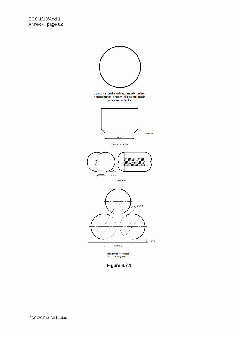
CCC 1/13/Add.1 Annex 4, page 62
I:\CCC\01\13-Add-1.doc
Figure 6.7.1

CCC 1/13/Add.1 Annex 4, page 63
I:\CCC\01\13-Add-1.doc
6.7.3.1.2 For vacuum insulated tanks in hold spaces and for tanks in hold spaces separated from potential fire loads by coffer dams or surrounded by ship spaces with no fire load the following applies:
If the pressure relief valves have to be sized for fire loads the fire factors according may be reduced to the following values: F=0.5 to F=0.25 F=0.2 to F=0.1 The minimum fire factor is F=0.1
6.7.3.1.3 The required mass flow of air at relieving conditions is given by: Mair = Q * ρair (kg/s) where density of air (ρair) = 1.293 kg/m3 (air at 273.15 K, 0.1013 MPa). 6.7.3.2 Sizing of vent pipe system 6.7.3.2.1 Pressure losses upstream and downstream of the PRVs, shall be taken into account when determining their size to ensure the flow capacity required by 6.7.3.1. 6.7.3.2.2 Upstream pressure losses
.1 The pressure drop in the vent line from the tank to the PRV inlet shall not exceed 3% of the valve set pressure at the calculated flow rate, in accordance with 6.7.3.1.
.2 Pilot-operated PRVs shall be unaffected by inlet pipe pressure losses when the pilot senses directly from the tank dome.
.3 Pressure losses in remotely sensed pilot lines shall be considered for flowing type pilots.
6.7.3.2.3 Downstream pressure losses
.1 Where common vent headers and vent masts are fitted, calculations shall include flow from all attached PRVs.
.2 The built-up back pressure in the vent piping from the PRV outlet to the
location of discharge to the atmosphere, and including any vent pipe interconnections that join other tanks, shall not exceed the following values:
.1 for unbalanced PRVs: 10% of MARVS;
.2 for balanced PRVs: 30% of MARVS; and
.3 for pilot operated PRVs: 50% of MARVS.
Alternative values provided by the PRV manufacturer may be accepted.
6.7.3.2.4 To ensure stable PRV operation, the blow-down shall not be less than the sum of the inlet pressure loss and 0.02 MARVS at the rated capacity.

CCC 1/13/Add.1 Annex 4, page 64
I:\CCC\01\13-Add-1.doc
6.8 Regulations on filling limit for liquefied gas fuel tanks 6.8.1 Storage tanks for liquefied gas shall not be filled to more than 98% full at the reference temperature, where the reference temperature means the temperature corresponding to the vapour pressure of the fuel at the set pressure of the pressure relief valves. A filling limit curve for actual fuel filling temperatures shall be prepared from the following formula:
LL = FL ρR/ρL
where:
LL = loading limit, maximum allowable liquid volume relative to the tank volume to which the tank may be loaded, expressed in per cent;
FL = filling limit expressed in per cent, here 98%;
ρR = relative density of fuel at the reference temperature; and
ρL = relative density of fuel at the loading temperature. 6.8.2 However, in cases where the tank insulation and tank location make the probability very small for the tank contents to be heated up due to external fire, special considerations may be made to allow a higher filling limit than calculated using the reference temperature, but never above 95%. This will be also be valid in case a second system for pressure maintenance is installed, refer to 6.9. However, if the pressure can only be maintained/ controlled by fuel consumers, the filling limit as calculated in 6.8.1 should be used.
6.9 Regulations for the maintaining of fuel storage condition
6.9.1 Control of tank pressure and temperature
6.9.1.1 With the exception of liquefied gas fuel tanks designed to withstand the full gauge vapour pressure of the fuel under conditions of the upper ambient design temperature, fuel tanks' pressure and temperature shall be maintained at all times within their design range by means acceptable to the Administration or its recognized organization acting on its behalf, e.g. by one of the following methods:
.1 reliquefaction of vapours;
.2 thermal oxidation of vapours; .3 pressure accumulation; and .4 liquefied gas fuel cooling.
The method chosen shall be capable of maintaining tank pressure below the set pressure of the tank for a period of 15 days assuming full tank at normal service pressure and the ship in idle condition, i.e. only power for domestic load is generated. 6.9.1.2 Venting of fuel vapour for control of the tank pressure is not acceptable except in emergency situations.

CCC 1/13/Add.1 Annex 4, page 65
I:\CCC\01\13-Add-1.doc
6.9.2 Design of systems 6.9.2.1 For worldwide service, the upper ambient design temperature shall be sea 32oC and air 45oC. For service in particularly hot or cold zones, these design temperatures shall be increased or decreased, as appropriate. 6.9.2.2 The overall capacity of the system shall be such that it can control the pressure within the design conditions without venting to atmosphere. 6.9.3 Reliquefaction systems
6.9.3.1 The reliquefaction system shall be designed and calculated according to 6.9.3.2. The system has to be sized in a sufficient way also in case of no or low consumption.
6.9.3.2 The reliquefaction system shall be arranged in one of the following ways:
.1 a direct system where evaporated fuel is compressed, condensed and returned to fuel tanks;
.2 an indirect system where fuel or evaporated fuel is cooled or condensed by
refrigerant without being compressed; .3 a combined system where evaporated fuel is compressed and condensed
in a fuel/refrigerant heat exchanger and returned to the fuel tanks; .4 if the reliquefaction system produces a waste stream containing methane
during pressure control operations within the design conditions, these waste gases shall, as far as reasonably practicable, be disposed of without venting to atmosphere.
6.9.4 Thermal oxidation systems 6.9.4.1 Thermal oxidation can be done by either consumption of the vapours according to the regulations for consumers described in this Code or in a dedicated gas combustion unit (GCU). It has to be demonstrated that the capacity of the oxidation system is sufficient to consume the required quantity of vapours. In this regard periods of slow steaming and/or no consumption from propulsion or other services of the vessel has to be considered. 6.9.5 Compatibility 6.9.5.1 Refrigerants or auxiliary agents used for refrigeration or cooling of fuel must be compatible with the fuel they may come in contact with (not causing any hazardous reaction or excessively corrosive products). In addition, when several refrigerants or agents are used, these must be compatible with each other. 6.9.6 Availability of systems 6.9.6.1 The availability of the system and its supporting auxiliary services shall be such that in case of a single failure (of mechanical non-static component or a component of the control systems) the fuel tank pressure and temperature can be maintained by another service/system. 6.9.6.2 Heat exchangers that are solely necessary for maintaining the pressure and temperature of the fuel tanks within their design ranges shall have a standby heat exchanger
CCC 1/13/Add.1 Annex 4, page 66
I:\CCC\01\13-Add-1.doc
unless they have a capacity in excess of 25% of the largest required capacity for pressure control and they can be repaired on board without external sources. 6.10 Regulations on atmospheric control within the fuel storage system 6.10.1 A piping system shall be arranged to enable each fuel storage tank to be safely gas-freed, and to be safely filled with fuel from a gas-free condition. The system shall be arranged to minimize the possibility of pockets of gas or air remaining after changing the atmosphere. 6.10.2 The system shall be designed to eliminate the possibility of a flammable mixture existing in the fuel tank during any part of the atmosphere change operation by utilizing an inerting medium as an intermediate step. 6.10.3 Gas sampling points shall be provided for each fuel tank to monitor the progress of atmosphere change. 6.10.4 Inert gas utilized for gas freeing of tanks may be provided externally to the ship.
6.11 Regulations on atmosphere control within hold spaces (Fuel containment
systems other than type C independent tanks)
6.11.1 Interbarrier and hold spaces associated with fuel containment systems requiring full or partial secondary barriers shall be inerted with a suitable dry inert gas and kept inerted with make-up gas provided by a shipboard inert gas generation system, or by shipboard storage, which shall be sufficient for normal consumption for at least 30 days. Shorter periods may be considered by the Administration or its recognized organization acting on its behalf depending on the ship's service. 6.11.2 Alternatively, the spaces referred to in 6.11.1 requiring only a partial secondary barrier may be filled with dry air provided that the ship maintains a stored charge of inert gas or is fitted with an inert gas generation system sufficient to inert the largest of these spaces, and provided that the configuration of the spaces and the relevant vapour detection systems, together with the capability of the inerting arrangements, ensures that any leakage from the fuel tanks will be rapidly detected and inerting effected before a dangerous condition can develop. Equipment for the provision of sufficient dry air of suitable quality to satisfy the expected demand shall be provided. 6.12 Regulations on environmental control of spaces surrounding type C
independent tanks 6.12.1 Spaces surrounding fuel tanks shall be filled with suitable dry air and be maintained in this condition with dry air provided by suitable air drying equipment. This is only applicable for fuel tanks where condensation and icing due to cold surfaces is an issue. 6.13 Regulations on inerting 6.13.1 Arrangements to prevent back-flow of fuel vapour into the inert gas system shall be provided as specified below. 6.13.2 To prevent the return of flammable gas to any non-hazardous spaces, the inert gas supply line shall be fitted with two shutoff valves in series with a venting valve in between (double block and bleed valves). In addition a closable non-return valve shall be installed
CCC 1/13/Add.1 Annex 4, page 67
I:\CCC\01\13-Add-1.doc
between the double block and bleed arrangement and the fuel system. These valves shall be located outside non-hazardous spaces. 6.13.3 Where the connections to the fuel piping systems are non-permanent, two non-return valves may be substituted for the valves required in 6.13.2. 6.13.4 The arrangements shall be such that each space being inerted can be isolated and the necessary controls and relief valves, etc. shall be provided for controlling pressure in these spaces. 6.13.5 Where insulation spaces are continually supplied with an inert gas as part of a leak detection system, means shall be provided to monitor the quantity of gas being supplied to individual spaces. 6.14 Regulations on inert gas production and storage on board 6.14.1 The equipment shall be capable of producing inert gas with oxygen content at no time greater than 5% by volume. A continuous-reading oxygen content meter shall be fitted to the inert gas supply from the equipment and shall be fitted with an alarm set at a maximum of 5% oxygen content by volume. 6.14.2 An inert gas system shall have pressure controls and monitoring arrangements appropriate to the fuel containment system. 6.14.3 Where a nitrogen generator or nitrogen storage facilities are installed in a separate compartment outside of the engine-room, the separate compartment shall be fitted with an independent mechanical extraction ventilation system, providing a minimum of 6 air changes per hour. A low oxygen alarm shall be fitted. 6.14.4 Nitrogen pipes shall only be led through well ventilated spaces. Nitrogen pipes in enclosed spaces shall:
- be fully welded; - have only a minimum of flange connections as needed for fitting of valves; and - be as short as possible.
7 MATERIAL AND GENERAL PIPE DESIGN 7.1 Goal
7.1.1 The goal of this chapter is to ensure the safe handling of fuel, under all operating conditions, to minimize the risk to the ship, personnel and to the environment, having regard to the nature of the products involved. 7.2 Functional requirements 7.2.1 This chapter relates to functional requirements in 3.2.1, 3.2.5, 3.2.6, 3.2.8, 3.2.9 and 3.2.10. In particular the following apply: 7.2.1.1 Fuel piping shall be capable of absorbing thermal expansion or contraction caused by extreme temperatures of the fuel without developing substantial stresses.
CCC 1/13/Add.1 Annex 4, page 68
I:\CCC\01\13-Add-1.doc
7.2.1.2 Provision shall be made to protect the piping, piping system and components and fuel tanks from excessive stresses due to thermal movement and from movements of the tank and hull structure. 7.2.1.3 If the fuel gas contains heavier constituents that may condense in the system, means for safely removing the liquid shall be fitted. 7.2.1.4 Low temperature piping shall be thermally isolated from the adjacent hull structure, where necessary, to prevent the temperature of the hull from falling below the design temperature of the hull material. 7.3 Regulations for general pipe design 7.3.1 General 7.3.1.1 Fuel pipes and all the other piping needed for a safe and reliable operation and maintenance shall be colour marked in accordance with a standard at least equivalent to those acceptable to the Organization.13 7.3.1.2 Where tanks or piping are separated from the ship's structure by thermal isolation, provision shall be made for electrically bonding to the ship's structure both the piping and the tanks. All gasketed pipe joints and hose connections shall be electrically bonded. 7.3.1.3 All pipelines or components which may be isolated in a liquid full condition shall be provided with relief valves. 7.3.1.4 Pipework, which may contain low temperature fuel, shall be thermally insulated to an extent which will minimize condensation of moisture. 7.3.1.5 Piping other than fuel supply piping and cabling may be arranged in the double wall piping or duct provided that they do not create a source of ignition or compromise the integrity of the double pipe or duct. The double wall piping or duct shall only contain piping or cabling necessary for operational purposes. 7.3.2 Wall thickness 7.3.2.1 The minimum wall thickness shall be calculated as follows:
t = (t0 + b + c) / (1 - a/100) (mm)
where:
t0 = theoretical thickness t0 = PD/(20Ke + P) (mm) with:
P = design pressure (bar) referred to in 7.3.3; D = outside diameter (mm);
13 Refer to EN ISO 14726:2008 Ships and marine technology – Identification colours for the content of piping
systems.

CCC 1/13/Add.1 Annex 4, page 69
I:\CCC\01\13-Add-1.doc
K = allowable stress (N/mm²) referred to in 7.3.4; and e = efficiency factory equal to 1.0 for seamless pipes and for
longitudinally or spirally welded pipes, delivered by approved manufacturers of welded pipes, that are considered equivalent to seamless pipes when non-destructive testing on welds is carried out in accordance with recognized standards. In other cases an efficiency factor of less than 1.0, in accordance with recognized standards, may be required depending on the manufacturing process;
b = allowance for bending (mm). The value of b shall be chosen so that the calculated stress in the bend, due to internal pressure only, does not exceed the allowable stress. Where such justification is not given, b shall be:
b = Dt0/2.5r (mm)
with:
r = mean radius of the bend (mm);
c = corrosion allowance (mm). If corrosion or erosion is expected the wall thickness of the piping shall be increased over that required by other design regulations. This allowance shall be consistent with the expected life of the piping; and
a = negative manufacturing tolerance for thickness (%).
7.3.2.2 The absolute minimum wall thickness shall be in accordance with a standard acceptable to the Administration or its recognized organization acting on its behalf.
7.3.3 Design condition
7.3.3.1 The greater of the following design conditions shall be used for piping, piping system and components as appropriate:14,15
.1 for systems or components which may be separated from their relief valves and which contain only vapour at all times, vapour pressure at 45°C assuming an initial condition of saturated vapour in the system at the system operating pressure and temperature; or
.2 the MARVS of the fuel tanks and fuel processing systems; or .3 the pressure setting of the associated pump or compressor discharge relief
valve; or .4 the maximum total discharge or loading head of the fuel piping system; or .5 the relief valve setting on a pipeline system.
14 Lower values of ambient temperature regarding design condition in 7.3.3.1.1 may be accepted by the
Administration or its recognized organization for ships operating in restricted areas. Conversely, higher values of ambient temperature may be required.
15 For ships on voyages of restricted duration, P0 may be calculated based on the actual pressure rise during
the voyage and account may be taken of any thermal insulation of the tank. Reference is made to the Application of amendments to gas carrier codes concerning type C tank loading limits (SIGTTO/IACS).

CCC 1/13/Add.1 Annex 4, page 70
I:\CCC\01\13-Add-1.doc
7.3.3.2 Piping, piping systems and components shall have a minimum design pressure of 10 bar except for open ended lines where it is not to be less than 5 bar.
7.3.4 Allowable stress
7.3.4.1 For pipes made of steel including stainless steel, the allowable stress to be considered in the formula of the strength thickness in 7.3.2.1 shall be the lower of the following values:
Rm/2.7 or Re/1.8 where:
Rm = specified minimum tensile strength at room temperature (N/mm²); and
Re = specified minimum yield stress at room temperature (N/mm²). If the stress strain curve does not show a defined yield stress, the 0.2% proof stress applies.
7.3.4.2 Where necessary for mechanical strength to prevent damage, collapse, excessive sag or buckling of pipes due to superimposed loads, the wall thickness shall be increased over that required by 7.3.2 or, if this is impracticable or would cause excessive local stresses, these loads shall be reduced, protected against or eliminated by other design methods. Such superimposed loads may be due to; supports, ship deflections, liquid pressure surge during transfer operations, the weight of suspended valves, reaction to loading arm connections, or otherwise. 7.3.4.3 For pipes made of materials other than steel, the allowable stress shall be considered by the Administration or its recognized organization acting on its behalf. 7.3.4.4 High pressure fuel piping systems shall have sufficient constructive strength. This shall be confirmed by carrying out stress analysis and taking into account:
.1 stresses due to the weight of the piping system; .2 acceleration loads when significant; and .3 internal pressure and loads induced by hog and sag of the ship.
7.3.4.5 When the design temperature is minus 110°C or colder, a complete stress analysis, taking into account all the stresses due to weight of pipes, including acceleration loads if significant, internal pressure, thermal contraction and loads induced by hog and sag of the ship shall be carried out for each branch of the piping system. 7.3.5 Flexibility of piping 7.3.5.1 The arrangement and installation of fuel piping shall provide the necessary flexibility to maintain the integrity of the piping system in the actual service situations, taking potential for fatigue into account. 7.3.6 Piping fabrication and joining details 7.3.6.1 Flanges, valves and other fittings shall comply with a standard acceptable to the Administration or its recognized organization acting on its behalf, taking into account the design pressure defined in 7.3.3.1. For bellows and expansion joints used in vapour service, a lower minimum design pressure than defined in 7.3.3.1 may be accepted.

CCC 1/13/Add.1 Annex 4, page 71
I:\CCC\01\13-Add-1.doc
7.3.6.2 All valves and expansion joints used in high pressure fuel piping systems shall be approved according to a standard acceptable to the Administration or its recognized organization acting on its behalf. 7.3.6.3 The piping system shall be joined by welding with a minimum of flange connections. Gaskets shall be protected against blow-out. 7.3.6.4 Piping fabrication and joining details shall comply with the following: 7.3.6.4.1 Direct connections
.1 Butt-welded joints with complete penetration at the root may be used in all applications. For design temperatures colder than -10°C, butt welds shall be either double welded or equivalent to a double welded butt joint. This may be accomplished by use of a backing ring, consumable insert or inert gas back-up on the first pass. For design pressures in excess of 10 bar and design temperatures of minus 10°C or colder, backing rings shall be removed.
.2 Slip-on welded joints with sleeves and related welding, having dimensions
in accordance with recognized standards, shall only be used for instrument lines and open-ended lines with an external diameter of 50 mm or less and design temperatures not colder than minus 55°C.
.3 Screwed couplings complying with recognized standards shall only be used
for accessory lines and instrumentation lines with external diameters of 25 mm or less.
7.3.6.4.2 Flanged connections
.1 Flanges in flange connections shall be of the welded neck, slip-on or socket welded type.
.2 For all piping except open ended, the following restrictions apply:
For design temperatures colder than minus 55°C, only welded neck flanges shall be used.
.3 For design temperatures colder than minus 10°C, slip-on flanges shall not
be used in nominal sizes above 100 mm and socket welded flanges shall not be used in nominal sizes above 50 mm.
7.3.6.4.3 Expansion joints Where bellows and expansion joints are provided in accordance with 7.3.6.1 the following apply:
.1 If necessary, bellows shall be protected against icing. .2 Slip joints shall not be used except within the liquefied gas fuel storage
tanks. .3 Bellows shall normally not be arranged in enclosed spaces.

CCC 1/13/Add.1 Annex 4, page 72
I:\CCC\01\13-Add-1.doc
7.3.6.4.4 Other connections Piping connections shall be joined in accordance with 7.3.6.4.1 to 7.3.6.4.3 but for other exceptional cases the Administration or its recognized organization acting on its behalf may consider alternative arrangements. 7.4 Regulations for materials 7.4.1 Metallic materials 7.4.1.1 Materials for fuel containment and piping systems shall comply with the minimum regulations given in the following tables:
Table 7.1: Plates, pipes (seamless and welded), sections and forgings for fuel tanks and process pressure vessels for design temperatures not lower than 0°C. Table 7.2: Plates, sections and forgings for fuel tanks, secondary barriers and process pressure vessels for design temperatures below 0°C and down to minus 55°C. Table 7.3: Plates, sections and forgings for fuel tanks, secondary barriers and process pressure vessels for design temperatures below -55°C and down to minus 165°C. Table 7.4: Pipes (seamless and welded), forgings and castings for fuel and process piping for design temperatures below 0°C and down to minus 165°C. Table 7.5: Plates and sections for hull structures required by 6.4.13.1.1.2.

CCC 1/13/Add.1 Annex 4, page 73
I:\CCC\01\13-Add-1.doc
Table 7.1
PLATES, PIPES (SEAMLESS AND WELDED) 1, 2, SECTIONS AND FORGINGS FOR FUEL TANKS AND PROCESS PRESSURE VESSELS FOR DESIGN
TEMPERATURES NOT LOWER THAN 0°C
CHEMICAL COMPOSITION AND HEAT TREATMENT
Carbon-manganese steel
Fully killed fine grain steel
Small additions of alloying elements by agreement with the Administration
Composition limits to be approved by the Administration
Normalized, or quenched and tempered4
TENSILE AND TOUGHNESS (IMPACT) TEST REGULATIONS
Sampling frequency
Plates Each "piece" to be tested
Sections and forgings Each "batch" to be tested.
Mechanical properties
Tensile properties Specified minimum yield stress not to exceed 410 N/mm2 5
Toughness (Charpy V-notch test)
Plates Transverse test pieces. Minimum average energy value (KV) 27J
Sections and forgings Longitudinal test pieces. Minimum average energy (KV) 41J
Test temperature
Thickness t (mm) Test temperature
(°C)
t<20 0
20<t <403 -20
Notes 1. For seamless pipes and fittings normal practice applies. The use of longitudinally and spirally
welded pipes shall be specially approved by the Administration or its recognized organization acting on its behalf.
2. Charpy V-notch impact tests are not required for pipes. 3. This Table is generally applicable for material thicknesses up to 40 mm. Proposals for greater
thicknesses shall be approved by the Administration or its recognized organization acting on its behalf.
4. A controlled rolling procedure or TMCP may be used as an alternative. 5. Materials with specified minimum yield stress exceeding 410 N/mm2 may be approved by the
Administration or its recognized organization acting on its behalf. For these materials, particular attention should be given to the hardness of the welded and heat affected zones.

CCC 1/13/Add.1 Annex 4, page 74
I:\CCC\01\13-Add-1.doc
Table 7.2
PLATES, SECTIONS AND FORGINGS 1 FOR FUEL TANKS, SECONDARY BARRIERS AND PROCESS PRESSURE VESSELS FOR DESIGN TEMPERATURES BELOW 0°C AND DOWN
TO - 55°C Maximum thickness 25 mm 2
CHEMICAL COMPOSITION AND HEAT TREATMENT
Carbon-manganese steel
Fully killed, aluminium treated fine grain steel
Chemical composition (ladle analysis)
C Mn Si S P
0.16% max. 3 0.70-1.60% 0.10-0.50% 0.025% max. 0.025% max.
Optional additions: Alloys and grain refining elements may be generally in accordance with the following
Ni Cr Mo Cu Nb
0.80% max. 0.25% max. 0.08% max. 0.35% max. 0.05% max.
V
0.10% max.
Al content total 0.020% min. (Acid soluble 0.015% min.)
Normalized, or quenched and tempered 4
TENSILE AND TOUGHNESS (IMPACT) TEST REGULATIONS
Sampling frequency
Plates Each 'piece' to be tested
Sections and forgings Each 'batch' to be tested
Mechanical properties
Tensile properties Specified minimum yield stress not to exceed 410 N/mm2, 5
Toughness (Charpy V-notch test)
Plates Transverse test pieces. Minimum average energy value (KV) 27J
Sections and forgings Longitudinal test pieces. Minimum average energy (KV) 41J
Test temperature 5°C below the design temperature or -20°C whichever is lower Notes 1. The Charpy V-notch and chemistry regulations for forgings may be specially considered by
the Administration. 2. For material thickness of more than 25 mm, Charpy V-notch tests shall be conducted as follows:
Material thickness (mm) Test temperature (°C)
25 < t ≤ 30 10°C below design temperature or -20°C whichever is lower
30 < t ≤ 35 15°C below design temperature or -20°C whichever is lower
35 < t ≤ 40 20°C below design temperature
40 < t Temperature approved by the Administration or its recognized organization acting on its behalf
The impact energy value shall be in accordance with the table for the applicable type of test specimen. Materials for tanks and parts of tanks which are completely thermally stress relieved after welding may be tested at a temperature 5°C below design temperature or -20°C whichever is lower. For thermally stress relieved reinforcements and other fittings, the test temperature shall be the same as that required for the adjacent tank-shell thickness.
3. By special agreement with the Administration, the carbon content may be increased to 0,18% maximum provided the design temperature is not lower than -40°C
4. A controlled rolling procedure or TMCP may be used as an alternative. 5. Materials with specified minimum yield stress exceeding 410 N/mm2 may be approved by
the Administration or its recognized organization acting on its behalf. For these materials, particular attention should be given to the hardness of the welded and heat affected zones.
Guidance: For materials exceeding 25 mm in thickness for which the test temperature is -60°C or lower, the application of specially treated steels or steels in accordance with table 7.3 may be necessary.

CCC 1/13/Add.1 Annex 4, page 75
I:\CCC\01\13-Add-1.doc
Table 7.3
PLATES, SECTIONS AND FORGINGS 1 FOR FUEL TANKS, SECONDARY BARRIERS AND PROCESS PRESSURE VESSELS FOR DESIGN TEMPERATURES BELOW -55°C AND
DOWN TO -165°C2 Maximum thickness 25 mm 3, 4
Minimum design temp. (°C)
Chemical composition5 and heat treatment Impact test temp. (°C)
-60 1,5% nickel steel – normalized or normalized and tempered or quenched and tempered or TMCP see note 6
-65
-65 2,25% nickel steel – normalized or normalized and tempered or quenched and tempered or TMCP6, 7
-70
-90 3,5% nickel steel – normalized or normalized and tempered or quenched and tempered or TMCP6, 7
-95
-105 5% nickel steel – normalized or normalized and tempered or quenched and tempered6, 7 and 8
-110
-165 9% nickel steel – double normalized and tempered or quenched and tempered6
-196
-165 Austenitic steels, such as types 304, 304L, 316, 316L, 321 and 347 solution treated9
-196
-165 Aluminium alloys; such as type 5083 annealed Not
required
-165 Austenitic Fe-Ni alloy (36% nickel) Heat treatment as agreed Not
required
TENSILE AND TOUGHNESS (IMPACT) TEST REGULATIONS
Sampling frequency
Plates Each 'piece' to be tested
Sections and forgings Each 'batch' to be tested
Toughness (Charpy V-notch test)
Plates Transverse test pieces. Minimum average energy value (KV) 27J
Sections and forgings Longitudinal test pieces. Minimum average energy (KV) 41J Notes 1. The impact test required for forgings used in critical applications shall be subject to special consideration by
the Administration. 2. The regulations for design temperatures below –165°C shall be specially agreed with
the Administration. 3. For materials 1,5% Ni, 2.25% Ni, 3.5% Ni and 5% Ni, with thicknesses greater than 25 mm,
the impact tests shall be conducted as follows:
Material thickness (mm) Test temperature (°C)
25 < t ≤ 30 10°C below design temperature
30 < t ≤ 35 15°C below design temperature
35 < t ≤ 40 20°C below design temperature
The energy value shall be in accordance with the table for the applicable type of test specimen. For material thickness of more than 40 mm, the Charpy V-notch values shall be specially considered.
4. For 9% Ni steels, austenitic stainless steels and aluminium alloys, thickness greater than 25 mm may be used.
5. The chemical composition limits shall be in accordance with Recognized Standards. 6. TMCP nickel steels will be subject to acceptance by the Administration. 7. A lower minimum design temperature for quenched and tempered steels may be specially agreed with the
Administration. 8. A specially heat treated 5% nickel steel, for example triple heat treated 5% nickel steel, may be used down
to –165°C, provided that the impact tests are carried out at –196°C. 9. The impact test may be omitted subject to agreement with the Administration.

CCC 1/13/Add.1 Annex 4, page 76
I:\CCC\01\13-Add-1.doc
Table 7.4
PIPES (SEAMLESS AND WELDED)1, FORGINGS2 AND CASTINGS2 FOR FUEL AND PROCESS PIPING FOR DESIGN
TEMPERATURES BELOW 0°C AND DOWN TO -165°C3 Maximum thickness 25 mm
Minimum design
temp.(°C) Chemical composition5 and heat treatment
Impact test
Test temp. (°C)
Minimum average energy (KV)
-55 Carbon-manganese steel. Fully killed fine grain. Normalized or as agreed.6
See note 4 27
-65 2.25% nickel steel. Normalized, Normalized and tempered or quenched and tempered.6
-70 34
-90 3.5% nickel steel. Normalized, Normalized and tempered or quenched and tempered.6
-95 34
-165
9% nickel steel7. Double normalized and tempered or quenched and tempered.
-196 41
Austenitic steels, such as types 304, 304L, 316, 316L, 321 and 347. Solution treated.8
-196 41
Aluminium alloys; such as type 5083 annealed Not
required TENSILE AND TOUGHNESS (IMPACT) TEST REGULATIONS
Sampling frequency Each 'batch' to be tested.
Toughness (Charpy V-notch test) Impact test: Longitudinal test pieces Notes
1. The use of longitudinally or spirally welded pipes shall be specially approved by the Administration.
2. The regulations for forgings and castings may be subject to special consideration by
the Administration.
3. The regulations for design temperatures below -165°C shall be specially agreed with
the Administration.
4. The test temperature shall be 5°C below the design temperature or -20°C whichever is lower.
5. The composition limits shall be in accordance with Recognized Standards.
6. A lower design temperature may be specially agreed with the Administration for quenched and tempered
materials.
7. This chemical composition is not suitable for castings.
8. Impact tests may be omitted subject to agreement with the Administration.
Table 7.5 PLATES AND SECTIONS FOR HULL STRUCTURES REQUIRED BY 6.4.13.1.1.2
Minimum design temperature of hull
structure (°C)
Maximum thickness (mm) for steel grades
A B D E AH DH EH FH
0 and above Recognized Standards
down to -5 15 25 30 50 25 45 50 50
down to -10 x 20 25 50 20 40 50 50
down to -20 x x 20 50 x 30 50 50
down to -30 x x x 40 x 20 40 50
Below -30 In accordance with table 7.2 except that the thickness limitation given in table 7.2 and in footnote 2 of that table does not apply.
Notes 'x' means steel grade not to be used.

CCC 1/13/Add.1 Annex 4, page 77
I:\CCC\01\13-Add-1.doc
7.4.1.2 Material having a melting point below 925°C should not be used for piping outside the gas tanks. 7.4.1.3 For CNG tanks, the use of materials not covered above may be specially considered by the Administration or its recognized organization acting on its behalf. 7.4.1.4 Where required the outer pipe or duct containing high pressure gas in the inner pipe shall as a minimum fulfil the material regulations for pipe materials with design temperature down to minus 55°C in table 7.4. 7.4.1.5 The outer pipe or duct around liquefied gas fuel pipes shall as a minimum fulfil the material regulations for pipe materials with design temperature down to minus 165°C in table 7.4. 8 BUNKERING 8.1 Goal 8.1.1 The goal of this chapter is to provide for suitable systems on board the ship to ensure that bunkering can be conducted without causing danger to persons, the environment or the ship. 8.2 Functional requirements 8.2.1 This chapter relates to functional requirements in 3.2.1 to 3.2.11 and 3.2.13 to 3.2.17. In particular the following apply: 8.2.1.1 The piping system for transfer of fuel to the storage tank shall be designed such that any leakage from the piping system cannot cause danger to personnel, the environment or the ship. 8.3 Regulations for bunkering station 8.3.1 General 8.3.1.1 The bunkering station shall be located on open deck so that sufficient natural ventilation is provided. Closed or semi-enclosed bunkering stations shall be subject to special consideration within the risk assessment. 8.3.1.3 Connections and piping shall be so positioned and arranged that any damage to the fuel piping does not cause damage to the ship's fuel containment system resulting in an uncontrolled gas discharge. 8.3.1.5 Arrangements shall be made for safe management of any spilled fuel. 8.3.1.6 Suitable means should be provided to relieve the pressure and remove liquid contents from pump suctions and bunker lines. Liquid is to be discharged to the fuel tanks or other suitable location. 8.3.1.7 The surrounding hull or deck structures shall not be exposed to unacceptable cooling, in case of leakage of fuel. 8.3.1.8 For compressed gas bunkering stations, low temperature steel shielding shall be considered to determine if the escape of cold jets impinging on surrounding hull structure is possible.
CCC 1/13/Add.1 Annex 4, page 78
I:\CCC\01\13-Add-1.doc
8.3.2 Ships' fuel hoses 8.3.2.1 Liquid and vapour hoses used for fuel transfer shall be compatible with the fuel and suitable for the fuel temperature. 8.3.2.2 Hoses subject to tank pressure, or the discharge pressure of pumps or vapour compressors, shall be designed for a bursting pressure not less than five times the maximum pressure the hose can be subjected to during bunkering. 8.4 Regulations for manifold
8.4.1 The bunkering manifold shall be designed to withstand the external loads during bunkering. The connections at the bunkering station shall be of dry-disconnect type equipped with additional safety dry break-away coupling/ self-sealing quick release. The couplings shall be of a standard type.
8.5 Regulations for bunkering system
8.5.1 An arrangement for purging fuel bunkering lines with inert gas shall be provided.
8.5.2 The bunkering system shall be so arranged that no gas is discharged to the atmosphere during filling of storage tanks.
8.5.3 A manually operated stop valve and a remote operated shutdown valve in series, or a combined manually operated and remote valve shall be fitted in every bunkering line close to the connecting point. It shall be possible to operate the remote valve in the control location for bunkering operations and/or from another safe location.
8.5.4 Means shall be provided for draining any fuel from the bunkering pipes upon completion of operation.
8.5.5 Bunkering lines shall be arranged for inerting and gas freeing. When not engaged in bunkering, the bunkering pipes shall be free of gas, unless the consequences of not gas freeing is evaluated and approved.
8.5.6 In case bunkering lines are arranged with a cross-over it shall be ensured by suitable isolation arrangements that no fuel is transferred inadvertently to the ship side not in use for bunkering.
8.5.7 A ship-shore link (SSL) or an equivalent means for automatic and manual ESD communication to the bunkering source shall be fitted.
8.5.8 If not demonstrated to be required at a higher value due to pressure surge considerations a default time as calculated in accordance with 16.7.3.7 from the trigger of the alarm to full closure of the remote operated valve required by 8.5.3 shall be adjusted.
9 FUEL SUPPLY TO CONSUMERS
9.1 Goal
The goal of this chapter is to ensure safe and reliable distribution of fuel to the consumers.

CCC 1/13/Add.1 Annex 4, page 79
I:\CCC\01\13-Add-1.doc
9.2 Functional requirements
This chapter is related to functional requirements in 3.2.1 to 3.2.6, 3.2.8 to 3.2.11 and 3.2.13 to 3.2.17. In particular the following apply: .1 The fuel supply system shall be so arranged that the consequences of any
release of fuel will be minimized, while providing safe access for operation and inspection.
.2 The piping system for fuel transfer to the consumers shall be designed in a
way that a failure of one barrier cannot lead to a leak from the piping system into the surrounding area causing danger to the persons on board, the environment or the ship.
.3 Fuel lines outside the machinery spaces shall be installed and protected so
as to minimize the risk of injury to personnel in case of leakage. 9.3 Regulations on redundancy of fuel supply 9.3.1 For single fuel installations the fuel supply system shall be arranged with full redundancy and segregation all the way from the fuel tanks to the consumer, so that a leakage in one system does not lead to an unacceptable loss of power. 9.3.2 For single fuel installations (gas only), the fuel storage should be divided between two or more tanks. The tanks should be located in separate compartments. 9.3.3 For type C tank only, one tank may be accepted if two completely separate tank connection spaces are installed for the one tank. 9.4 Regulations on safety functions of gas supply system 9.4.1 Fuel storage tank inlets and outlets shall be provided with valves located as close to the tank as possible. Valves required to be operated during normal operation16 which are not accessible shall be remotely operated. Tank valves whether accessible or not shall be automatically operated when the safety system required in 15.2.2 is activated. 9.4.2 The main gas supply line to each gas consumer or set of consumers shall be equipped with a manually operated stop valve and an automatically operated "master gas fuel valve" coupled in series or a combined manually and automatically operated valve. The valves shall be situated in the part of the piping that is outside the machinery space containing gas consumers, and placed as near as possible to the installation for heating the gas, if fitted. The master gas fuel valve shall automatically cut off the gas supply when activated by the safety system required in 15.2.2. 9.4.3 The automatic master gas fuel valve shall be operable from safe locations on escape routes inside a machinery space containing a gas consumer, the engine control room, if applicable; outside the machinery space, and from the navigation bridge. 9.4.4 Each gas consumer shall be provided with "double block and bleed" valves arrangement. These valves shall be arranged as outlined in .1 or .2 so that when the safety system required in 15.2.2 is activated this will cause the shut off valves that are in series to close automatically and the bleed valve to open automatically and:
16 Normal operation in this context is when gas is supplied to consumers and during bunkering operations.

CCC 1/13/Add.1 Annex 4, page 80
I:\CCC\01\13-Add-1.doc
.1 the two shut-off valves shall be in series in the gas fuel pipe to the gas consuming equipment. The bleed valve shall be in a pipe that vents to a safe location in the open air that portion of the gas fuel piping that is between the two valves in series; or
.2 the function of one of the shut off valves in series and the bleed valve can
be incorporated into one valve body, so arranged that the flow to the gas utilization unit will be blocked and the ventilation opened.
9.4.5 The two valves shall be of the fail-to-close type, while the ventilation valve shall be fail-to-open. 9.4.6 The double block and bleed valves shall also be used for normal stop of the engine. 9.4.7 In cases where the master gas fuel valve is automatically shut-down, the complete gas supply branch downstream of the double block and bleed valve shall be automatically ventilated assuming reverse flow from the engine to the pipe. 9.4.8 There shall be one manually operated shutdown valve in the gas supply line to each engine upstream of the double block and bleed valves to assure safe isolation during maintenance on the engine. 9.4.9 For single-engine installations and multi-engine installations, where a separate master valve is provided for each engine, the master gas fuel valve and the double block and bleed valve functions can be combined. 9.4.10 For each main gas supply line entering an ESD protected machinery space, and each gas supply line to high pressure installations means shall be provided for rapid detection of a rupture in the gas line in the engine-room. When rupture is detected a valve shall be automatically shut off.17 This valve shall be located in the gas supply line before it enters the engine-room or as close as possible to the point of entry inside the engine-room. It can be a separate valve or combined with other functions, e.g. the master valve. 9.5 Regulations for fuel distribution outside of machinery space 9.5.1 Where fuel pipes pass through enclosed spaces in the ship, they shall be protected by a secondary enclosure. This enclosure can be a ventilated duct or a double wall piping system. The duct or double wall piping system shall be mechanically under pressure ventilated with 30 air changes per hour, and gas detection as required in 15.8 shall be provided. Other solutions providing an equivalent safety level may also be accepted by the Administration.
9.6 Regulations for fuel supply to consumers in gas-safe machinery spaces
9.6.1 Fuel piping in gas-safe machinery spaces shall be completely enclosed by a double pipe or duct fulfilling one of the following conditions:
.1 The gas piping should be a double wall piping system with the gas fuel
contained in the inner pipe. The space between the concentric pipes should be pressurized with inert gas at a pressure greater than the gas fuel pressure. Suitable alarms should be provided to indicate a loss of inert gas
17 The shutdown shall be time delayed to prevent shutdown due to transient load variations.

CCC 1/13/Add.1 Annex 4, page 81
I:\CCC\01\13-Add-1.doc
pressure between the pipes. When the inner pipe contains high pressure gas, the system should be so arranged that the pipe between the master gas valve and the engine is automatically purged with inert gas when the master gas valve is closed; or
.2 The gas fuel piping should be installed within a ventilated pipe or duct. The
air space between the gas fuel piping and the wall of the outer pipe or duct should be equipped with mechanical under pressure ventilation having a capacity of at least 30 air changes per hour. This ventilation capacity may be reduced to 10 air changes per hour provided automatic filling of the duct with nitrogen upon detection of gas is arranged for. The fan motors should comply with the required explosion protection in the installation area. The ventilation outlet should be covered by a protection screen and placed in a position where no flammable gas-air mixture may be ignited; or
.3 Other solutions providing an equivalent safety level may also be accepted by the Administration.
9.6.2 The connecting of gas piping and ducting to the gas injection valves shall be completely covered by the ducting. The arrangement shall facilitate replacement and/or overhaul of injection valves and cylinder covers. The double ducting is also required for all gas pipes on the engine itself, until gas is injected into the chamber.18 9.7 Regulations for gas fuel supply to consumers in ESD-protected machinery
spaces 9.7.1 The pressure in the gas fuel supply system shall not exceed 10 bar. 9.7.2 The gas fuel supply lines shall have a design pressure not less than 10 bar. 9.8 Regulations for the design of ventilated duct, outer pipe against inner pipe
gas leakage
9.8.1 The design pressure of the outer pipe or duct of fuel systems shall not be less than the maximum working pressure of the inner pipe. Alternatively for fuel piping systems with a working pressure greater than 10 bar, the design pressure of the outer duct shall not be less than the maximum built-up pressure arising in the annular space considering the local instantaneous peak pressure in way of any rupture and the ventilation arrangements. 9.8.2 For high-pressure fuel piping the design pressure of the ducting shall be taken as the higher of the following:
.1 the maximum built-up pressure: static pressure in way of the rupture
resulting from the gas flowing in the annular space;
.2 local instantaneous peak pressure in way of the rupture: this pressure shall
be taken as the critical pressure given by the following expression:
p = p0
18 If gas is supplied into the air inlet on a low pressure engine, double ducting may be omitted on the air inlet
pipe on the condition that a gas detector is fitted above the engine.

CCC 1/13/Add.1 Annex 4, page 82
I:\CCC\01\13-Add-1.doc
where:
p0 = maximum working pressure of the inner pipe
k = Cp/Cv constant pressure specific heat divided by the constant volume specific heat
k = 1.31 for CH4 The tangential membrane stress of a straight pipe should not exceed the tensile strength divided by 1.5 (Rm/1.5) when subjected to the above pressures. The pressure ratings of all other piping components should reflect the same level of strength as straight pipes. As an alternative to using the peak pressure from the above formula, the peak pressure found from representative tests can be used. Test reports should then be submitted. 9.8.3 Verification of the strength shall be based on calculations demonstrating the duct or pipe integrity. As an alternative to calculations, the strength can be verified by representative tests. 9.8.4 For low pressure fuel piping the duct shall be dimensioned for a design pressure not less than the maximum working pressure of the fuel pipes. The duct shall be pressure tested to show that it can withstand the expected maximum pressure at fuel pipe rupture. 9.9 Regulations for compressors and pumps 9.9.1 If compressors or pumps are driven by shafting passing through a bulkhead or deck, the bulkhead penetration shall be of gastight type. 9.9.2 Compressors and pumps shall be suitable for their intended purpose. All equipment and machinery shall be such as to be adequately tested to ensure suitability for use within a marine environment. Such items to be considered would include, but not be limited to:
.1 environmental; .2 shipboard vibrations and accelerations; .3 effects of pitch, heave and roll motions, etc.; and .4 gas composition.
9.9.3 Arrangements shall be made to ensure that under no circumstances liquefied gas can be introduced in the gas control section or gas-fuelled machinery, unless the machinery is designed to operate with gas in liquid state. 9.9.4 Compressors and pumps shall be fitted with accessories and instrumentation necessary for efficient and reliable function.
CCC 1/13/Add.1 Annex 4, page 83
I:\CCC\01\13-Add-1.doc
10 POWER GENERATION INCLUDING PROPULSION AND OTHER GAS
CONSUMERS
10.1 Goal
10.1.1 The goal of this chapter is to provide safe and reliable delivery of mechanical, electrical or thermal energy.
10.2 Functional requirements This chapter is related to functional requirements in 3.2.1, 3.2.11, 3.2.13, 3.2.16 and 3.2.17. In particular the following apply:
.1 The exhaust systems shall be configured to prevent any accumulation of un-burnt gaseous fuel.
.2 Unless designed with the strength to withstand the worst case over
pressure due to ignited gas leaks, engine components or systems containing or likely to contain an ignitable gas and air mixture shall be fitted with suitable pressure relief systems. Dependent on the particular engine design this may include the air inlet manifolds and scavenge spaces.
.3 The explosion venting shall be led away from where personnel may
normally be present.
.4 All gas consumers shall have a separate exhaust system. 10.3 Regulations for internal combustion engines of Piston type 10.3.1 General 10.3.1.1 The exhaust system shall be equipped with explosion relief ventilation sufficiently dimensioned to prevent excessive explosion pressures in the event of ignition failure of one cylinder followed by ignition of the unburned gas in the system.
10.3.1.2 For engines where the space below the piston is in direct communication with the crankcase a detailed evaluation regarding the hazard potential of fuel gas accumulation in the crankcase is to be carried out and reflected in the safety concept of the engine.
10.3.1.4 Each engine other than two-stroke crosshead diesel engines shall be fitted with vent systems independent of other engines for crankcases and sumps. 10.3.1.5 Where gas can leak directly into the auxiliary system medium (lubricating oil, cooling water), an appropriate means shall be fitted after the engine outlet to extract gas in order to prevent gas dispersion. The gas extracted from auxiliary systems media shall be vented to a safe location in the atmosphere.
10.3.1.6 For engines fitted with ignition systems, prior to admission of gas fuel, correct operation of the ignition system on each unit shall be verified. 10.3.1.7 A means shall be provided to monitor and detect poor combustion or mis-firing. In the event that it is detected, gas operation may be allowed provided that the gas supply to the concerned cylinder is shut-off and provided that the operation of the engine with one cylinder cut-off is acceptable with respects to torsional vibrations.

CCC 1/13/Add.1 Annex 4, page 84
I:\CCC\01\13-Add-1.doc
10.3.1.8 For engines starting on fuels covered by this Code, if combustion has not been detected by the engine monitoring system within an engine specific time after the opening of the fuel supply valve, the fuel supply valve shall be automatically shut off. Means to ensure that any un-burnt fuel mixture is purged away from the exhaust system shall be provided. 10.3.2 Regulations for dual fuel engines 10.3.2.1 In case of shut-off of the gas fuel supply, the engines shall be capable of continuous operation by oil fuel only without interruption. 10.3.2.2 An automatic system shall be fitted to change over from gas fuel operation to oil fuel operation and vice versa with minimum fluctuation of the engine power. Acceptable reliability shall be demonstrated through testing. In the case of unstable operation on engines when gas firing, the engine shall automatically change to oil fuel mode. Manual activation of gas system shut down shall always be possible. 10.3.2.3 In case of a normal stop or an emergency shutdown, the gas fuel supply shall be shut off not later than the ignition source. It shall not be possible to shut off the ignition source without first or simultaneously closing the gas supply to each cylinder or to the complete engine. 10.3.3 Regulations for gas-only engines In case of a normal stop or an emergency shutdown, the gas fuel supply shall be shut off not later than the ignition source. It shall not be possible to shut off the ignition source without first or simultaneously closing the gas supply to each cylinder or to the complete engine. 10.3.4 Regulations for multi-fuel engines 10.3.4.1 In case of shut-off of one fuel supply, the engines shall be capable of continuous operation by an alternative fuel with minimum fluctuation of the engine power. 10.3.4.2 An automatic system shall be fitted to change over from one fuel operation to an alternative fuel operation with minimum fluctuation of the engine power. Acceptable reliability shall be demonstrated through testing. In the case of unstable operation on an engine when using a particular fuel, the engine shall automatically change to an alternative fuel mode. Manual activation shall always be possible. 10.4 Regulations for main and auxiliary boilers 10.4.1 Each boiler shall have a dedicated forced draught system. A crossover between boiler force draught systems may be fitted for emergency use providing that any relevant safety functions are maintained. 10.4.2 Combustion chambers and uptakes of boilers shall be designed to prevent any accumulation of gaseous fuel.
GAS ONLY DUAL FUEL MULTI FUEL
IGNITION MEDIUM
Spark Pilot fuel Pilot fuel N/A
MAIN FUEL
Gas Gas Gas and/ or Oil fuel
Gas and/ or Liquid

CCC 1/13/Add.1 Annex 4, page 85
I:\CCC\01\13-Add-1.doc
10.4.3 Burners shall be designed to maintain stable combustion under all firing conditions. 10.4.4 On main/propulsion boilers an automatic system shall be provided to change from gas fuel operation to oil fuel operation without interruption of boiler firing. 10.4.5 Gas nozzles and the burner control system shall be configured such that gas fuel can only be ignited by an established oil fuel flame, unless the boiler and combustion equipment is designed and approved by the Administration or its recognized organization acting on its behalf to light on gas fuel. 10.4.6 There shall be arrangements to ensure that gas fuel flow to the burner is automatically cut off unless satisfactory ignition has been established and maintained. 10.4.7 On the fuel pipe of each gas burner a manually operated shut-off valve shall be fitted. 10.4.8 Provisions shall be made for automatically purging the gas supply piping to the burners, by means of an inert gas, after the extinguishing of these burners. 10.4.9 The automatic fuel changeover system required by 10.4.4 shall be monitored with alarms to ensure continuous availability. 10.4.10 Arrangements shall be made that, in case of flame failure of all operating burners, the combustion chambers of the boilers are automatically purged before relighting. 10.4.11 Arrangements shall be made to enable the boilers purging sequence to be manually activated. 10.5 Regulations for gas turbines 10.5.1 Unless designed with the strength to withstand the worst case over pressure due to ignited gas leaks, pressure relief systems shall be suitably designed and fitted to the exhaust system, taking into consideration of explosions due to gas leaks. Pressure relief systems within the exhaust uptakes shall be lead to a non-hazardous location, away from personnel. 10.5.2 The gas turbine may be fitted in a gas-tight enclosure arranged in accordance with the ESD principle outlined in 5.6 and 9.7, however a pressure above 10 bar in the gas supply piping may be accepted within this enclosure. 10.5.3 Gas detection systems and shut down functions shall be as outlined for ESD protected machinery spaces. 10.5.4 Ventilation for the enclosure shall be as outlined in chapter 13 for ESD protected machinery spaces, but shall in addition be arranged with full redundancy (2x100% capacity fans from different electrical circuits). 10.5.5 For other than single fuel gas turbines, an automatic system shall be fitted to change over easily and quickly from fuel gas operation to fuel oil operation and vice-versa with minimum fluctuation of the engine power. 10.5.6 Means shall be provided to monitor and detect poor combustion that may lead to unburnt fuel gas in the exhaust system during operation. In the event that it is detected, the fuel gas supply shall be shut down.

CCC 1/13/Add.1 Annex 4, page 86
I:\CCC\01\13-Add-1.doc
10.5.7 Each turbine shall be fitted with an automatic shutdown device for high exhaust temperatures. 11 FIRE SAFETY 11.1 Goal The goal of this part is to provide for fire- protection, detection and fighting for all system components related to the storage, conditioning, transfer and use of natural gas as ship fuel.
11.2 Functional requirements
This chapter is related to functional requirements in 3.2.2, 3.2.4, 3.2.5, 3.2.7, 3.2.12, 3.2.14, 3.2.15 and 3.2.17.
11.3 Regulations for fire protection
11.3.1 Any space containing equipment for the fuel preparation such as pumps, compressors, heat exchangers, vaporizers and pressure vessels shall be regarded as a machinery space of category A for fire protection purposes.
11.3.2 Any boundary of accommodation spaces, service spaces, control stations, escape routes and machinery spaces, facing gas storage tanks on open deck, shall be shielded by A-60 class divisions. The A-60 class divisions shall extend up to the underside of the deck of the navigation bridge, and any boundaries above that, including navigation bridge windows, shall have A-0 class divisions. In addition, gas storage tanks shall be segregated from cargo in accordance with the requirements of the International Maritime Dangerous Goods (IMDG) Code where the tanks are regarded as bulk packaging. For the purposes of the stowage and segregation requirements of the IMDG Code, a gas fuel tank on the open deck shall be considered a class 2.1 package. 11.3.3 The space containing fuel containment system shall be separated from the machinery spaces of category A or other rooms with high fire risks. The separation shall be done by a cofferdam of at least 900 mm with insulation of A-60 class. When determining the insulation of the space containing fuel containment system from other spaces with lower fire risks, the fuel containment system shall be considered as a machinery space of category A, in accordance with SOLAS regulation II-2/9. The boundary between spaces containing fuel containment systems shall be either a cofferdam of at least 900 mm or A-60 class division. For type C tanks, the hold space may be considered as a cofferdam. 11.3.4 The fuel storage hold space shall not be used for machinery or equipment that may have a fire risk. 11.3.5 The fire protection of fuel pipes led through ro-ro spaces shall be subject to special consideration by the Administration or its recognized organization acting on its behalf depending on the use and expected pressure in the pipes. 11.3.6 The bunkering station shall be separated by A-60 class divisions towards machinery spaces of category A, accommodation, control stations and high fire risk spaces, except for spaces such as tanks, voids, auxiliary machinery spaces of little or no fire risk, sanitary and similar spaces where the insulation standard may be reduced to class A-0. 11.3.7 If an ESD protected machinery spaces is separated by a single boundary, the boundary shall be of A-60 class division.

CCC 1/13/Add.1 Annex 4, page 87
I:\CCC\01\13-Add-1.doc
11.4 Regulations for fire main
11.4.1 The water spray system required below may be part of the fire main system provided that the required fire pump capacity and working pressure are sufficient for the operation of both the required numbers of hydrants and hoses and the water spray system simultaneously.
11.4.2 When the fuel storage tank(s) is located on the open deck, isolating valves shall be fitted in the fire main in order to isolate damaged sections of the fire main. Isolation of a section of fire main shall not deprive the fire line ahead of the isolated section from the supply of water. 11.5 Regulations for water spray system 11.5.1 A water spray system shall be installed for cooling and fire prevention to cover exposed parts of fuel storage tank(s) located on open deck. 11.5.2 The water spray system shall also provide coverage for boundaries of the superstructures, compressor rooms, pump-rooms, cargo control rooms, bunkering control stations, bunkering stations and any other normally occupied deck houses that face the storage tank on open decks unless the tank is located 10 metres or more from the boundaries. 11.5.3 The system shall be designed to cover all areas as specified above with an application rate of 10 l/min/m2 for the largest horizontal projected surfaces and 4 l/min/m2 for vertical surfaces. 11.5.4 Stop valves shall be fitted in the water spray application main supply line(s), at intervals not exceeding 40 metres, for the purpose of isolating damaged sections. Alternatively, the system may be divided into two or more sections that may be operated independently, provided the necessary controls are located together in a readily accessible position not likely to be inaccessible in case of fire in the areas protected. 11.5.5 The capacity of the water spray pump shall be sufficient to deliver the required amount of water to the hydraulically most demanding area as specified above in the areas protected. 11.5.6 If the water spray system is not part of the fire main system, a connection to the ship's fire main through a stop valve shall be provided. 11.5.7 Remote start of pumps supplying the water spray system and remote operation of any normally closed valves to the system shall be located in a readily accessible position which is not likely to be inaccessible in case of fire in the areas protected. 11.5.8 The nozzles shall be of an approved full bore type and they shall be arranged to ensure an effective distribution of water throughout the space being protected. 11.6 Regulations for dry chemical powder fire-extinguishing system 11.6.1 A permanently installed dry chemical powder fire-extinguishing system shall be installed in the bunkering station area to cover all possible leak points. The capacity shall be at least 3.5 kg/s for a minimum of 45 s. The system shall be arranged for easy manual release from a safe location outside the protected area.

CCC 1/13/Add.1 Annex 4, page 88
I:\CCC\01\13-Add-1.doc
11.6.2 In addition to any other portable fire extinguishers that may be required elsewhere in IMO instruments, one portable dry powder extinguisher of at least 5 kg capacity shall be located near the bunkering station.
11.7 Regulations for fire detection and alarm system
11.7.1 A fixed fire detection and fire alarm system complying with the Fire Safety Systems Code shall be provided for the fuel storage hold spaces and the ventilation trunk for fuel containment system below deck, and for all other rooms of the fuel gas system where fire cannot be excluded. 11.7.2 Smoke detectors alone shall not be considered sufficient for rapid detection of a fire. 12 EXPLOSION PREVENTION
12.1 Goal
The goal of this chapter is to provide for the prevention of explosions and for the limitation of effects from explosion.
12.2 Functional requirements
This chapter is related to functional requirements in 3.2.2 to 3.2.5, 3.2.7, 3.2.8, 3.2.12 to 3.2.14 and 3.2.17. In particular the following apply:
The probability of explosions shall be reduced to a minimum by:
.1 reducing number of sources of ignition; and
.2 reducing the probability of formation of ignitable mixtures.
12.3 Regulations – General
12.3.1 Hazardous areas on open deck and other spaces not addressed in this chapter shall be decided based on a recognized standard.19 The electrical equipment fitted within hazardous areas shall be according to the same standard.
12.3.2 Electrical equipment and wiring shall in general not be installed in hazardous areas unless essential for operational purposes based on a recognized standard.20
12.3.3 Electrical equipment fitted in an ESD-protected machinery space shall fulfil the following:
.1 In addition to fire and gas hydrocarbon detectors and fire and gas alarms, lighting and ventilation fans shall be certified safe for hazardous area zone 1; and
.2 All electrical equipment in a machinery space containing gas-fuelled engines, and not certified for zone 1 shall be automatically disconnected, if gas concentrations above 40% LEL is detected by two detectors in the space containing gas-fuelled consumers.
19 Refer to IEC standard 60092-502, part 4.4: Tankers carrying flammable liquefied gases as applicable. 20 The type of equipment and installation requirements should comply with IEC standard 60092-502: IEC
60092-502:1999 Electrical Installations in Ships – Tankers – Special Features and IEC 60079-10-1:2008 Explosive atmospheres – Part 10-1: Classification of areas – Explosive gas atmospheres, according to the area classification.

CCC 1/13/Add.1 Annex 4, page 89
I:\CCC\01\13-Add-1.doc
12.4 Regulations on area classification
12.4.1 Area classification is a method of analysing and classifying the areas where explosive gas atmospheres may occur. The object of the classification is to allow the selection of electrical apparatus able to be operated safely in these areas.
12.4.2 In order to facilitate the selection of appropriate electrical apparatus and the design of suitable electrical installations, hazardous areas are divided into zones 0, 1 and 2.21 See also 12.5 below.
12.4.3 Ventilation ducts shall have the same area classification as the ventilated space. 12.5 Hazardous area zones
12.5.1 Hazardous area zone 0
12.5.1.1 This zone includes, but is not limited to the interiors of fuel tanks, any pipework for pressure-relief or other venting systems for fuel tanks, pipes and equipment containing fuel.
12.5.2 Hazardous area zone 122
12.5.2.1 This zone includes, but is not limited to:
.1 tank connection spaces, fuel storage hold spaces23 and interbarrier spaces;
.2 fuel preparation room arranged with ventilation according to 13.6;
.3 areas on open deck, or semi-enclosed spaces on deck, within 3 m of any fuel tank outlet, gas or vapour outlet,24 bunker manifold valve, other fuel valve, fuel pipe flange, fuel preparation room ventilation outlets and fuel tank openings for pressure release provided to permit the flow of small volumes of gas or vapour mixtures caused by thermal variation;
.4 areas on open deck or semi-enclosed spaces on deck, within 1.5 m of fuel preparation room entrances, fuel preparation room ventilation inlets and other openings into zone 1 spaces;
.5 areas on the open deck within spillage coamings surrounding gas bunker manifold valves and 3 m beyond these, up to a height of 2.4 m above the deck;
.6 enclosed or semi-enclosed spaces in which pipes containing fuel are
located, e.g. ducts around fuel pipes, semi-enclosed bunkering stations; .7 the ESD-protected machinery space is considered as non-hazardous area
during normal operation, but will require equipment required to operate following detection of gas leakage to be certified as suitable for zone 1;
21 Refer to standards IEC 60079-10-1:2008 Explosive atmospheres Part 10-1: Classification of areas –
Explosive gas atmospheres and guidance and informative examples given in IEC 60092-502:1999, Electrical Installations in Ships – Tankers – Special Features for tankers.
22 Instrumentation and electrical apparatus installed within these areas should be of a type suitable
for zone 1. 23 Fuel storage hold spaces for type C tanks are normally not considered as zone 1. 24 Such areas are, for example, all areas within 3 m of gas tank hatches, ullage openings or sounding pipes
for gas tanks located on open deck and gas vapour outlets.

CCC 1/13/Add.1 Annex 4, page 90
I:\CCC\01\13-Add-1.doc
.8 a space protected by an airlock is considered as non-hazardous area during normal operation, but will require equipment required to operate following loss of differential pressure between the protected space and the hazardous area to be certified as suitable for zone 1; and
.9 except for type C tanks, an area within 2.4 m of the outer surface of a fuel containment system where such surface is exposed to the weather.
12.5.3 Hazardous area zone 225
12.5.3.1 This zone includes, but is not limited to areas within 1.5 m surrounding open or semi-enclosed spaces of zone 1. 12.5.3.2 Space containing bolted hatch to tank connection space. 13 VENTILATION 13.1 Goal The goal of this chapter is to provide for the ventilation required for safe operation of gas-fuelled machinery and equipment. 13.2 Functional requirements This chapter is related to functional requirements in 3.2.2, 3.2.5, 3.2.8, 3.2.10, 3.2.12 to 3.2.14 and 3.2.17. 13.3 Regulations – General 13.3.1 Any ducting used for the ventilation of hazardous spaces shall be separate from that used for the ventilation of non-hazardous spaces. The ventilation shall function at all temperatures and environmental conditions the ship will be operating in. 13.3.2 Electric motors for ventilation fans shall not be located in ventilation ducts for hazardous spaces unless the motor is certified for the same hazard zone as the space served. 13.3.3 Design of ventilation fans serving spaces containing gas sources shall fulfil the following:
.1 Ventilation fans shall not produce a source of vapour ignition in either the ventilated space or the ventilation system associated with the space. Ventilation fans and fan ducts, in way of fans only, shall be of non-sparking construction defined as:
.1 impellers or housings of non-metallic material, due regard being
paid to the elimination of static electricity;
.2 impellers and housings of non-ferrous metals;
.3 impellers and housing of austenitic stainless steel;
25 Instrumentation and electrical apparatus installed within these areas should be of a type suitable
for zone 2.

CCC 1/13/Add.1 Annex 4, page 91
I:\CCC\01\13-Add-1.doc
.4 impellers of aluminium alloys or magnesium alloys and a ferrous (including austenitic stainless steel) housing on which a ring of suitable thickness of non-ferrous materials is fitted in way of the impeller, due regard being paid to static electricity and corrosion between ring and housing; or
.5 any combination of ferrous (including austenitic stainless steel) impellers and housings with not less than 13 mm tip design clearance.
.2 In no case shall the radial air gap between the impeller and the casing be less than 0.1 of the diameter of the impeller shaft in way of the bearing but not less than 2 mm. The gap need not be more than 13 mm.
.3 Any combination of an aluminium or magnesium alloy fixed or rotating component and a ferrous fixed or rotating component, regardless of tip clearance, is considered a sparking hazard and shall not be used in these places.
13.3.4 Ventilation systems required to avoid any gas accumulation shall consist of independent fans, each of sufficient capacity, unless otherwise specified in this Code.
13.3.5 Air inlets for hazardous enclosed spaces shall be taken from areas that, in the absence of the considered inlet, would be non-hazardous. Air inlets for non-hazardous enclosed spaces shall be taken from non-hazardous areas at least 1.5 m away from the boundaries of any hazardous area. Where the inlet duct passes through a more hazardous space, the duct shall be gas-tight and have over-pressure relative to this space. 13.3.6 Air outlets from non-hazardous spaces shall be located outside hazardous areas. 13.3.7 Air outlets from hazardous enclosed spaces shall be located in an open area that, in the absence of the considered outlet, would be of the same or lesser hazard than the ventilated space. 13.3.8 The required capacity of the ventilation plant is normally based on the total volume of the room. An increase in required ventilation capacity may be necessary for rooms having a complicated form. 13.3.9 Non-hazardous spaces with entry openings to a hazardous area shall be arranged with an air-lock and be maintained at overpressure relative to the external hazardous area. The overpressure ventilation shall be arranged according to the following:
.1 During initial start-up or after loss of overpressure ventilation, before energizing any electrical installations not certified safe for the space in the absence of pressurization, it shall be required to:
.1 proceed with purging (at least 5 air changes) or confirm by
measurements that the space is non-hazardous; and .2 pressurize the space.
.2 Operation of the overpressure ventilation shall be monitored and in the
event of failure of the overpressure ventilation:

CCC 1/13/Add.1 Annex 4, page 92
I:\CCC\01\13-Add-1.doc
.1 an audible and visual alarm shall be given at a manned location; and
.2 if overpressure cannot be immediately restored, automatic or
programmed, disconnection of electrical installations according to a recognized standard26 shall be required.
13.3.10 Non-hazardous spaces with entry openings to a hazardous enclosed space shall be arranged with an air-lock and the hazardous space shall be maintained at under pressure relative to the non-hazardous space. Operation of the extraction ventilation in the hazardous space shall be monitored and in the event of failure of the extraction ventilation:
.1 an audible and visual alarm shall be given at a manned location; and .2 if under pressure cannot be immediately restored, automatic or
programmed, disconnection of electrical installations according to a recognized standard in the non-hazardous space shall be required.
13.4 Regulations for tank connection space 13.4.1 The tank connection space shall be provided with an effective mechanical forced ventilation system of extraction type. A ventilation capacity of at least 30 air changes per hour shall be provided. The rate of air changes may be reduced if other adequate means of explosion protection are installed. The equivalence of alternative installations shall be demonstrated by a risk assessment. 13.4.2 Approved automatic fail-safe fire dampers shall be fitted in the ventilation trunk for tank connection space. 13.5 Regulations for machinery spaces 13.5.1 The ventilation system for machinery spaces containing gas-fuelled consumers shall be independent of all other ventilation systems. 13.5.2 ESD protected machinery spaces shall have ventilation with a capacity of at least 30 air changes per hour. The ventilation system shall ensure a good air circulation in all spaces, and in particular ensure that any formation of gas pockets in the room are detected. As an alternative, arrangements whereby under normal operation the machinery spaces are ventilated with at least 15 air changes an hour is acceptable provided that, if gas is detected in the machinery space, the number of air changes will automatically be increased to 30 an hour. 13.5.3 For ESD protected machinery spaces the ventilation arrangements shall provide sufficient redundancy to ensure a high level of ventilation availability as defined in a standard acceptable to the Organization.27 13.5.4 The number and power of the ventilation fans for ESD protected engine-rooms and for double pipe ventilation systems for gas safe engine-rooms shall be such that the capacity is not reduced by more than 50% of the total ventilation capacity if a fan with a separate circuit from the main switchboard or emergency switchboard or a group of fans with common circuit from the main switchboard or emergency switchboard, is inoperable.
26 Refer to IEC 60092-502:1999 Electrical Installations in Ships – Tankers – Special Features, table 5. 27 Refer to IEC 60079-10-1.

CCC 1/13/Add.1 Annex 4, page 93
I:\CCC\01\13-Add-1.doc
13.6 Regulations for fuel preparation room 13.6.1 Fuel preparation rooms, shall be fitted with effective mechanical ventilation system of the under pressure type, providing a ventilation capacity of at least 30 air changes per hour. 13.6.2 The number and power of the ventilation fans shall be such that the capacity is not reduced by more than 50%, if a fan with a separate circuit from the main switchboard or emergency switchboard or a group of fans with common circuit from the main switchboard or emergency switchboard, is inoperable. 13.6.3 Ventilation systems for fuel preparation rooms, shall be in operation when pumps or compressors are working. 13.7 Regulations for bunkering station Bunkering stations that are not located on open deck shall be suitably ventilated to ensure that any vapour being released during bunkering operations will be removed outside. If the natural ventilation is not sufficient, mechanical ventilation shall be provided in accordance with the risk assessment required by 8.3.1.1. 13.8 Regulations for ducts and double pipes 13.8.1 Ducts and double pipes containing fuel piping shall be fitted with effective mechanical ventilation system of the extraction type, providing a ventilation capacity of at least 30 air changes per hour. This is not applicable to double pipes in the engine-room if fulfilling 9.6.1.1. 13.8.2 The ventilation system for double piping and for gas valve unit spaces in gas safe engine-rooms shall be independent of all other ventilation systems. 13.8.3 The ventilation inlet for the double wall piping or duct shall always be located in a non-hazardous area away from ignition sources. The inlet opening shall be fitted with a suitable wire mesh guard and protected from ingress of water. 13.8.4 The capacity of the ventilation for a pipe duct or double wall piping may be below 30 air changes per hour if a flow velocity of minimum 3 m/s is ensured. The flow velocity shall be calculated for the duct with fuel pipes and other components installed. 14 ELECTRICAL INSTALLATIONS 14.1 Goal The goal of this chapter is to provide for electrical installations that minimizes the risk of ignition in the presence of a flammable atmosphere. 14.2 Functional requirements This chapter is related to functional requirements in 3.2.1, 3.2.2, 3.2.4, 3.2.7, 3.2.8, 3.2.11, 3.2.13 and 3.2.16 to 3.2.18. In particular the following apply: Electrical generation and distribution systems, and associated control systems, shall be designed such that a single fault will not result in the loss of ability to maintain fuel tank storage pressures and hull structure temperature within normal operating limits.

CCC 1/13/Add.1 Annex 4, page 94
I:\CCC\01\13-Add-1.doc
14.3 Regulations – General 14.3.1 Electrical installation shall be in compliance with a standard at least equivalent to those acceptable to the Organization.28 14.3.2 Electrical equipment or wiring shall not be installed in hazardous areas unless essential for operational purposes or safety enhancement. 14.3.3 Where electrical equipment is installed in hazardous areas as provided in 14.3.2 it shall be selected, installed and maintained in accordance with standards at least equivalent to those acceptable to the Organization.29 Equipment for hazardous areas shall be evaluated and certified or listed by an accredited testing authority or notified body recognized by the Administration. 14.3.4 Failure modes and effects of single failure for electrical generation and distribution systems in 14.2 shall be analysed and documented to be at least equivalent to those acceptable to the Organization.30 14.3.5 The lighting system in hazardous areas shall be divided between at least two branch circuits. All switches and protective devices shall interrupt all poles or phases and shall be located in a non-hazardous area. 14.3.6 The installation on board of the electrical equipment units shall be such as to ensure the safe bonding to the hull of the units themselves. 14.3.7 Arrangements shall be made to alarm in low liquid level and automatically shut down the motors in the event of low-low liquid level. The automatic shutdown may be accomplished by sensing low pump discharge pressure, low motor current, or low liquid level. This shutdown shall give an audible and visual alarm on the navigation bridge, continuously manned central control station or onboard safety centre. 14.3.8 Submerged fuel gas pump motors and their supply cables may be fitted in fuel containment systems. Fuel gas pump motors shall be capable of being isolated from their electrical supply during gas-freeing operations. 15 CONTROL, MONITORING AND SAFETY SYSTEMS
15.1 Goal
The goal with this chapter is to provide for the arrangement of control, monitoring and safety systems that support an efficient and safe operation of the gas-fuelled installation as covered in the other chapters of this Code.
28 Refer to IEC 60092 series standards, as applicable.
29 Refer to the recommendation published by the International Electrotechnical Commission, in particular to
publication IEC 60092-502:1999. 30 Refer to IEC 60812.

CCC 1/13/Add.1 Annex 4, page 95
I:\CCC\01\13-Add-1.doc
15.2 Functional requirements
This chapter is related to functional requirements in 3.2.1, 3.2.2, 3.2.11, 3.2.13 to 3.2.15, 3.2.17 and 3.2.18. In particular the following apply:
.1 The control, monitoring and safety systems of the gas-fuelled installation shall be so arranged that the remaining power for propulsion and power generation is in accordance with 9.3.1 in the event of single failure.
.2 A gas safety system shall be arranged to close down the gas supply system automatically, upon failure in systems as described in table 1 and upon other fault conditions which may develop too fast for manual intervention.
.3 For ESD protected machinery configurations the safety system shall shut
down gas supply upon gas leakage and in addition disconnect all non-certified safe type electrical equipment in the machinery space.
.4 The safety functions shall be arranged in a dedicated gas safety system
that is independent of the gas control system in order to avoid possible common cause failures. This includes power supplies and input and output signal.
.5 The safety systems including the field instrumentation shall be arranged to
avoid spurious shutdown, e.g. as a result of a faulty gas detector or a wire break in a sensor loop.
.6 Where two gas supply systems are required to meet the regulations, each
system shall be fitted with its own set of independent gas control and gas safety systems.
15.3 Regulations – General 15.3.1 Suitable instrumentation devices shall be fitted to allow a local and a remote reading of essential parameters to ensure a safe management of the whole fuel-gas equipment including bunkering. 15.3.2 A bilge well in each tank connection space of an independent liquefied gas storage tank shall be provided with both a level indicator and a temperature sensor. Alarm shall be given at high level in bilge well. Low temperature indication shall activate the safety system. 15.3.3 For tanks not permanently installed in the vessel a monitoring system has to be provided as for permanent installed tanks. 15.4 Regulations for bunkering and gas tank monitoring 15.4.1 Level indicators for fuel tanks
.1 Each fuel tank shall be fitted with liquid level gauging device(s), arranged to ensure a level reading is always obtainable whenever the fuel tank is operational. The device(s) shall be designed to operate throughout the design pressure range of the fuel tank and at temperatures within the fuel operating temperature range.

CCC 1/13/Add.1 Annex 4, page 96
I:\CCC\01\13-Add-1.doc
.2 Where only one liquid level gauge is fitted it shall be arranged so that it can be maintained in an operational condition without the need to empty or gas-free the tank.
.3 Fuel tank liquid level gauges may be of the following types:
.1 indirect devices, which determine the amount of fuel by means such as weighing or in-line flow metering; and
.2 closed devices, which do not penetrate the fuel tank, such as devices using radio-isotopes or ultrasonic devices;
15.4.2 Overflow control
.1 Each fuel tank shall be fitted with a high liquid level alarm operating independently of other liquid level indicators and giving an audible and visual warning when activated.
.2 An additional sensor operating independently of the high liquid level alarm
shall automatically actuate a shutoff valve in a manner that will both avoid excessive liquid pressure in the bunkering line and prevent the tank from becoming liquid full.
.3 The position of the sensors in the tank shall be capable of being verified
before commissioning. At first loading, testing of high level alarms shall be conducted by raising the fuel liquid level in the fuel tank to the alarm point.
.4 All elements of the level alarms, including the electrical circuit and the
sensor(s), of the high, and overfill alarms, shall be capable of being functionally tested. Systems shall be tested prior to fuel operation in accordance with 18.4.3.
.5 Where arrangements are provided for overriding the overflow control
system, they shall be such that inadvertent operation is prevented. When this override is operated continuous visual indication is to be provided at the navigation bridge, continuously manned central control station or onboard safety centre.
15.4.3 The vapour space of each fuel tank shall be provided with a direct reading gauge. Additionally, an indirect indication is to be provided on the navigation bridge, continuously manned central control station or onboard safety centre. 15.4.4 The pressure indicators shall be clearly marked with the highest and lowest pressure permitted in the tank. 15.4.5 A high-pressure alarm and, if vacuum protection is required, a low-pressure alarm shall be provided on the navigation bridge and at continuously manned central control station or onboard safety centre. Alarms shall be activated before the set pressures of the safety valves are reached. 15.4.6 Each fuel pump discharge line and each liquid and vapour fuel manifold shall be provided with at least one local pressure indicator.

CCC 1/13/Add.1 Annex 4, page 97
I:\CCC\01\13-Add-1.doc
15.4.7 Local-reading manifold pressure indicator shall be provided to indicate the pressure between ship's manifold valves and hose connections to the shore. 15.4.8 Hold spaces and interbarrier spaces without open connection to the atmosphere shall be provided with pressure indicator. 15.4.9 At least one of the pressure indicators provided shall be capable of indicating throughout the operating pressure range. 15.4.10 For submerged fuel-pump motors and their supply cables, arrangements shall be made to alarm in low liquid level and automatically shut down the motors in the event of low-low liquid level. The automatic shutdown may be accomplished by sensing low pump discharge pressure, low motor current, or low liquid level. This shutdown shall give an audible and visual alarm on the navigation bridge, continuously manned central control station or onboard safety centre. 15.5 Regulations for bunkering control 15.5.1 Control of the bunkering shall be possible from a safe location remote from the bunkering station. At this location the tank pressure and tank level shall be monitored. Remotely controlled valves required by 8.5.3 and 11.5.7 shall be capable of being operated from this location. Overfill alarm and automatic shutdown shall also be indicated at this location. 15.5.2 If the ventilation in the ducting enclosing the bunkering lines stops, an audible and visual alarm shall be provided at the bunkering control location, see also 15.8. 15.5.3 If gas is detected in the ducting around the bunkering lines an audible and visual alarm and emergency shutdown shall be provided at the bunkering control location. 15.6 Regulations for gas compressor monitoring 15.6.1 Gas compressors shall be fitted with audible and visual alarms both on the navigation bridge and in the engine-room. As a minimum the alarms shall include low gas input pressure, low gas output pressure, high gas output pressure and compressor operation. 15.6.2 Temperature monitoring for the bulkhead shaft glands and bearings shall be provided, which automatically give a continuous audible and visual alarm on the navigation bridge or in a continuously manned central control station. 15.7 Regulations for gas engine monitoring In addition to the instrumentation provided in accordance with part C of SOLAS chapter II-1, indicators shall be fitted on the navigation bridge, the engine control room and the manoeuvring platform for:
.1 operation of the engine in case of gas-only engines; or
.2 operation and mode of operation of the engine in the case of dual fuel engines.
CCC 1/13/Add.1 Annex 4, page 98
I:\CCC\01\13-Add-1.doc
15.8 Regulations for gas detection 15.8.1 Permanently installed gas detectors shall be fitted in:
.1 the tank connection spaces;
.2 in all ducts around fuel pipes;
.3 in machinery spaces containing gas piping, gas equipment or gas consumers;
.4 compressor rooms and fuel preparation rooms;
.5 other enclosed spaces containing fuel piping or other fuel equipment without ducting;
.6 other enclosed or semi-enclosed spaces where fuel vapours may accumulate including interbarrier spaces and hold spaces of independent tanks other than type C;
.7 air locks;
.8 gas heating circuit expansion tanks;
.9 motor rooms associated with the fuel systems; and
.10 at ventilation inlets to accommodation and machinery spaces if required based on the risk assessment required in 4.2.
15.8.2 In each ESD-protected machinery space, redundant gas detection systems shall be provided. 15.8.3 The number of detectors in each space shall be considered taking into account the size, layout and ventilation of the space. 15.8.4 The detection equipment shall be located where gas may accumulate and in the ventilation outlets. Gas dispersal analysis or a physical smoke test shall be used to find the best arrangement. 15.8.5 Gas detection equipment shall be designed, installed and tested in accordance with a recognized standard.31 15.8.6 An audible and visible alarm shall be activated at a gas vapour concentration of 20% of the lower explosion limit (LEL). The safety system shall be activated at 40% of LEL at two detectors (see footnote 1 in table 1). 15.8.7 For ventilated ducts around gas pipes in the machinery spaces containing gas-fuelled engines, the alarm limit can be set to 30% LEL. The safety system shall be activated at 60% of LEL at two detectors (see footnote 1 in table 1). 15.8.8 Audible and visible alarms from the gas detection equipment shall be located on the navigation bridge or in the continuously manned central control station. 15.8.9 Gas detection required by this section shall be continuous without delay.
31 IEC 60079-29-1 – Explosive atmospheres – Gas detectors – Performance requirements of detectors for
flammable detectors.

CCC 1/13/Add.1 Annex 4, page 99
I:\CCC\01\13-Add-1.doc
15.9 Regulations for fire detection
Required safety actions at fire detection in the machinery space containing gas-fuelled engines and rooms containing independent tanks for fuel storage hold spaces are given in table 1 below.
15.10 Regulations for ventilation
15.10.1 Any loss of the required ventilating capacity shall give an audible and visual alarm on the navigation bridge or in a continuously manned central control station or safety centre.
15.10.2 For ESD protected machinery spaces the safety system shall be activated upon loss of ventilation in engine-room. 15.11 Regulations on safety functions of fuel supply systems
15.11.1 If the fuel supply is shut off due to activation of an automatic valve, the fuel supply shall not be opened until the reason for the disconnection is ascertained and the necessary precautions taken. A readily visible notice giving instruction to this effect shall be placed at the operating station for the shut-off valves in the fuel supply lines.
15.11.2 If a fuel leak leading to a fuel supply shutdown occurs, the fuel supply shall not be operated until the leak has been found and dealt with. Instructions to this effect shall be placed in a prominent position in the machinery space. 15.11.3 A signboard shall be permanently fitted in the machinery space containing gas-fuelled engines stating that heavy lifting, implying danger of damage to the fuel pipes, shall not be done when the engine(s) is running on gas. 15.11.4 Compressors, pumps and fuel supply shall be arranged for manual remote emergency stop from the following locations as applicable: .1 navigation bridge;
.2 cargo control room;
.3 on-board safety centre;
.4 engine control room; .5 fire control station; and
.6 adjacent to the exit of fuel preparation rooms. The gas compressor shall also be arranged for manual local emergency stop.

CCC 1/13/Add.1 Annex 4, page 100
I:\CCC\01\13-Add-1.doc
Table 1: Monitoring of gas supply system to engines
Parameter Alarm Automatic shutdown of tank valve6)
Automatic shutdown of gas supply to machinery space containing gas-fuelled engines
Comments
Gas detection in tank connection space at 20% LEL
X
Gas detection on two detectors1) in tank connection space at 40% LEL
X X
Fire detection in fuel storage hold space
X
Fire detection in ventilation trunk for fuel containment system below deck
X
Bilge well high level tank connection space
X
Bilge well low temperature in tank connection space
X X
Gas detection in duct between tank and machinery space containing gas-fuelled engines at 20% LEL
X
Gas detection on two detectors1) in duct between tank and machinery space containing gas-fuelled engines at 40% LEL
X
X2)
Gas detection in fuel preparation room at 20% LEL
X
Gas detection on two detectors1) in fuel preparation room at 40% LEL
X
X2)
Gas detection in duct inside machinery space containing gas-fuelled engines at 30% LEL
X
If double pipe fitted in machinery space containing gas-fuelled engines

CCC 1/13/Add.1 Annex 4, page 101
I:\CCC\01\13-Add-1.doc
Parameter Alarm Automatic shutdown of tank valve6)
Automatic shutdown of gas supply to machinery space containing gas-fuelled engines
Comments
Gas detection on two detectors1) in duct inside machinery space containing gas-fuelled engines at 60% LEL
X
X3)
If double pipe fitted in machinery space containing gas-fuelled engines
Gas detection in ESD protected machinery space containing gas-fuelled engines at 20% LEL
X
Gas detection on two detectors1) in ESD protected machinery space containing gas-fuelled engines at 40% LEL
X
X
It should also disconnect non certified safe electrical equipment in machinery space containing gas-fuelled engines
Loss of ventilation in duct between tank and machinery space containing gas-fuelled engines
X
X2)
Loss of ventilation in duct inside machinery space containing gas-fuelled engines5)
X
X3)
If double pipe fitted in machinery space containing gas-fuelled engines
Loss of ventilation in ESD protected machinery space containing gas-fuelled engines
X
X
Fire detection in machinery space containing gas-fuelled engines
X
Abnormal gas pressure in gas supply pipe
X
Failure of valve control actuating medium
X X4) Time delayed as found necessary
Automatic shutdown of engine (engine failure)
X
X4)

CCC 1/13/Add.1 Annex 4, page 102
I:\CCC\01\13-Add-1.doc
Parameter Alarm Automatic shutdown of tank valve6)
Automatic shutdown of gas supply to machinery space containing gas-fuelled engines
Comments
Manually activated emergency shutdown of engine
X
X
1) Two independent gas detectors located close to each other are required for redundancy reasons. If the
gas detector is of self-monitoring type the installation of a single gas detector can be permitted. 2) If the tank is supplying gas to more than one engine and the different supply pipes are completely
separated and fitted in separate ducts and with the master valves fitted outside of the duct, only the master valve on the supply pipe leading into the duct where gas or loss of ventilation is detected is to close.
3) If the gas is supplied to more than one engine and the different supply pipes are completely separated
and fitted in separate ducts and with the master valves fitted outside of the duct and outside of the machinery space containing gas-fuelled engines, only the master valve on the supply pipe leading into the duct where gas or loss of ventilation is detected is to close.
4) Only double block and bleed valves to close. 5) If the duct is protected by inert gas (see 9.6.1.1) then loss of inert gas overpressure is to lead to the
same actions as given in this table. 6) Valves referred to in 9.4.1.

CCC 1/13/Add.1 Annex 4, page 103
I:\CCC\01\13-Add-1.doc
ANNEX
STANDARD FOR THE USE OF LIMIT STATE METHODOLOGIES IN THE DESIGN OF FUEL CONTAINMENT SYSTEMS OF NOVEL CONFIGURATION
1 GENERAL
1.1 The purpose of this standard is to provide procedures and relevant design parameters of limit state design of fuel containment systems of a novel configuration in accordance with section 6.4.16.
1.2 Limit state design is a systematic approach where each structural element is evaluated with respect to possible failure modes related to the design conditions identified in 6.4.1.6. A limit state can be defined as a condition beyond which the structure, or part of a structure, no longer satisfies the regulations. 1.3 The limit states are divided into the three following categories:
.1 Ultimate Limit States (ULS), which correspond to the maximum load-carrying capacity or, in some cases, to the maximum applicable strain, deformation or instability in structure resulting from buckling and plastic collapse; under intact (undamaged) conditions;
.2 Fatigue Limit States (FLS), which correspond to degradation due to the effect of cyclic loading; and
.3 Accident Limit States (ALS), which concern the ability of the structure to
resist accident situations.
1.4 Section 6.4.1 through to section 6.4.14 shall be complied with as applicable depending on the fuel containment system concept.
2 DESIGN FORMAT
2.1 The design format in this standard is based on a Load and Resistance Factor Design format. The fundamental principle of the Load and Resistance Factor Design format
is to verify that design load effects, dL , do not exceed design resistances,
dR , for any of
the considered failure modes in any scenario:
d dL R
A design load dkF is obtained by multiplying the characteristic load by a load factor relevant
for the given load category:
dk f kF F
where:
f is load factor; and
kF is the characteristic load as specified in section 6.4.9 through to section
6.4.12.

CCC 1/13/Add.1 Annex 4, page 104
I:\CCC\01\13-Add-1.doc
A design load effect dL (e.g. stresses, strains, displacements and vibrations) is the most
unfavourable combined load effect derived from the design loads, and may be expressed by:
1 2, ,...,d d d dNL q F F F
where q denotes the functional relationship between load and load effect determined by
structural analyses.
The design resistance dR is determined as follows:
kd
R C
RR
where:
kR is the characteristic resistance. In case of materials covered by chapter 7, it
may be, but not limited to, specified minimum yield stress, specified minimum tensile strength, plastic resistance of cross sections, and ultimate buckling strength;
R is the resistance factor, defined as R m s ;
m is the partial resistance factor to take account of the probabilistic
distribution of the material properties (material factor);
s is the partial resistance factor to take account of the uncertainties on
the capacity of the structure, such as the quality of the construction, method considered for determination of the capacity including accuracy of analysis; and
C is the consequence class factor, which accounts for the potential results of
failure with regard to release of fuel and possible human injury.
2.2 Fuel containment design shall take into account potential failure consequences. Consequence classes are defined in table 1, to specify the consequences of failure when the mode of failure is related to the Ultimate Limit State, the Fatigue Limit State, or the Accident Limit State.
Table 1: Consequence classes
Consequence class Definition
Low Failure implies minor release of the fuel.
Medium Failure implies release of the fuel and potential for human injury.
High Failure implies significant release of the fuel and high potential for human injury/fatality.
3 REQUIRED ANALYSES
3.1 Three dimensional finite element analyses shall be carried out as an integrated model of the tank and the ship hull, including supports and keying system as applicable. All the failure modes shall be identified to avoid unexpected failures. Hydrodynamic analyses shall be carried out to determine the particular ship accelerations and motions in irregular waves, and the response of the ship and its fuel containment systems to these forces and motions.

CCC 1/13/Add.1 Annex 4, page 105
I:\CCC\01\13-Add-1.doc
3.2 Buckling strength analyses of fuel tanks subject to external pressure and other loads causing compressive stresses shall be carried out in accordance with recognized standards. The method shall adequately account for the difference in theoretical and actual buckling stress as a result of plate out of flatness, plate edge misalignment, straightness, ovality and deviation from true circular form over a specified arc or chord length, as relevant.
3.3 Fatigue and crack propagation analysis shall be carried out in accordance with paragraph 5.1 of this standard.
4 ULTIMATE LIMIT STATES
4.1 Structural resistance may be established by testing or by complete analysis taking account of both elastic and plastic material properties. Safety margins for ultimate strength shall be introduced by partial factors of safety taking account of the contribution of stochastic nature of loads and resistance (dynamic loads, pressure loads, gravity loads, material strength, and buckling capacities).
4.2 Appropriate combinations of permanent loads, functional loads and environmental loads including sloshing loads shall be considered in the analysis. At least two load combinations with partial load factors as given in table 2 shall be used for the assessment of the ultimate limit states.
Table 2: Partial load factors
Load combination Permanent loads Functional loads Environmental loads
'a' 'b'
1.1
1.0 1.1
1.0 0.7
1.3
The load factors for permanent and functional loads in load combination 'a' are relevant for the normally well-controlled and/or specified loads applicable to fuel containment systems such as vapour pressure, fuel weight, system self-weight, etc. Higher load factors may be relevant for permanent and functional loads where the inherent variability and/or uncertainties in the prediction models are higher.
4.3 For sloshing loads, depending on the reliability of the estimation method, a larger load factor may be required by the Administration or recognized organization acting on its behalf.
4.4 In cases where structural failure of the fuel containment system are considered to imply high potential for human injury and significant release of fuel, the consequence class
factor shall be taken as 2.1C . This value may be reduced if it is justified through risk
analysis and subject to the approval by the Administration or recognized organization acting on its behalf. The risk analysis shall take account of factors including, but not limited to, provision of full or partial secondary barrier to protect hull structure from the leakage and less hazards associated with intended fuel. Conversely, higher values may be fixed by the Administration or recognized organization acting on its behalf, for example, for ships carrying more hazardous or higher pressure fuel. The consequence class factor shall in any case not be less than 1.0.
4.5 The load factors and the resistance factors used shall be such that the level of safety is equivalent to that of the fuel containment systems as described in sections 6.4.2.1 to 6.4.2.6. This may be carried out by calibrating the factors against known successful designs.
CCC 1/13/Add.1 Annex 4, page 106
I:\CCC\01\13-Add-1.doc
4.6 The material factor m shall in general reflect the statistical distribution of the mechanical properties of the material, and needs to be interpreted in combination with the specified characteristic mechanical properties. For the materials defined in chapter 6, the
material factor m may be taken as:
1.1 when the characteristic mechanical properties specified by the
Administration or its recognized organization acting on its behalf typically represents the lower 2.5% quantile in the statistical distribution of the mechanical properties; or
1.0 when the characteristic mechanical properties specified by the
Administration or its recognized organization acting on its behalf represents a sufficiently small quantile such that the probability of lower mechanical properties than specified is extremely low and can be neglected.
4.7 The partial resistance factors si shall in general be established based on the
uncertainties in the capacity of the structure considering construction tolerances, quality of construction, the accuracy of the analysis method applied, etc. 4.7.1 For design against excessive plastic deformation using the limit state criteria given
in paragraph 4.8 of this standard, the partial resistance factors si shall be taken as follows:
1
1 0.76
B
s
2
2 0.76
D
s
0.1;1
A
B
R
RMin
e
m
0.1;2C
D
R
RMin
e
m
Factors A, B, C and D are defined in 6.4.15.2.3.1. Rm and Re are defined in 6.4.12.1.1.3. The partial resistance factors given above are the results of calibration to conventional type B independent tanks. 4.8 Design against excessive plastic deformation 4.8.1 Stress acceptance criteria given below refer to elastic stress analyses. 4.8.2 Parts of fuel containment systems where loads are primarily carried by membrane response in the structure shall satisfy the following limit state criteria:
fm
fL 5.1
Fb 5.1
FbL 5.1

CCC 1/13/Add.1 Annex 4, page 107
I:\CCC\01\13-Add-1.doc
Fbm 5.1
Fgbm 0.3
FgbL 0.3
where:
m = equivalent primary general membrane stress
L = equivalent primary local membrane stress
b = equivalent primary bending stress
g = equivalent secondary stress
1
e
s m C
Rf
2
e
s m C
RF
Guidance Note:
The stress summation described above shall be carried out by summing up each stress
component ( xyyx ,, ), and subsequently the equivalent stress shall be calculated based
on the resulting stress components as shown in the example below.
2 22
3L b Lx bx Lx bx Ly by Ly by Lxy bxy
4.8.3 Parts of fuel containment systems where loads are primarily carried by bending of girders, stiffeners and plates, shall satisfy the following limit state criteria:
Fbpms 25.1 (see notes 1, 2)
Fbsbpms 25.1 (see note 2)
Fgbtbsbpms 0.3
Note 1: The sum of equivalent section membrane stress and equivalent membrane
stress in primary structure ( bpms ) will normally be directly available
from three-dimensional finite element analyses. Note 2: The coefficient, 1.25, may be modified by the Administration or recognized
organization acting on its behalf considering the design concept, configuration of the structure, and the methodology used for calculation of stresses.
where:
ms = equivalent section membrane stress in primary structure
bp = equivalent membrane stress in primary structure and stress in secondary
and tertiary structure caused by bending of primary structure
bs = section bending stress in secondary structure and stress in tertiary
structure caused by bending of secondary structure

CCC 1/13/Add.1 Annex 4, page 108
I:\CCC\01\13-Add-1.doc
bt = section bending stress in tertiary structure
g = equivalent secondary stress
1
e
s m C
Rf
2
e
s m C
RF
The stresses ms , bp , bs , and bt are defined in 4.8.4.
Guidance Note: The stress summation described above shall be carried out by summing up each stress
component ( xyyx ,, ), and subsequently the equivalent stress shall be calculated based
on the resulting stress components.
Skin plates shall be designed in accordance with the requirements of the Administration or recognized organization acting on its behalf. When membrane stress is significant, the effect of the membrane stress on the plate bending capacity shall be appropriately considered in addition.
4.8.4 Section stress categories
Normal stress is the component of stress normal to the plane of reference.
Equivalent section membrane stress is the component of the normal stress that is uniformly distributed and equal to the average value of the stress across the cross section of the structure under consideration. If this is a simple shell section, the section membrane stress is identical to the membrane stress defined in paragraph 4.8.2 of this standard.
Section bending stress is the component of the normal stress that is linearly distributed over a structural section exposed to bending action, as illustrated in figure 1.
bp
bs
bt
p
bp : equivalent membrane stress in primary structurebs : section bending stress in secondary structurebt : section bending stress in tertiary structure
Figure 1: Definition of the three categories of section stress
(Stresses bp and bs are normal to the cross section shown.)

CCC 1/13/Add.1 Annex 4, page 109
I:\CCC\01\13-Add-1.doc
4.9 The same factors C , m , si shall be used for design against buckling unless
otherwise stated in the applied recognized buckling standard. In any case the overall level of safety shall not be less than given by these factors.
5 FATIGUE LIMIT STATES
5.1 Fatigue design condition as described in 6.4.12.2 shall be complied with as applicable depending on the fuel containment system concept. Fatigue analysis is required for the fuel containment system designed under 6.4.16 and this standard.
5.2 The load factors for FLS shall be taken as 1.0 for all load categories.
5.3 Consequence class factor C and resistance factor R shall be taken as 1.0.
5.4 Fatigue damage shall be calculated as described in 6.4.12.2.2 to 6.4.12.2.2.5. The calculated cumulative fatigue damage ratio for the fuel containment systems shall be less than or equal to the values given in table 3.
Table 3: Maximum allowable cumulative fatigue damage ratio
Consequence class
WC
Low Medium High
1.0 0.5 0.5*
Note*: Lower value shall be used in accordance with 6.4.12.2.7 to 6.4.12.2.9, depending on the detectability of defect or crack, etc.
5.5 Lower values may be fixed by the Administration or recognized organization acting on its behalf.
5.6 Crack propagation analyses are required in accordance with 6.4.12.2.6 to 6.4.12.2.9. The analysis shall be carried out in accordance with methods laid down in a standard recognized by the Administration or recognized organization acting on its behalf.
6 ACCIDENT LIMIT STATES
6.1 Accident design condition as described in 6.4.12.3 shall be complied with as applicable, depending on the fuel containment system concept.
6.2 Load and resistance factors may be relaxed compared to the ultimate limit state considering that damages and deformations can be accepted as long as this does not escalate the accident scenario. 6.3 The load factors for ALS shall be taken as 1.0 for permanent loads, functional loads and environmental loads. 6.4 Loads mentioned in 6.4.9.3.3.8 and 6.4.9.5 need not be combined with each other or with environmental loads, as defined in 6.4.9.4.
6.5 Resistance factor R shall in general be taken as 1.0.
6.6 Consequence class factors C shall in general be taken as defined in paragraph 4.4 of this standard, but may be relaxed considering the nature of the accident scenario.

CCC 1/13/Add.1 Annex 4, page 110
I:\CCC\01\13-Add-1.doc
6.7 The characteristic resistance kR shall in general be taken as for the ultimate limit
state, but may be relaxed considering the nature of the accident scenario.
6.8 Additional relevant accident scenarios shall be determined based on a risk analysis.
7 TESTING
7.1 Fuel containment systems designed according to this standard shall be tested to the same extent as described in 16.2, as applicable depending on the fuel containment system concept.

CCC 1/13/Add.1 Annex 4, page 111
I:\CCC\01\13-Add-1.doc
PART B 16 MANUFACTURE, WORKMANSHIP AND TESTING 16.1 General 16.1.1 The manufacture, testing, inspection and documentation shall be in accordance with recognized standards and the regulations given in this Code. 16.1.2 Where post-weld heat treatment is specified or required, the properties of the base material shall be determined in the heat treated condition, in accordance with the applicable tables of chapter 7, and the weld properties shall be determined in the heat treated condition in accordance with 16.3. In cases where a post-weld heat treatment is applied, the test regulations may be modified at the discretion of the Administration or its recognized organization acting on its behalf. 16.2 General test regulations and specifications 16.2.1 Tensile test 16.2.1.1 Tensile testing shall be carried out in accordance with recognized standards. 16.2.1.2 Tensile strength, yield stress and elongation shall be to the satisfaction of the Administration or its recognized organization acting on its behalf. For carbon-manganese steel and other materials with definitive yield points, consideration shall be given to the limitation of the yield to tensile ratio. 16.2.2 Toughness test 16.2.2.1 Acceptance tests for metallic materials shall include Charpy V-notch toughness tests unless otherwise specified by the Administration or its recognized organization acting on its behalf. The specified Charpy V-notch regulations are minimum average energy values for three full size (10 mm × 10 mm) specimens and minimum single energy values for individual specimens. Dimensions and tolerances of Charpy V-notch specimens shall be in accordance with recognized standards. The testing and regulations for specimens smaller than 5.0 mm in size shall be in accordance with recognized standards. Minimum average values for sub-sized specimens shall be:
Charpy V-notch specimen size
(mm)
Minimum average energy of three
specimens
10 x 10 KV
10 x 7.5 5/6 KV
10 x 5.0 2/3 KV
where:
KV = the energy values (J) specified in tables 7.1 to 7.4.
Only one individual value may be below the specified average value, provided it is not less than 70% of that value. 16.2.2.2 For base metal, the largest size Charpy V-notch specimens possible for the material thickness shall be machined with the specimens located as near as practicable to a point
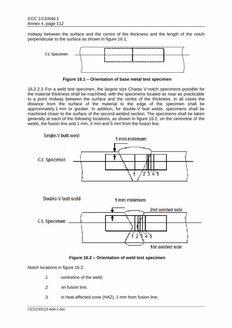
CCC 1/13/Add.1 Annex 4, page 112
I:\CCC\01\13-Add-1.doc
midway between the surface and the centre of the thickness and the length of the notch perpendicular to the surface as shown in figure 16.1.
Figure 16.1 – Orientation of base metal test specimen
16.2.2.3 For a weld test specimen, the largest size Charpy V-notch specimens possible for the material thickness shall be machined, with the specimens located as near as practicable to a point midway between the surface and the centre of the thickness. In all cases the distance from the surface of the material to the edge of the specimen shall be approximately 1 mm or greater. In addition, for double-V butt welds, specimens shall be machined closer to the surface of the second welded section. The specimens shall be taken generally at each of the following locations, as shown in figure 16.2, on the centreline of the welds, the fusion line and 1 mm, 3 mm and 5 mm from the fusion line.
Figure 16.2 – Orientation of weld test specimen
Notch locations in figure 16.2:
.1 centreline of the weld; .2 on fusion line; .3 in heat-affected zone (HAZ), 1 mm from fusion line;

CCC 1/13/Add.1 Annex 4, page 113
I:\CCC\01\13-Add-1.doc
.4 in HAZ, 3 mm from fusion line; and .5 in HAZ, 5 mm from fusion line.
16.2.2.4 If the average value of the three initial Charpy V-notch specimens fails to meet the stated regulations, or the value for more than one specimen is below the required average value, or when the value for one specimen is below the minimum value permitted for a single specimen, three additional specimens from the same material may be tested and the results combined with those previously obtained to form a new average. If this new average complies with the regulations and if no more than two individual results are lower, than the required average and no more than one result is lower than the required value for a single specimen, the piece or batch may be accepted. 16.2.3 Bend test 16.2.3.1 The bend test may be omitted as a material acceptance test, but is required for weld tests. Where a bend test is performed, this shall be done in accordance with recognized standards. 16.2.3.2 The bend tests shall be transverse bend tests, which may be face, root or side bends at the discretion of the Administration or its recognized organization acting on its behalf. However, longitudinal bend tests may be required in lieu of transverse bend tests in cases where the base material and weld metal have different strength levels. 16.2.4 Section observation and other testing 16.2.4.1 Macrosection, microsection observations and hardness tests may also be required by the Administration or its recognized organization acting on its behalf, and they shall be carried out in accordance with recognized standards, where required. 16.3 Welding of metallic materials and non-destructive testing for the fuel
containment system 16.3.1 General 16.3.1.1 This section shall apply to primary and secondary barriers only, including the inner hull where this forms the secondary barrier. Acceptance testing is specified for carbon, carbon-manganese, nickel alloy and stainless steels, but these tests may be adapted for other materials. At the discretion of the Administration or its recognized organization acting on its behalf, impact testing of stainless steel and aluminium alloy weldments may be omitted and other tests may be specially required for any material. 16.3.2 Welding consumables 16.3.2.1 Consumables intended for welding of fuel tanks shall be in accordance with recognized standards. Deposited weld metal tests and butt weld tests shall be required for all consumables. The results obtained from tensile and Charpy V-notch impact tests shall be in accordance with recognized standards. The chemical composition of the deposited weld metal shall be recorded for information. 16.3.3 Welding procedure tests for fuel tanks and process pressure vessels
16.3.3.1 Welding procedure tests for fuel tanks and process pressure vessels are required for all butt welds.

CCC 1/13/Add.1 Annex 4, page 114
I:\CCC\01\13-Add-1.doc
16.3.3.2 The test assemblies shall be representative of:
.1 each base material; .2 each type of consumable and welding process; and .3 each welding position.
16.3.3.3 For butt welds in plates, the test assemblies shall be so prepared that the rolling direction is parallel to the direction of welding. The range of thickness qualified by each welding procedure test shall be in accordance with recognized standards. Radiographic or ultrasonic testing may be performed at the option of the fabricator. 16.3.3.4 The following welding procedure tests for fuel tanks and process pressure vessels shall be done in accordance with 16.2 with specimens made from each test assembly:
.1 cross-weld tensile tests; .2 longitudinal all-weld testing where required by the recognized standards; .3 transverse bend tests, which may be face, root or side bends. However,
longitudinal bend tests may be required in lieu of transverse bend tests in cases where the base material and weld metal have different strength levels;
.4 one set of three Charpy V-notch impacts, generally at each of the following
locations, as shown in figure 16.2:
.1 centreline of the welds;
.2 fusion line;
.3 1 mm from the fusion line;
.4 3 mm from the fusion line; and
.5 5 mm from the fusion line;
.5 macrosection, microsection and hardness survey may also be required. 16.3.3.5 Each test shall satisfy the following:
.1 tensile tests: cross-weld tensile strength is not to be less than the specified minimum tensile strength for the appropriate parent materials. For aluminium alloys, reference shall be made to 6.4.12.1.1.3 with regard to the regulations for weld metal strength of under-matched welds (where the weld metal has a lower tensile strength than the parent metal). In every case, the position of fracture shall be recorded for information;
.2 bend tests: no fracture is acceptable after a 180° bend over a former of a
diameter four times the thickness of the test pieces; and

CCC 1/13/Add.1 Annex 4, page 115
I:\CCC\01\13-Add-1.doc
.3 Charpy V-notch impact tests: Charpy V-notch tests shall be conducted at the temperature prescribed for the base material being joined. The results of weld metal impact tests, minimum average energy (KV), shall be no less than 27 J. The weld metal regulations for sub-size specimens and single energy values shall be in accordance with 16.2.2. The results of fusion line and heat affected zone impact tests shall show a minimum average energy (KV) in accordance with the transverse or longitudinal regulations of the base material, whichever is applicable, and for sub-size specimens, the minimum average energy (KV) shall be in accordance with 16.2.2. If the material thickness does not permit machining either full-size or standard sub-size specimens, the testing procedure and acceptance standards shall be in accordance with recognized standards.
16.3.3.6 Procedure tests for fillet welding shall be in accordance with recognized standards. In such cases, consumables shall be so selected that exhibit satisfactory impact properties. 16.3.4 Welding procedure tests for piping 16.3.4.1 Welding procedure tests for piping shall be carried out and shall be similar to those detailed for fuel tanks in 16.3.3. 16.3.5 Production weld tests 16.3.5.1 For all fuel tanks and process pressure vessels except membrane tanks, production weld tests shall generally be performed for approximately each 50 m of butt-weld joints and shall be representative of each welding position. For secondary barriers, the same type production tests as required for primary tanks shall be performed, except that the number of tests may be reduced subject to agreement with the Administration or its recognized organization acting on its behalf. Tests, other than those specified in 16.3.5.2 to 16.3.5.5 may be required for fuel tanks or secondary barriers. 16.3.5.2 The production tests for types A and B independent tanks shall include bend tests and, where required for procedure tests, one set of three Charpy V-notch tests. The tests shall be made for each 50 m of weld. The Charpy V-notch tests shall be made with specimens having the notch alternately located in the centre of the weld and in the heat affected zone (most critical location based on procedure qualification results). For austenitic stainless steel, all notches shall be in the centre of the weld. 16.3.5.3 For type C independent tanks and process pressure vessels, transverse weld tensile tests are required in addition to the tests listed in 16.3.5.2. Tensile tests shall meet regulation 16.3.3.5. 16.3.5.4 The quality assurance/quality control (QA/QC) program shall ensure the continued conformity of the production welds as defined in the material manufacturers quality manual (QM). 16.3.5.5 The test regulations for membrane tanks are the same as the applicable test regulations listed in 16.3.3.
16.3.6 Non-destructive testing
16.3.6.1 All test procedures and acceptance standards shall be in accordance with recognized standards, unless the designer specifies a higher standard in order to meet design assumptions. Radiographic testing shall be used in principle to detect internal defects.

CCC 1/13/Add.1 Annex 4, page 116
I:\CCC\01\13-Add-1.doc
However, an approved ultrasonic test procedure in lieu of radiographic testing may be conducted, but in addition supplementary radiographic testing at selected locations shall be carried out to verify the results. Radiographic and ultrasonic testing records shall be retained. 16.3.6.2 For type A independent tanks where the design temperature is below -20°C, and for type B independent tanks, regardless of temperature, all full penetration butt welds of the shell plating of fuel tanks shall be subjected to non-destructive testing suitable to detect internal defects over their full length. Ultrasonic testing in lieu of radiographic testing may be carried out under the same conditions as described in 16.3.6.1. 16.3.6.3 In each case the remaining tank structure, including the welding of stiffeners and other fittings and attachments, shall be examined by magnetic particle or dye penetrant methods as considered necessary. 16.3.6.4 For type C independent tanks, the extent of non-destructive testing shall be total or partial according to recognized standards, but the controls to be carried out shall not be less than the following: .1 Total non-destructive testing referred to in 6.4.15.3.2.1.3 Radiographic testing:
.1 all butt welds over their full length. Non-destructive testing for surface crack detection:
.2 all welds over 10% of their length; .3 reinforcement rings around holes, nozzles, etc. over their full length.
As an alternative, ultrasonic testing, as described in 16.3.6.1, may be accepted as a partial substitute for the radiographic testing. In addition, the Administration or its recognized organization acting on its behalf may require total ultrasonic testing on welding of reinforcement rings around holes, nozzles, etc.
.2 Partial non-destructive testing referred to in 6.4.15.3.2.1.3:
Radiographic testing:
.1 all butt welded crossing joints and at least 10% of the full length of butt welds at selected positions uniformly distributed.
Non-destructive testing for surface crack detection:
.2 reinforcement rings around holes, nozzles, etc. over their full length.
Ultrasonic testing:
.3 as may be required by the Administration or recognized organization acting on its behalf in each instance.
16.3.6.5 The quality assurance/quality control (QA/QC) program shall ensure the continued conformity of the non-destructive testing of welds, as defined in the material manufacturer's quality manual (QM).

CCC 1/13/Add.1 Annex 4, page 117
I:\CCC\01\13-Add-1.doc
16.3.6.6 Inspection of piping shall be carried out in accordance with the regulations of chapter 7. 16.3.6.7 The secondary barrier shall be non-destructive tested for internal defects as considered necessary. Where the outer shell of the hull is part of the secondary barrier, all sheer strake butts and the intersections of all butts and seams in the side shell shall be tested by radiographic testing. 16.4 Other regulations for construction in metallic materials 16.4.1 General Inspection and non-destructive testing of welds shall be in accordance with regulations in 16.3.5 and 16.3.6. Where higher standards or tolerances are assumed in the design, they shall also be satisfied. 16.4.2 Independent tank For type C tanks and type B tanks primarily constructed of bodies of revolution the tolerances relating to manufacture, such as out-of-roundness, local deviations from the true form, welded joints alignment and tapering of plates having different thicknesses, shall comply with recognized standards. The tolerances shall also be related to the buckling analysis referred to in 6.4.15.2.3.1 and 6.4.15.3.3.2. 16.4.3 Secondary barriers During construction the regulations for testing and inspection of secondary barriers shall be approved or accepted by the Administration or recognized organization acting on its behalf (see also 6.4.4.2.5 and 6.4.4.2.6). 16.4.4 Membrane tanks The quality assurance/quality control (QA/QC) program shall ensure the continued conformity of the weld procedure qualification, design details, materials, construction, inspection and production testing of components. These standards and procedures shall be developed during the prototype testing programme. 16.5 Testing 16.5.1 Testing and inspections during construction 16.5.1.1 All liquefied gas fuel tanks and process pressure vessels shall be subjected to hydrostatic or hydro-pneumatic pressure testing in accordance with 16.5.2 to 16.5.5, as applicable for the tank type. 16.5.1.2 All tanks shall be subject to a tightness test which may be performed in combination with the pressure test referred to in 16.5.1.1. 16.5.1.3 The gas tightness of the fuel containment system with reference to 6.3.3 shall be tested. 16.5.1.4 Regulations with respect to inspection of secondary barriers shall be decided by the Administration or its recognized organization acting on its behalf in each case, taking into account the accessibility of the barrier (see also 6.4.4.2).

CCC 1/13/Add.1 Annex 4, page 118
I:\CCC\01\13-Add-1.doc
16.5.1.5 The Administration or its recognized organization acting on its behalf may require that for ships fitted with novel type B independent tanks, or tanks designed according to 6.4.16 at least one prototype tank and its support shall be instrumented with strain gauges or other suitable equipment to confirm stress levels during the testing required in 16.5.1.1. Similar instrumentation may be required for type C independent tanks, depending on their configuration and on the arrangement of their supports and attachments. 16.5.1.6 The overall performance of the fuel containment system shall be verified for compliance with the design parameters during the first LNG bunkering, when steady thermal conditions of the liquefied gas fuel are reached, in accordance with the requirements of the Administration or its recognized organization acting on its behalf. Records of the performance of the components and equipment, essential to verify the design parameters, shall be maintained on board and be available to the Administration. 16.5.1.7 The fuel containment system shall be inspected for cold spots during or immediately following the first LNG bunkering, when steady thermal conditions are reached. Inspection of the integrity of thermal insulation surfaces that cannot be visually checked shall be carried out in accordance with the requirements of the Administration or its recognized organization acting on its behalf. 16.5.1.8 Heating arrangements, if fitted in accordance with 6.4.13.1.1.4 and 6.4.13.1.1.5, shall be tested for required heat output and heat distribution. 16.5.2 Type A independent tanks
16.5.2.1 All type A independent tanks shall be subjected to a hydrostatic or hydro-pneumatic pressure testing. This test shall be performed such that the stresses approximate, as far as practicable, the design stresses, and that the pressure at the top of the tank corresponds at least to the MARVS. When a hydropneumatic test is performed, the conditions should simulate, as far as practicable, the design loading of the tank and of its support structure including dynamic components, while avoiding stress levels that could cause permanent deformation. 16.5.3 Type B independent tanks 16.5.3.1 Type B independent tanks shall be subjected to a hydrostatic or hydro-pneumatic pressure testing as follows:
.1 The test shall be performed as required in 16.5.2.1 for type A independent tanks.
.2 In addition, the maximum primary membrane stress or maximum bending
stress in primary members under test conditions shall not exceed 90% of the yield strength of the material (as fabricated) at the test temperature. To ensure that this condition is satisfied, when calculations indicate that this stress exceeds 75% of the yield strength the test of the first of a series of identical tanks shall be monitored by the use of strain gauges or other suitable equipment.
16.5.4 Type C independent tanks and other pressure vessels 16.5.4.1 Each pressure vessel shall be subjected to a hydrostatic test at a pressure measured at the top of the tanks, of not less than 1.5 P0. In no case during the pressure test shall the calculated primary membrane stress at any point exceed 90% of the yield strength

CCC 1/13/Add.1 Annex 4, page 119
I:\CCC\01\13-Add-1.doc
of the material at the test temperature. To ensure that this condition is satisfied where calculations indicate that this stress will exceed 0.75 times the yield strength, the test of the first of a series of identical tanks shall be monitored by the use of strain gauges or other suitable equipment in pressure vessels other than simple cylindrical and spherical pressure vessels. 16.5.4.2 The temperature of the water used for the test shall be at least 30°C above the nil-ductility transition temperature of the material, as fabricated. 16.5.4.3 The pressure shall be held for 2 hours per 25 mm of thickness, but in no case less than 2 hours. 16.5.4.4 Where necessary for liquefied gas fuel pressure vessels, a hydro-pneumatic test may be carried out under the conditions prescribed in 16.5.4.1 to 16.5.4.3. 16.5.4.5 Special consideration may be given to the testing of tanks in which higher allowable stresses are used, depending on service temperature. However, regulation in 16.5.4.1 shall be fully complied with. 16.5.4.6 After completion and assembly, each pressure vessel and its related fittings shall be subjected to an adequate tightness test, which may be performed in combination with the pressure testing referred to in 16.5.4.1 or 16.5.4.4 as applicable. 16.5.4.7 Pneumatic testing of pressure vessels other than liquefied gas fuel tanks shall be considered on an individual case basis. Such testing shall only be permitted for those vessels designed or supported such that they cannot be safely filled with water, or for those vessels that cannot be dried and are to be used in a service where traces of the testing medium cannot be tolerated. 16.5.5 Membrane tanks 16.5.5.1 Design development testing 16.5.5.1.1 The design development testing required in 6.4.15.4.1.2 shall include a series of analytical and physical models of both the primary and secondary barriers, including corners and joints, tested to verify that they will withstand the expected combined strains due to static, dynamic and thermal loads at all filling levels. This will culminate in the construction of a prototype scaled model of the complete liquefied gas fuel containment system. Testing conditions considered in the analytical and physical model shall represent the most extreme service conditions the liquefied gas fuel containment system will be likely to encounter over its life. Proposed acceptance criteria for periodic testing of secondary barriers required in 6.4.4.2 shall be based on the results of testing carried out on the prototype scaled model. 16.5.5.1.2 The fatigue performance of the membrane materials and representative welded or bonded joints in the membranes shall be determined by tests. The ultimate strength and fatigue performance of arrangements for securing the thermal insulation system to the hull structure shall be determined by analyses or tests. 16.5.5.2 Testing
.1 In ships fitted with membrane liquefied gas fuel containment systems, all tanks and other spaces that may normally contain liquid and are adjacent to the hull structure supporting the membrane, shall be hydrostatically tested.

CCC 1/13/Add.1 Annex 4, page 120
I:\CCC\01\13-Add-1.doc
.2 All hold structures supporting the membrane shall be tested for tightness before installation of the liquefied gas fuel containment system.
.3 Pipe tunnels and other compartments that do not normally contain liquid need not be hydrostatically tested.
16.6 Welding, post-weld heat treatment and non-destructive testing
16.6.1 General
Welding shall be carried out in accordance with 16.3.
16.6.2 Post-weld heat treatment
Post-weld heat treatment shall be required for all butt welds of pipes made with carbon, carbon-manganese and low alloy steels. The Administration or its recognized organization acting on its behalf may waive the regulations for thermal stress relieving of pipes with wall thickness less than 10 mm in relation to the design temperature and pressure of the piping system concerned.
16.6.3 Non-destructive testing
In addition to normal controls before and during the welding, and to the visual inspection of the finished welds, as necessary for proving that the welding has been carried out correctly and according to the regulations in this paragraph, the following tests shall be required:
.1 100% radiographic or ultrasonic inspection of butt-welded joints for piping systems with;
.1 design temperatures colder than -10°C; or
.2 design pressure greater than 10 bar; or
.3 gas supply pipes in ESD protected machinery spaces; or
.4 inside diameters of more than 75 mm; or
.5 wall thicknesses greater than 10 mm.
.2 When such butt welded joints of piping sections are made by automatic welding procedures approved by the Administration or its recognized organization acting on its behalf, then a progressive reduction in the extent of radiographic or ultrasonic inspection can be agreed, but in no case to less than 10% of each joint. If defects are revealed the extent of examination shall be increased to 100% and shall include inspection of previously accepted welds. This approval can only be granted if well-documented quality assurance procedures and records are available to assess the ability of the manufacturer to produce satisfactory welds consistently.
.3 The radiographic or ultrasonic inspection regulation may be reduced to 10% for butt-welded joints in the outer pipe of double-walled fuel piping.
.4 For other butt-welded joints of pipes not covered by 16.6.3.1 and 16.6.3.3, spot radiographic or ultrasonic inspection or other non-destructive tests shall be carried out depending upon service, position and materials. In general, at least 10% of butt-welded joints of pipes shall be subjected to radiographic or ultrasonic inspection.

CCC 1/13/Add.1 Annex 4, page 121
I:\CCC\01\13-Add-1.doc
16.7 Testing regulations
16.7.1 Type testing of piping components
Valves
Each type of piping component intended to be used at a working temperature below -55°C shall be subject to the following type tests:
.1 Each size and type of valve shall be subjected to seat tightness testing over the full range of operating pressures and temperatures, at intervals, up to the rated design pressure of the valve. Allowable leakage rates shall be to the requirements of the Administration or its recognized organization acting on its behalf. During the testing satisfactory operation of the valve shall be verified.
.2 The flow or capacity shall be certified to a recognized standard for each size and type of valve.
.3 Pressurized components shall be pressure tested to at least 1.5 times the design pressure.
.4 For emergency shutdown valves, with materials having melting temperatures lower than 925°C, the type testing shall include a fire test to a standard acceptable to the Administration or its recognized organization acting on its behalf.32
16.7.2 Expansion bellows
The following type tests shall be performed on each type of expansion bellows intended for use on fuel piping outside the fuel tank as found acceptable in 7.3.6.4.3.1.3 and where required by the Administration or its recognized organization acting on its behalf, on those installed within the fuel tanks:
.1 Elements of the bellows, not pre-compressed, but axially restrained shall be pressure tested at not less than five times the design pressure without bursting. The duration of the test shall not be less than five minutes.
.2 A pressure test shall be performed on a type expansion joint, complete with all the accessories such as flanges, stays and articulations, at the minimum design temperature and twice the design pressure at the extreme displacement conditions recommended by the manufacturer without permanent deformation.
.3 A cyclic test (thermal movements) shall be performed on a complete expansion joint, which shall withstand at least as many cycles under the conditions of pressure, temperature, axial movement, rotational movement and transverse movement as it will encounter in actual service. Testing at ambient temperature is permitted when this testing is at least as severe as testing at the service temperature.
32 Refer to the recommendations by the International Organization for Standardization, in particular publications:
ISO 19921:2005, Ships and marine technology – Fire resistance of metallic pipe components with resilient and elastomeric seals – Test methods
ISO 19922:2005, Ships and marine technology – Fire resistance of metallic pipe components with resilient and elastomeric seals – Requirements imposed on the test bench

CCC 1/13/Add.1 Annex 4, page 122
I:\CCC\01\13-Add-1.doc
.4 A cyclic fatigue test (ship deformation, ship accelerations and pipe vibrations) shall be performed on a complete expansion joint, without internal pressure, by simulating the bellows movement corresponding to a compensated pipe length, for at least 2,000,000 cycles at a frequency not higher than 5 Hz. This test is only required when, due to the piping arrangement, ship deformation loads are actually experienced.
16.7.3 System testing regulations
16.7.3.1 The regulations for testing in this section apply to gas piping inside and outside the gas tanks. However, relaxation from these regulations for piping inside gas tanks and open ended piping may be accepted by the Administration or its recognized organization acting on its behalf.
16.7.3.2 After assembly, all fuel piping shall be subjected to a strength test with a suitable fluid. The test pressure shall be at least 1.5 times the design pressure for liquid lines and 1.5 times the maximum system working pressure for vapour lines. When piping systems or parts of systems are completely manufactured and equipped with all fittings, the test may be conducted prior to installation on board the ship. Joints welded on board shall be tested to at least 1.5 times the design pressure.
16.7.3.3 After assembly on board, the fuel piping system shall be subjected to a leak test using air, or other suitable medium to a pressure depending on the leak detection method applied.
16.7.3.4 In double wall fuel piping systems the outer pipe or duct shall also be pressure tested to show that it can withstand the expected maximum pressure at pipe rupture.
16.7.3.5 All piping systems, including valves, fittings and associated equipment for handling fuel or vapours, shall be tested under normal operating conditions not later than at the first bunkering operation, in accordance with the requirements of the Administration or its recognized organization acting on its behalf.
16.7.3.6 Emergency shutdown valves in liquefied gas piping systems shall close fully and smoothly within 30 s of actuation. Information about the closure time of the valves and their operating characteristics shall be available on board, and the closing time shall be verifiable and repeatable.
16.7.3.7 The closing time of the valve referred to in 8.5.8 and 15.4.2.2 (i.e. time from shutdown signal initiation to complete valve closure) shall not be greater than:
(second)
where:
U = ullage volume at operating signal level (m3);
BR = maximum bunkering rate agreed between ship and shore facility (m3/h); or
5 seconds, whichever is the least.
The bunkering rate shall be adjusted to limit surge pressure on valve closure to an acceptable level, taking into account the bunkering hose or arm, the ship and the shore piping systems, where relevant.

CCC 1/13/Add.1 Annex 4, page 123
I:\CCC\01\13-Add-1.doc
PART C
17 TRAINING 17.1 Goal The goal of this chapter is to ensure that seafarers onboard ships to which this Code apply are adequately qualified, trained and experienced. 17.2 Functional requirements Companies shall ensure that seafarers on board ships using gases or other low-flashpoint fuels shall have completed training to attain the abilities that are appropriate to the capacity to be filled and duties and responsibilities to be taken up, taking into account the provisions given in the STCW Convention and Code, as amended. 17.3 Drills and emergency exercises Drills and emergency exercises on board shall be conducted at regular intervals. Such gas-related exercises could include for example:
.1 tabletop exercise;
.2 review of fueling procedures based in the fuel handling manual required by
18.2.3;
.3 responses to potential contingences;
.4 tests of equipment intended for contingency response; and
.5 reviews that assigned seafarers are trained to perform assigned duties
during fuelling and contingency response.
Gas related exercises may be incorporated into periodical drills required by SOLAS.
The response and safety system for hazards and accident control shall be reviewed and tested. 18 OPERATION
18.1 Goal The goal of this chapter is to ensure that operational procedures for the loading, storage, operation, maintenance, and inspection of systems for gas or low-flashpoint fuels minimize the risk to personnel, the ship and the environment and that are consistent with practices for a conventional oil fuelled ship whilst taking into account the nature of the liquid or gaseous fuel.

CCC 1/13/Add.1 Annex 4, page 124
I:\CCC\01\13-Add-1.doc
18.2 Functional requirements
This chapter relates to the functional requirements in 3.2.1 to 3.2.3, 3.2.9, 3.2.11, 3.2.15,
3.2.16 and 3.2.17. In particular the following apply:
.1 A copy of this Code, or national regulations incorporating the provisions of this Code, shall be on board every ship covered by this Code.
.2 Maintenance procedures and information for all gas related installations shall be available on board.
.3 The ship shall be provided with operational procedures including a suitably detailed fuel handling manual, such that trained personnel can safely operate the fuel bunkering, storage and transfer systems.
.4 The ship shall be provided with suitable emergency procedures.
18.3 Regulations for maintenance
18.3.1 Maintenance and repair procedures shall include considerations with respect to the tank location and adjacent spaces (see chapter 5).
18.3.2 In-service survey, maintenance and testing of the fuel containment system are to be carried out in accordance with the inspection/survey plan required by 6.4.1.8.
18.3.3 The procedures and information shall include maintenance of electrical equipment that is installed in explosion hazardous spaces and areas. The inspection and maintenance of electrical installations in explosion hazardous spaces shall be performed in accordance with a recognized standard.33
18.4 Regulations for bunkering operations
18.4.1 Responsibilities
Before any bunkering operation commences, the master of the receiving ship or his representative and the representative of the bunkering source (Persons In Charge, PIC) shall:
.1 Agree in writing the transfer procedure, including cooling down and if necessary, gassing up; the maximum transfer rate at all stages and volume to be transferred.
.2 Agree in writing action to be taken in an emergency.
.3 Complete and sign the bunker safety check-list.
18.4.2 Overview of control, automation and safety systems
18.4.2.1 The fuel handling manual required by 18.2.3 shall include but is not limited to:
.1 overall operation of the ship from dry-dock to dry-dock, including procedures for system cool down and warm up, bunker loading and, where appropriate, discharging, sampling, inerting and gas freeing;
.2 bunker temperature and pressure control and alarm and safety systems;
33 Refer to IEC 60079 17:2007 Explosive atmospheres – part 17: Electrical installations inspection and
maintenance.

CCC 1/13/Add.1 Annex 4, page 125
I:\CCC\01\13-Add-1.doc
.3 system limitations, cool down rates and maximum fuel storage tank temperatures prior to bunkering, including minimum fuel temperatures, maximum tank pressures, transfer rates, filling limits and sloshing limitations;
.4 operation of inert gas systems; .5 firefighting and emergency procedures: operation and maintenance of
firefighting systems and use of extinguishing agents; .6 specific fuel properties and special equipment needed for the safe handling
of the particular fuel; .7 fixed and portable gas detection operation and maintenance of equipment; .8 emergency shutdown and emergency release systems, where fitted; and .9 a description of the procedural actions to take in an emergency situation,
such as leakage or fire.
18.4.2.2 A fuel system schematic/piping and instrumentation diagram (P&ID) shall be reproduced and permanently mounted in the vessels' bunker control station and at the bunker station.
18.4.3 Pre-bunkering verification
18.4.3.1 Prior to conducting bunkering operations, pre-bunkering verification including, but not limited to the following, shall be carried out and documented in the bunker safety checklist:
.1 all communications methods, including ship shore link (SSL), if fitted; .2 operation of fixed gas and fire detection equipment; .3 operation of portable gas detection equipment; .4 operation of remote controlled valves; and
.5 inspection of hoses and couplings.
18.4.3.2 Documentation of successful verification shall be indicated by the mutually agreed and executed bunkering safety checklist signed by both PIC's. 18.4.4 Ship bunkering source communications 18.4.4.1 Communications shall be maintained between the vessel PIC and the bunkering source PIC at all times during the bunkering operation. In the event that communications cannot be maintained, bunkering shall stop and not resume until communications are restored. 18.4.4.2 Communication devices used in bunkering shall comply with recognized standards for such devices acceptable to the Administration or its recognized organization acting on its behalf.
CCC 1/13/Add.1 Annex 4, page 126
I:\CCC\01\13-Add-1.doc
18.4.4.3 PIC's shall have direct and immediate communication with all personnel involved in the bunkering operation. 18.4.4.4 The ship shore link (SSL) or equivalent means to a bunkering source provided for automatic ESD communications, shall be compatible with the receiving vessel and the delivering facility ESD system.34 18.4.5 Electrical bonding Hoses, transfer arms, piping and fittings provided by the delivering facility used for bunkering shall be electrically continuous, suitably insulated and shall provide a level of safety compliant with recognized standards.35 18.4.6 Conditions for transfer 18.4.6.1 Warning signs shall be posted at the access points to the bunkering area listing fire safety precautions during fuel transfer. 18.4.6.2 During the transfer operation, personnel in the bunkering manifold area shall be limited to essential staff only. All staff engaged in duties or working in the vicinity of the operations shall wear appropriate personal protective equipment (PPE). A failure to maintain the required conditions for transfer shall be cause to stop operations and transfer shall not be resumed until all required conditions are met. 18.4.6.3 Where bunkering is to take place via the installation of portable tanks, the procedure shall provide an equivalent level of safety as integrated fuel tanks and systems. Portable tanks shall be filled prior to loading on board the vessel and shall be properly secured prior to connection to the fuel system. 18.4.6.4 For tanks not permanently installed in the vessel, the connection of all necessary tank systems (piping, controls, safety system, relief system, etc.) to the fuel system of the ship is part of the "bunkering" process and shall be finished prior to ship departure from the bunkering source. Connecting and disconnecting of portable tanks during the sea voyage or manoeuvring is not permitted. 18.5 Regulations for enclosed space entry 18.5.1 Under normal operational circumstances, personnel shall not enter fuel tanks, fuel storage hold spaces, void spaces, tank connection spaces or other enclosed spaces where gas or flammable vapours may accumulate, unless the gas content of the atmosphere in such space is determined by means of fixed or portable equipment to ensure oxygen sufficiency and absence of an explosive atmosphere.36 18.5.2 Personnel entering any space designated as a hazardous area shall not introduce any potential source of ignition into the space unless it has been certified gas-free and maintained in that condition.
34 Refer to ISO 28460, ship-shore interface and port operations. 35 Refer to API RP 2003, ISGOTT: International Safety Guide for Oil Tankers and Terminals. 36 Refer to the Revised recommendations for entering enclosed spaces aboard ships (A.1050(27)).

CCC 1/13/Add.1 Annex 4, page 127
I:\CCC\01\13-Add-1.doc
18.6 Regulations for inerting and purging of fuel systems 18.6.1 The primary objective in inerting and purging of fuel systems is to prevent the formation of a combustible atmosphere in, near or around fuel system piping, tanks, equipment and adjacent spaces. 18.6.2 Procedures for inerting and purging of fuel systems shall ensure that air is not introduced into piping or a tank containing gas atmospheres, and that gas is not introduced into air contained in enclosures or spaces adjacent to fuel systems. 18.7 Regulations for hot work on or near fuel systems 18.7.1 Hot work in the vicinity of fuel tanks, fuel piping and insulation systems that may be flammable, contaminated with hydrocarbons, or that may give off toxic fumes as a product of combustion shall only be undertaken after the area has been secured and proven safe for hot work and all approvals have been obtained.
___________


![news.wko.at3107]-03... · Web viewRules on the carriage of dangerous cargoes and the ships that carry these cargoes are found in the International Convention for the Safety of Life](https://static.fdocuments.in/doc/165x107/5e24e6b2ed8fa930380e4aef/newswkoat-3107-03-web-view-rules-on-the-carriage-of-dangerous-cargoes-and.jpg)
