E S I M D LOW S F C T 460 5732
32
Bulletin 310-E Metric CERTIFIED EN ISO 9001 NEW! NEW! NEW! NEW! ENERGY SAVING, EASY TO INSTALL AND MAINTAIN, FORCED DRAFT AXIAL SUPER LOW SOUND FAN COOLING TOWERS T HERMAL PERFORMANCE FROM 460 TO 5732 K W NOMINAL CAPACITY D ELIVERING Q UALITY ... F OCUSED ON P ERFECTION ! Mr. GoodTower ® Mark owned by the Cooling Technology Institute
Transcript of E S I M D LOW S F C T 460 5732

Bulletin 310-E Metric
C E R T I F I E D E N I S O 9 0 0 1
NEW!NEW!NEW!NEW!
ENERGY SAVING, EASY TO INSTALL AND MAINTAIN, FORCED DRAFT
AXIAL SUPER LOW SOUND FAN COOLING TOWERS
THERMAL PERFORMANCE FROM 460 TO 5732 KW NOMINAL CAPACITY
D E L I V E R I N G Q U A L I T Y. . . F O C U S E D O N P E R F E C T I O N !
Mr. GoodTower®
Mark owned by the Cooling Technology Institute

2
Patented EVAPAK® Fill• Contructed of PVC, will notrot or decay
• Excellent fire resistant qualities• Structural integrity makes itstrong enough to beused as aworking platform
• Environmental friendly weldedblocks
Standard Man SizeAccess Door• Enhanced Basin Accessibility• Easy Basin Cleaning• Easy Access to Internal Components
Super Low SoundFan Technology• One Piece MoldedHeavy Duty FRP Construction
• Sound level reduction10-13 dBA on fan side @ 15 m
T E C H N O L O G Y F O R T H E
NEWNEW
NEWNEW
EVAPCO is proud to introduce theSuper Low Sound Technology forForced Draft Axial Fan Cooling Towers
Standard Man-sizedAccess Door
S ince its founding in 1976,EVAPCO, Inc. has become aworld-wide leader in supplying
quality cooling equipment forthousands of customers in both thecommercial and industrial markets.
EVAPCO’s success has been the result ofa continual commitment to productimprovement, quality workmanshipand a dedication to providingunparalleled service.
Our emphasis on research anddevelopment has led to many productinnovations – a hallmark of EVAPCOthrough the years.
The ongoing R & D Program enablesEVAPCO to provide the most advancedproducts in the industry – technologyfor the future, available today.
With 19 facilities in nine countries andover 175 sales offices in 51 countriesworld-wide, EVAPCO is ready to assistin all your equipment needs.
EvapJet™ Water Distribution System• Large orifice prevents clogging (no moving parts).• Fluidic Spray Technology provides complete fill pack coverage• Precision molded ABS for superior corrosion resistance• Superior corrosion resistance• Guaranteed for life
U.S. Patent No. 5124087

3
Sloped Pan Bottom• Pan bottom slopes to drain• Easy to clean• Stainless steel strainerresists corrosion
Individual Fan Drive System -STANDARD• Increased flexibility for improvedcapacity control
• Greater reliability through redundancy• Easy motor replacement• Front mounted drives for improvedmaintenance accessibility
Unique Field Seam• Eliminates up to 85% of fasteners• Self guiding channels improve qualityof field seam to eliminate leaks
• Easy to install• Lower installation cost
Double-Breake Flange Joints• Stronger than single-brake designsby others
•Minimizes water leaks at field joints• Greater structural integrity
Water Saver Drift Eliminators• New patented design reduces driftrate to 0.001%
• Saves water and reduces watertreatment cost
• Greater structural integrity vs. oldstyle blade-type
• Recessed into casing for greaterprotection
• Drift rate certifications as perEurovent OM-14-2009
F U T U R E , A V A I L A B L E T O D A Y !
NEWNEW
NEWNEW
NEWNEW
EVAPCO is proud to introduce the latest in evaporative cooling towertechnology, the PMTQ. This Open Cooling Tower features Quiet Super LowSound Technology and is Easy to install, Easy to maintain and Energy Saving!
DESIGN AND CONSTRUCTION FEATURES
DESIG
NMAINTENANCE
OPTIO
NS
IBC
CTI-ECC
ENGINEERING
SOUND
SPECIFICATIONS
†
CTI-ECCCertifiedRefer to page13 for details
CT N° : 12.02.010Range : PMTQ
† Mark owned by theCooling Technology Institute

4
DE S I G N F E AT U R E S
Proven Performance & Design FlexibilityThe new PMTQ Cooling Tower offers more capacity and greater systemdesign flexibility than ever before. EVAPCO's research and developmentteam has invested hundreds of hours in laboratory testing to develop thenext generation in Forced Draft Cooling Tower Technology. These effortshave produced a totally new fan section design which is now combinedwith the proven EVAPAK® Fill technology to offer improved performance.
The PMTQ features more plan area options and fan horsepower optionsfor the system design engineer. With more capacity, more plan areaoptions and greater flexibility in motor selection, the design engineer cannow match the performance to the specific application requirements.More equipment choices and more design flexibility mean greater valuefor the End-User.
Patented EVAPAK® FillThe Evapak® film type fill design used in the PMTQ Cooling Tower line isspecially designed to induce highly turbulent mixing of the air and waterfor heat transfer. Special drainage tips allow high water loadings withoutexcessive pressure drop. The fill is constructed of inert polyvinyl chloride,(PVC). It will not rot or decay and is formulated to withstand watertemperatures of 55°C. The fill also has excellent fire resistant qualitiesproviding a flame spread rating of 5 per ASTM-E84-81a. (The flamespread rating scale ranges from 0 for non-combustible to 100 for highlycombustible). Because of the unique way in which the cross-fluted sheetsare welded together, the structural integrity of the fill is greatlyenhanced, making the fill usable as a working platform.
A high temperature fill is available for water temperatures exceeding55°C. Consult your EVAPCO representative for further details.
Energy Efficient for Lowest Operating Cost
Lower Horsepower Options
The new fan drive system of the PMTQ utilizes larger diameter vane-axial fans in a two stage arrangement to providemore efficient air flow and reduced power consumption. When compared to the traditional centrifugal fan cooling towermodels, the vane-axial fan design can offer up to a 50% reduction in energy consumption. And, with the new PMCQmodel selections even more low horsepower options are available to obtain greater energy savings.
Individual Fan Drive SystemCapacity Control Flexibility & Operating Redundancy
The new PMTQ fan drive system provides individualmotor to fan configuration as standard equipment onall models. The dedicated fan to motor arrangementensures less “wear & tear” on the drive system versustandem fan motor drive arrangements resulting in lessmaintenance. The individual motor to fan designoffers greater capacity control flexibility to match thesystem load requirements. In addition, all Evapcotowers are equipped with an internal baffle in thepan bottom vertically up. This unique design allowsthe user to cycle fan motors independently withoutharmful effects of air by-pass inside the unit. Theindividual motor to fan design ensures maximumoperating redundancy in the tower fan system whencritical operation is necessary.
*U.S. Patent No. 4755331
DESIG
NE A S Y S O L U T I O N S , B E T T E R C H O I C E S !

5
EVAPCOAT Corrosion Protection System
The Z-725 Mill Hot-Dip Galvanized Steel Construction is theheaviest level of galvanizing available for manufacturingevaporative cooling towers and has more zinc protection thancompetitive designs using Z-275 and Z-600 steel.
There are various grades of mill galvanized steel each withdiffering amounts of zinc protection. EVAPCO has been a leaderin the industry in developing heavier galvanizing, and was thefirst to standardize on Z-725 mill hot-dip galvanized steel. Z-725designation means there is a minimum of 725 g/m2 total zincpresent on the steel. During fabrication, all panel edges arecoated with a 95% pure zinc-rich compound for extendedcorrosion resistance.
85% Fewer Fasteners - Lower Installed Cost
The PMTQ features a new field seam design which ensures easierassembly and fewer field seam leaks. The field seam incorporatesnew self-guiding channels to guide the fill section into positionand set in place on the bottom fan section of the tower. Inaddition, the new design eliminates up to 85% of the fastenerstypically used to join the sections in the field significantly reducingthe contractor labor costs for installation.
Unique Seam Design - Eliminate Field Leaks
The new PMTQ features Evapco's unique panel construction designwhich includes a special butyl tape sealer with an integral sealinggasket. Each joint is then backed with a secondary caulkingcompound and encased in a double-brake flange for addedstrength and structural integrity. This unique sealing system hasbeen proven effective in both laboratory tests and years of fieldapplication.
Superior Water Saver Drift Eliminators
The PMTQ incorporate a patented* highly efficient PVC drifteliminator. The eliminator removes entrained water droplets from theair stream to limit the drift rate to less than 0.001% of therecirculating water rate. The efficient of the eliminators is certified byEurovent and tested in accordance with OM-14-2009. Please consultwww.eurovent-certification.com for additional informations.
With a low drift rate, PMTQ towers save valuable water and watertreatment chemicals. The eliminators feature a honeycomb designwhich offers greater structural integrity and are recessed in the top ofthe casing for longer life. They are constructed of inert polyvinylchloride (PVC) which eliminates corrosion in this critical area of thetower. The eliminators are assembled in sections for easy handlingand removal for fill and water distribution system inspection.
*U.S. Patent No. 631580481
OverlaySealant
Anti-LeakSealer Strip
IntegralCompressionShim
DE S I G N F E AT U R E S
ZINC
ZINC
STEELZ-725
Z-600
Z-275
EVAPCO
OTHERS
DESIG
N
E A S Y S O L U T I O N S , B E T T E R C H O I C E S !

6
MA I N T E N A N C E AD VA N TA G E S
Improved MaintenanceOversized Access Door
For enhanced basin accessibility, the Oversized Access Doors enablemaintenance personnel to quickly and easily enter the basin for floatvalve adjustment and unit inspection, cleaning and maintenance.
Fan Drive Accessibility
The drive components of the PMTQ are easily accessed for routinemaintenance from the front of the unit. Bearing grease fittings areextended to the outside of the unit for ease of lubrication. All drivesheaves have been relocated to the front of the fan section and motorsare positioned on a platform base to allow for easy belt tensionadjustment.
Pressurized Water Distribution System
The water distribution system is made of schedule 40 PVC pipe andABS plastic water diffusers for corrosion protection in this key area.The piping is easily removable for cleaning. The water diffusers havea large orifice and are practically impossible to clog.In addition, the spray branches have threaded endcaps to allow easy debris removal.
All PMTQ units have as per standard the EvapJet™Nozzle to ensure that every square meter of heattransfer surface receives complete and even watercoverage by the oscillating water spray, resulting inmaximum thermal performance.
Easy Clean Sloped Basin
The PMTQ drain pan is designed to improve maintenance access andmake it easier for operating technicians to clean. The bottom of thepan is sloped to the unit drain to ensure that the basin will completelydrain and allow sediment and debris that may collect in the basin tobe easily flushed from the unit. The design helps to prevent buildup ofsedimentary deposits, biological films and standing water.
Stainless Steel StrainersThe EVAPCO standard for many years, the stainless steel strainer is onecomponent that is subject to excessive wear and corrosion.With stainless steel construction, this component will last the lifeof the unit.
NEW EvapJet™ Nozzle
MAINTENANCE
E A S Y S O L U T I O N S , B E T T E R C H O I C E S !

7
OP T I O N A L E Q U I P M E N T
Two Speed MotorsTwo speed fan motors can provide an excellent meansof capacity control. In periods of lightened loads orreduced wet bulb temperatures, the fans can operateat low speed, which will provide about 60% of fullspeed capacity, yet consume only about 15% of thepower compared with high speed. In addition to theenergy savings, the sound levels of the units will begreatly reduced at low speed.
Inverter Duty Fan MotorsInverter Duty Fan Motors are available for coolingapplications which utilize variable frequency drivesystems for capacity control. Inverter Duty Fan Motorsoffer totally enclosed premium efficiency constructionwhich is designed for variable frequency driveapplications.Note: Other special motor configurations are availableto meet specific proper requirements. Contact yourlocal EVAPCO sales representative for applicationassistance and motor availability.
Remote Sump ConfigurationFor units operating in areas where temperatures maybe very low, or where low temperatures may occurduring periods when the unit is not operating, a sumplocated inside the building is the preferred means ofensuring that the basin water will not freeze. For theseapplications, the cooling tower will be suppliedwithout the spray pump, suction strainers but with anoversize bottom outlet.
Electric Water Level ControlCooling towers may be ordered with an electric waterlevel control in lieu of the standard mechanical floatand make-up assembly. This package provides accuratecontrol of water levels and does not require fieldadjustment.
Basin Heater PackageElectric immersion heaters are available factoryinstalled in the basin. They are sized to maintain a+5°C pan water temperature with the fans off and anambient air temperature of -18°C.They are furnished with a combination thermostat/lowwater protection device to cycle the heater on whenrequired and to prevent the heater elements fromenergizing unless they are completely submerged.All components are in weather proof enclosures foroutdoor use. The heater power contactors and electricwiring are not included as standard.
Models kW
PMTQ 10x12 8
PMTQ 10x14 12
PMTQ 10x24 16
PMTQ 10x36 24
PMTQ 12x12 10
PMTQ 12x18 14
PMTQ 12x20 16
PMTQ 12x24 18
PMTQ 12x36 30
PMTQ 12x40 30
PMTQ Heater Power
OPTIO
NS
E A S Y S O L U T I O N S , B E T T E R C H O I C E S !

8
E A S Y S O L U T I O N S , B E T T E R C H O I C E S !
Notes:

9
Super LowSound Technologyon Cooling Towers
Ultra Quietoperation for ForcedDraft Counterflow
Cooling Towers
The PMTQ Cooling Tower
is now available with
Super Low Sound fans
to reduce the overall
sound and improve
the energy consumption
by 50% compared to
conventional centrifugal
fan cooling towers.SOUND
E A S Y S O L U T I O N S , B E T T E R C H O I C E S !

10
S U P E R L OW SOU N DFA N T E C H N O L O G Y
Solutions for Saving Energy and Sound Sensitive ApplicationsThe NEW PMTQ Cooling Tower comes standard with Super Low Sound Fans. They reduce the overall sound generationcompared to forced draft centrifugal towers, and additionally reduce the energy consumption by 50%.Consult EVAPCO's selection software for unit sound levels. If a detailed analysis or full octave band datasheet is requiredfor your application, please consult your EVAPCO Sales Representative.
Reduced Sound Levels and Reduced Energy Consumption versus Centrifugal Fan UnitsEVAPCO's Super Low Sound Fan on the PMTQ cooling towers utilizes an extremely wide chord blade design availablefor sound sensitive applications where the lowest sound levels are desired. The fan is one piece molded heavy dutyFRP construction utilizing a forward swept blade design.
Improved Sound Quality versusstandard straight bladed axial fan typesThe SUPER Low Sound Fan on the PMTQ cooling towers reducessound levels 10 to13 dB(A) and eliminates audible blade passingfrequencies indicative of straight bladed axial type fans.Refer to the Narrow Band Spectrum graph which shows howstraight bladed axial fans produce blade passing frequencies –the same phenomena that produce the signature pulsatinghelicopter noise.
The blade passing frequencies are audible spikes in soundpressure levels, but are not apparent in the octave band soundspectrum.
The Super Low Sound Fan on the PMTQ cooling tower reduces soundlevels and fan power without compromizing the sound quality!
Narrow Band Spectrum Analysis
Frequency (Hz)
Sou
nd
Pre
ssu
re L
evel
(d
B)
Standard Axial Fan Forced Draft
Super Low Sound Fan Forced Draft
Blade Passing FrequenciesBlade Passing FrequenciesBlade Passing Frequencies
Sound Pressure LevelsFan Opp.
Motor Fan Opp. FanModel No. Power End Side End Side Top
LSTB 10112 22 57 66 57 56 63PMTQ 10512 11 57 66 57 57 62LSTB 10318 37 59 66 59 56 63PMTQ 10818 22 59 69 59 58 63
PMTQ / LSTB Sound Comparisons
NOTE: Sound pressure levels in dBA 15 m from source• Reduced energy consumption compared to Forced DraftCentrifugal Towers
• Typical sound values equal or lower than Forced DraftCentrifugal Towers of similar size
SOUND
E A S Y S O L U T I O N S , B E T T E R C H O I C E S !

11
We Stand Tall Through it All!
Wind, Rain, Earthquake
and HurricaneEVAPCO Cooling Towers… designed to withstand seismic or wind load forces.
The International
Building Code (IBC) is a
comprehensive set of
regulations addressing
the structural design
and installation
requirements for
building systems –
including HVAC
and industrial
refrigeration
equipment.
With the advent
of the IBC,
EVAPCO is proud
to introduce the
new and improved line
of PMTQ Cooling Towers with
IBC 2009 compliance standard.
IBC
E A S Y S O L U T I O N S , B E T T E R C H O I C E S !

12
I B C C E R T I F I C AT I O N
What is IBC?
International Building Code
The International Building Code (IBC) is a comprehensive set ofregulations addressing both the structural design and theinstallation requirements for building systems – including HVACand industrial refrigeration equipment. Compared to previous building codes that considered only thebuilding structure and component anchorage, the requirementscontained within the IBC address anchorage, structural integrity,and the operational capability of a component following eithera seismic or wind load event. Simply stated, the IBC codeprovisions require that evaporative cooling equipment, and allother components permanently installed on a structure, mustbe designed to meet the same seismic or wind load forces asthe building to which they are attached.
How Does IBC 2009 Apply to Cooling Tower?Based on site design factors, calculations are made to determinethe equivalent seismic “g force” and wind load (kilo-Newton persquare meter, kN/m2) on the unit. The cooling tower must bedesigned to withstand the greater of either the seismic or windload.All locations with design criteria resulting in a seismic designforce of up to 1.0g or a wind load of 2,87 kN/m2 or below willbe provided with the standard PMTQ structural design. Anupgraded structural design is available for installations withdesign criteria resulting in “g forces” greater than 1.0g. Thehighest “g force” location in North America is 5.12g. Thehighest wind load shown on the maps is 273 km/h, which isapproximately equal to 6,94 kN/m2 velocity pressure.Therefore, the upgraded structural design package option forthe New PMTQ is designed for 5.12 g and 6,94 kN/m2 making itapplicable to most building locations all over the World.
Design ImplementationEVAPCO applies the seismic design and wind load informationprovided for the project to determine the equipment designnecessary to meet IBC requirements. This process ensures thatthe mechanical equipment and its components are compliantper the provisions of the IBC as given in the plans andspecifications for the project.
Independent Certification
Although the IBC references and is based on the structuralbuilding code ASCE 7, many chapters and paragraphs of ASCE 7are superceded by the IBC, independent certification andmethods of analysis are such paragraphs. Per the most recentedition of the code, the EVAPCO compliance process included an
exhaustive analysis by an independent approval agency. Asrequired by the International Building Code, EVAPCO supplies acertificate of compliance as part of its submittal documents. Thecertificate of compliance demonstrates that the equipment hasbeen independently tested and analyzed in accordance with theIBC seismic and wind load requirements. Evapco has workedclosely with the independent approval agency, The VMC Group,to complete the independent equipment testing and analysis.
For further questions regarding IBC compliance, please contactyour local EVAPCO Representative.
In its continuing commitment to be the leaders in evaporative cooling equipmentdesign and services, EVAPCO PMTQ Cooling Towers are now Independently Certified
to withstand Seismic and Wind Loads in accordance with IBC 2009.
IBC
E A S Y S O L U T I O N S , B E T T E R C H O I C E S !
13
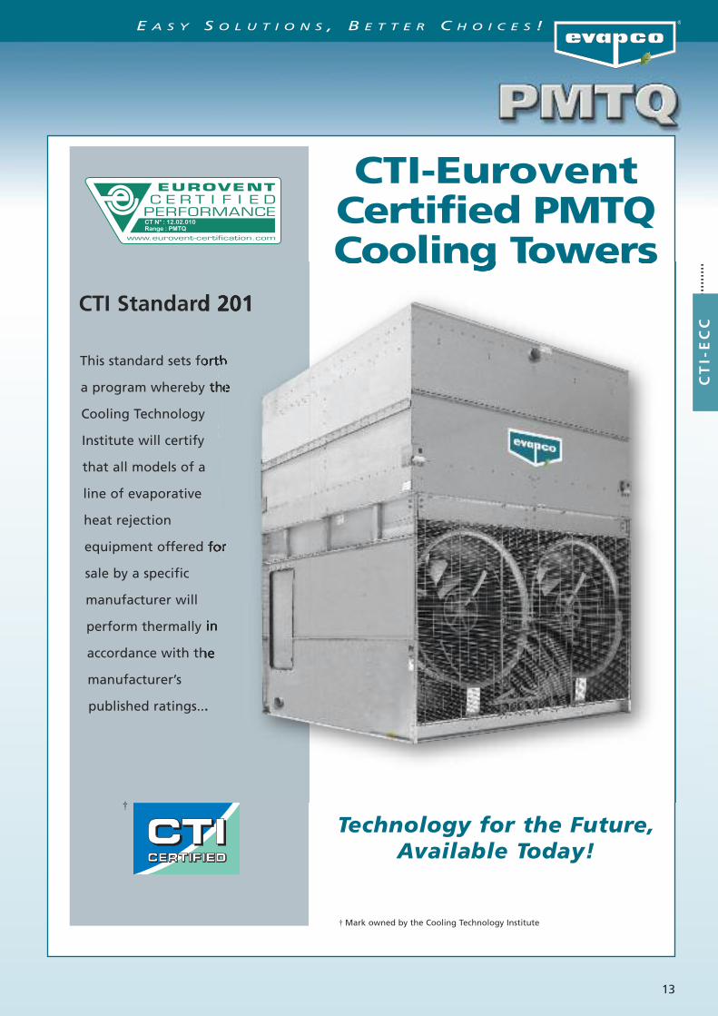
CTI-EuroventCertified PMTQCooling Towers
Technology for the Future,Available Today!
CTI Standard 201
This standard sets forth
a program whereby the
Cooling Technology
Institute will certify
that all models of a
line of evaporative
heat rejection
equipment offered for
sale by a specific
manufacturer will
perform thermally in
accordance with the
manufacturer’s
published ratings...
† Mark owned by the Cooling Technology Institute
CT
I-E
CC
E A S Y S O L U T I O N S , B E T T E R C H O I C E S !
†
CT N° : 12.02.010Range : PMTQ

14
What is CTI?
Cooling Technology InstituteThe Cooling Technology Institute is an organizationheadquartered in the United States with over 400 membercompanies from around the globe. CTI membership iscomposed of manufacturers, suppliers, owner operators, andtest agencies from over 40 countries. In 2008 CTI certified morethan 5000 Evaporative Heat Transfer Systems (EHTS) from 49product lines of 24 participants.
CTI’s Mission and ObjectivesThis can be best explained by the CTI’s published Missionstatement and Objectives revised in December 2003 andpublished on their website www.cti.org.
CTI Mission StatementTo advocate and promote the use of environmentallyresponsible Evaporative Heat Transfer Systems (EHTS)for the benefit of the public by encouraging:
• Education• Research• Standards Development and Verification• Government Relations• Technical Information Exchange
CTI Objectives• Maintain and expand a broad base membership of
individuals and organizations interested in Evaporative Heat Transfer Systems (EHTS).
• Identify and address emerging and evolving issues concerning EHTS.
• Encourage and support educational programs invarious formats to enhance the capabilities andcompetence of the industry to realize the maximum benefit of EHTS.
• Encourage and support cooperative research to improve EHTS technology and efficiency for thelong-term benefit of the environment.
• Assure acceptable minimum quality levels andperformance of EHTS and their components byestablishing standard specifications, guidelines, and certification programs.
• Establish standard testing and performance analysis systems and procedures for EHTS.
• Communicate with and influence governmentalentities regarding the environmentally responsible technologies, benefits, and issues associated with EHTS.
• Encourage and support forums and methods forexchanging technical information on EHTS.
Benefits to the End UserCTI defines an independent testing certification programthat is specifiable, enforceable and available to allequipment manufacturer’s. End users that purchase CTIcertified products are assured that those products willperform thermally as specified.Additionally CTI certification is the first step for theGreen Building Concept in Europe:
• LEED - Leadership in Energy and Environmental Design
• Best Available Practice• Green Building Rating System
Thermal Performance GuaranteeIn addition to the CTI Certification, Evapco unequivocallyguarantees the Thermal Performance of ALL EvapcoEquipment. Every unit order is confirmed with asubmittal package that includes an Evapco ThermalPerformance Guarantee Certificate.
In its continuing commitment to be the leaders in evaporative cooling equipment design andservices, EVAPCO PMTQ Cooling Towers are now Independently Certified by CTI, to perform
thermally in accordance with the published data.
CTI CODE TOWERStandard SpecificationsAcceptance Test CodeforWater Cooling Towers
CTI Code ATC-105
COOLING TECHNOLOGYINSTITUTE
Standard for Thermal Performance
Certificationof
Evaporative Heat Rejection
Equipment
STD 201
COOLING TECHNOLOGY
INSTITUTE
C T I C E R T I F I C A T I O N
CTI-ECC
E A S Y S O L U T I O N S , B E T T E R C H O I C E S !

15
CTI Certification Program
CTI Certification Process• Submit Application for Certification• CTI completes a technical review of the productline submitted
• CTI performs an initial qualification test in alaboratory on a specified model number
• CTI issues an Approval Letter with Validation Number if test is passed. Letter is also distributedto all members of CTI to inform everyone that asuccessfull certification has been completed.The Certification Validation Number assigned should be fixed to each tower sold and displayed inall catalogs and other literature
• Product Line must undergo an Annual Reverification Test - Different model number is selected every year
• More details can be found on the CTI website www.cti.org
CTI Certification Test Parameters• Entering Wet Bulb temperature - 12.8°C to 32.2°C• Cooling Range - Minimum of 2.2°C• Cooling Approach - Minimum of 2.8°C• Process Fluid Temperature - Maximum of 51.7°C• Barometric Pressure - 91.4 to 105 kPa• More details can be found on the CTI websitewww.cti.org
CTI Certification Limitations• Specific manufacturer’s product line name and model numbers
• Applicable only to product lines and model numbers submitted
• Multiple cell model numbers are allowed if theairflow is not affected or the configuration impact is included in the unit rating
• Optional accessories are allowed if the airflow is not affected or the accessory impact is accounted for in the rating
• More details can be found on the CTI websitewww.cti.org
Evapco Europe CTI Certified PMTQ Product LinePMTQ Line of CTI Certified Cooling Towers• CTI Certification Validation Number 10-13-09• Includes optional remote sump• Includes use of straight discharge hoods• Includes the use of platform and ladder for access• evapSelect Technical data sheet will state“CTI-ECC Certified Cooling Tower”
• Unit will receive a CTI and ECC Certified Shield located near the nameplate
† Mark owned by the Cooling Technology Institute
C T I C E R T I F I C A T I O N
Note
All CTI Certified Product Lines of all manufacturerswith CTI certified products can be found on thewebsite: http://www.cti.org/certification.shtml
CTI-ECC
E A S Y S O L U T I O N S , B E T T E R C H O I C E S !
†

16
E A S Y S O L U T I O N S , B E T T E R C H O I C E S !C
TI-
EC
C EUROVENT – CTI cooperation
EUROVENT AssociationInitially founded in 1958EUROVENT Associationrepresents the Europeanrefrigeration, air conditioning,air handling, heating and ventilation industry and tradeassociations from European and non-European countries.Over 1000 companies in 13 European countries,employing 150000 employees who jointly generate morethan € 25 to 30 billion of annual output are member ofthis organization.
EUROVENT missionEUROVENT represents, promotes and defends the industryto relevant national and international bodies andcooperates with other European umbrella associations.Over the years EUROVENT has become a well-known andrespected stakeholder in all industry related matters and, inparticular, in climate change and energy efficiency. EUROVENT develops product certification programs for theentire industry through the EUROVENT CertificationCompany.
EUROVENT CertificationThe main objective of theEUROVENT CertificationCompany (ECC) is tocertify cooling equipment(and/or components)
independently from EUROVENT Association. With acommon set of well-defined procedures and criteria forthe rating of products, comparison of productperformance ensures a healthy and solid competitionon a market open to all manufacturers. When amanufacturer participates in a certification program, hehas to present its list of models or model rangestogether with their performance data. The files areevaluated by the ECC Certification and a predefinednumber of units are selected for testing by independentlaboratories. If the results comply with the relevantstandards, the submitted models or ranges will be listedin the EUROVENT Certification Online Directory. Modelsare subject to regular random testing to verifycompliance with catalogue data.
BenefitsThe Certification Mark guarantees specifying engineers,installers and end users that the products marketed by aparticipant have been submitted to independent testingand that they have been accurately rated. Through specification of certified products, theengineer's tasks become easier, since there is no need tocarry out detailed comparison and performance testing.
In 2007 Evapco launched the initiative to create the “European Chapter” of CTI.At the start of this initiative, Eurovent and CTI established a “Memorandum of Understanding”.Since then the “Operational Manual for Certification of Cooling Towers” and the “EuroventRating Standard for Cooling Towers” were written. Both documents are strongly tied to theCTI documents STD 201 and ATC 105. A common “CTI-EUROVENT” Certification program hasbecome the European Standard for independent thermal performance rating of cooling towers.
All Evapco CTI Certified cooling towers will be CTI-ECC certified as from February 2012.
C T I - E U R O V E N T C E R T I F I C A T I O N
CT N° : 12.02.010Range : PMTQ

17
ThermalPerformance
EngineeringData
& Dimensions
ENGINEERING
E A S Y S O L U T I O N S , B E T T E R C H O I C E S !
18
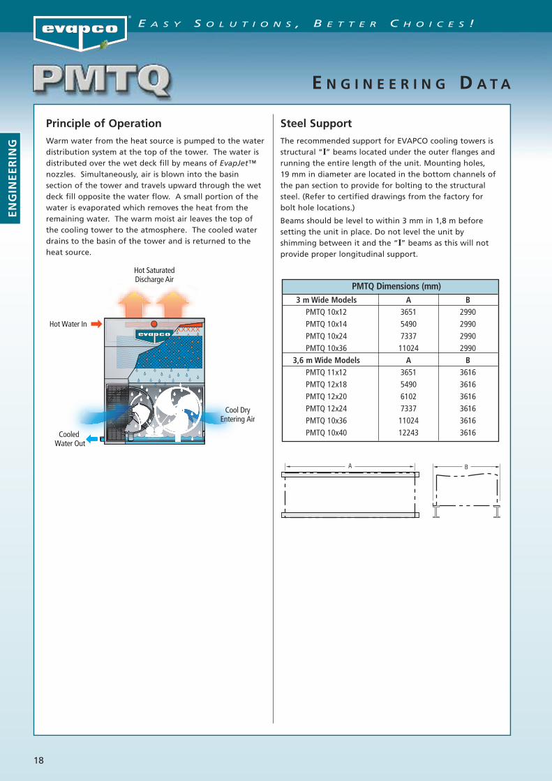
Principle of Operation
Warm water from the heat source is pumped to the waterdistribution system at the top of the tower. The water isdistributed over the wet deck fill by means of EvapJet™nozzles. Simultaneously, air is blown into the basinsection of the tower and travels upward through the wetdeck fill opposite the water flow. A small portion of thewater is evaporated which removes the heat from theremaining water. The warm moist air leaves the top ofthe cooling tower to the atmosphere. The cooled waterdrains to the basin of the tower and is returned to theheat source.
Steel Support
The recommended support for EVAPCO cooling towers isstructural “I” beams located under the outer flanges andrunning the entire length of the unit. Mounting holes,19 mm in diameter are located in the bottom channels ofthe pan section to provide for bolting to the structuralsteel. (Refer to certified drawings from the factory forbolt hole locations.)
Beams should be level to within 3 mm in 1,8 m beforesetting the unit in place. Do not level the unit byshimming between it and the “I” beams as this will notprovide proper longitudinal support.
E N G I N E E R I N G D A T A
Hot Water In
Cooled Water Out
Hot SaturatedDischarge Air
ooledled O
Cool DryEntering Air
ENGINEERING
E A S Y S O L U T I O N S , B E T T E R C H O I C E S !
PMTQ Dimensions (mm)3 m Wide Models A B
PMTQ 10x12 3651 2990PMTQ 10x14 5490 2990PMTQ 10x24 7337 2990PMTQ 10x36 11024 2990
3,6 m Wide Models A BPMTQ 11x12 3651 3616PMTQ 12x18 5490 3616PMTQ 12x20 6102 3616PMTQ 12x24 7337 3616PMTQ 10x36 11024 3616PMTQ 10x40 12243 3616
A B

19
T H E R M A L P E R F O R M A N C E
Selection Procedure
MODELS PMTQ 10112 THRU 10918
Thermal performance certified by theCooling Technology Institute (CTI)
and Eurovent Certification Company (ECC)in accordance with CTI Standard 201
† Mark Owned by the Cooling Technology Institute.
Cooling Capacity in l/sTEMP °CEWT 32 36 32 36 32 36 32 37 35 40
MOTOR LWT 27 26 27 26 27 26 27 27 30 30MODEL NO. kW WB 19 19 20 20 21 21 22 22 24 24
PMTQ 10112 (2) 4 57,2 29,9 52,5 26,3 46,8 22,5 40,6 24,2 54,9 34,2PMTQ 10212 (2) 4 64,5 36,5 59,7 33,1 54,0 29,5 47,6 31,2 62,1 40,9PMTQ 10312 (2) 5,5 67,0 36,7 61,7 32,8 55,5 28,8 48,6 30,7 64,4 41,4PMTQ 10412 (2) 4 67,6 41,5 63,0 38,3 57,7 34,8 51,7 36,4 65,3 45,5PMTQ 10512 (2) 5,5 74,2 43,4 69,0 39,6 62,7 35,5 55,7 37,4 71,6 48,4PMTQ 10612 (2) 5,5 77,0 47,9 71,9 44,3 65,9 40,4 59,3 42,3 74,5 52,4PMTQ 10712 (2) 7,5 84,1 52,7 78,6 48,9 72,1 44,6 64,9 46,6 81,4 57,6PMTQ 10812 (2) 11 91,5 56,0 85,4 51,5 78,2 46,4 70,1 48,9 88,5 61,6PMTQ 10912 (2) 11 94,4 59,6 88,2 55,4 80,9 50,7 73,0 52,9 91,3 64,9
PMTQ 10118 (3) 4 86,2 44,9 79,0 39,6 70,5 33,8 61,1 36,4 82,6 51,4PMTQ 10218 (3) 4 97,1 55,0 89,9 49,9 81,3 44,4 71,6 47,0 93,6 61,5PMTQ 10318 (3) 5,5 101,0 55,2 93,0 49,4 83,5 43,3 73,1 46,1 97,0 62,3PMTQ 10418 (3) 4 101,8 62,5 95,0 57,6 86,9 52,4 77,9 54,9 98,4 68,5PMTQ 10518 (3) 5,5 111,8 65,4 103,9 59,6 94,5 53,4 83,9 56,3 107,9 72,8PMTQ 10618 (3) 5,5 116,0 72,1 108,4 66,7 99,3 60,8 89,3 63,7 112,2 79,0PMTQ 10718 (3) 7,5 126,8 79,4 118,4 73,6 108,6 67,2 97,8 70,2 122,6 86,8PMTQ 10818 (3) 11 137,9 84,4 128,8 77,6 117,8 69,9 105,7 73,6 133,3 92,8PMTQ 10918 (3) 11 142,3 89,8 133,0 83,4 122,0 76,4 110,0 79,7 137,7 97,8
To Make a Selection:Locate the column with the desired operating temperature conditions. Read down the column until you find the l/s equal to orgreater than the flow required. Read horizontally to the left to find the model number of the unit that will perform the duty.
Note: For alternate selections and conditions other than those stated, consult your selection program or local EVAPCO representative.
†
Cooling Capacity in l/sTEMP °CEWT 35 40 35 37 40 42 36 37 41 42
MOTOR LWT 30 30 30 32 30 32 31 32 31 32MODEL NO. kW WB 25 25 26 26 26 26 27 27 27 27
PMTQ 10112 (2) 4 48,8 30,3 41,5 60,9 25,5 38,8 43,9 54,4 27,7 34,9PMTQ 10212 (2) 4 55,9 37,0 48,5 68,1 32,4 45,7 50,9 61,7 34,3 41,6PMTQ 10312 (2) 5,5 57,6 37,1 49,5 71,1 32,0 46,5 52,1 63,9 34,2 42,2PMTQ 10412 (2) 4 59,5 41,9 52,5 71,1 37,6 50,0 54,8 64,9 39,4 46,1PMTQ 10512 (2) 5,5 64,8 43,9 56,7 78,2 38,8 53,6 59,3 71,2 40,9 49,2PMTQ 10612 (2) 5,5 67,9 48,3 60,2 80,9 43,6 57,4 62,7 74,0 45,5 53,1PMTQ 10712 (2) 7,5 74,2 53,2 65,9 88,4 48,0 62,9 68,6 80,8 50,2 58,3PMTQ 10812 (2) 11 80,6 56,6 71,2 96,1 50,5 67,7 74,3 87,9 53,0 62,5PMTQ 10912 (2) 11 83,4 60,1 74,0 99,2 54,5 70,7 77,1 90,8 56,8 65,7
PMTQ 10118 (3) 4 73,5 45,6 62,4 91,7 38,4 58,4 66,1 82,0 41,6 52,5PMTQ 10218 (3) 4 84,3 55,7 73,0 102,6 48,8 68,8 76,7 92,9 51,7 62,6PMTQ 10318 (3) 5,5 86,7 55,9 74,6 107,2 48,2 70,1 78,5 96,3 51,5 63,5PMTQ 10418 (3) 4 89,6 63,1 79,1 107,1 56,6 75,3 82,6 97,8 59,3 69,5PMTQ 10518 (3) 5,5 97,7 66,2 85,4 117,8 58,4 80,8 89,4 107,2 61,6 74,0PMTQ 10618 (3) 5,5 102,3 72,8 90,7 122,0 65,6 86,5 94,5 111,5 68,6 80,1PMTQ 10718 (3) 7,5 111,9 80,2 99,2 133,3 72,4 94,7 103,4 121,8 75,6 87,9PMTQ 10818 (3) 11 121,5 85,3 107,3 144,9 76,1 102,1 112,0 132,5 79,9 94,2PMTQ 10918 (3) 11 125,7 90,6 111,6 149,6 82,1 106,6 116,2 136,8 85,7 99,0
ENGINEERING
E A S Y S O L U T I O N S , B E T T E R C H O I C E S !
CT N° : 12.02.010Range : PMTQ

20
Selection Procedure (continued)
MODELS PMTQ 10124 THRU 10936
† Mark Owned by the Cooling Technology Institute.
Cooling Capacity in l/sTEMP °CEWT 32 36 32 36 32 36 32 37 35 40
MOTOR LWT 27 26 27 26 27 26 27 27 30 30MODEL NO. kW WB 19 19 20 20 21 21 22 22 24 24
PMTQ 10124 (4) 4 114,5 59,7 104,9 52,7 93,7 44,9 81,2 48,4 109,7 68,4PMTQ 10224 (4) 4 129,0 73,1 119,4 66,3 107,9 59,0 95,1 62,4 124,2 81,7PMTQ 10324 (4) 5,5 134,1 73,3 123,5 65,7 110,9 57,6 97,1 61,3 128,8 82,8PMTQ 10424 (4) 4 135,2 82,9 126,1 76,5 115,4 69,6 103,4 72,9 130,7 91,0PMTQ 10524 (4) 5,5 148,4 86,9 138,0 79,1 125,4 70,9 111,4 74,7 143,3 96,7PMTQ 10624 (4) 5,5 154,0 95,7 143,8 88,6 131,8 80,8 118,6 84,5 148,9 104,8PMTQ 10724 (4) 7,5 168,2 105,4 157,1 97,7 144,1 89,2 129,8 93,2 162,7 115,2PMTQ 10824 (4) 11 182,9 112,0 170,8 102,9 156,3 92,8 140,2 97,7 176,9 123,2PMTQ 10924 (4) 11 188,8 119,1 176,4 110,7 161,8 101,3 146,0 105,7 182,7 129,7
PMTQ 10136 (6) 4 171,7 89,6 157,4 79,0 140,5 67,4 121,8 72,6 164,6 102,5PMTQ 10236 (6) 4 193,4 109,6 179,1 99,4 161,9 88,5 142,7 93,6 186,3 122,6PMTQ 10336 (6) 5,5 201,1 110,0 185,2 98,5 166,4 86,4 145,7 92,0 193,3 124,2PMTQ 10436 (6) 4 202,7 124,4 189,1 114,8 173,1 104,5 155,1 109,3 196,0 136,5PMTQ 10536 (6) 5,5 222,6 130,3 206,9 118,7 188,1 106,4 167,2 112,1 214,9 145,1PMTQ 10636 (6) 5,5 231,0 143,6 215,7 132,9 197,6 121,2 177,9 126,8 223,4 157,3PMTQ 10736 (6) 7,5 252,4 158,1 235,7 146,6 216,2 133,8 194,7 139,8 244,1 172,8PMTQ 10836 (6) 11 274,4 168,0 256,2 154,4 234,5 139,3 210,3 146,6 265,4 184,8PMTQ 10936 (6) 11 283,3 178,7 264,6 166,1 242,8 152,0 218,9 158,6 274,0 194,6
To Make a Selection:Locate the column with the desired operating temperature conditions. Read down the column until you find the l/s equal to orgreater than the flow required. Read horizontally to the left to find the model number of the unit that will perform the duty.
Note: For alternate selections and conditions other than those stated, consult your selection program or local EVAPCO representative.
Cooling Capacity in l/sTEMP °CEWT 35 40 35 37 40 42 36 37 41 42
MOTOR LWT 30 30 30 32 30 32 31 32 31 32MODEL NO. kW WB 25 25 26 26 26 26 27 27 27 27
PMTQ 10124 (4) 4 97,6 60,6 83,0 121,7 51,1 77,6 87,7 108,9 55,4 69,8PMTQ 10224 (4) 4 111,9 74,0 96,9 136,2 64,8 91,3 101,9 123,3 68,7 83,1PMTQ 10324 (4) 5,5 115,1 74,3 99,0 142,3 64,1 93,0 104,2 127,9 68,5 84,4PMTQ 10424 (4) 4 119,0 83,8 105,0 142,2 75,2 99,9 109,7 129,8 78,7 92,3PMTQ 10524 (4) 5,5 129,6 87,9 113,3 156,4 77,5 107,3 118,7 142,3 81,8 98,3PMTQ 10624 (4) 5,5 135,8 96,7 120,3 161,9 87,1 114,8 125,4 148,0 91,1 106,3PMTQ 10724 (4) 7,5 148,5 106,4 131,7 176,8 96,1 125,7 137,2 161,7 100,4 116,7PMTQ 10824 (4) 11 161,2 113,2 142,4 192,2 101,1 135,5 148,6 175,8 106,1 125,0PMTQ 10924 (4) 11 166,7 120,2 148,1 198,5 108,9 141,4 154,2 181,5 113,7 131,4
PMTQ 10136 (6) 4 146,4 90,8 124,4 182,6 76,6 116,4 131,6 163,3 83,1 104,7PMTQ 10236 (6) 4 167,8 110,9 145,4 204,4 97,3 137,0 152,8 185,0 103,0 124,7PMTQ 10336 (6) 5,5 172,7 111,4 148,5 213,4 96,1 139,6 156,4 191,8 102,7 126,5PMTQ 10436 (6) 4 178,5 125,7 157,5 213,3 112,8 149,9 164,5 194,7 118,1 138,4PMTQ 10536 (6) 5,5 194,4 131,8 170,0 234,6 116,3 160,9 178,0 213,5 122,7 147,5PMTQ 10636 (6) 5,5 203,7 145,0 180,5 242,8 130,7 172,2 188,1 222,0 136,6 159,4PMTQ 10736 (6) 7,5 222,7 159,6 197,6 265,3 144,1 188,6 205,9 242,5 150,6 175,0PMTQ 10836 (6) 11 241,8 169,8 213,6 288,4 151,6 203,2 222,9 263,7 159,1 187,5PMTQ 10936 (6) 11 250,1 180,3 222,1 297,7 163,4 212,2 231,3 272,3 170,5 197,1
T H E R M A L P E R F O R M A N C E
ENGINEERING
E A S Y S O L U T I O N S , B E T T E R C H O I C E S !
Thermal performance certified by theCooling Technology Institute (CTI)
and Eurovent Certification Company (ECC)in accordance with CTI Standard 201
†
CT N° : 12.02.010Range : PMTQ

21
Selection Procedure (continued)
MODELS PMTQ 12112 THRU 12918
† Mark Owned by the Cooling Technology Institute.
Cooling Capacity in l/sTEMP °CEWT 32 36 32 36 32 36 32 37 35 40
MOTOR LWT 27 26 27 26 27 26 27 27 30 30MODEL NO. kW WB 19 19 20 20 21 21 22 22 24 24
PMTQ 12112 (2) 4 65,3 33,4 59,9 29,0 53,2 25,8 45,9 26,8 62,6 38,3PMTQ 12212 (2) 4 74,1 41,5 68,6 37,5 61,8 33,4 54,2 35,4 71,3 46,5PMTQ 12312 (2) 5,5 76,9 41,4 70,7 37,0 63,4 32,0 55,3 34,6 73,8 46,9PMTQ 12412 (2) 4 78,1 47,6 72,8 43,9 66,5 39,9 59,5 41,8 75,4 52,3PMTQ 12512 (2) 5,5 85,7 49,6 79,5 45,1 72,1 40,2 63,9 42,6 82,6 55,2PMTQ 12612 (2) 5,5 89,2 55,2 83,2 51,1 76,2 46,5 68,6 48,6 86,2 60,5PMTQ 12712 (2) 7,5 97,6 61,0 91,2 56,4 83,6 51,5 75,3 53,8 94,4 66,7PMTQ 12812 (2) 11 106,7 64,8 99,6 59,6 91,0 53,6 81,5 56,4 103,2 71,5PMTQ 12912 (2) 11 110,2 69,4 103,0 64,4 94,4 58,9 85,1 61,5 106,6 75,6
PMTQ 12118 (3) 4 98,3 50,2 90,1 43,7 80,1 39,1 69,1 40,3 94,2 57,6PMTQ 12218 (3) 4 111,6 62,5 103,3 56,5 93,1 50,2 81,6 53,2 107,4 70,0PMTQ 12318 (3) 5,5 115,9 62,3 106,5 55,6 95,4 48,1 83,2 52,0 111,2 70,6PMTQ 12418 (3) 4 117,6 71,7 109,7 66,2 100,2 60,0 89,7 63,0 113,7 78,8PMTQ 12518 (3) 5,5 129,1 74,6 119,8 67,9 108,7 60,6 96,3 64,1 124,5 83,2PMTQ 12618 (3) 5,5 134,4 83,1 125,4 76,9 114,9 70,0 103,3 73,2 129,9 91,1PMTQ 12718 (3) 7,5 147,1 91,9 137,4 85,0 126,0 77,6 113,4 81,1 142,3 100,5PMTQ 12818 (3) 11 160,9 97,7 150,1 89,8 137,2 80,7 122,8 84,9 155,6 107,7PMTQ 12918 (3) 11 166,1 104,6 155,2 97,1 142,3 88,8 128,3 92,7 160,7 114,0
To Make a Selection:Locate the column with the desired operating temperature conditions. Read down the column until you find the l/s equal to orgreater than the flow required. Read horizontally to the left to find the model number of the unit that will perform the duty.
Note: For alternate selections and conditions other than those stated, consult your selection program or local EVAPCO representative.
Cooling Capacity in l/sTEMP °CEWT 35 40 35 37 40 42 36 37 41 42
MOTOR LWT 30 30 30 32 30 32 31 32 31 32MODEL NO. kW WB 25 25 26 26 26 26 27 27 27 27
PMTQ 12112 (2) 4 55,4 34,0 46,9 69,6 28,2 43,9 49,7 62,1 30,5 39,1PMTQ 12212 (2) 4 64,0 42,0 55,2 78,4 36,7 52,1 58,2 70,8 38,9 47,2PMTQ 12312 (2) 5,5 65,8 42,1 56,4 81,7 36,1 53,0 59,6 73,2 38,5 47,8PMTQ 12412 (2) 4 68,7 48,1 60,5 82,1 43,2 57,5 63,2 75,0 45,2 53,1PMTQ 12512 (2) 5,5 74,6 50,2 65,0 90,3 44,2 61,6 68,3 82,0 46,6 56,1PMTQ 12612 (2) 5,5 78,6 55,7 69,6 93,7 50,2 66,3 72,5 85,7 52,5 61,3PMTQ 12712 (2) 7,5 86,2 61,5 76,4 102,6 55,5 72,9 79,6 93,8 58,0 67,6PMTQ 12812 (2) 11 94,0 65,5 82,8 112,2 58,4 78,7 86,5 102,6 61,4 72,5PMTQ 12912 (2) 11 97,3 70,1 86,4 115,8 63,4 82,5 90,0 105,9 66,2 76,6
PMTQ 12118 (3) 4 83,4 51,1 70,6 104,8 42,4 66,1 74,9 93,5 45,8 58,8PMTQ 12218 (3) 4 96,4 63,3 83,1 118,1 55,3 78,4 87,6 106,7 58,5 71,1PMTQ 12318 (3) 5,5 99,2 63,3 84,9 123,0 54,3 79,8 89,7 110,3 57,9 71,9PMTQ 12418 (3) 4 103,5 72,4 91,1 123,8 65,0 86,6 95,1 113,0 68,1 79,9PMTQ 12518 (3) 5,5 112,4 75,5 97,9 136,1 66,5 92,7 102,8 123,6 70,2 84,5PMTQ 12618 (3) 5,5 118,4 83,9 104,9 141,3 75,6 99,9 109,3 129,1 79,1 92,4PMTQ 12718 (3) 7,5 129,8 92,7 115,1 154,7 83,6 109,8 119,9 141,4 87,4 101,9PMTQ 12818 (3) 11 141,6 98,7 124,8 169,1 88,0 118,6 130,4 154,6 92,5 109,3PMTQ 12918 (3) 11 146,6 105,6 130,2 174,6 95,5 124,3 135,6 159,7 99,7 115,5
T H E R M A L P E R F O R M A N C E
ENGINEERING
E A S Y S O L U T I O N S , B E T T E R C H O I C E S !
Thermal performance certified by theCooling Technology Institute (CTI)
and Eurovent Certification Company (ECC)in accordance with CTI Standard 201
†
CT N° : 12.02.010Range : PMTQ

22
Selection Procedure (continued)
MODELS PMTQ 12120 THRU 12924
† Mark Owned by the Cooling Technology Institute.
Cooling Capacity in l/sTEMP °CEWT 32 36 32 36 32 36 32 37 35 40
MOTOR LWT 27 26 27 26 27 26 27 27 30 30MODEL NO. kW WB 19 19 20 20 21 21 22 22 24 24
PMTQ 12120 (3) 4 99,4 48,2 90,6 43,3 80,1 45,3 68,7 44,3 94,9 56,8PMTQ 12220 (3) 4 114,0 62,5 105,0 56,6 94,2 49,7 82,3 52,9 109,5 70,4PMTQ 12320 (3) 5,5 117,7 61,5 107,9 54,4 96,3 46,3 83,6 50,0 112,8 70,5PMTQ 12420 (3) 4 121,2 73,3 112,9 67,4 102,9 61,1 91,8 64,0 117,1 80,6PMTQ 12520 (3) 5,5 132,4 75,2 122,6 68,2 110,9 60,7 97,8 64,2 127,6 84,1PMTQ 12620 (3) 5,5 138,7 85,2 129,4 78,6 118,4 71,6 106,1 74,9 134,1 93,4PMTQ 12720 (3) 7,5 152,1 94,3 142,0 87,3 130,1 79,4 117,0 83,1 147,1 103,3PMTQ 12820 (3) 11 166,6 99,8 155,2 91,1 141,6 81,8 126,3 86,3 160,9 110,3PMTQ 12920 (3) 11 172,2 107,9 160,8 100,0 147,5 91,3 132,9 95,4 166,5 117,9
PMTQ 12124 (4) 4 130,6 66,8 119,7 58,1 106,4 51,7 91,8 53,6 125,1 76,6PMTQ 12224 (4) 4 148,2 83,0 137,1 75,1 123,6 66,7 108,4 70,7 142,6 92,9PMTQ 12324 (4) 5,5 153,9 82,9 141,4 73,9 126,8 63,9 110,6 69,1 147,6 93,8PMTQ 12424 (4) 4 156,1 95,2 145,6 87,9 133,1 79,7 119,1 83,6 150,9 104,7PMTQ 12524 (4) 5,5 171,4 99,1 159,0 90,2 144,3 80,5 127,8 85,2 165,2 110,5PMTQ 12624 (4) 5,5 178,3 110,3 166,5 102,1 152,4 92,9 137,1 97,2 172,4 121,0PMTQ 12724 (4) 7,5 195,3 121,9 182,4 112,9 167,2 103,1 150,5 107,7 188,9 133,4PMTQ 12824 (4) 11 213,4 129,7 199,2 119,2 182,1 107,1 163,0 112,7 206,4 143,0PMTQ 12924 (4) 11 220,4 138,8 205,9 128,8 188,9 117,8 170,3 123,0 213,2 151,2
To Make a Selection:Locate the column with the desired operating temperature conditions. Read down the column until you find the l/s equal to orgreater than the flow required. Read horizontally to the left to find the model number of the unit that will perform the duty.
Note: For alternate selections and conditions other than those stated, consult your selection program or local EVAPCO representative.
Cooling Capacity in l/sTEMP °CEWT 35 40 35 37 40 42 36 37 41 42
MOTOR LWT 30 30 30 32 30 32 31 32 31 32MODEL NO. kW WB 25 25 26 26 26 26 27 27 27 27
PMTQ 12120 (3) 4 83,7 49,0 70,3 106,0 43,6 65,2 74,7 94,1 44,3 58,1PMTQ 12220 (3) 4 97,9 63,3 83,9 120,7 55,2 78,9 88,5 108,7 58,7 71,7PMTQ 12320 (3) 5,5 100,4 62,4 85,4 125,1 52,7 79,8 90,2 111,9 57,2 71,9PMTQ 12420 (3) 4 106,2 74,0 93,3 127,6 66,2 88,7 97,6 116,4 69,4 81,7PMTQ 12520 (3) 5,5 115,0 76,1 99,6 139,9 66,7 93,9 104,6 126,7 70,7 85,5PMTQ 12620 (3) 5,5 122,1 86,1 107,8 145,9 77,2 102,6 112,6 133,2 80,9 94,7PMTQ 12720 (3) 7,5 134,1 95,2 118,8 159,9 85,8 113,3 123,8 146,2 89,7 104,7PMTQ 12820 (3) 11 146,2 100,9 128,4 175,3 89,3 121,8 134,2 159,9 94,1 112,0PMTQ 12920 (3) 11 152,0 108,9 134,8 181,0 98,4 128,7 140,5 165,5 102,8 119,4
PMTQ 12124 (4) 4 110,8 68,0 93,8 139,2 56,4 87,8 99,5 124,2 61,0 78,2PMTQ 12224 (4) 4 128,1 84,1 110,4 156,8 73,5 104,2 116,4 141,6 77,8 94,5PMTQ 12324 (4) 5,5 131,7 84,1 112,7 163,3 72,1 106,0 119,2 146,5 76,9 95,5PMTQ 12424 (4) 4 137,4 96,2 120,9 164,3 86,4 115,0 126,3 149,9 90,4 106,1PMTQ 12524 (4) 5,5 149,3 100,3 130,0 180,7 88,4 123,1 136,6 164,1 93,2 112,3PMTQ 12624 (4) 5,5 157,2 111,4 139,2 187,5 100,3 132,6 145,1 171,4 105,0 122,6PMTQ 12724 (4) 7,5 172,3 123,1 152,7 205,3 111,0 145,8 159,2 187,7 116,0 135,2PMTQ 12824 (4) 11 187,9 131,1 165,6 224,4 116,8 157,5 173,0 205,1 122,8 145,1PMTQ 12924 (4) 11 194,6 140,1 172,8 231,7 126,7 165,0 179,9 211,9 132,3 153,2
T H E R M A L P E R F O R M A N C E
ENGINEERING
E A S Y S O L U T I O N S , B E T T E R C H O I C E S !
Thermal performance certified by theCooling Technology Institute (CTI)
and Eurovent Certification Company (ECC)in accordance with CTI Standard 201
†
CT N° : 12.02.010Range : PMTQ

23
Selection Procedure (continued)
MODELS PMTQ 12136 THRU 12940
† Mark Owned by the Cooling Technology Institute.
Cooling Capacity in l/sTEMP °CEWT 32 36 32 36 32 36 32 37 35 40
MOTOR LWT 27 26 27 26 27 26 27 27 30 30MODEL NO. kW WB 19 19 20 20 21 21 22 22 24 24
PMTQ 12136 (6) 4 195,9 100,1 179,6 87,1 159,7 77,5 137,7 80,4 187,7 114,9PMTQ 12236 (6) 4 222,3 124,5 205,7 112,6 185,4 100,1 162,6 106,1 214,0 139,4PMTQ 12336 (6) 5,5 230,8 124,3 212,1 110,9 190,1 95,9 165,8 103,7 221,5 140,7PMTQ 12436 (6) 4 234,2 142,8 218,4 131,8 199,6 119,6 178,6 125,4 226,3 157,0PMTQ 12536 (6) 5,5 257,1 148,7 238,5 135,3 216,4 120,7 191,7 127,8 247,9 165,7PMTQ 12636 (6) 5,5 267,5 165,5 249,7 153,2 228,7 139,4 205,7 145,8 258,7 181,5PMTQ 12736 (6) 7,5 292,9 182,9 273,6 169,3 250,8 154,6 225,8 161,5 283,3 200,1PMTQ 12836 (6) 11 320,2 194,5 298,8 178,8 273,1 160,7 244,5 169,1 309,6 214,5PMTQ 12936 (6) 11 330,6 208,3 308,9 193,2 283,3 176,8 255,4 184,5 319,8 226,9
PMTQ 12140 (6) 4 198,8 96,4 181,1 86,6 160,3 90,6 137,3 88,6 189,9 113,7PMTQ 12240 (6) 4 228,0 124,9 210,0 113,1 188,4 99,4 164,6 105,7 219,0 140,7PMTQ 12340 (6) 5,5 235,3 123,0 215,8 108,8 192,7 92,7 167,2 100,0 225,7 140,9PMTQ 12440 (6) 4 242,4 146,5 225,8 134,8 205,7 122,2 183,7 128,1 234,3 161,1PMTQ 12540 (6) 5,5 264,8 150,3 245,2 136,4 221,8 121,4 195,6 128,4 255,2 168,1PMTQ 12640 (6) 5,5 277,4 170,4 258,8 157,2 236,9 143,1 212,2 149,7 268,2 186,9PMTQ 12740 (6) 7,5 304,3 188,6 284,1 174,5 260,2 158,9 234,1 166,2 294,2 206,6PMTQ 12840 (6) 11 333,1 199,6 310,4 182,2 283,1 163,5 252,6 172,6 321,9 220,7PMTQ 12940 (6) 11 344,4 215,8 321,7 200,1 295,0 182,7 265,7 190,8 333,1 235,8
To Make a Selection:Locate the column with the desired operating temperature conditions. Read down the column until you find the l/s equal to orgreater than the flow required. Read horizontally to the left to find the model number of the unit that will perform the duty.
Note: For alternate selections and conditions other than those stated, consult your selection program or local EVAPCO representative.
Cooling Capacity in l/sTEMP °CEWT 35 40 35 37 40 42 36 37 41 42
MOTOR LWT 30 30 30 32 30 32 31 32 31 32MODEL NO. kW WB 25 25 26 26 26 26 27 27 27 27
PMTQ 12136 (6) 4 166,2 102,0 140,6 208,8 84,6 131,7 149,2 186,2 91,4 117,3PMTQ 12236 (6) 4 192,1 126,1 165,6 235,1 110,2 156,2 174,6 212,4 116,6 141,7PMTQ 12336 (6) 5,5 197,5 126,2 169,1 245,0 108,2 159,0 178,8 219,7 115,4 143,3PMTQ 12436 (6) 4 206,1 144,2 181,4 246,4 129,5 172,5 189,5 224,9 135,6 159,2PMTQ 12536 (6) 5,5 223,9 150,5 195,1 271,0 132,6 184,7 204,8 246,1 139,8 168,4PMTQ 12636 (6) 5,5 235,7 167,1 208,8 281,2 150,5 198,9 217,6 257,0 157,4 183,9PMTQ 12736 (6) 7,5 258,5 184,6 229,1 307,9 166,4 218,6 238,8 281,5 174,0 202,8PMTQ 12836 (6) 11 281,9 196,6 248,4 336,6 175,2 236,2 259,6 307,7 184,2 217,6PMTQ 12936 (6) 11 291,9 210,2 259,2 347,5 190,1 247,4 269,9 317,8 198,5 229,8
PMTQ 12140 (6) 4 167,4 98,0 140,6 212,0 87,3 130,5 149,5 188,3 88,5 116,2PMTQ 12240 (6) 4 195,8 126,5 167,9 241,4 110,4 157,8 177,1 217,3 117,3 143,3PMTQ 12340 (6) 5,5 200,7 124,8 170,8 250,2 105,5 159,7 180,5 223,8 114,5 143,9PMTQ 12440 (6) 4 212,5 148,0 186,6 255,2 132,3 177,4 195,2 232,8 138,9 163,4PMTQ 12540 (6) 5,5 229,9 152,1 199,3 279,8 133,4 187,8 209,3 253,3 141,4 171,0PMTQ 12640 (6) 5,5 244,2 172,1 215,6 291,8 154,5 205,2 225,2 266,4 161,7 189,5PMTQ 12740 (6) 7,5 268,2 190,4 237,6 319,9 171,6 226,5 247,6 292,4 179,4 209,4PMTQ 12840 (6) 11 292,4 201,8 256,7 350,5 178,7 243,7 268,5 319,8 188,2 224,0PMTQ 12940 (6) 11 303,9 217,9 269,6 362,0 196,7 257,4 280,9 331,0 205,5 238,9
T H E R M A L P E R F O R M A N C E
ENGINEERING
E A S Y S O L U T I O N S , B E T T E R C H O I C E S !
Thermal performance certified by theCooling Technology Institute (CTI)
and Eurovent Certification Company (ECC)in accordance with CTI Standard 201
†
CT N° : 12.02.010Range : PMTQ

24
MODELS PMTQ 10112 THRU 10918
ENG INEER ING DATA & DIMENS IONS
Engineering Data
Fans Weights (kg) Remote Sump Dimensions (mm) Connections (mm)Model Motor Air Flow Heaviest Operating Weight Water Water Make OverNo. (kW) (m3/s) Shipping Operating Section† (kg) H U J P Inlet Outlet Up Drain Flow
PMTQ 10112 (2) 4 29,4 3.250 5.810 2.015 4.460 4074 1473 197 3870 200 200 50 80 80
PMTQ 10212 (2) 4 28,3 3.475 6.160 2.015 4.810 4378 1778 197 4175 200 200 50 80 80
PMTQ 10312 (2) 5.5 33,6 3.295 5.855 2.060 4.505 4074 1473 197 3870 200 200 50 80 80
PMTQ 10412 (2) 4 27,1 3.675 6.500 2.015 5.155 4683 2083 197 4480 200 200 50 80 80
PMTQ 10512 (2) 5.5 32,4 3.520 6.205 2.060 4.855 4378 1778 197 4175 200 200 50 80 80
PMTQ 10612 (2) 5.5 31,0 3.720 6.545 2.060 5.200 4683 2083 197 4480 200 200 50 80 80
PMTQ 10712 (2) 7.5 34,0 3.740 6.565 2.075 5.215 4683 2083 197 4480 200 200 50 80 80
PMTQ 10812 (2) 11 39,9 3.655 6.340 2.195 4.990 4378 1778 197 4175 200 200 50 80 80
PMTQ 10912 (2) 11 38,3 3.855 6.680 2.195 5.335 4683 2083 197 4480 200 200 50 80 80
PMTQ 10118 (3) 4 44,4 5.095 9.055 3.345 7.005 4074 1473 229 3845 250 250 50 80 80
PMTQ 10218 (3) 4 42,7 5.425 9.570 3.345 7.520 4378 1778 229 4150 250 250 50 80 80
PMTQ 10318 (3) 5.5 50,7 5.165 9.125 3.415 7.075 4074 1473 229 3845 250 250 50 80 80
PMTQ 10418 (3) 4 40,9 5.725 10.090 3.345 8.040 4683 2083 229 4455 250 250 50 80 80
PMTQ 10518 (3) 5.5 48,8 5.500 9.645 3.415 7.595 4378 1778 229 4150 250 250 50 80 80
PMTQ 10618 (3) 5.5 46,8 5.795 10.160 3.415 8.110 4683 2083 229 4455 250 250 50 80 80
PMTQ 10718 (3) 7.5 51,2 5.820 10.185 3.440 8.135 4683 2083 229 4455 250 250 50 80 80
PMTQ 10818 (3) 11 60,2 5.695 9.845 3.615 7.795 4378 1778 229 4150 250 250 50 80 80
PMTQ 10918 (3) 11 57,7 5.995 10.360 3.615 8.310 4683 2083 229 4455 250 250 50 80 80
† Heaviest section is the pan sectionDimensions are subject to change. Do not use for pre-fabrication.
50 MPTMAKE-UP
108464
12801137
299192
J
737
OVERSIZEDACCESS DOOR
200 BFW/GVDOUTLET
80 FPTDRAIN
80 FPTOVERFLOW
P
2600
U
H
508
200 BFW/GVDINLET 1826
3651
21
51
P
250 BFW/GVD INLET2743
5490
21
50 MPTMAKE-UP
108464
12801137
299192
J
737
OVERSIZEDACCESS DOOR
250 BFW/GVDOUTLET
80 FPTDRAIN
80 FPTOVERFLOW
2600
U
H
508
51
PMTQ 10112 thru 10912
PMTQ 10118 thru 10918
ENGINEERING
E A S Y S O L U T I O N S , B E T T E R C H O I C E S !

25
MODELS PMTQ 10124 THRU 10936
ENG INEER ING DATA & DIMENS IONS
Engineering Data
Fans Weights (kg) Remote Sump Dimensions (mm) Connections (mm)Model Motor Air Flow Heaviest Operating Weight Water Water Make OverNo. (kW) (m3/s) Shipping Operating Section† (kg) H U J P Inlet Outlet Up Drain Flow
PMTQ 10124 (4) 4 58,9 6.945 12.060 4.475 9.310 4074 1473 229 3870 (2) 200 250 50 80 80
PMTQ 10224 (4) 4 56,6 7.400 12.760 4.475 10.005 4378 1778 229 4175 (2) 200 250 50 80 80
PMTQ 10324 (4) 5.5 67,3 7.040 12.155 4.570 9.405 4074 1473 229 3870 (2) 200 250 50 80 80
PMTQ 10424 (4) 4 54,3 7.795 13.450 4.475 10.695 4683 2083 229 4480 (2) 200 250 50 80 80
PMTQ 10524 (4) 5.5 64,7 7.495 12.855 4.570 10.100 4378 1778 229 4175 (2) 200 250 50 80 80
PMTQ 10624 (4) 5.5 62,1 7.895 13.545 4.570 10.790 4683 2083 229 4480 (2) 200 250 50 80 80
PMTQ 10724 (4) 7.5 68,0 7.920 13.570 4.600 10.820 4683 2083 229 4480 (2) 200 250 50 80 80
PMTQ 10824 (4) 11 79,9 7.755 13.120 4.835 10.365 4378 1778 229 4175 (2) 200 250 50 80 80
PMTQ 10924 (4) 11 76,6 8.155 13.805 4.835 11.055 4683 2083 229 4480 (2) 200 250 50 80 80
PMTQ 10136 (6) 4 88,4 10.220 17.860 6.520 13.700 4074 1473 229 3870 (3) 200 (2) 250 80 80 80
PMTQ 10236 (6) 4 85,0 10.900 18.905 6.520 14.745 4378 1778 229 4175 (3) 200 (2) 250 80 80 80
PMTQ 10336 (6) 5.5 101,0 10.360 18.000 6.660 13.840 4074 1473 229 3870 (3) 200 (2) 250 80 80 80
PMTQ 10436 (6) 4 81,5 11.500 19.940 6.520 15.780 4683 2083 229 4480 (3) 200 (2) 250 80 80 80
PMTQ 10536 (6) 5.5 97,1 11.040 19.045 6.660 14.885 4378 1778 229 4175 (3) 200 (2) 250 80 80 80
PMTQ 10636 (6) 5.5 93,1 11.640 20.080 6.660 15.920 4683 2083 229 4480 (3) 200 (2) 250 80 80 80
PMTQ 10736 (6) 7.5 102,0 11.685 20.125 6.705 15.965 4683 2083 229 4480 (3) 200 (2) 250 80 80 80
PMTQ 10836 (6) 11 119,8 11.445 19.450 7.060 15.290 4378 1778 229 4175 (3) 200 (2) 250 80 80 80
PMTQ 10936 (6) 11 114,9 12.045 20.485 7.060 16.325 4683 2083 229 4480 (3) 200 (2) 250 80 80 80
† Heaviest section is the pan sectionDimensions are subject to change. Do not use for pre-fabrication.
50 MPTMAKE-UP
108
464
12801137
299192
J
737
OVERSIZEDACCESS DOOR
250 BFW/GVDOUTLET
80 FPTDRAIN
80 FPTOVERFLOW
2600
U
H
508
51
P
(2) 200 BFW/GVD INLET1826
7337
21
80 MPTMAKE-UP
108464
12801137
299192
J
737
OVERSIZEDACCESS DOOR
(2) 250 BFW/GVDOUTLET
80 FPTDRAIN
80 FPTOVERFLOW
P2600
U
H
508
(3) 200 BFW/GVD INLET1826
11024
21 21
51
PMTQ 10124 thru 10921
PMTQ 10136 thru 10936
ENGINEERING
E A S Y S O L U T I O N S , B E T T E R C H O I C E S !

26
MODELS PMTQ 12112 THRU 12918
ENG INEER ING DATA & DIMENS IONS
Engineering Data
Fans Weights (kg) Remote Sump Dimensions (mm) Connections (mm)Model Motor Air Flow Heaviest Operating Weight Water Water Make OverNo. (kW) (m3/s) Shipping Operating Section† (kg) H U J P Inlet Outlet Up Drain Flow
PMTQ 12112 (2) 4 34,0 3.720 6.870 2.330 5.155 4099 1499 197 3896 200 200 50 80 80
PMTQ 12212 (2) 4 32,7 3.975 7.270 2.330 5.560 4404 1803 197 4201 200 200 50 80 80
PMTQ 12312 (2) 5.5 38,9 3.770 6.920 2.380 5.205 4099 1499 197 3896 200 200 50 80 80
PMTQ 12412 (2) 4 31,3 4.210 7.685 2.330 5.975 4709 2108 197 4505 200 200 50 80 80
PMTQ 12512 (2) 5.5 37,4 4.025 7.320 2.380 5.610 4404 1803 197 4201 200 200 50 80 80
PMTQ 12612 (2) 5.5 35,9 4.260 7.735 2.380 6.025 4709 2108 197 4505 200 200 50 80 80
PMTQ 12712 (2) 7.5 39,4 4.275 7.745 2.395 6.035 4709 2108 197 4505 200 200 50 80 80
PMTQ 12812 (2) 11 46,5 4.155 7.455 2.515 5.740 4404 1803 197 4201 200 200 50 80 80
PMTQ 12912 (2) 11 44,6 4.390 7.865 2.515 6.155 4709 2108 197 4505 200 200 50 80 80
PMTQ 12118 (3) 4 51,3 5.755 10.465 3.725 7.860 4099 1499 229 3870 250 250 50 80 80
PMTQ 12218 (3) 4 49,3 6.130 11.060 3.725 8.455 4404 1803 229 4175 250 250 50 80 80
PMTQ 12318 (3) 5.5 58,7 5.825 10.530 3.790 7.930 4099 1499 229 3870 250 250 50 80 80
PMTQ 12418 (3) 4 47,2 6.480 11.675 3.725 9.075 4709 2108 229 4480 250 250 50 80 80
PMTQ 12518 (3) 5.5 56,4 6.195 11.125 3.790 8.525 4404 1803 229 4175 250 250 50 80 80
PMTQ 12618 (3) 5.5 54,1 6.550 11.745 3.790 9.145 4709 2108 229 4480 250 250 50 80 80
PMTQ 12718 (3) 7.5 59,4 6.575 11.765 3.815 9.165 4709 2108 229 4480 250 250 50 80 80
PMTQ 12818 (3) 11 70,1 6.395 11.325 3.990 8.725 4404 1803 229 4175 250 250 50 80 80
PMTQ 12918 (3) 11 67,3 6.750 11.945 3.990 9.345 4709 2108 229 4480 250 250 50 80 80
† Heaviest section is the pan sectionDimensions are subject to change. Do not use for pre-fabrication.
50 MPTMAKE-UP
124464
12801534
361692
J737
OVERSIZEDACCESS DOOR
200 BFW/GVDOUTLET
80 FPT DRAIN
80 FPTOVERFLOW
2600
U
H
508
51
P
200 BFW/GVDINLET
1826
3651
21
P
250 BFW/GVDINLET
2743
5490
21
50 MPTMAKE-UP
124464
12801534
361692
J737
OVERSIZEDACCESS DOOR
250 BFW/GVDOUTLET
80 FPT DRAIN
80 FPTOVERFLOW
2600
U
H
506
51
PMTQ 12112 thru 12912
PMTQ 12118 thru 12918
ENGINEERING
E A S Y S O L U T I O N S , B E T T E R C H O I C E S !

27
MODELS PMTQ 12120 THRU 12924
ENG INEER ING DATA & DIMENS IONS
Engineering Data
Fans Weights (kg) Remote Sump Dimensions (mm) Connections (mm)Model Motor Air Flow Heaviest Operating Weight Water Water Make OverNo. (kW) (m3/s) Shipping Operating Section† (kg) H U J P Inlet Outlet Up Drain Flow
PMTQ 12120 (3) 4 52,8 6.095 11.380 3.905 8.480 4099 1499 229 3870 250 250 50 80 80
PMTQ 12220 (3) 4 50,7 6.445 11.980 3.905 9.080 4404 1803 229 4175 250 250 50 80 80
PMTQ 12320 (3) 5.5 60,5 6.170 11.455 3.980 8.555 4099 1499 229 3870 250 250 50 80 80
PMTQ 12420 (3) 4 48,7 6.870 12.700 3.905 9.800 4709 2108 229 4480 250 250 50 80 80
PMTQ 12520 (3) 5.5 58,1 6.520 12.050 3.980 9.155 4404 1803 229 4175 250 250 50 80 80
PMTQ 12620 (3) 5.5 55,7 6.945 12.775 3.980 9.875 4709 2108 229 4480 250 250 50 80 80
PMTQ 12720 (3) 7.5 61,3 6.965 12.790 3.995 9.895 4709 2108 229 4480 250 250 50 80 80
PMTQ 12820 (3) 11 72,5 6.720 12.250 4.180 9.355 4404 1803 229 4175 250 250 50 80 80
PMTQ 12920 (3) 11 69,6 7.145 12.975 4.180 10.075 4709 2108 229 4480 250 250 50 80 80
PMTQ 12124 (4) 4 68,0 7.570 13.805 4.795 10.315 4099 1499 197 3896 (2) 200 (2) 200 50 80 80
PMTQ 12224 (4) 4 65,4 8.080 14.615 4.795 11.120 4404 1803 197 4201 (2) 200 (2) 200 50 80 80
PMTQ 12324 (4) 5.5 77,9 7.665 13.905 4.890 10.410 4099 1499 197 3896 (2) 200 (2) 200 50 80 80
PMTQ 12424 (4) 4 62,7 8.550 15.435 4.795 11.940 4709 2108 197 4505 (2) 200 (2) 200 50 80 80
PMTQ 12524 (4) 5.5 74,9 8.175 14.710 4.890 11.215 4404 1803 197 4201 (2) 200 (2) 200 50 80 80
PMTQ 12624 (4) 5.5 71,8 8.645 15.530 4.890 12.035 4709 2108 197 4505 (2) 200 (2) 200 50 80 80
PMTQ 12724 (4) 7.5 78,8 8.675 15.565 4.920 12.065 4709 2108 197 4505 (2) 200 (2) 200 50 80 80
PMTQ 12824 (4) 11 93,1 8.440 14.980 5.155 11.480 4404 1803 197 4201 (2) 200 (2) 200 50 80 80
PMTQ 12924 (4) 11 89,2 8.915 15.800 5.155 12.300 4709 2108 197 4505 (2) 200 (2) 200 50 80 80
† Heaviest section is the pan sectionDimensions are subject to change. Do not use for pre-fabrication.
P
250 BFW/GVD INLET3048
6102
21
P
(2) 200 BFW/GVD INLET1826
7337
21
50 MPTMAKE-UP
124464
12801534
361692
J
737
OVERSIZEDACCESS DOOR
(2) 200 BFW/GVDOUTLET
80 FPTDRAIN
80 FPTOVERFLOW
2600
U
H
508
51
50 MPTMAKE-UP
124464
12801534
367692
J
737
OVERSIZEDACCESS DOOR
250 BFW/GVDOUTLET
80 FPTDRAIN
80 FPTOVERFLOW
2600
U
H
508
51
21
PMTQ 12120 thru 12920
PMTQ 10124 thru 12924
ENGINEERING
E A S Y S O L U T I O N S , B E T T E R C H O I C E S !
28
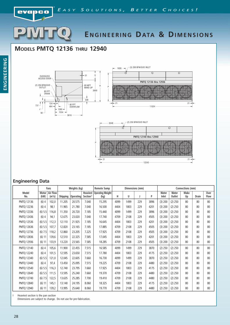
MODELS PMTQ 12136 THRU 12940
ENG INEER ING DATA & DIMENS IONS
Engineering Data
Fans Weights (kg) Remote Sump Dimensions (mm) Connections (mm)Model Motor Air Flow Heaviest Operating Weight Water Water Make OverNo. (kW) (m3/s) Shipping Operating Section† (kg) H U J P Inlet Outlet Up Drain Flow
PMTQ 12136 (6) 4 102,0 11.205 20.575 7.040 15.295 4099 1499 229 3896 (3) 200 (2) 250 80 80 80
PMTQ 12236 (6) 4 98,1 11.965 21.780 7.040 16.500 4404 1803 229 4201 (3) 200 (2) 250 80 80 80
PMTQ 12336 (6) 5.5 116,8 11.350 20.720 7.185 15.440 4099 1499 229 3896 (3) 200 (2) 250 80 80 80
PMTQ 12436 (6) 4 94,1 12.675 23.020 7.040 17.740 4709 2108 229 4505 (3) 200 (2) 250 80 80 80
PMTQ 12536 (6) 5.5 112,3 12.110 21.925 7.185 16.645 4404 1803 229 4201 (3) 200 (2) 250 80 80 80
PMTQ 12636 (6) 5.5 107,7 12.820 23.165 7.185 17.885 4709 2108 229 4505 (3) 200 (2) 250 80 80 80
PMTQ 12736 (6) 7.5 118,2 12.860 23.205 7.225 17.925 4709 2108 229 4505 (3) 200 (2) 250 80 80 80
PMTQ 12836 (6) 11 139,6 12.510 22.325 7.585 17.045 4404 1803 229 4201 (3) 200 (2) 250 80 80 80
PMTQ 12936 (6) 11 133,9 13.220 23.565 7.585 18.285 4709 2108 229 4505 (3) 200 (2) 250 80 80 80
PMTQ 12140 (6) 4 105,6 11.900 22.455 7.515 16.585 4099 1499 229 3870 (2) 250 (2) 250 80 80 80
PMTQ 12240 (6) 4 101,5 12.595 23.650 7.515 17.780 4404 1803 229 4175 (2) 250 (2) 250 80 80 80
PMTQ 12340 (6) 5.5 121,0 12.045 22.605 7.660 16.730 4099 1499 229 3870 (2) 250 (2) 250 80 80 80
PMTQ 12440 (6) 4 97,4 13.450 25.095 7.515 19.225 4709 2108 229 4480 (2) 250 (2) 250 80 80 80
PMTQ 12540 (6) 5.5 116,3 12.740 23.795 7.660 17.925 4404 1803 229 4175 (2) 250 (2) 250 80 80 80
PMTQ 12640 (6) 5.5 111,5 13.595 25.240 7.660 19.370 4709 2108 229 4480 (2) 250 (2) 250 80 80 80
PMTQ 12740 (6) 7.5 122,5 13.635 25.285 7.700 19.410 4709 2108 229 4480 (2) 250 (2) 250 80 80 80
PMTQ 12840 (6) 11 145,1 13.140 24.195 8.060 18.325 4404 1803 229 4175 (2) 250 (2) 250 80 80 80
PMTQ 12940 (6) 11 139,2 13.995 25.640 8.060 19.770 4709 2108 229 4480 (2) 250 (2) 250 80 80 80
† Heaviest section is the pan sectionDimensions are subject to change. Do not use for pre-fabrication.
P
(3) 200 BFW/GVD INLET1826
1102421 21
80 MPTMAKE-UP
124464
12801534
361692
J
737
OVERSIZEDACCESS DOOR
(2) 250 BFW/GVDOUTLET
80 FPTDRAIN
80 FPTOVERFLOW
2600
U
H
508
51
P
(2) 250 BFW/GVD INLET3048
1224321 21
PMTQ 12136 thru 12936
PMTQ 12140 thru 12940
ENGINEERING
E A S Y S O L U T I O N S , B E T T E R C H O I C E S !
29
ENGINEER ING DATA & DIMENS IONS
PipingCooling tower piping should be designed and installed inaccordance with generally accepted engineering practices.All piping should be anchored by properly designedhangars and supports with allowance made for possibleexpansion and contraction. No external loads should beplaced upon cooling tower connections, nor should any ofthe piping supports be anchored to the unit framework.
Capacity ControlThe design wetbulb for which the tower is sized occursonly a small percentage of the time. Unless colder watertemperatures are beneficial to the process being cooled,some form of capacity control will be needed. A commoncontrol practice is to cycle the fans off when leavingwater is below the minimum allowable temperature.However, this does not provide close control of theleaving water temperature and may cycle the motor onand off more than the recommended limit of six (6) startsper hour. Another method is to use a Variable FrequencyDrive (VFD) to control the fan speed. When a VFD isutilized, EVAPCO recommends the use of inverter dutymotors, which are available as standard.Another variable speed option is the use of a 2-speed fanmotor. This arrangement gives three (3) stages of capacitycontrol – 10% with the fans off, 60% (fans at 1/2 speed)and 100% (fans at full speed).Variable speed motors also save operating costs. At half-speed, the motor draws approximately 15% of full loadpower. Since maximum wet bulb and maximum loadseldomly coincide on air conditioning systems, the coolingtower will actually operate at a reduced speed most ofthe time. Contact the factory for a more detailed analysis.Caution: The water circulation pump must be interlockedwith the fan motor starter(s) to ensure water flow overthe tower fill during fan operation.
Maintaining the Recirculated Water SystemThe cooling in a tower is accomplished by the evaporationof a portion of the recirculated spray water. As this waterevaporates, it leaves behind its mineral content andimpurities. Therefore, it is important to bleed-off anamount of water equal to that which is evaporated toprevent the build up of impurities. If this is not done, themineral content and/or the corrosive nature of the waterwill continue to increase. This will ultimately result inheavy scaling or a corrosive condition.
Bleed-offA bleed line should be installed in the piping, external tothe unit. The bleed line must be properly sized for theapplication, and provided with a metering connection andglobe valve. The recommended bleed off for a coolingtower is equivalent to the evaporation ratio of 1,58 l/hper kW of cooling. If the make-up water supplying theunit is relatively free of impurities, it may be possible toreduce the amount of bleed, but the unit must beinspected frequently to make sure scale is not forming.Make-up water pressure must be maintained between 140and 340 kPa for proper operation of the standard floatvalve.
Water TreatmentIn some cases the make-up water will be so high inmineral content that a normal bleed-off will not preventscaling. In this case, water treatment will be required anda reputable water treatment company familiar with thelocal water conditions should be consulted. Any chemicalwater treatment used must be compatible with thematerials of construction of the unit. The pH of the watershould be maintained between 6.5 and 8.3. In order toprevent “white rust”, the galvanized steel in the unit mayrequire routine passivation of the steel when operating inhigher pH levels. Batch chemical feeding is notrecommended because it does not afford the properdegree of control. If acid cleaning is required extremecaution must be exercised and only inhibited acidscompatible with galvanized steel construction should beused.
Control of Biological ContaminationWater quality should be checked regularly for biologicalcontamination. If biological contamination is detected, amore aggressive water treatment and mechanical cleaningprogram should be undertaken. The water treatmentprogram should be performed by a qualified watertreatment company. It is important that all internalsurfaces be kept clean of accumulated dirt and sludge. Inaddition, the drift eliminators should be maintained ingood operating condition.
NOTE: The location of the cooling tower must beconsidered during the equipment layout stages of aproject. It is important to prevent the discharge of air(potential of biological contamination) from beingintroduced into the fresh air intakes of the building
ENGINEERING
E A S Y S O L U T I O N S , B E T T E R C H O I C E S !

30
S P E C I F I C A T I O N S
SP
EC
IFIC
AT
ION
SE A S Y S O L U T I O N S , B E T T E R C H O I C E S !
1.0 FORCED DRAFT LPT COOLING TOWER
1.1 GeneralFurnish and install factory assembled cooling tower of blowthrough, counterflow design with a horizontal single air sideentry and a vertical air discharge. The unit shall be completelyfactory assembled and be conform to the specifications andschedules.
The total fan power should not exceed _____ kW and thetotal overall unit dimensions should not exceed thefollowing:Length: mmWidth: mmHeight: mm
The unit will be delivered in two parts: the section (pan-fan)and the top section (heat transfer).The unit (top and bottom section) shall be joined togetherwith elastic sealer and bolted together with corrosionresistant fasteners.
Approved manufacturer: Evapco – model PMTQ ________
1.2 Thermal Performance – Performance Warranty The tower shall be capable of performing the thermal duties asshown in the schedule and on the drawings, and its designthermal rating shall be certified by the Cooling TechnologyInstitute (C.T.I.) and the Eurovent Certification Company (ECC).Only models with performance certified by CTI and ECC willbe approved.
Manufacturers’ performance guarantee without CTI-ECCcertification for the proposed model or an independent fieldperformance test shall not be accepted.
1.3 Applicable Standards a) ATC 128 Test Code for Measurement of Sound from
Water Cooling Towers b) CTI STD 201 Standard for Thermal Performance
Certification of Evaporative Heat Rejection Equipment c) Eurovent Rating Standard for Cooling Towers
1.4 Submittals a) The manufacturer shall submit a five year history of the
proposed type of cooling tower with a minimum of 10installations for similar sized equipment.
b) Shop drawings: submit shop drawings indicatingdimensions, weight loadings and required clearances.
c) Product data: submit manufacturer’s technical productdata, original selection printouts and clearancerequirements.
d) Performance data: submit curves showing certified andguaranteed cooling tower performance with variation inoutdoor air wet bulb temperature at design air flow anddesign flow rate. In addition submit performance curves for 90% and 110%of design water flow rate, indicating the cooling towertemperatures versus the ambient air wet bulbtemperatures.
e) Complete noise data sheet for the selected cooling tower.f) Maintenance data for the cooling tower and accessories.g) The cooling tower manufacturer shall provide factory test
run certificates of the fans and fan motor.
1.5 Product Delivery – Storage and Handlinga) The contractor shall make the provisions for proper
storage at site before installation and handle the productper the instructions of the manufacturer.
b) Once installed provide the necessary measures that theunits remain clean and protected from any dust andmechanical damage.
1.6 Quality Assurance a) The manufacturer shall have a quality assurance system in
place which is certified by an accredited registrar and
complying with the requirements of ISO 9001:2008.This is to guarantee a consistant level of product andservice quality.
b) Manufacturers without ISO 9001:2008 certification arenot acceptable.
1.7 Warranty a) The products will be warranted for a period of minimum
two years from the date of shipment.
2.0 PRODUCT
2.1 Construction – Corrosion Resistance
STANDARD EXECUTION – GALVANIZED STEEL Z-725
a) The structure and all steel elements of the pan and casingshall be constructed of Z-725 hot dip galvanized steel forlong life and durability. Alternatives with lower zinc layerthickness and external paint or coating are not acceptedas equal.
b) The strainer shall be made of stainless steel type 304L. c) During fabrication all panel edges shall be coated with a
95% pure zinc compound. d) Casing materials shall be of non flammable construction.
OPTIONAL EXECUTION – BASIN IN SST 304L
a) The structure and all steel elements of the Basin andLouver section up to the water level shall be made of SST304L.
b) Alternatives with hot dip galvanized steel and epoxycoatings in lieu of the SST 304L are not considered to beequal and are not accepted.
c) All other steel components of the casing shall beconstructed of Z-725 hot dip galvanized steel for long lifeand durability. Alternatives with lower zinc layer thicknessand external paint or coating are not accepted as equal.
d) The strainer shall be made of stainless steel type 304L. e) During fabrication all galvanized steel panel edges shall
be coated with a 95% pure zinc compound. f) Casing materials shall be of non flammable construction.
UAT EXECUTION – Complete Unit SST 304L (except moving parts)
a) The structure and all steel elements shall be made of SST304L.
b) Alternatives with hot dip galvanized steel and epoxycoatings in lieu of the SST 304L are not considered equal andaccepted.
c) Casing materials shall be of non flammable construction.
2.2 Construction – Seismic and wind load resistance a) The structural design must withstand 1g seismic or
2.87 kN/m² wind loads.b) Cooling Towers must be independently certified
according to IBC 2009.
2.3 Pan / Fan section a) The heat transfer section shall be removable from the
pan to provide easy handling and rigging.b) The pan – fan section shall include fans and drives
mounted and aligned in the factory. These items shall belocated in the dry air stream.
c) Standard pan accessories shall included circular accessdoors, strainer(s) of anti vortex design, brass make upvalve with unsinkable, foam filled plastic float arrangedfor easy adjustment.
d) The basin bottom shall be sloped to provide drainage ofthe complete basin section.
2.4 Mechanical Equipment
2.4.1 Fan(s)a) Fans shall be extremely wide chord axial, one piece heavy
duty propeller type, statically balanced and made of FRP.

31
S P E C I F I C A T I O N S
SP
EC
IFIC
AT
ION
S
E A S Y S O L U T I O N S , B E T T E R C H O I C E S !
b) Fans shall be installed in a closely fittied cowl withventure air inlet for maximum fan efficiency.
c) Curved inlet rings shall be made of the same material asthe cooling tower.
d) All fans will undergo a dry running test in the factoryafter being installed in the cooling tower basin.
e) Fan Housing: the complete drive system, including theelectric motor, belts, bearings, fan, and drives shall becompletely enclosed in a protective housing which coversthe drive system and provides sound reduction.
f) Easy to remove fan screens shall be provided to avoiddirect contact with the moving parts.
2.4.2 Bearings and Drive a) The fan shaft(s) shall be supported by heavy duty, self
aligning pillow block bearings with cast iron housingsand lubrication fittings for maintenance.
b) The fan drives shall be V belt type with taper locksheaves designed for 150% of the motor nameplatehorsepower.
c) The bearings shall be rated for an L-10 life of 75.000 to135.000 hours.
2.4.3 Motor a) The fan motor shall be Totally Enclosed, Fan Cooled
(TEFC) , squirrel cage, ball bearing type motor. b) The motor shall be minimum IP 55 degree of protection,
Class F insulation, Service Factor 1 and selected for theappropriate cooling tower duty and the correct ambienttemperature but minimum 40°C.
c) Motor bearings shall be greased for life or externalgrease lines shall be provided.
d) The motor shall be mounted on an adjustable heavy dutysteel motor base.
e) The motor selection shall be selected for the appropriateexternal static pressure.
f) The motor power supply shall be _____ volts, ___ Hertzand ______ Phase.
2.5. Casing Section
2.5.1 Heat Transfer a) The cooling tower fill shall be PVC (Polyvinyl Chloride) of
cross fluted design for optimum heat transfer and efficiency.b) The cross fluted sheets shall be bonded together for
maximum strength and durability. Fill packs which arenot bonded are not allowed.
c) The PVC fill shall be self extinguishing for fire resistancewith a flame spread rating of 5 per ASTM–E-84–81a.
d) The fill shall be resistant to rot, decay or biological attack.e) The fill shall be able to withstand a water temperature of
55°C. The fill sheets will be bonded together in such away that the structural integrity of the fill makes the filluseable as a working platform.
f) The cooling tower manufacturer shall be responsible forthe manufacturing and performance testing of the fill.This is to assure single source responsibility.
2.5.2 Water Distribution a) The spray header and branches shall be constructed of
Schedule 40, Polyvinyl Chloride (PVC) pipe for corrosionresistance and shall have a steel connection to attach theexternal piping.
b) The internal tower water distribution piping shall beeasily removable for cleaning purposes.
c) The branches have threaded end caps to assist with debrisremoval.
d) The water shall be distributed over the fill by precisionmolded ABS spray nozzles with large minimum 25 mmorifice openings and integral sludge ring to eliminateclogging.
e) The nozzles shall be threaded into the water distributionpiping to assure positive positioning. The nozzles arelocated on the side of the header to allow the largerdebris to flow easily through the water distributionsystem.
f) Each cell shall have only one hot water return inlet,otherwise the cooling tower manufacturer shall providethe necessary extra provisions (piping, balancing valves, …)to achieve the same at no extra cost.
2.5.3 Drift Eliminators a) The drift eliminators shall be constructed entirely inert
polyvinyl (PVC) that has been specially treated to resistultra violet light.
b) Assembled in easily handled sections, the eliminatorblades shall be spaced on 25 mm centers and shallincorporate three changes in air direction to assureefficient removal of entrained moisture from thedischarge air stream.
c) The maximum drift rate shall not exceed 0,001% of therecirculated water rate.
d) The Drift Eliminators shall be certified according toEurovent Standard OM-14-2009.
2.6 Sound LevelsThe maximum sound pressure levels (dB) measured 15m from the cooling tower operating at full fan speed shall not exceed the sound levels detailed below.
Location 63Hz 125Hz 250Hz 500Hz 1000Hz 2000Hz 4000Hz 8000Hz dB(A)DischargeAir inlet
3.0 ACCESSORIES (optional)
3.1 Electric Heaters a) The cooling tower cold water basin shall be provided
with a electric heater package to prevent freezing of thewater in the cold water basin.
b) The electric heater package includes: electric heaterelements and a combination of thermostat and lowwater level cutoff.
c) The heaters shall be selected to maintain 4°C basin watertemperature at _____°C ambient
d) The heater(s) shall be ____V / ____ phase / ____ Hz electricpower supply.
3.2 Three Probe Electric Water Level Control Packagea) The cooling tower manufacturer shall provide an electric
water level control package instead of the mechanicalfloat valve arrangement.
b) The package consist of the following elements:- Multiple heavy duty stainless steel SST 316 static probes
mounted in a stilling tube outside the unit. Electrodesor sensors mounted inside the unit are not accepted asthere operation will disturbed by the moving water inthe basin.
- A ABS, IP 56 case contains all the contactors for thedifferent level probes and will provide a output signal ofa relay for automatic filling and one relay for alarm level.
- The power supply to the control package is24 Vac / 230 Vac - ____ Hz .
- A weather protected solenoid valve for the watermake up ready for Piping to a water supply withpressure between 140 kPa and 340 kPa.
3.3 Vibration Switch a) A vibration limit switch shall be installed on the
mechanical equipment support and wired into thecontrol panel. The purpose of this switch will be tointerrupt power the motor in the event of excessivevibration.
b) The switch shall be adjustable for sensitivity, and shallrequire manual reset.

EVAPCO, Inc.— World Headquarters & Research/Development Center
EVAPCO, Inc.World HeadquartersP.O. Box 1300Westminster, MD 21158 USAPhone: 410-756-2600Fax: 410-756-6450E-mail: [email protected]
EVAPCO East5151 Allendale LaneTaneytown, MD 21787 USAPhone: 410-756-2600Fax: 410-756-6450E-mail: [email protected]
EVAPCO Midwest1723 York RoadGreenup, IL 62428 USAPhone: 217-923-3431Fax: 217-923-3300E-mail: [email protected]
EVAPCO West1900 West Almond AvenueMadera, CA 93637 USAPhone: 559-673-2207Fax: 559-673-2378E-mail: [email protected]
EVAPCO Iowa925 Quality DriveLake View, IA 51450 USAPhone: 712-657-3223Fax: 712-657-3226
EVAPCO IowaSales & Engineering215 1st Street, NEP.O. Box 88Medford, MN 55049 USAPhone: 507-446-8005Fax: 507-446-8239E-mail: [email protected]
EVAPCO Newton701 East Jourdan StreetNewton, IL 62448 USAPhone: 618-783-3433Fax: 618-783-3499E-mail: [email protected]
EVAPCO-BLCT Dry Cooling, Inc.981 US Highway 22 WestBridgewater, NJ 08807 USAPhone: 1-908-379-2665E-mail: [email protected]
Refrigeration Valves &Systems CorporationA wholly owned subsidiary of EVAPCO, Inc.1520 Crosswind Dr.Bryan, TX 77808 USAPhone: 979-778-0095Fax: 979-778-0030E-mail: [email protected]
McCormack Coil Company, Inc.A wholly owned subsidiary of EVAPCO, Inc.P.O. Box 17276333 S.W. Lakeview BoulevardLake Oswego, OR 97035 USAPhone: 503-639-2137Fax: 503-639-1800E-mail: [email protected]
EvapTech, Inc.A wholly owned subsidiary of EVAPCO, Inc.8331 Nieman RoadLenexa, KS 66214 USAPhone: 913-322-5165Fax: 913-322-5166E-mail: [email protected]
Tower Components, Inc.A wholly owned subsidiary of EVAPCO, Inc.5960 US HWY 64ERamseur, NC 27316Phone: 336-824-2102Fax: 336-824-2190E-mail: [email protected]
EVAPCO Europe, N.V.European HeadquartersIndustrieterrein Oost 40103700 Tongeren, BelgiumPhone: (32) 12-395029Fax: (32) 12-238527E-mail: [email protected]
EVAPCO Europe, S.r.l.Via Ciro Menotti 10I-20017 Passirana di Rho, Milan, ItalyPhone: (39) 02-939-9041Fax: (39) 02-935-00840E-mail: [email protected]
EVAPCO Europe, S.r.l.Via Dosso 223020 Piateda Sondrio, Italy
Flex Coil a/sA subsidiary of Evapco, Inc.Knøsgårdvej 115 9440 Aabybro, DenmarkPhone: (45) 9824-4999 Fax: (45) 9824-4990 E-mail: [email protected]
EVAPCO Europe, GmbHBovert 22, Meerbuscher Str. 64-78, Haus 5D-40670 Meerbusch, GermanyPhone: (49) 2159-69560Fax: (49) 2159-695611E-mail: [email protected]
EVAPCO S.A. (Pty.) Ltd.A licensed manufacturer of Evapco, Inc.18 Quality RoadIsando 1600, Republic of South AfricaPhone: (27) 11 392-6630Fax: (27) 11-392-6615E-mail: [email protected]
Evap Egypt Engineering Industries Co.5 Al Nasr Road St.Nasr City, Cairo, EgyptPhone: (20) 2-24022866 / (20) 2-24044997/8Fax: (20) 2-404-4667/ Mob: (20) 12-3917979E-mail: [email protected]
EVAPCO ChinaAsia/Pacific Headquarters1159 Luoning Rd. Baoshan Industrial ZoneShanghai, P. R. China, Postal Code: 200949Phone: (86) 21-6687-7786Fax: (86) 21-6687-7008E-mail: [email protected] (Shanghai) RefrigerationEquipment Co., Ltd.1159 Louning Rd., Baoshan Industrial ZoneShanghai, P.R. China, Postal Code: 200949Phone: (86) 21-6687-7786Fax: (86) 21-6687-7008E-mail: [email protected] EVAPCO RefrigerationEquipment Co., Ltd.Yan Qi Industrial Development DistrictHuai Rou CountyBeijing, P.R. China, Postal Code: 101407Phone: (86) 10 6166-7238Fax: (86) 10 6166-7395E-mail: [email protected]
EVAPCO Australia Pty Ltd.34-42 Melbourne Road - P.O. Box 436Riverstone, N.S.W. Australia 2765Phone: (61) 29 627-3322Fax: (61) 29 627-1715E-mail: [email protected]
EvapTech Composites Sdn. BhdNo. 70 (Lot 1289) Jalan Industri 2/3Rawang Integrated Industrial ParkRawang, Selangor, 48000 MalaysiaPhone: 60 3 6092-2209Fax: 60 3 6092-2210EvapTech Asia Pacific Sdn. BhdA wholly owned subsidiary of EvapTech, Inc.IOI Business Park, 2/F Unit 20Persiaran Puchong Jaya SelatanBandar Puchong Jaya,47170 Puchong, Selangor, MalaysiaPhone: +(60-3) 8070 7255Fax: +(60-3) 8070 5731E-mail: [email protected]
EVAPCO North America
EVAPCO, Inc. • P.O. Box 1300 • Westminster, MD 21158 USAPhone: +1 410-756-2600 • Fax: +1 410-756-6450 • E-mail: [email protected]
EVAPCO Europe EVAPCO Asia/Pacífic
Evapco Products are Manufactured Worldwide
EVAPCO... Specialists in Heat Transfer Products and Services.Visit EVAPCO’s Website at: http://www.evapco.eu
©2012 EVAPCO, Inc.
Bulletin 310-E Metric 1012
World Headquarters/Research and Development Center
EVAPCO ManufacturingLocations