e l e c t r i c d u c t h e a t e r s - Home :: Indeeco 800-243-8162 Choosing Open Coil or Finned...
64
ELECTRIC DUCT HEATERS open coil finned tubular explosion-proof & corrosion resistant electric heating and controls
Transcript of e l e c t r i c d u c t h e a t e r s - Home :: Indeeco 800-243-8162 Choosing Open Coil or Finned...
e l e c t r i c
d u c t h e a t e r s
open coil finned tubular explosion-proof &corrosion resistant
electric heating and controls
I n t r o d u c t i o n
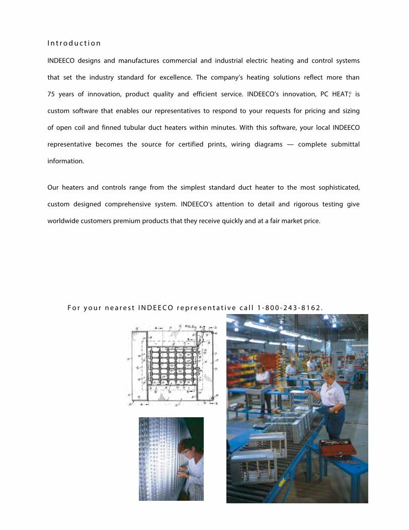
INDEECO designs and manufactures commercial and industrial electric heating and control systems
that set the industry standard for excellence. The company’s heating solutions reflect more than
75 years of innovation, product quality and efficient service. INDEECO’s innovation, PC HEAT ,© is
custom software that enables our representatives to respond to your requests for pricing and sizing
of open coil and finned tubular duct heaters within minutes. With this software, your local INDEECO
representative becomes the source for certified prints, wiring diagrams — complete submittal
information.
Our heaters and controls range from the simplest standard duct heater to the most sophisticated,
custom designed comprehensive system. INDEECO’s attention to detail and rigorous testing give
worldwide customers premium products that they receive quickly and at a fair market price.
F o r y o u r n e a r e s t I N D E E C O r e p r e s e n t a t i v e c a l l 1 - 8 0 0 - 2 4 3 - 8 1 6 2 .

Contents
www.indeeco.com 800-243-8162
Choosing Open Coil or Finned Tubular Design
Specific Requirements3 Calculating KW Requirements3 Static Pressure Drop4 Minimum Velocity4 Maximum Velocity5 Airflow Uniformity6 Multiple Heaters in the Duct6 Clearance7 UL and NEC Requirements7 International Requirements
Installation Information8 Heater Installation8 Field Wiring
Standard Control Options10 Internal Wiring10 Control Option G — Basic10 Control Option J — Pneumatic11 Control Option K — Proportional12 Thermostats
Construction – Electrical14 Bi-Metallic Thermal Cutouts14 Linear Thermal Cutouts15 Airflow Switch15 Fan Relay16 Magnetic Contactors16 Fuses16 Control Transformer17 Disconnect Switch17 Pilot Lights17 Pilot Switch17 Pneumatic/Electric (PE) Switches18 Electronic Controls18 SCR Power Controllers19 Step Controllers (Sequencers)20 Step Controllers (Microprocessor-based)21 Vernier Proportional Control21 Thermostats/Inputs for Electronic Controls
Construction – Mechanical22 Slip-in Heaters22 Flanged Heaters22 Zero Clearance Construction23 Physical Standards
Standard Duct Heaters – Open Coil24 QUA Slip-in and QUZ Flanged Heaters24 KW Ratings24 Frame Sizes25 Sizes and Maximum KW Ratings26 Detail Dimensions26 Voltage and Phase26 Control Circuit Options & Special Features26 Number of Heating Stages27 Special Features31 QUA/QUZ – Sample Specification
Custom Duct Heaters32 Special Applications33 Round Duct Construction 34 Duct Heaters for Wet, Dusty and Corrosive Areas35 Bottom Mounted Terminal Box35 Insulated Terminal Box35 Pressure Plates36 Protective Screens36 Unheated Sections36 Construction for Lined Ducts37 Slip-and-Drive Construction37 Remote Panelboard37 Minimum & Maximum Duct Dimensions39 Open Coil Custom Heater – Sample Specification40 Finned Tubular Custom Heater – Sample Specification
Explosion-proof Duct Heaters41 Safety41 Experience41 Complete Product Line41 Applications41 Use of Electric Heaters in Hazardous Areas42 National Electrical Code Classification42 Class42 Division43 Group44 Engineering Information 44 Airflow Requirements45 Comparison Chart
ULTRA-SAFE™ Explosion-proof Duct Heaters46 Standard Construction46 Installation47 Temperature Control48 Standard Heater Listing49 Custom Options50 How to Order50 Sample Specification
Series EP2 Explosion-proof Duct Heaters51 Standard Construction51 Control Options51 Installation52 Custom Options53 How to Order53 Sample Specification
Custom Explosion-proof Duct Heaters54 Construction55 How to Order55 Sample Specification56 Typical Wiring Diagrams
Limited Warranty
INDEECO Products
1
Choosing Open Coil or Finned Tubular Design
www.indeeco.com 800-243-8162
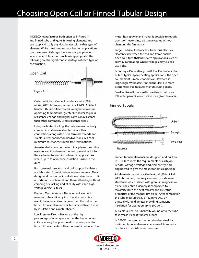
INDEECO manufactures both open coil (Figure 1) and finned tubular (Figure 2) heating elements and can supply virtually any duct heater with either type of element. While most simple space heating applications use the open coil design, there are many applications where finned tubular construction is appropriate. The following are the significant advantages of each type of construction.
Open Coil
Only the highest Grade A resistance wire (80% nickel, 20% chromium) is used in all INDEECO duct heaters. This iron-free wire has a higher maximum operating temperature, greater life, lower sag, less resistance change and higher corrosion resistance than other commonly used resistance wires.
Using calibrated tooling, the coils are mechanically crimped into stainless steel terminals. This connection, along with 10-32 terminal threads and stainless steel connection hardware, insures cool, minimum resistance, trouble free terminations.
An extended shank on the terminal places the critical resistance coil-to-terminal connection well out into the airstream to keep it cool even in applications where up to 1” of interior insulation is used in the duct.
Both terminal insulators and coil support insulators are fabricated from high-temperature ceramic. Their design and method of installation enable them to: 1) absorb both mechanical and thermal loading without chipping or cracking and 2) easily withstand high voltage dielectric tests.
Element Temperature – The open coil element releases its heat directly into the airstream. As a result, the open coil runs cooler than the coil in the finned tubular element which is isolated from the air by insulation and a metal sheath.
Low Pressure Drop – Because of the high percentage of open space across the heater, open coils have very low pressure drop as compared to finned tubular heaters. This can result in reduced fan
2
motor horsepower and makes it possible to retrofit open coil heaters into existing systems without changing the fan motor.
Large Electrical Clearances – Generous electrical clearances between the coil and frame enable open coils to withstand severe applications such as subway car heating, where voltages may exceed 750 volts.
Economy – On relatively small, low KW heaters (the bulk of typical space heating applications) the open coil element is more economical. However, in large, high KW heaters, finned tubulars are more economical due to lower manufacturing costs.
Smaller Size – It is normally possible to get more KW with open coil construction for a given face area.
Finned Tubular
Finned tubular elements are designed and built by INDEECO to meet the requirements of each job. Length, wattage, voltage and element style are engineered to give the most economical package.
All elements consist of a Grade A coil (80% nickel, 20% chromium), precisely centered in a stainless steel tube which is filled with granular magnesium oxide. The entire assembly is compacted to maximize both the heat transfer and dielectric properties of the magnesium oxide. After compaction the tube measures 0.475” (12 mm) O.D., an unusually large diameter providing sufficient insulation for operation up to 600 volts.
A stainless steel fin is helically wound onto the tube to increase its heat transfer surface.
INDEECO has standardized on stainless steel for its finned tubular elements because of its superior resistance to moisture and corrosion.
Figure 1.
Figure 2.
U-Bent
Straight
Two-Pass

Specific Requirements
www.indeeco.com 800-243-8162
3
Straight, Two-Pass and U-Bent elements are furnished with mounting flanges, making them individually removable through the terminal box.
Safety – Because the heating coil is completely encased in a grounded metal sheath, shock hazard due to accidental contact with the coil is eliminated. Heaters installed close to a register, grille, or access door should either use finned tubular construction or an open coil unit with a protective screen.
Airflow Contamination – If airborne contamination, such as dirt or dust, builds up on open coil elements during shutdown periods, the elements can short out. Finned tubular elements, with their insulated coils, eliminate this problem. Furthermore, upon start-up, a finned tubular heater which has been exposed to droplets of water in the airstream (e.g. immediately downstream from a spray type humidifier, a cooling coil, or a fresh air intake) cannot short to ground as open coils can when support bushings are wet.
Serviceability – In the unlikely event of element failure, it is easier to replace individually mounted finned tubular elements than open coil elements.
Mechanical Stability – Finned tubular elements are more rugged than open coils. They will withstand more physical abuse.
Airflow Uniformity – Finned tubular duct heaters tend to be more tolerant of nonuniform airflow conditions. Heat conducted along the element length reduces or eliminates hot spots resulting from nonuniform airflow. With open coil heaters, it may be necessary to use a pressure plate to compensate for bad airflow conditions.
Controllability – Because of their relatively high thermal inertia, finned tubular elements controlled with on/off thermostat systems provide more precise control. Furthermore, finned tubular elements cycle at a reduced rate, thus increasing the life of the power components such as contactors. Nevertheless, when SCR controllers are used, equally precise control can be obtained with either construction.
Calculating KW RequirementsOnce the volume of airflow (CFM – in cubic feet per minute) and the required temperature rise (∆T – in degrees F) through the heater are known, the required kilowatt rating (KW) of the heater can be determined from the formula:
KW = CFM x ∆T°F KW = Liters/Second x ∆T°C 3193 837
Where the desired heating capacity in BTU/Hr is known, the KW is determined from the following formula:
KW = BTU/Hr 3412
Static Pressure DropStatic pressure drop through an open coil heater is quite low and, in most cases, can be ignored when calculating system pressure drop. The pressure drop across a finned tubular heater is greater than across an open coil. However, if pressure plates must be added to an open coil, the pressure drop over the open coil far exceeds the drop over a finned tubular heater. The curves in Figure 3 give data for all three constructions.
Figure 3.
( (

Specific Requirements
www.indeeco.com 800-243-8162
Minimum VelocityElectric heaters differ from steam or hot water coils in that the heat output is constant as long as the heater is energized. Therefore, sufficient airflow must be provided to prevent overheating and nuisance tripping of the thermal cutouts. The minimum required velocity is determined from Figure 4A or 4B on the basis of entering air temperature and KW per square foot of cross sectional duct area.
The maximum air inlet temperature for open coil heaters is 100°F (38°C) and for finned tubular heaters is 80°F (27°C).
Example: Determine whether the minimum air velocity requirement is met for a 10 KW open coil heater installed in a 24” wide x 12” high duct operating with 1000 cubic feet per minute (CFM) of air at a maximum inlet temperature of 65°F:
4
1. Duct Area = 24” x 12”/144 = 2 sq. ft.2. KW per square foot = 10 KW/2 sq. ft. = 5.3. Go to Figure 4B. Use top curve (below 80°F inlet
air).Find 5 KW per square foot on the vertical axis. Read minimum velocity required, which in this case is 310 feet per minute (FPM).
4. Heater air velocity = 1000 CFM/2 sq. ft. = 500 FPM. Since 500 FPM exceeds the minimum, this
installation is safe. Consult your local INDEECO representative for assistance if you do not have sufficient air velocity.
High velocity airflow is not normally encountered in typical commercial HVAC applications, when installing open coil duct heaters into velocities over 1200 feet per minute contact your local INDEECO representative.
Figure 4A. Figure 4B.
Maximum Velocity
100
2
200 300 400 500 600 700 800 900 1000 1100 1200
4
6
8
10
12
14
16
00
KW P
ER S
QU
ARE
FO
OT
DU
CT
ARE
A
MINIMUM AIR VELOCITY REQUIRED(FEET PER MINUTE)
FINNEDTUBULAR
CONSTRUCTION
MINIMUM AIR VELOCITY REQUIRED(FEET PER MINUTE)
KW P
ER S
QU
ARE
FO
OT
DU
CT
ARE
A
OPEN COILCONSTRUCTION
100
2
200 300 400 500 600 700 800 900 1000 1100 1200
4
6
8
10
12
14
16
18
22
24
26
28
30
32
20
91��100��������
���
81��90����������
�
������80�����������
00

Specific Requirements
www.indeeco.com 800-243-8162
5
Airflow UniformityTo prevent hot spots, airflow must be uniformly distributed across the heater face. Figure 5 illustrates typical heater misapplications which result in non-uniform airflow. The heater’s UL Listing requires that it not be installed closer than 4’ (122 cm) downstream or upstream from a fan outlet, abrupt transition, or other obstructions. Elbows or turns must be located at least 4’ (122 cm) from inlet of the heater and 2’ (61 cm) from outlet of the heater.
If such an installation cannot be avoided, consult your local INDEECO representative for assistance. We can provide a pressure plate, non-heated zones or special low watt density coils to overcome these problems. Final approval of such applications is up to the local inspection authority.
Heater too close to fan
Heater too close to elbow Heater partially blocked by filter or frame member
Heater adjacent to transition
Figure 5.

Specific Requirements
www.indeeco.com 800-243-8162
Multiple Heaters in the DuctINDEECO heaters are designed to be used singly, not in series in a duct. Since INDEECO heaters can be furnished in virtually any size and KW rating, series installation of heaters can be avoided.
For very large heaters, field installation and shipping may be simplified by using two or more sections designed for parallel installation, illustrated by Figure 6. Each section, furnished in the flanged design, has individual thermal cutouts. Terminal blocks are provided to interconnect these cutouts in the field. Sections rest stably one on top of the other.
Heaters more than 6’ (152 cm) high are normally provided in sections, but larger single section heaters can be provided. Consult your local INDEECO representative for details.
6
ClearanceINDEECO heaters are UL Listed for zero clearance to combustible surfaces. Thus, there is no minimum distance between combustible materials and the section of duct housing the heater, or the heater itself. However, the terminal box must be accessible for servicing. The NEC requires a minimum workspace at least 30” (76 cm) wide by 42” (107 cm) deep for access to the heater terminal box. More space is required for large heaters and for removal of slip-in heaters which are over 42” long.
In addition, sufficient clearance must be provided for convection cooling of all heaters with built-in SCR power controllers (Figure 7). Allow at least 5” (12.7 cm) of free air space around the cooling fins extending from the heater terminal box. Enclosing the fins in any fashion, insulating them, or preventing them from being cooled by normal convection will cause controller failure and void the heater warranty.
Figure 6. Figure 7.

Specific Requirements
www.indeeco.com 800-243-8162
7
UL and NEC RequirementsAll INDEECO electric duct heaters described in this catalog meet the requirements of Underwriters Laboratories (UL) and the National Electrical Code (NEC) unless otherwise indicated.†
Heaters furnished with one of the Control Options on pages 10 and 11 are automatically UL Listed and meet NEC requirements. Custom designed heaters must meet certain requirements to comply with UL and the NEC. The areas of particular concern are outlined below.
Overtemperature Protection – Duct heaters must be supplied with both primary and secondary overtemperature protection. All INDEECO heaters are provided with both automatic and manual reset thermal cutouts to serve this function.
Airflow Interlocks – An airflow interlock must be provided to keep the heater from operating with extremely low or no airflow. INDEECO’s standard, a built-in differential pressure airflow switch described on page 15, senses static pressure in the duct as an indicator of airflow. Separate wiring to the fan motor or its controls is unnecessary.
Alternative methods for detecting airflow include:
1. The fan relay, described on page 15, provides a positive electrical interlock with the fan circuit.
2. A separate contactor, built into the duct heater, can energize the fan when the duct heater is on.
3. A terminal block to allow field connection of external contacts that close the circuit only when the fan is operating.
Contactors – Contactors connected to the primary thermal cutout and airflow interlock safety circuits must be provided by the duct heater manufacturer. Effective June 2009 UL requires that all open coil element duct heaters be furnished with disconnecting
type controlling, safety and backup contactors breaking all ungrounded conductors. Practically speaking, this means that all, but small 120 and 277 volt single-phase open coil heaters, must be supplied with either disconnecting contactors built into the heater terminal box or into a remote panelboard. INDEECO’s standard is to supply disconnecting contactors which break all ungrounded conductors in open coil heaters. Due to the intrinsic safety of finned tubular duct heaters, UL does not require the use of disconnecting type contactors. INDEECO’s standard is to supply de-energizing contactors, which break only one line of single-phase circuits and two lines of three-phase circuits. Disconnecting contactors are available with finned tubular heaters if required.
Overcurrent Protection – For heaters drawing more than 48 amps, the duct heater manufacturer must provide some means of overcurrent protection either built into the terminal box or a remote panelboard. While fuses or circuit breakers are available to meet this requirement, INDEECO’s standard is fuses.
Disconnecting Means – All duct heater installations require a disconnecting means at or within sight of the heater controls. We recommend that a built-in, snap-acting, door interlocking disconnect switch with marked “on” and “off” positions be specified on all duct heaters. This insures the ultimate in safety, since the heater and built-in controls cannot be serviced without turning the disconnect switch off. It is also far less expensive than one obtained and installed in the field.
International RequirementsINDEECO heaters can be supplied to operate from any electrical system throughout the world. Single and three-phase voltages through 600 volts are available. As described on pages 24 through 31, all type QUA and QUZ standard heaters are available in 380, 400 or 415 volt, three-phase ratings. All INDEECO heaters will operate on either 50 or 60 Hz.
† Although UL requirements are uniform throughout the country, local electrical codes may deviate from the NEC. For information on local requirements, consult your INDEECO representative.

Installation Information
www.indeeco.com 800-243-8162
Heater InstallationSlip-in heaters slide through a rectangular opening in the side of the duct per Figure 8. The heater is designed for 1/4” (6.35 mm) clearance around the inside of the duct. Slip-in construction is normally preferred for ducts up to 4’ (122 cm) wide, but can be furnished for any width. The heaters are held in place with sheet metal screws through the back of the terminal box into the duct. However, if the duct is over 3’ (91 cm) wide, supporting rails in the bottom of the duct are recommended.
Flanged heaters are attached to matching external duct flanges per Figure 9. The heaters are secured by using either sheet metal screws or bolts and nuts through the flanges.
A special flanged construction installed with conventional HVAC slip-and-drive connectors is also available. See page 37 for details.
Either flanged or slip-in heaters can be installed in fiberglass ducts as illustrated in Figure 10. Note that a sheet metal liner must be installed into the fiberglass duct work, extending at least 6” (152 mm) beyond the heater terminal box on both sides, more if required for structural rigidity.
Field WiringBuilt-in power terminal blocks are sized for incoming copper conductors with 75°C insulation, rated to carry 125% of the heater load. However, lines may be sized to carry 100% of the heater load if a) the heater is rated at 50 KW or more, and b) the heater is controlled by a cycling device, such as a multi-staged thermostat, step controller, or SCR power controller. Terminal blocks and knockouts on such heaters will accommodate either 100% or 125% conductors. See Table I for field conductor and conduit sizing up to 500 MCM wiring. For higher amperages, terminal blocks are furnished for two or more parallel conductors per phase.
In general, aluminum conductors are not recommended and terminal blocks are not sized for aluminum. Consult your INDEECO representative if aluminum wire is specified for a particular job.
8
Figure 8.
Figure 9.
Figure 10.
Fiberglass Duct
Sheet Metal Liner
Sheet Metal Liner
Fiberglass Duct

Installation Information
www.indeeco.com 800-243-8162
9
Field control wiring should also be copper conductors with 75°C insulation. Thermostat circuits for SCR’s and step controllers are NEC Class II. Many small heaters with 24 volt control circuits are also NEC Class II. When Class II wiring is permissible, it will be shown on the wiring schematic. Other control circuits are NEC Class I.
When control power is taken from the heater’s load circuit lines, INDEECO provides for the overcurrent protection of all control circuits, as required by NEC or UL. When control circuit power is obtained from a separate source outside the heater, it is necessary for the installer to provide overcurrent protection for all control conductors.
Table I
Field Wiring and Conduit Sizing* for Incoming Conductors
Wire/
Trade KW in Voltages Shown Size Conduit Size Load Single-Phase Three-Phase AWG or (Inches) Amps 120V 208V 240V 277V 208V 240V 480V MCM 1Ø 3Ø 1.4 2.4 2.8 3.3 4.3 4.9 9.9 14 1/2 1/2 12 1.9 3.3 3.8 4.4 5.7 6.6 13.3 12 1/2 1/2 16 2.8 4.9 5.7 6.6 8.6 9.9 19.9 10 1/2 3/4 24 4.8 10.8 9.6 11.0 14.4 16.6 33.2 8 3/4 1 40 6.2 10.8 12.4 14.4 18.7 21.6 43.2 6 1 1 52 8.1 14.1 16.3 18.8 24.4 28.2 56.5 4 1 11/4 68 9.6 16.6 19.2 22.1 28.8 33.2 66.5 3 1 11/4 80 11.0 19.1 22.0 25.4 33.1 38.2 76.4 2 11/4 11/4 92 12.4 21.6 24.9 28.8 37.4 43.2 86.4 1 11/4 11/2 104 14.4 24.9 28.8 33.2 43.2 49.8 99.7 1/0 11/4 11/2 120 16.8 29.1 33.6 38.7 50.4 58.1 116.3 2/0 11/2 2 140 19.2 33.2 38.4 44.3 57.6 66.5 133.0 3/0 11/2 2 160 22.0 38.2 44.1 50.9 66.2 76.4 152.9 4/0 2 2 184 24.4 42.4 48.9 56.5 73.4 84.8 169.6 250 2 21/2 204 27.4 47.4 54.7 63.2 82.1 94.7 189.5 300 2 21/2 228 29.8 51.6 59.5 68.7 89.3 103.0 206.1 350 21/2 3 248 32.2 55.7 64.3 74.2 96.5 111.4 222.8 400 21/2 3 268 36.5 63.2 73.0 84.2 109.5 126.3 252.7 500 21/2 3 304
54.0 6 1 1 65 70.7 4 1 1 85 83.1 3 1 11/4 100 95.6 2 11/4 11/4 115 54.0 108.1 1 11/4 11/2 130 54.0 62.4 124.7 1/0 11/4 11/2 150 63.0 72.7 145.5 2/0 11/2 2 175 55.4 72.1 83.1 166.3 3/0 11/2 2 200 55.2 63.7 82.9 95.6 191.2 4/0 2 2 230 53.0 61.2 70.6 91.9 106.0 212.0 250 2 21/2 255 59.2 68.4 78.9 102.6 118.4 236.9 300 2 21/2 285 64.5 74.4 85.9 111.7 128.9 257.7 350 21/2 3 310 69.7 80.4 92.8 120.7 139.2 278.5 400 21/2 3 335 79.0 91.2 105.3 136.9 158.0 315.9 500 21/2 3 380
Sized For
125% of
Heater Load
Sized For
100% of
Heater Load
*These tabulations are based on Table 310-16 of the NEC. Not more than 3 conductors in a raceway; 75°C rated copper wire.

Standard Control Options
www.indeeco.com 800-243-8162
Internal WiringCopper wire with a minimum of 105°C insulation is used throughout. Connections are made with either box lugs or connectors crimped on with calibrated tooling. Terminal blocks are provided for all field control and power wiring.
INDEECO developed the Control Option concept to maintain compliance with changing UL and NEC requirements and to stay current with new duct heater temperature control systems. The concept has also been broadened to include numerous “Special Features” to meet a wide variety of special requirements.
Control Option G – BasicControl Option G is a basic package designed for normal comfort heating applications – i.e., those that do not require pneumatic control or the unique features of SCR control. With Option G, the temperature is controlled by a pilot duty thermostat or a step controller.
Control Option G includes the following:
• Automatic and manual reset thermal cutouts to protect against overheating. The automatic reset cutout is wired into the control circuit; the manual reset de-energizes the heater load.
• A differential pressure airflow switch to de-energize the heater control circuit upon loss of airflow.
• Magnetic contactors for each heater stage.
• Fuses to protect each circuit in any heater drawing more than 48 amps.
• A control circuit transformer, with 24 or 120 volt secondary as specified, including any overcurrent protection required by UL or the NEC.
• A built-in, snap-acting disconnect switch with door interlock to protect service personnel.
10
Control Option J – PneumaticControl Option J is designed for pneumatic temperature control.† The contractor need only connect one air line and the main power lines to the heater.
Option J includes the following:
• Automatic and manual reset thermal cutouts and a differential pressure airflow switch. The manual reset thermal cutouts always de-energize the heater load. The automatic reset cutout and airflow switch are normally wired in the control circuit. However, when single-phase KW ratings do not exceed the values in Table II, both of these devices also carry the heater load directly, eliminating the need for magnetic contactors.
• PE switches to control heater staging. To minimize field labor, multiple PE switches are factory-piped to a single port projecting through the terminal box. All PE switches close on pressure rise and open upon loss of pressure to de-energize the heater.
• Magnetic contactors on all three-phase Option J heaters and on single-phase heaters whose KW ratings exceed those shown in Table II.
• Fuses to protect each circuit in any heater drawing more than 48 amps.
• A transformer, with any overcurrent protection required by UL or the NEC, to supply the internal control circuit of heaters rated above 277 volts. All other heaters have line voltage control circuits.
• A built-in, snap-acting disconnect switch with door interlock to protect service personnel.
Table II
† Where more than six stages of pneumatic control are required, specify Option G with a step controller and pneumatic transducer as Special Features. Such a heater will function in the same manner as Option J with a maximum of 20 stages.
Open Coil Heaters
Single-Phase Voltage 120 208 240 277
Maximum KW 1.8 — — 4.1
Finned Tubular Heaters
Maximum KW 1.8 3.1 3.6 4.1

Standard Control Options
www.indeeco.com 800-243-8162
11
Control Option K – ProportionalControl Option K is designed for the most precise temperature control, using SCR proportional power controllers and a matching electronic thermostat. For heaters above the KW ratings in Table III, an electronic step controller is also provided. It works with the SCR to provide vernier proportional control. For more details on this system, see page 21.
• Magnetic contactors for each heater circuit.
• Fuses to protect each circuit in any heater drawing more than 48 amps.
• A transformer, with any overcurrent protection required by UL or the NEC, to supply the internal control circuit of 24 or 120 volts per heater with a step controller for vernier control and 24 volts for all other heaters with SCR control. Wiring to remotely mounted thermostats can be Class II since thermostat circuits are low voltage limited power circuits.
• A built-in, snap-acting disconnect switch with door interlock to protect service personnel.
• A choice of room thermostat, page 12, Figure 15 or 16; duct thermostat, page 13, Figure 20 or 21; built-in PE transducer, page 13, Figure 17; or field inputs of 135 ohms, 2200 ohms, 0-10 VDC and 4-20mA are available.
Wiring DiagramsTypical wiring diagrams for many of the commonly used control options are located on pages 56 – 58. These diagrams of open coil and finned tubular heater constructions are intended to provide general component arrangements and wiring information. Specific wiring diagrams will be attached to the inside of the enclosure doors for each heater and remote panelboard and are available with certified prints.
In addition to these electronic components, Control Option K includes the following:
• Automatic and manual reset thermal cutouts and a differential pressure airflow switch. The manual reset thermal cutouts always de-energize the heater load. The automatic cutout and airflow switch are normally wired in the control circuit. However, when single-phase KW ratings do not exceed the values in Table IV, the automatic reset cutout carries the heater load directly and the airflow switch either carries the load directly or is wired into the control circuit of the SCR, eliminating the need for magnetic contactors.
• Safety magnetic contactors controlled by the automatic reset cutout, for each heater circuit, when the KW exceeds the ratings in Table IV.
Table III
Table IV
Open Coil Heaters
Single-Phase Voltage 120 208 240 277
Maximum KW 3.0 — — 6.0
Finned Tubular Heaters
Maximum KW 3.0 5.2 6.0 6.0
Voltage 120 208 240 277 480 600
MaximumKW
1 Phase 23.0 39.9 46.0 53.1 91.1 115.2
3 Phase — 34.5 39.9 — 79.8 99.7

Standard Control OptionsThermostats
12
Figure 11.
Figure 12.
Figure 13.
Figure 15.
Figure 14.
Figure 16.
Room ThermostatsSingle Stage, Catalog No. 1006998
• Non-digital, non-programmable, snap-acting bimetal, mercury free, SPST, with positive off single stage
• Range: 50° to 90°F (7° to 32°C)
• Accuracy: ±3°F (±1.5°C)
• Color: White
• Inductive Rating: 1.2 amp at 30 volts max
• Offered with duct heater selection
Two Stage, Catalog No. 1007030
• Digital, non-programmable, mercury free
• COOL-HEAT-OFF EMERGENCY HEAT and fan AUTO-ON selections
• Easy to read backlit display
• Range: 40° to 90°F (4.5° to 32°C)
• Accuracy: ±1°F (±0.5°C)
• Color: White
• Inductive Rating: Hardwire, three wire heat only Class II circuit, 1.0 amp at 30 volts max
Single Stage, Catalog No. 1023721
• Digital, with programmable 5-1-1 day program or 5-2 day program, mercury free
• HEAT-OFF-COOL-AUTO and fan AUTO-ON selections
• Easy to read backlit display
• Range: 40° to 90°F (4.5° to 32°C)
• Accuracy: ±1°F (±0.5°C)
• Color: White
• Inductive Rating: Hardwire, two wire heat only Class II circuit, 1.0 amp at 30 volts max
• Special Order
Two or Three Stage, Catalog No. 1023723
• Digital, with programmable 5-1-1 day program or 5-2 day program, mercury free
• HEAT-OFF-COOL-AUTO EMERGENCY HEAT and fan AUTO-ON selections
• Easy to read backlit display
• Range: 40° to 90°F (4.5° to 32°C)
• Accuracy: ±1°F (±0.5°C)
• Color: White
• Inductive Rating: Hardwire, three or four wire heat only Class II circuit, 1.0 amp at 30 volts max
Electronic Proportional, Catalog No. 1007101
• Tamperproof construction
• Range: 40° to 90°F
• Type: Ohmic – 2200 ohms
• For use with INDEECO S95 step controllers
Electronic Thermostat, Catalog No. 1016941
• C1025 Thermostat is microcomputer-based, PI Control
• Range: 50° to 90°F
• Type: Proportional 0-10 VDC
• For use with INDEECO SCR’s and S208 step controllers

Standard Control OptionsThermostats
www.indeeco.com 800-243-8162
13
Two Stage Light Duty, Catalog No. 1007044
• Two single-pole, double throw switches
• Adjustable by screw on graduated cam dial
• Range: 55° to 85°F
• Differential: 2°F between stages
• Bulb Dimensions: 5/8” x 1111/16”
• Capillary Length: 5’6”
• Resistive Rating per Heater Stage: 13.3 amps at 120 volts 6.6 amps at 277 volts
Duct ThermostatsSingle Stage Heavy Duty, Catalog No. 1023953
• Liquid filled sensing element with snap-acting contacts
• Range: -30° to 100°F
• Differential: 3 to 12°F between stages
• Bulb Dimensions: ⅜” x 4”
• Capillary Length: 8’
• Resistive Rating: 22 amps, 120 to 277 volts
Electronic Thermostat Catalog No.: Sensor, 1016942
Adjuster, 1016941
• Range: 50° to 90°F
• Type: PI Proportional 0-10 VDC
• For use with INDEECO SCR’s and S208 step controller
Electronic Proportional Catalog No.: Sensor, 1001083
Adjuster, 1001068
• Range: 60° to 120°F
• Type: Ohmic – 2200 ohms
• For use with INDEECO S95 step controllers
Figure 19.
Figure 20.
Figure 17.
Figure 18.
PE TransducerCatalog No. 1020887
• Built into heater terminal box
• PSIG range: 0 to 15
• Throttling range: 1 – 12 psi
• Maximum pressure: 25 psi
• Type: Ohmic – 135 ohms
• For use with INDEECO SCR’s and step controllers
Figure 21.

ConstructionElectrical
www.indeeco.com800-243-8162
INDEECO offers a broad range of electrical components for temperature, safety, and power control.
For most applications, the Control Option system, described in the previous section, makes it easy to specify a complete control package.
For applications requiring a special control system, the following section describes components, their applications, and limitations.
Bi-Metallic Thermal CutoutsBoth UL and NEC require thermal cutout protection against overheating due to insufficient airflow, air blockage or air failure. Two levels of protection are provided:
Figure 22.
The primary or automatic reset thermal cutout (Figure 22) is a fixed temperature, bi-metallic disc type device which opens when its set point is reached and automatically resets when the temperature falls below its set point. The operating disc and contacts are completely enclosed to prevent infiltration of dirt or physical damage. This single pole device is most often wired into the heater control circuit, but will carry single-phase loads up to 25 amps at 240 volts and 22 amps at 277 volts (See Table V). Most heaters have only one automatic reset thermal cutout. However, on large heaters, two or more may be supplied, wired in series.
14
The secondary manual reset thermal cutout (Figure 23) has a temperature setting approximately 50°F (28°C) higher than the automatic reset cutout to provide protection only if the primary system fails. Once it has tripped, it is necessary to press a reset tab to return the heater to operation.
Figure 23. Open coil heaters use a cutout rated to carry the maximum heater circuit load allowed by UL and NEC: 48 amps at 480 volts. One cutout is supplied for each heater circuit, or group of circuits, drawing 48 amps or less.
Many manufacturers use heat limiters or fusible links which require field replacement when an overtemperature condition occurs. This often involves removing the heater from the duct and always involves ordering replacement heat limiters from the manufacturer. With INDEECO’s manual resets, the heater can immediately be put back into operation, simply by pressing the reset button.
There is no danger that backup protection will be lost because replacement heat limiters are not available. Furthermore, the services of a qualified electrician are not required, since maintenance personnel can easily reset the manual cutouts.
Linear Thermal Cutouts
The linear thermal cutouts (both automatic and manual reset) sensing element (Figure 24) is a fluid-filled capillary tube, strung across the entire heater
Single-Phase Voltage 120 208 240 277
Maximum KW 3.0 5.2 6.0 6.0
Table V
Figure 24.

ConstructionElectrical
www.indeeco.com800-243-5162
15
width. If any 6” (152 mm) segment of the capillary is overheated, the cutout will de-energize the entire heater, providing additional protection if the airflow is not sufficiently uniform. Furthermore, it is fail safe – it will trip if the capillary loses its fill. These cutouts are normally provided for pilot duty but can carry the heater load directly up to 25 amps, 277 volts, single-phase.
Custom open coil heaters – Only one linear automatic and/or one linear manual, set 50°F (10°C) higher than the automatic, may be furnished, in addition to the standard cutouts. They are wired in series with the standard disc type automatic cutout.
Finned tubular heaters – Triple overheating protection is standard for finned tubular heaters. In addition to the automatic disc thermal cutout, Figure 22, both automatic and manual reset linear cutouts, Figure 24, are furnished.
An automatic primary linear limit cutout, strung across the top and leaving air face of the coil (Figure 25), protects against overheating caused by low airflow. This device will turn the heater off if the fixed temperature set point is exceeded. It automatically resets when the temperature drops to safe levels.
A manual secondary linear limit cutout protects against failure of the primary overtemperature system. With a fixed temperature setting higher than either of the primary cutouts described above, this device is designed to trip only if both of the primary cutouts stick in the closed position, or controlling contactor points weld together.
Airflow Switch
A diaphragm operated differential pressure switch (Figure 26) is normally used to prevent a heater from operating unless air is flowing. The switch is provided with a velocity pick-up tube extending into the duct area, making it sensitive to static pressure as well as velocity pressure.
The switch requires at least .07” (17.4 Pa) of water column pressure difference between the inside and the outside of the duct. If the pressure is below .07”, a fan relay should be substituted as described below.
Airflow switches are normally connected for positive pressure – i.e. for a heater located on the discharge side of a fan. If the heater is on the suction side, the switch may be specified or field converted for negative pressure. In most applications the airflow switch is wired into the heater control circuit, but it can carry the heater load directly up to 15 amps at 277 volts, single-phase.
Fan Relay
A fan relay is available as an alternate to the standard airflow switch. It has the advantage of being a positive electrical interlock between the fan and the heater (see Figure 27 for wiring details). Its primary disadvantages are that it requires field wiring back to the fan control circuit and does not protect against conditions such as belt failure. When a fan relay is required, specify the fan starter control voltage. If not specified, it will be assumed to be the same as the heater control voltage. Both a fan relay and an airflow switch can be furnished.
Figure 25.
Figure 26.
Figure 27.

ConstructionElectrical
www.indeeco.com 800-243-8162
Magnetic Contactors
All magnetic contactors supplied by INDEECO are UL Recognized for limit control duty, as opposed to less severe, general purpose duty. De-energizing contactors, break one power line on single-phase circuits and two lines on three-phase. Disconnecting contactors, break all ungrounded conductors, one power line on 120 and 277 volt single-phase, two power lines on 208 and 240 volt single-phase and all lines on three-phase. Both de-energizing and disconnecting contactors are available with ratings up to 600 volts. Contactors are available with holding coil voltages of 24, 120, 208, 240 or 277.
Fuses
Low resistance fuses are mounted in phenolic fuse blocks fitted with extra tension springs to assure cool connections. To protect against faults in both contactors and heating elements, fuses are located on the line side of contactors built into heaters. To meet NEC requirements for continuous loads, fuses are rated at least 25% above the load they are protecting.
16
Control Transformer
Built-in control transformers are available to supply either 24 or 120 volt control circuits. The transformer primary is factory connected to the main supply and the secondary is wired directly to the built-in control components. Overcurrent protection and secondary grounding are provided when required by UL and the NEC.
Disconnect Switch
Built-in disconnect switches are an inexpensive, positive way to meet the NEC requirement for a disconnecting means within sight of the heater, controller(s), and overcurrent protection devices. The switches are interlocked with the heater terminal box cover and have labeled “on” and “off” positions. If there are any external sources of control voltage, a separate toggle switch is provided. Together these devices result in a “dead front” design to protect service personnel. Both fused (up to 48 amps) and unfused switches are available. However, unfused switches are most often specified, as they meet code safety requirements.
Figure 28.
Figure 29.
Figure 30.
Figure 31.

ConstructionElectrical
www.indeeco.com 800-243-8162
17
Pilot Lights
Pilot lights, projecting through the side of the heater terminal box, indicate functional operation. The most commonly specified functions are:
Heater On – This indicates that power has been supplied to the heater, but does not necessarily indicate that the control system is calling for heat or that heat is being produced.
Low Airflow – This indicates that there is either no airflow, or it is so low that the airflow switch has prevented the heater from operating.
Each Stage On – These indicate when each heater stage has been energized. Not available with SCR controlled stages.
Overtemperature – This indicates when the automatic reset thermal cutout has tripped due to an overtemperature condition. Only available with custom heaters.
Pilot SwitchA pilot switch is a simple means of de-energizing the heater between seasons or during prolonged shut-downs. The switch is wired in series with contactor holding coils. It cannot be used as a disconnecting means and is therefore labeled with “on” and “standby” positions. If disconnecting contactors are also specified, the switch will have a labeled “off” position in accordance with UL and NEC provisions.
Pneumatic/Electric (PE) Switches
Built-in and pre-wired PE switches are available for pneumatic control systems. To minimize field labor, all PE switches are factory piped to a single port projecting through the terminal box. Pneumatic connections may, therefore, be made without interfering with electrical connections. Standard switches close on pressure rise, resulting in a fail-safe system since a loss of pressure de-energizes the heater. “Open on rise” switches are available on custom heaters for special applications.
PE switches can either be used as pilot duty devices, or to carry heater loads up to 22 amps, 480 volts, single-phase.
PE switches are limited to six stages, because it is difficult to calibrate more switches and still maintain proper staging. For more than six stages, specify a step controller (described on pages 19 and 20) with a pneumatic transducer (described on page 13).
Figure 33.
Figure 32.

ConstructionElectrical
www.indeeco.com 800-243-8162
Electronic ControlsINDEECO’s controls division is the recognized industry leader in designing and manufacturing electronic controls for electric heating equipment. Controllers manufactured by INDEECO are precise and compatible with the latest HVAC control systems.
INDEECO duct heaters may be specified with SCR power controllers or electronic step controllers. While these devices are inherently different, they have certain common characteristics:
• Input Flexibility – Normally supplied with a thermostat, controls can be used with many field-supplied ohmic sensors or electronically generated control signals, such as proportional milliamp or DC voltages. Thus they are compatible with virtually any field-installed control system.
• Low Voltage Control – NEC Class II field wiring may be used on the thermostat circuits of all controls.
• High Ambient Temperature Rating – All units are designed for full load operation in high ambient temperatures, making them particularly suitable for use in duct heater terminal boxes and remote control panels.
• Fail Safe Circuitry – In the event of either a short or open circuit in the thermostat leads, all controls de-energize the heaters, protecting the heaters from runaway overheating conditions.
• LED Function Indicator – Light emitting diodes (LED pilot lights) indicate the operating status of the controls. On SCR power controllers, the LED shows when the heater is on, indicating the percentage output being provided to the heater. On step controllers, LED’s show when control power is on and the status of each heater stage.
• Continuous Feedback – Logic and control circuits continuously monitor the input signal to determine if more or less heat is required. Appropriate action is then taken automatically.
18
The advanced programming and circuitry of the A&B Series and the Series 103 SCR’s provides multi-purpose operation and field-switchable temperature control inputs for 4-20 milliamps, 0-10 VDC, 135 ohms, and 2200 ohms. Custom inputs are available. Please consult the factory.
SCR power controllers modulate the entire heater load, varying the heater output from 0 to 100% of the total heater KW. Working on a one second time base, the heater will be energized only for the number of AC cycles necessary to produce the exact amount of heat required. The resulting precision control and rapid response make the INDEECO SCR the choice for many heating applications. For example, multi-stage discharge temperature control of a heater can produce unacceptable temperature swings, resulting in poor comfort levels and inefficient energy use. The same heater controlled by an SCR and a sensitive duct thermostat will produce stable, even heat for maximum comfort and efficiency.
Figure 35. Series 103 for outdoor and dusty applicatons
SCR Power Controllers
Figure 34. A & B Series for indoor use

ConstructionElectrical
www.indeeco.com 800-243-8162
19
The SCR’s power switching devices are mounted on a large finned heat sink which extends outside the heater terminal box or control panel. The conservative SCR rating (no more than 75% of the manufacturer’s rating) and this generous heat sink insures against overheating and SCR failure.
Both single-phase and three-phase SCR’s are available as are master and slave units. Each master is capable of driving up to three slaves, giving a capability for 100%, fully proportional SCR control. However, when the load exceeds that tabulated in Table III on page 11, it is more economical to combine SCR’s with an INDEECO step controller in a vernier configuration. See page 21.
The SCR is switched on only as the voltage wave form crosses the zero point, which virtually eliminates radio frequency interference (RFI). All 480 and 600 volt SCR’s have a 1200 peak inverse voltage (PIV) rating and transient absorbers that protect them from the high voltage spikes found on 480 and 600 volt lines.
Except on small, single-phase heaters where the heater load can be carried directly by the automatic thermal cutout (see Table V, page 14), all heaters with SCR’s require safety contactors for operation of the primary overtemperature protection system.
Figure 36. Electronic Sequencers
Step Controllers (Sequencers)
INDEECO S95 step controllers can handle simple multi-stage control to sophisticated vernier systems. The advanced programming and circuitry of the S95 provides multi-purpose operation and field-switchable temperature control inputs for 4-20 milliamps, 0-10 VDC, 135 ohms, and 2200 ohms. Custom inputs are available. Please consult the factory.
In addition to those previously listed features, S95 step controllers have the following important advantages:
• They de-energize and recycle all stages, upon momentary power interruption, to avoid heavy line surges and to provide a soft start when power is restored.
• Adjustable time delay of 5 seconds to 10 minutes between stages can be field programmed. For span settings for each input, see Table VI on page 21.
• Both master and slave units are available, with 10 stages of operation. Up to 20 stages may be controlled with master slave combinations. Each S95 step controller is factory programmed for the exact number of stages required.
• The number of stages energized with a proportional S95 step controller is directly proportional to the input signal (normally DC volts or milliamps). Proportional step controllers are used with many building management systems.

ConstructionElectrical
www.indeeco.com 800-243-8162
20
Figure 37. Microprocessor-based S208
Step Controllers (Microprocessor-based)
INDEECO’s microprocess-based S208 step controller provides temperature control for staged and vernier systems up to 4 stages. The S208 has many of the same advanced features as the S95 step control-ler but is designed for use with smaller heaters. The S208 includes the following features:
• Up to four stage control.
• Vernier control for heaters up to 240 amps.
• Field-switchable temperature control inputs for 4-20 milliamps and 0-10 VDC.
• Class II - designed to be used in low Class II 24 volt circuits.
• Time delay, the rate the stages are turned ON or shut OFF, is determined by a field adjustable 1-75 second time delay.
• Proportional control, the number of stages turned ON, is proportional to the input signal.
While standard INDEECO SCR’s and step control-lers satify the majority of HVAC applications, a much broader range of special capabilities is also available with INDEECO custom heaters.
• Close Tolerance Controller - When used with a properly designed system, this modified SCR is capable of maintaining tight temperature control in a controlled space, such as clean rooms and calibration labs.
• Fan Motor Controls - In additional to control of the heater, it is often desirable to control and power the fan through the heater. The heater is designed so that the electrician brings only one power circuit into the terminal box which is subdivided for fan power. The motor controller, overloads and overcurrent protection for this aux-iliary fan circuit and motor will be provided.
• Low Limit Discharge Control - A thermostat is placed in the occupied area which has primary control of the heater. A second thermostat is placed in the discharge duct which is set for a predetermined minimum discharge temperature and will override the room thermostat, if the discharge temperature falls below the duct sen-sor set point. This prevents cold air from being discharged into the occupied area.
• Temperature Averaging - Multiple sensors, with a single set point, are placed in different zones or in several locations of a large area, such as a warehouse. The controller averages the read-ings of all the sensors to determine the heater output. This design can be used in the hot deck of multizone units.

ConstructionElectrical
www.indeeco.com 800-243-8162
21
Thermostats/Inputs for Electronic Controls
An electronic proportional room thermostat (page 12, Figure 15) is standard for the A&B Series Power Controllers and the S208 Step Controllers. A duct type thermostat can be specified as well (page 13, Figure 21). A tamperproof electronic proportional room thermostat is standard for the S95 Series Step Controllers (page 12, Figure 15). A duct type thermostat is also available (page 13, Figure 20). When a special thermostat or field-installed control is used, the controller can be specified with any of the inputs listed in Table VI.
Spans (Factory Set)
Inputs
SCR’s S95 Step Controller
2200 ohms 100 ohms 100-400 ohms (adjustable)
135 ohms 100 ohms 120 ohms 4-20 mA* 12.8 mA 15 mA 0-10 VDC 8.0 VDC 9 VDC
Table VI
Typical Thermostat Inputs Available for Step Controllers & SCR’s
* Standard input impedance is 250 ohms All inputs listed are available with QUA and QUZ type heaters. These inputs plus a variety of other inputs are available with custom heaters.
Vernier Proportional ControlRecommended for large KW heaters, the economical vernier control system offers many of the advantages of full SCR control. One vernier heater stage is connected to a slave SCR controller. Additional stages are sequenced on and off while the SCR-vernier stage automatically fills the gap between the step controlled stages, providing full proportional control over the entire heater KW range. Both the slave SCR-vernier stage and the step-controlled stages are controlled by the step controller. The vernier system is normally recommended for heaters drawing more than 96 amps for three-phase or 192 amps for single-phase (see Table III, Page 11).
For proportional vernier control systems used with building management systems, INDEECO recommends that the SCR stage be sized the same KW as the non-SCR stages to obtain the optimum control. See Figure 38.
PROPORTIONAL VERNIER CONTROL WITH 9 STEP CONTROLLED STAGES AND ONE SCR STAGE FOR 0-10 VDC INPUT
DEAD BAND VERNIER CONTROL WITH 2200 OHM INPUT AND 200 OHM SPAN (DEADBAND) SETTING
Figure 39.Figure 38.
STEP CONTROLLED STAGES ARE TURNED "OFF"
0% OF SCR STAGE "ON"
100
75
50
25
0
SCR STAGE
STEP CONTROLLED STAGES ARE TURNED "ON"
2000 2050 2100 2150 2200 2250 2300 2350 2400
% POWER REQUIRED
100
90
80
70
60
50
40
30
20
10
SCR CONTROLLED LOAD
1 2 3 4 5 6 7 8 9 9+ SCR
TOTAL LOAD
1.0 2.0 3.0 4.0 5.0 6.0 7.0 8.0 9.0 10.0
STAGES ON
VDC INPUT

ConstructionMechanical
www.indeeco.com 800-243-8162
22
Slip-in heaters are designed so that the entire frame, except the terminal box, slips into the duct with 1/4” (6.35mm) clearance all around. It is installed, as shown in Figure 8 on page 8, through a rectangular opening in the side of the duct and held in place with sheet metal screws through the back of the terminal box, which is large enough to provide a seal with the duct. Figure 40 illustrates the construction and provides reference dimensions.
Slip-in construction is used because it allows duct work to be installed before the heaters are available, simplifies on-the-job changes in heater location, and is easily retrofitted into existing duct systems. Furthermore, small slip-in heaters may be installed without any special provisions for their support.
While custom slip-in heaters can be provided to fit specific duct dimensions (W x H), selecting standard open coil type QUA heaters maximizes economy and minimizes delivery times.
Flanged construction is available with inside face dimensions exactly matching the duct dimensions. The heater frame is attached to matching turned out duct flanges as illustrated in Figure 9 on page 8. Standard flanges are a minimum of 3/4” deep; deeper flanges are provided on larger heaters for structural reasons. Custom flanges can be provided upon request. Figure 41 illustrates flanged heater construction and provides reference dimensions.
Standard QUZ flanged heaters are available to meet many of the commonly used duct sizes. Listings of the available sizes are shown on page 25. Full range of control options and construction features are offered.
Zero Clearance ConstructionSlip-in and flanged heaters are UL Listed for zero clearance, allowing combustible material to be placed directly against surrounding duct work. Although this construction is not required by UL on heaters above 50 KW, INDEECO supplies it on all heaters regardless of KW. However, incorrect mounting will void the UL Listing, and may make the installation unsafe.
Figure 41.
Flanged Heaters
Figure 40.
Slip-In Heaters

ConstructionMechanical
www.indeeco.com 800-243-8162
23
Standardized dimensions and terminology avoid errors and confusion. The most common dimensions are defined in Figures 40 and 41.
Figures 42 and 43 illustrate airflow terminology. Most INDEECO open coil type heaters are suitable for horizontal or vertical airflow, but for finned tubular type heaters or heaters with pressure plates, exact airflow direction (right, left, up or down) must be specified.
In most heaters, the terminal box is significantly larger than the heater frame, in at least one direction. This is referred to as the terminal box overhang, defined in Figures 42 and 43. For horizontal airflow, left overhang is standard. For vertical airflow, up overhang is standard. Optional right and down overhangs are also available.
Figure 43.
Figure 42.
Physical StandardsHeater Frame and Terminal Box
Frames and terminal boxes are fabricated from heavy gauge corrosion resistant steel. Optional stainless steel frames are recommended for wet or corrosive applications. Standard NEMA 1 type terminal boxes have hinged covers.
Knockouts are provided for all field connections. Open coil heater element support brackets are spaced on 4.5” (114 mm) maximum centers to avoid coil sag, even under the most extreme operating conditions. Strengthening ribs on the brackets insure that coils are held in their proper location, even on large heaters.
Finned tubular heater element support brackets are spaced on 36” (914 mm) maximum centers.

Standard Duct HeatersOpen Coil
www.indeeco.com 800-243-8162
24
INDEECO has developed QUA (Figure 44) and QUZ (Figure 46) heater lines to satisfy most typical space heating requirements, simplifying specification, ordering and delivery.
Both standard and quick ship delivery programs are available for the full line of QUA and QUZ heaters.
The 80% Rule – INDEECO recommends the heater should occupy at least 80% of the actual inside area of the duct, as shown in Figure 45. Only small amounts of air will bypass the heater around its perimeter and normal turbulence will rapidly mix this unheated air with heated air downstream.
Figure 44.
QUA Slip-In and QUZ Flanged Heaters
Figure 46.
KW Ratings QUA and QUZ heaters are available up to 456 KW. The KW ratings are limited both by frame size and electrical characteristics. Heater availability can be determined by contacting an INDEECO representative, who can provide a computerized heater selection with exact heater dimensions in minutes.
Frame Sizes The use of a standard open coil QUA slip-in heater will both reduce cost and permit rapid shipment. QUA frame sizes range from the smallest at 8” wide by 6” high to the largest 48” wide by 40” high or 72” wide by 30” high. The QUA offering has been opened up to allow for any duct size in between these sizes and includes fractional widths and heights dimensions (i.e. 24.625” by 17.25”). INDEECO can manufacture a custom slip-in frame size if your requirements exceed the QUA offering.
All QUA heaters may be installed in ducts with up to 1” of interior lining, but the heater must be selected to fit the inside duct dimensions. For example, to fit a duct with 36” x 16” outside dimensions, but with 1” of interior insulation, specify a 35” x 14” heater.
QUZ flanged open coil heater frame sizes range from the smallest at 8” wide by 6” high to the largest at 48” wide by 38” high or 72” wide by 28” high or any duct size in between these sizes (i.e. 35.75” by 27.75”). QUZ cannot be used with interior lines ducts. If you require a frame size not offered by the QUZ then INDEECO can manufacture a custom frame size to meet virtually any application.
Figure 45.

Standard Duct HeatersOpen Coil
25
Figure 47.
Installation of Slip-in Heater
Figure 48.
Installation of Flanged Heater
Table VII
Commonly used duct widths and heights are shown in the charts below, in-between widths and heights are
also available as standard QUA (slip-in) and QUZ (flanged) duct heaters.
Sizes and Maximum KW Ratings
Type QUA Slip-in Heater
Maximum KW ratings in available frame sizes shown at left.
Type QUZ Flanged Heater
Maximum KW ratings in available frame sizes shown at left.
Note: Maximum KW ratings may vary based on voltage and phase combination.
Duct Height6” 8” 10” 12” 14” 16” 18” 20” 24” 30” 36” 40”
Duct
Wid
th
8” 6 9 12 16 19 22 25 28 35 45 54 6110” 8 12 16 20 24 28 33 37 45 57 70 7812” 10 15 20 25 30 35 40 45 55 70 85 9614” 11 17 23 29 35 41 47 53 65 83 101 11316” 13 20 27 34 41 48 55 62 75 96 117 13118” 15 23 31 39 46 54 62 70 85 109 132 14820” 17 26 34 43 52 61 69 78 96 122 148 16522” 19 28 38 48 57 67 77 86 106 135 164 18324” 21 31 42 52 63 74 84 95 116 148 179 20026” 22 34 45 57 68 80 91 103 126 160 195 21828” 24 37 49 62 74 86 99 111 136 173 211 23530” 26 39 53 66 79 93 106 119 146 186 226 25332” 28 42 57 71 85 99 114 128 156 199 242 27034” 30 45 60 75 91 106 121 136 166 212 257 28836” 32 48 64 80 96 112 128 144 176 225 273 30538” 34 51 68 85 102 119 136 153 187 238 289 32340” 35 53 71 89 107 125 143 161 197 251 304 34042” 37 56 75 94 113 131 150 169 207 263 320 35844” 39 59 79 98 118 138 158 177 217 276 336 37548” 43 64 86 108 129 151 172 194 237 302 367 41054” 48 73 97 121 146 170 194 219 268 341 — —60” 54 81 108 135 162 189 216 244 298 379 — —66” 59 89 119 149 179 209 239 268 328 418 — —72” 65 97 130 163 195 228 261 293 359 456 — —
Duct Height
6” 8” 10” 12” 14” 16” 18” 22” 28” 30” 34” 38”
Duct
Wid
th
8” 11 14 18 22 25 29 33 40 51 55 62 6910” 13 18 22 27 32 36 41 50 64 68 78 8712” 16 22 27 33 38 44 49 60 77 82 93 10414” 19 25 32 38 45 51 57 70 90 96 109 12216” 22 29 36 44 51 58 66 80 102 110 125 13918” 24 33 41 49 57 66 74 91 115 124 140 15720” 27 36 45 55 64 73 82 101 128 137 156 17422” 30 40 50 60 70 80 91 111 141 151 171 19224” 33 44 55 66 77 88 99 121 154 165 187 20926” 35 47 59 71 83 95 107 131 167 179 203 22728” 38 51 64 77 90 102 115 141 180 193 218 24430” 41 55 68 82 96 110 124 151 193 206 234 26232” 44 58 73 88 102 117 132 161 205 220 250 27934” 46 62 78 93 109 125 140 171 218 234 265 29636” 49 66 82 99 115 132 148 182 231 248 281 31438” 52 69 87 104 122 139 157 192 244 262 296 33140” 55 73 91 110 128 147 165 202 257 275 312 34942” 57 77 96 115 135 154 173 212 270 289 328 36644” 60 80 101 121 141 161 182 222 283 303 343 38448” 66 88 110 132 154 176 198 242 308 331 375 41954” 74 99 124 148 173 198 223 273 347 — — —60” 82 110 137 165 193 220 248 303 386 — — —66” 91 121 151 182 212 242 273 333 424 — — —72” 99 132 165 198 231 264 297 364 463 — — —

Standard Duct HeatersOpen Coil
26
www.indeeco.com 800-243-8162
Voltage and PhaseHeaters are available in the voltage and phase combinations shown below. All are for operation at 50 or 60 Hz.
When three-phase is specified, each heating stage will be furnished with a multiple of three elements to give a balanced three-phase load.
Notes: 1. Fuses supplied only on heaters over 48 amps. 2. Contactors supplied only when other devices cannot carry heater load. 3. Transformer only supplied on heaters rated higher than 277 volts. 4. Choice of room or duct thermostat, 135 ohms, 2200 ohms, 0-10 VDC or 4-20 mA inputs. See pages 12 and 13 for full description of thermostats.
Table VIII
Control Options
Control Circuit Options & Special Features
QUA and QUZ heaters are available with Control Options G, J and K and a full range of Special Features. These are described briefly in Table VIII and in more detail in the standard Control Options section of this catalog, pages 10 and 11.
Number of Heating Stages Single and three-phase QUA and QUZ heaters are available with multiple heating stages. To comply with our UL and NEC maximum circuit sizes, no stage is rated at more than 48 amps.
Voltage 120 208 240 277 208 240 380 400 415 480 600
Phase 1 3
Detail DimensionsThe wide variety of QUA and QUZ (Figures 47 and 48) heaters makes it impractical to list the exact heater dimensions for every possible heater. For dimensional details, contact your local INDEECO representative.
ControlOption
DisconnectSwitch
ThermalCutouts
AirflowSwitch Contactors Control
Transformer Fuses PESwitches SCR Thermostat
GBasic
JPneumatic
KProportional
2
2
1
1 4
1
3

Standard Duct HeatersOpen Coil
27
www.indeeco.com 800-243-8162
Special FeaturesWhile QUA slip-in and QUZ flanged heaters may be specified with one of the standard control circuit options, individual job requirements may demand slight variations from the standards. The most common variations are covered by INDEECO’s set of Special Features which may be used to
modify QUA/QUZ heaters both mechanically and electrically. These are listed in Table IX with a brief description, availability, and notes on any limitations of their use.
Table X provides a summary of thermostats offered with INDEECO QUA/QUZ heaters. See pages 12 and 13 for more detailed descriptions.
Table IX
Special FeaturesSpecialFeature
CodeDescription Page
Ref.Availability
& Limitations
Mechanical
Horizontal Airflow U8Allows heater to be used in applica-tions where airflow is either right (U4) or left (U6)
23 Available on all heaters.
Vertical Airflow U9Allows heater to be used in applica-tions where airflow is either vertical up (U3) or vertical down (U5.)
23 Available on all heaters.
Pressure Plate V1
40% open perforated plate installed onto the inlet side of the heater frame to help even out irregular airflow patterns.
35
Available on all heaters. Exact airflow direction must be specified U3, U4, U5 or U6.
Protective Screen V/V2Wire mesh screen for attachment to the heater frame. Can be furnished for one or both sides.
36Available on all heaters. Screens are shipped loose for field installation.
Stainless Steel Frame and Terminal Box H2 Heater frame and terminal box con-
structed of 304 stainless steel. Available on all heaters.
Aluminized Steel Frame and Terminal Box H1 Heater frame and terminal box con-
structed of aluminized steel. Available on all heaters.
Insulated Duct Construc-tion for Slip-in Heaters GG2
Used in ducts lined with more than 1” thick interior insulation. Inside duct dimensions and insulation thickness must be specified. Maxi-mum 6” thick lining.
36 Available with QUA heaters only.
Unheated Sections G2
Extended terminal pins to provide an unheated section adjacent to the heater terminal box. Maximum extended terminal pin length of 6”.
36 Available on all heaters.
Substitute NegativePressure Switch Q5/Q6 Allows heater to be used on inlet
side of fan. 15 Available on all heaters.
Standard Duct HeatersOpen Coil
28
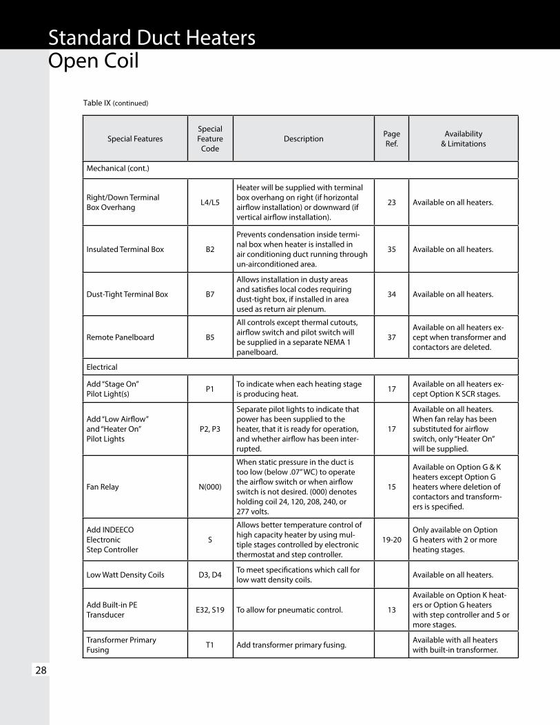
Table IX (continued)
Special FeaturesSpecialFeature
CodeDescription Page
Ref.Availability
& Limitations
Mechanical (cont.)
Right/Down TerminalBox Overhang L4/L5
Heater will be supplied with terminal box overhang on right (if horizontal airflow installation) or downward (if vertical airflow installation).
23 Available on all heaters.
Insulated Terminal Box B2
Prevents condensation inside termi-nal box when heater is installed in air conditioning duct running through un-airconditioned area.
35 Available on all heaters.
Dust-Tight Terminal Box B7
Allows installation in dusty areas and satisfies local codes requiring dust-tight box, if installed in area used as return air plenum.
34 Available on all heaters.
Remote Panelboard B5
All controls except thermal cutouts, airflow switch and pilot switch will be supplied in a separate NEMA 1 panelboard.
37Available on all heaters ex-cept when transformer and contactors are deleted.
Electrical
Add “Stage On”Pilot Light(s) P1 To indicate when each heating stage
is producing heat. 17 Available on all heaters ex-cept Option K SCR stages.
Add “Low Airflow”and “Heater On”Pilot Lights
P2, P3
Separate pilot lights to indicate that power has been supplied to the heater, that it is ready for operation, and whether airflow has been inter-rupted.
17
Available on all heaters. When fan relay has been substituted for airflow switch, only “Heater On” will be supplied.
Fan Relay N(000)
When static pressure in the duct is too low (below .07” WC) to operate the airflow switch or when airflow switch is not desired. (000) denotes holding coil 24, 120, 208, 240, or 277 volts.
15
Available on Option G & K heaters except Option G heaters where deletion of contactors and transform-ers is specified.
Add INDEECOElectronic Step Controller
S
Allows better temperature control of high capacity heater by using mul-tiple stages controlled by electronic thermostat and step controller.
19-20Only available on Option G heaters with 2 or more heating stages.
Low Watt Density Coils D3, D4 To meet specifications which call for low watt density coils. Available on all heaters.
Add Built-in PETransducer E32, S19 To allow for pneumatic control. 13
Available on Option K heat-ers or Option G heaters with step controller and 5 or more stages.
Transformer PrimaryFusing T1 Add transformer primary fusing. Available with all heaters
with built-in transformer.

Standard Duct HeatersOpen Coil
29
Table IX (continued)
Special FeaturesSpecialFeature
CodeDescription Page
Ref.Availability
& Limitations
Electrical (cont.)
Delete Transformer
Allows control circuit to be obtained from source outside the heater or, when line voltage is equal to control voltage, directly from power lines within the heater.
16
Only available on Option G heaters. Must be specified if control voltage is not 120 or 24 volts. Customer must specify control volts.
Delete Transformer & Contactors Allows for control of heater directly
using load carrying thermostats. 16
Available only on single stage, single-phase, Option G heaters with KW not exceeding the following.
TransformerSecondary Fusing T3
External fused and grounded trans-former secondary for Class II 24 volt control circuits.
Available on all heaters.
Additional UserControl CircuitVoltage
Heater control circuit transformer sized for additional user VA. A control terminal block is furnished for field connection.
Available on all heaters. Consult factory for 1 week or 72 hour heater avail-ability.
Delete Disconnect Allows for use of field installed dis-connecting means. (Must be within sight of the heater.)
16 Available on all heaters.
Fused DisconnectSwitch Q1
Door interlocking disconnect with line fusing for heaters loads up to 48 amps or less.
16 Available on all heaters.
Linear LimitAutomatic ResetThermal Cutout
Z/Z1
Automatic reset linear limit thermal cutout wired in series with the disc type automatic reset to provide redundant primary over temperature protection.
14
Available on all heaters. Exact airflow direction must be specified U3, U4, U5 or U6.
Add Fuses for HeatersRated 48 Amps or Less F1
Allows for addition of one set of fuses to low amperage heaters that do not need internal fusing to meet UL and NEC requirements
16
Available on all heaters whose KW is lower than or equal to the following. (Other heaters include fus-ing as standard):
Voltage 120 277Max. KW 1.8 4.1
Line KW (at 48 amps)Volts 1 Phase 3 Phase120 5.7 -208 9.9 17.2240 11.5 19.9277 13.2 -480 23.0 39.9

Standard Duct HeatersOpen Coil
30
Table X
Summary of Thermostats Available with Option G or K Heaters (No Thermostats are supplied on Option J Heaters)
† A thermostat or input must be specified with all Option K heaters and all Option G heaters with step controllers. Step controllers with 4-20 mA or 0-10 VDC will be furnished with proportional control.
www.indeeco.com 800-243-8162
Type of Thermostat
Used with
Control Option
CatalogNumber Comments
ROO
M
Pilot Duty
1 Stage G 1006998 (Fig.11) Rated for 30 volts max. Offered with Duct Heater Selection
1 Stage G 1023721 (Fig. 12) Digital Display, Rated for 30 volts max. Special Ordered
2 Stage G 1007030 (Fig. 13) Digital Display, Rated for 30 volts max.
2 or 3 Stage G 1023723 (Fig. 14) Programmable with Digital
Display, Rated for 30 volts max.
† Proportional Electronic
GorK
SCR Controlled or 2-4 Stages 1016941 (Fig. 16) Vernier Controlled or over 4 Stages 1007101 (Fig. 15)
With Option G, can be used only when step controller is also specified
DU
CT
Pilot Duty
1 Stage G 1023953 (Fig. 18) Rated for 277 volts max.
2 Stage G 1007044 (Fig. 19) Rated for 277 volts. max.
† Proportional Electronic
GorK
SCR Controlled or 2-4 Stages 1016942, 1016941 (Fig. 21)
Vernier Controlled or over 4 Stages 101083, 101068 (Fig. 20)
With Option G, can be used only when step controller is also specified.
† No Thermostat(Special inputs for controller or SCR when customer supplied thermostat is used)
GorK
———
2200 ohm Input135 ohm Input4-20 mA Input0-10 VDC Input

Standard Duct HeatersOpen Coil
31
A job specification can be prepared by using the following information. Simply darken the applicable circles. Material which is part of the basic specification has already been darkened. Additional copies of this specification guide are available from your local INDEECO representative.
● 1. Duct heaters shall be INDEECO ○ Type QUA Standard Slip-in Heaters ○ Type QUZ Standard Flanged Heaters
● 2. Approvals – Heaters and panelboards (if required) shall meet the requirements of the National Electrical Code and shall be listed by Underwriters Laboratories for zero spacing between the duct and combustible surfaces and for use with heat pumps and air conditioning equipment.
● 3. Heating elements shall be open coil, 80% nickel, 20% chromium, Grade A resistance wire. Type C alloys containing iron or other alloys are not acceptable. Coils shall be machine crimped into stainless steel terminals extending at least 1” into the airstream and all terminal hardware shall be stainless steel. Coils shall be supported by ceramic bushings staked into supporting brackets.
● 4. Heater frames and terminal boxes shall be corrosion resistant steel. Unless otherwise indicated, the terminal box shall be NEMA 1 construction and shall be provided with a hinged, latching cover and multiple concentric knockouts for field wiring.
● 5. All heaters shall be furnished with a disc type, automatic reset thermal cutout for primary over-temperature protection. All heaters shall also be furnished with disc type, load carrying manual reset thermal cutouts, factory wired in series with heater stages for secondary protection. Heat limiters or other fusible overtemperature devices are not acceptable.
● 6. Heaters shall be rated for the voltage, phase, and number of heating stages indicated in the schedule. All three-phase heaters shall have equal, balanced, three-phase stages. All internal wiring shall be stranded copper with 105°C insulation and shall be terminated in crimped connectors or box lugs.
● 7. Terminal blocks shall be provided for all field wiring and shall be sized for installation of 75°C copper wire rated in accordance with NEC requirements.
● 8. Heaters shall be furnished, either with the Control Option specified in the schedule and described below, or with the specific components listed in the schedule.
○ Option G – Thermal cutouts, airflow switch, contactors, fuses (if over 48 amps), control circuit transformer (where required) and built-in, snap-acting, door interlocked disconnect switch.
○ Option J – Thermal cutouts, airflow switch, PE switches, contactors (where required), fuses (if over 48 amps), control circuit transformer (where required), and built-in snap-acting door interlocked disconnect switch.
○ Option K – Thermal cutouts, airflow switch, contactors (where required), SCR (with step controller if heater draws over 96 amps three-phase or 192 amps single-phase), fuses (if over 48 amps), control circuit transformer, and built-in snap-acting door interlocked disconnect switch.
○ 9. When specified in the schedule, or below, heaters will be supplied with the following Special Features: ○Airflowswitchfornegativepressureoperation○ Insulatedterminalbox○Dust-tightterminalbox○Stainless steel frame and terminal box○Aluminized steel frame and terminal box○ Insulated duct construction for slip-in heaters (>1” ≤6”
thick lining)○Unheated section (≤6” terminal pin)○Pressure plate○Protective screen(s); ○one side ○ both sides○Controls mounted in NEMA 1 remote panelboard○Deletion of transformer○Deletion of transformer and contactor○Transformer primary fusing○Transformer secondary fusing (Class II)○ Additional user control circuit voltages (specify user VA)○Deletion of disconnect switch○Fused disconnect switch (≤ 48 amps)○Fusing for heaters rated 48 amps or less○ “Low Airflow” pilot light○ “Heater On” pilot light○Each “Stage On” pilot light(s)○Fan relay (instead of airlfow switch)○Fan relay (in additional to airflow switch)○Step controller○Linear limit automatic rest thermal cutout○25 watts per square inch resistance coils○35 watts per square inch resistance coils○Built-in PE transducer
○ 10. When specified in the schedule, or below, heaters shall be supplied with the following thermostats:○Pilot duty single stage room thermostat○Pilot duty digital display single stage room thermostat○Pilot duty two stage digital display room thermostat○Pilot duty two or three stage programmable with
digital display room thermostat○Proportional electronic room thermostat○Pilot duty single stage duct thermostat○Pilot duty two stage duct thermostat○Proportional electronic duct thermostat with set point
adjuster○Special inputs (135 ohms, 2200 ohms, 4-20 mA,
0-10 VDC)
QUA/QUZ – Sample Specification

Special ApplicationsAir Conditioning & Air Handling Units – For more than 55 years, INDEECO has been supplying special heaters for use in air handling and air conditioning equipment (Figure 49). A wide range of special construction techniques has been developed to insure proper operation as well as easy installation, either in the OEM’s plant or in the field. These heaters typically fall into one of the categories described on the following pages.
32
Multi-Zone or Dual Duct Heaters – These heaters are designed for installation inside multi-zone or dual duct air conditioning equipment, where the airflow is highly variable and unevenly distributed (Figure 51). These heaters use coils derated to approximately 25 watts per square inch (3.8 watts per square cm) of wire surface area (approximately one half normal watt density). Low density coils run cooler, and thus, provide longer life under these stringent operating conditions.
These heaters are supplied with fully proportional SCR control or with many heating stages to insure that no more heat is being supplied than is absolutely necessary. Each heater stage is spread over the entire face area to take advantage of all available airflow.
A perforated pressure plate is factory-installed on the air inlet side of the heater to make the airflow as uniform as possible. Linear limit thermal cutouts protect against serious overheating anywhere along the length of the heater.
When the heater must be installed entirely within the unit, only thermal cutouts are built into the heater, a remote panel is required for controls. When the terminal box can be external, heaters are available with a wide range of built-in controls.
Modular Construction – The heater is designed to match adjacent air handling unit components, such as fans, cooling sections, filter boxes, etc. (Figure 50). Special construction is used so that the heater mounts adjacent to other components; the heater becomes simply one module of the air handling unit assembly. Unheated sections are provided where there is little or no airflow, such as the area blocked by an adjacent cooling coil header. Pressure plates can be provided to insure uniform airflow, when the heater must be installed adjacent to the fan. Buffer sections can be furnished to space the heating coils away from temperature sensitive components or to help assure uniform airflow.
Figure 51.
Custom Duct Heaters
www.indeeco.com 800-243-8162
Figure 49.
Figure 50.

33
www.indeeco.com 800-243-8162
Custom Duct Heaters
Round Duct Construction – INDEECO manufactures UL listed open coil duct heaters specifically designed for installation to commercially rated round ducts. Heaters are available for installation to spiral single and double wall or snap-lock round sheet metal ducts with inside diameters of 6, 8, 10, 12, 14, 16, 18, 20, 22, 24, 26 and 28 inches. Two square to round male galvanized steel transitions, Figure 53, are supplied for field installation to the inlet and outlet of the duct heater. The transitions are attached directly to the flanges of the heater and to the round duct using sheet metal screws (see Figure 52). The INDEECO transitions have been approved by UL to provide uniform airflow across the open coil elements to avoid hot spots, which could affect the performance of the heater.
Railway and Subway Applications – Tough rail car industry standards have been developed to overcome the severe vibration, shock, high operating voltages, and voltage swings routinely encountered. For more than 35 years, INDEECO has built heaters to meet these standards, using heavy gauge corrosion resistant steel frames and oversized coil and terminal support bushings (Figure 56).
Variable Air Volume (VAV) Units – To serve the fast moving and very competitive VAV market, INDEECO has developed a fully computerized design and construction system, which enables us to ship substantial volumes of heaters in a wide variety of sizes, ratings, and control options quickly. This system was patterned after our methods of designing and producing standard duct heaters, modified to solve the problems unique to the VAV industry. Slip-and-drive sheet metal connections, control packages tailored to VAV systems, and special techniques for fan interlocks are some of the features designed for this market (Figure 55).
Marine Duty – Only INDEECO offers a UL Listed duct heater which is also ABS Approved and meets U.S. Coast Guard Requirements for shipboard use (Figure 54).
Figure 52. Open Coil heater with round duct transitions.
Figure 53. Square to round sheet metal transitions.
Figure 55.
Figure 54.Figure 56.
Square Duct Heater Height
Square Duct Heater Width
Inside Round Duct Diameter

Duct Heaters for Wet, Dusty and Corrosive Areas
INDEECO offers a wide selection of custom built electric duct heater designs for outdoor, wet, dusty, and corrosive areas. Typical applications include use with roof top air handling equipment, in washdown areas such as food processing plants, wet and humid spaces near indoor swimming pools, and marine or casino boat applications including shipboard use.
Features:
• Disconnect switch with door interlock
• Manual reset thermal cutout
• Automatic reset thermal cutout
• Stainless steel frame
• Large diameter stainless steel finned tubular heating elements
• Heavy duty control transformer
• Fusing per NEC
• Airflow switch
• Stainless steel terminal hardware
Outdoor UL Listed 3R
34
A dust-tight terminal box (Figure 58) is available to meet local codes that require dust-tight construction for a heater installed above a false ceiling when the entire area is used as a return air plenum. It is also suitable for commercial or light industrial applications and to avoid dust accumulation inside the terminal box while a building is under construction.
These boxes are spot welded corrosion resistant steel, with all openings sealed. The hinged cover is gasketed and hold-down clamps are provided. (Note that this construction does not meet the more rigid requirements of NEMA 12 described below).
NEMA 12 Type Terminal Box
For heavy duty industrial applications involving both dust and oil, NEMA 12 construction is available on custom heaters (Figure 59). The all welded, stainless steel terminal box has a hinged, gasketed cover with hold-down clamps. Scru-tite hubs for line and power connections are included.
NEMA 4 Type Terminal Box
For weatherproof locations and washdown areas, such as food processing plants, a NEMA 4 Type construction is available. This all welded stainless steel enclosure is furnished with a hinged, gasketed cover and is provided with water-tight hubs for incoming power and control connections.
Outdoor type 3R heaters (Figure 57) are intended for outdoor use to provide a degree of protection against falling rain, sleet, and external ice formation. UL Listed 3R heaters can be used in most HVAC outdoor applications and indoors for protection against dripping water. Water-tight hubs for incoming power and control connections are furnished.
Figure 57.
Dust-tight Construction
Figure 59.
www.indeeco.com 800-243-8162
Custom Duct Heaters
Figure 58.
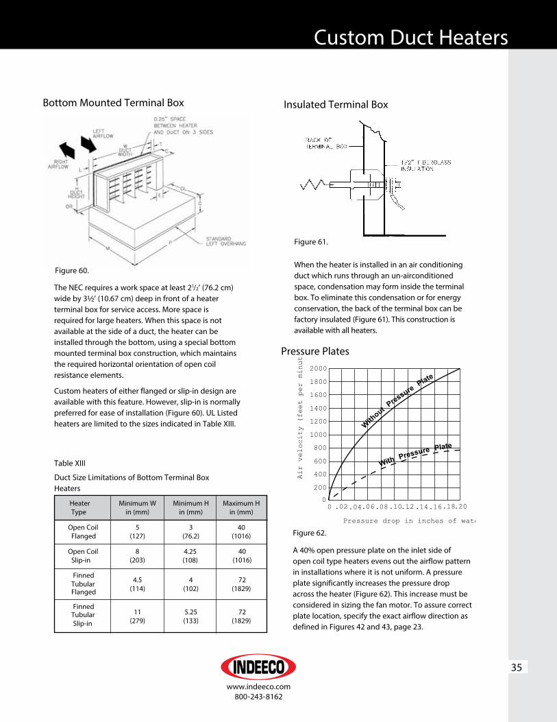
35
www.indeeco.com 800-243-8162
Custom Duct Heaters
The NEC requires a work space at least 21/2’ (76.2 cm) wide by 3½’ (10.67 cm) deep in front of a heater terminal box for service access. More space is required for large heaters. When this space is not available at the side of a duct, the heater can be installed through the bottom, using a special bottom mounted terminal box construction, which maintains the required horizontal orientation of open coil resistance elements.
Custom heaters of either flanged or slip-in design are available with this feature. However, slip-in is normally preferred for ease of installation (Figure 60). UL Listed heaters are limited to the sizes indicated in Table XIII.
Figure 62.
When the heater is installed in an air conditioning duct which runs through an un-airconditioned space, condensation may form inside the terminal box. To eliminate this condensation or for energy conservation, the back of the terminal box can be factory insulated (Figure 61). This construction is available with all heaters.
Pressure Plates
Figure 60.
Bottom Mounted Terminal Box
Figure 61.
Insulated Terminal Box
A 40% open pressure plate on the inlet side of open coil type heaters evens out the airflow pattern in installations where it is not uniform. A pressure plate significantly increases the pressure drop across the heater (Figure 62). This increase must be considered in sizing the fan motor. To assure correct plate location, specify the exact airflow direction as defined in Figures 42 and 43, page 23.
Table XIII
Duct Size Limitations of Bottom Terminal Box Heaters
Heater Minimum W Minimum H Maximum H Type in (mm) in (mm) in (mm)
Open Coil 5 3 40 Flanged (127) (76.2) (1016)
Open Coil Slip-in
Finned
4.5 4 72 Tubular (114) (102) (1829) Flanged
Finned Tubular 11 5.25 72
Slip-in (279) (133) (1829)
8 (203)
4.25(108)
40(1016)
0 .02.04.06.08.10.12.14.16.18.20
Pressure drop in inches of wate
Air velocity (feet per minut
WithoutPressurePlate
WithPress
ure Plate
2000
1800
1600
1400
1200
1000
800
600
400
2000

Protective screens protect personnel from accidental contact with electrically hot open coil elements and prevent large airborne contamination from reaching the elements (Figure 63). The 3/8” (9.5mm) wire mesh screen may be mounted on both sides of the heater. Finned tubular duct heater construction may be more appropriate for these applications.
Unheated Sections
36
All INDEECO slip-in heaters are suitable for use in ducts lined with up to 1” (25.4 mm) of interior insulation. Extended terminals and the design of the thermal cutout system make standard slip-in heaters suitable for such installations without any deterioration in performance or life. Be sure that the duct dimensions specified are those inside the duct lining.
For slip-in heater applications where the insulation is more than 1” (25.4 mm) thick or where flanged heaters are required, the special constructions illustrated in Figures 65 and 66. Dimensions inside the insulation must be specified as well as the insulation thickness.
Protective Screens Construction For Lined Ducts
INDEECO custom heaters can be supplied with unheated sections, either open or blocked off (Figure 64). Such constructions are particularly helpful when the heater frame must extend through an area with little or no airflow to maintain accessibility to the terminal box. For example, a heater next to a cooling coil should have extended terminal pins so no heat is generated adjacent to the cooling coil header. Most constructions are available with a UL label.
Figure 66. Installation of slip-in heater where insulation is more than 1” (25.4 mm) thick
Figure 64.
Figure 65. Installation of flange type heater in lined duct
www.indeeco.com 800-243-8162
Custom Duct Heaters
Figure 63.

37
www.indeeco.com 800-243-8162
Custom Duct Heaters
This option for custom flanged heaters, allowing installation with conventional HVAC slip-and-drive connections, offers the rugged and secure mounting of a flanged heater, yet requires less installation labor than a slip-in heater. It is particularly useful when other equipment in the duct system uses slip-and-drive connections, as the contractor can standardize throughout (Figure 67).
By using INDEECO’s slip-and-drive construction in variable air volume (VAV) units, the manufacturer can offer the same standard VAV box for electric heat, hot water heat, or no heat.
Remote PanelboardWhen specifying remote panelboards (Figure 68), we recommend the following changes in control and safety components to insure the safety of the installation and to minimize the field labor costs.
• Contactors – Use disconnecting controlling contactors which break all ungrounded lines. Thus, when heat is not being called for, all terminals in the heater will be dead.
• Pilot Switch – Add a dead front pilot switch to the heater terminal box to make it safe for servicing by simply tripping the pilot switch. This shuts off power to the heater circuits through the disconnecting contactors in the panel.
• Fuses – Built-in fusing for each panelboard will be in accordance with UL and NEC requirements.
Except for SCR’s, which are mounted through the panelboard side wall, control components are mounted on a sub-panel. Labeled terminal blocks are provided for all field wiring, both in the panel and in the heater. Knockouts and wiring gutter spaces are supplied in all panelboards.
NEMA 1 panels are made from heavy gauge steel, welded and painted (as required), and are provided with a lock and key. Wall mounting, flush mounting, or floor mounting on legs are available.
NEMA 3R type panelboards for outdoor use are UL Listed. These are intended for outdoor use to provide protection against falling rain, sleet, and external ice formation.
NEMA 4 and NEMA 12 panelboards for outdoor, dusty, and oil atmospheres are also available, as well as explosion-proof panels furnished with cast aluminum enclosures.
All standard type QUA and QUZ heaters are available with remote panels. Panels for these standard heaters are available in NEMA 1 wall mounting only. Fusing, disconnecting contactors, and a heater-mounted pilot switch, all as described above, are supplied.
Slip-and-Drive Construction
Figure 68.
Figure 67.

Minimum & Maximum Duct DimensionsAlthough there is no limitation on the maximum size of custom heater assemblies, individual UL Listed heaters must meet the following minimum and maximum requirements (see tables below).
UL Listed custom heaters are also available in virtually any KW rating. However, heaters are restricted to maximum KW ratings based on the square feet of heated area.
38
INDEECO has built individual duct heaters for space heating applications ranging from 0.1 KW to over 900 KW, multi-section units with up to 2000 KW in one assembly, and face areas as large as 40’ wide x 14’ high. Exact dimensional and KW limits can be determined by contacting your local INDEECO representative.
Figure 69. Slip-in Duct Heater Figure 70. Flanged Duct Heater
Table XIV
Open Coil Custom Heaters
Table XV
Finned Tubular Custom Heaters
Slip-in Type Flanged Type in (mm) in (mm)
Minimum Duct Width (W)
5.25 (133) 5 (127)
Minimum Duct Height (H)
4.25 (108) 3 (76)
Maximum Duct Width (W)
240 (6100) 240 (6100)
Maximum Duct Height (H)
120 (3050) 120 (3050)
Slip-in Type Flanged Type in (mm) in (mm)
Minimum Duct Width (W)
4.75 (121) 4.5 (114)
Minimum Duct Height (H)
5.25 (133) 4 (102)
Maximum Duct Width (W)
175 (4450) 175 (4450)
Maximum Duct Height (H)
120 (3050) 120 (3050)
www.indeeco.com 800-243-8162
Custom Duct Heaters

39
Custom Duct Heaters
A job specification can be prepared by using the following information. Simply darken the applicable circles. Material which is part of the basic specification has already been darkened. Additional copies of this specification guide are available from your local INDEECO representative.● 1. Duct heaters shall be INDEECO: Type XUB Custom Slip-in Heater Type ZUB Custom Flanged Heater● 2. Approvals – Heaters and panelboards (if required) shall meet the requirements of the National Electrical Code and shall be listed by Underwriters Laboratories for zero space between the duct and combustible surfaces and for use with heat pumps and air conditioning equipment.● 3. Heating elements shall be open coil, 80% nickel, 20% chromium, Grade A resistance wire. Type C alloys containing iron or other alloys are not acceptable. Coils shall be machine crimped into stainless steel terminals extending at least 1” into the airstream and all terminal hardware shall be stainless steel. Coils shall be supported by ceramic bushings staked into supporting brackets.● 4. Heater frames and terminal boxes shall be corrosion resistant steel. Unless otherwise indicated, the terminal box shall be NEMA 1 construction and shall be provided with a hinged, latching cover and multiple concentric knockouts for field wiring. ● 5. All heaters shall be furnished with a disc type, automatic reset thermal cutout for primary overtemperature protection. All heaters shall also be furnished with disc type, load-carrying manual reset thermal cutouts, factory wired in series with heater stages for secondary protection. Heat limiters or other fusible overtemperature devices are not acceptable.● 6. Heaters shall be rated for the voltage, phase, and number of heating stages indicated in the schedule. All three-phase heaters shall have equal, balanced, three-phase stages. All internal wiring shall be stranded copper with 105°C insulation and shall be terminated in crimped connectorsor box lugs.● 7. Terminal blocks shall be provided for all field wiring and shall be sized for installation of 75°C copper wire, rated in accordance with NEC requirements.● 8. Heaters shall be furnished, either with the Control Option specified in the schedule and described below, or with the specific components listed in the schedule.○ Option G – Thermal cutouts, airflow switch, contactors, fuses (if over 48 amps), control circuit transformer (where required) and built-in snap-acting door interlocked disconnect switch.○Option J – Thermal cutouts, airflow switch, PE switches, contactors (where required), fuses (if over 48 amps), control circuit transformer (where required) and built-in snap-acting door interlocked disconnect switch.
○ Option K – Thermal cutouts, airflow switch, contactors (where required), SCR (with step controller and contactors, if heater draws over 96 amps, three-phase or 192 amps single-phase), fuses (if over 48 amps), control circuit transformer (where required), and built-in snap-acting door interlocked disconnect switch.○ 9. When specified in the schedule, or below, heaters will be supplied with the following Special Features:○ Airflow switch for negative pressure operation○ Insulated terminal box○ Dust-tight terminal box ○Special terminal box construction○NEMA1 ○UL3R ○NEMA12 ○NEMA4 ○NEMA4X
○Stainless steel frame and terminal box○Aluminized steel frame and terminal box○Insulated duct construction for slip-in heaters○Unheated section○Pressure plate○Protective screen(s); ○ one side ○both sides○Controls mounted in remote panelboard○NEMA1 ○UL3R ○NEMA12 ○NEMA4 ○NEMA4X
○Deletionoftransformer○Delectionoftransformerandcontactor○Transformerprimaryfusing○Transformersecondaryfusing(ClassII)○Additionalusercontrolcircuitvoltage(specifyuserVA)○Deletionofdisconnectswitch○Fuseddisconnectswitch(≤48amps)○Fusingforheatersrated48ampsorless○“LowAirflow”pilotlight○“HeaterOn”pilotlight○“Overtemperature”pilotlight○Each“StageOn”pilotlight(s)○Fanrelay(insteadofairflowswitch)○Fanrelay(inadditiontoairflowswitch)○Stepcontroller○Linearlimitautomaticrestthermalcutout○25wattspersquareinchresistancecoils○35wattspersquareinchresistancecoils○Built-inPEtransducer○RoundDuctConstruction○10. When specified in the schedule, or below, heaters shall be supplied with the following thermostats:○Pilot duty single stage room thermostat○ Pilot duty digital display single stage room
thermostat○ Pilot duty two stage digital display room thermostat○ Pilot duty two or three stage programmable with
digital display room thermostat○Proportional electronic room thermostat○ Pilot duty single stage duct thermostat○ Pilot duty two stage duct thermostat○ Proportional electronic duct thermostat with set point
adjuster○ Special inputs (135 ohms, 2200 ohms,
4-20 mA, 0-10 VDC)
Open Coil Custom Heater – Sample Specification

A job specification can be prepared by using the following information. Simply darken the applicable circles. Material which is part of the basic specification has already been darkened. Additional copies of this specification guide are available from your local INDEECO representative.● 1. Duct heaters shall be INDEECO: Type TFXU Custom Slip-in Heater Type TFZU Custom Flanged Heater● 2. Approvals – Heaters and panelboards (if required) shall meet the requirements of the National Electrical Code and shall be listed by Underwriters Laboratories, for zero spacing between the duct and combustible surfaces, and for use with heat pumps, and air conditioning equipment.● 3. Heating elements shall consist of coil, 80% nickel, 20% chromium, Grade A resistance wire, precisely centered in a stainless steel tube filled with granular magnesium oxide. A stainless steel fin is to be helically wound onto the tube. Elements are to be furnished with mounting flanges, making them individually removable through the terminal box.● 4. Heater frames and terminal boxes shall be corrosion resistant steel. Unless otherwise indicated, the terminal box shall be NEMA 1 construction and shall be provided with a hinged latching cover and multiple concentric knockouts for field wiring. ● 5. All heaters shall be furnished with triple overtemperature protection. A disc type and linear, automatic reset thermal cutout are included for primary overtemperature protection. All heaters must also be furnished with a linear type manual reset thermal cutout with backup contactors (as required). For secondary overtemperature protection, heat limiters or other fusible overtemperature devices are not acceptable.● 6. Heaters shall be rated for the voltage, phase, and number of heating stages indicated in the schedule. All three-phase heaters shall have equal balanced three-phase stages. All internal wiring shall be stranded copper with 105°C insulation and shall be terminated in crimped connectors or box lugs.● 7. Terminal blocks shall be provided for all field wiring and shall be sized for installation of 75°C copper wire rated in accordance with NEC requirements.● 8. Heaters shall be furnished either with the Control Option specified in the schedule and described below or with the specific components listed in the schedule.
Option G – Thermal cutouts, airflow switch, contactors, fuses (if over 48 amps), control circuit transformer (where required) and built-in snap-acting door interlocked disconnect switch.
40
Option J – Thermal cutouts, airflow switch, PE switches, contactors (where required), fuses (if over 48 amps), control circuit transformer (as required), and built-in snap-acting door interlocked disconnect switch.
Option K – Thermal cutouts, airflow switch, contactors (where required), SCR (with step controller if heater draws over 96 amps three-phase or 192 amps single-phase), fuses (if over 48 amps), control circuit transformer (where required) and built-in, snap-acting, door interlocked disconnect switch.
9. When specified in the schedule, or below, heaters will be supplied with the following Special Features:
Airflow switch for negative pressure operation Insulated terminal box Dust-tight terminal box Special terminal box construction○NEMA 1○UL3R ○NEMA 12 ○NEMA 4 ○NEMA 4XStainless steel frame and terminal boxAluminized steel frame and terminal boxInsulated duct construction for slip-in heatersUnheated sectionControls mounted in remote panelboard○NEMA1 ○UL3R ○NEMA12 ○NEMA4 ○NEMA4X Deletion of transformer Deletion of transformer and contactor Transformer primary fusingTransformer secondary fusing (Class II)Additional user control circuit voltage(specify user VA)
Deletion of disconnect switchFused disconnect switch (≤ 48 amps)Fusing for heaters rated 48 ampes or less)
“Low Airflow” pilot light “Heater On” pilot light “Overtemperature” pilot light Each “Stage On” pilot light(s) Fan relay (instead of airflow switch) Fan relay (in addition to airflow switch) Step controller Built-in PE transducer
10. When specified in the schedule, or below, heaters shall be supplied with the following thermostats:
Pilot duty single stage room thermostatPilot duty digital display single stage room thermostat
Pilot duty two stage digital room thermostat Pilot duty two or three stage programmable with digtial display room thermostat
Proportional electronic room thermostat Pilot duty single stage duct thermostat Pilot duty two stage duct thermostat Proportional electronic duct thermostat with set point adjuster
Special inputs (135 ohms, 2200 ohms, 4-20 mA, 0-10 VDC)
Finned Tubular Custom Heater – Sample Specification
Custom Duct Heaters

41
Explosion-proof Duct Heaters
SafetyINDEECO explosion-proof ULTRA-SAFE™ and EP2 duct heaters are Factory Mutual (FM) and CSA Approved. The ULTRA-SAFE™ duct heater has the only standard product offering and features the industry’s lowest ignition temperature code rating, T3C, 320°F (160°C).
ExperienceThis catalog represents more than 75 years experience in industrial electric heating, our specialty since INDEECO was founded in 1929. INDEECO has more than 55 years experience with forced air comfort heating for hazardous locations.
Complete Product Line• Industry’s most comprehensive product line of
space heating equipment.
• Ratings up to 750 KW and 600 volts.
• Widest selection of built-in controls.
ApplicationsINDEECO Duct Heaters provide a clean, safe source of electric heat for comfort heating and freeze protection in hazardous locations where specific explosive gases or dusts are present, and environments where moisture and corrosion exist.
Use of Electric Heaters in Hazardous Areas
Electric heating equipment can be economically designed and safely used in hazardous areas, if the following special requirements are kept in mind.
1. The surface temperature of the electric heating equipment cannot exceed the ignition temperature of the hazardous atmosphere. To insure that the proper heater has been selected, it is essential that the correct NEC Ignition Temperature Code be specified (see Table XVI). If the Temperature Code selected is too high, the electric heating system may operate above the ignition point of the application, creating a potentially hazardous condition.
2. All arc and spark producing control devices must be isolated from the hazardous atmosphere. If it is not economically feasible to locate the control devices in a non-hazardous area, they must be housed in an enclosure that will withstand the pressure of a potential explosion from within the enclosure.
3. All electrical supply connections must be made according to the latest NEC and local code requirements for hazardous locations. This includes the requirement that conduit entering the enclosures must be provided with seals at the enclosure.
®�
www.indeeco.com 800-243-8162

Hazardous locations are those areas where a potential for explosion and fire exists due to the presence of flammable gases, vapors, pulverized dusts, or ignitable fibers in the atmosphere. Hazardous locations are created from the normal processing of volatile chemicals, gases, coal, grains, etc., or from the accidental failure of storage systems for these materials.
Both people and equipment in hazardous locations can be heated safely and economically with electric heat. Electric heating is typically much less expensive to install and maintain than comparable remote oil or gas fired heating systems.
42
ClassHazardous locations are divided into the three general classes of vapors/gases, dusts, and fibers.
Class I – Locations where the potential for explosion and fire exists due to the presence of flammable gases or vapors in the air. Typical Class I locations include: oil or natural gas drilling rigs, petroleum refining or pumping facilities, petrochemical plants, wastewater/ sewage treatment plants, solvent extraction plants, paint spraying booths, locations where open tanks or vats of combustible liquids are present, and storage areas for flammable materials.
Class II – Locations where the potential for explosion exists because of finely pulverized flammable dusts suspended in the atmosphere. Typical locations would include coal fired power plants, coal preparation/coal handling facilities, coal mines, grain elevators, flour and feed mills, packaging and handling of pulverized sugar, processing and storage of magnesium and aluminum powder.
Class III – This third classification is primarily a fire hazard where fibers or flyings suspended in the air create a hazard. This would include small pieces of thread like fiber, sawdust, lint, etc. Typical applications would include: textile mills, woodworking plants, cotton gins and cotton seed mills, and flax producing plants.
DivisionClass I, Class II, and Class III areas are further defined in terms of when the hazard occurs. Division 1 and Division 2 occurrences are summarized below:
Division 1 – If the hazard is expected to be present under normal conditions, such as in a production or processing facility, the occurrence is designated Division 1. The hazardous atmosphere may be present continuously, intermittently, periodically, or during normal repair or maintenance operations. Division 1 occurrences also include locations where a breakdown in the operations of processing equipment results in the release of hazardous vapors.
Division 2 – If the hazardous material is normally expected to be contained within a closed area, system or container and would enter the ambient atmosphere only under an abnormal failure, then it is referred to as a Division 2 occurrence.
National Electrical Code ClassificationArticles 500 through 516 of the National Electrical Code deal with the definition of hazardous areas and the use or design of electrical equipment used in these locations. Electric heating equipment for hazardous areas is specified based on the NEC Class, Division, Group, and Ignition Temperature.
Table XVI
Ignition Temperature
*All electrical equipment is designed not to exceed the ignition temperature of the hazardous atmosphere. The maximum surface temperature for electric heaters is defined by the NEC for each class as indicated above.
www.indeeco.com 800-243-8162
Explosion-proof Duct Heaters
Maximum SurfaceTemp. Of Heater*
NECIgnitionTemp.Code
°C °F
450 842 T1
300 572 T2
280 536 T2A
260 500 T2B
230 446 T2C
215 419 T2D
200 392 T3
180 356 T3A
165 329 T3B
160 320 T3C

43
Class II – Hazardous dust locations are divided into three groups based on their ignition temperature and electrical conductivity of the suspended particles.
Group E – Atmospheres containing metal dusts such as aluminum and magnesium.
Group F – Atmospheres containing coal, charcoal, or coke dusts.
Group G – Atmospheres with grain, flour, starch, combustible plastics, or chemical dusts.
Class III – Locations have no group definitions.
Explosion-proof Duct Heaters
GroupThe nature and explosive characteristics of the hazardous material is defined by the NEC group to which it is assigned.
Class I – Hazardous gas locations include chemicals and other materials that have been divided into four groups based on their ignition temperature and explosive characteristics. (Groups A, B, C and D)
Table XVII
The materials given are found in NEPA 497M, 1991 and NFPA 325, 1994.
CLASS I - HAZARDOUS GAS ATMOSPHERES CLASS I - HAZARDOUS GAS ATMOSPHERES
Ignition Temp. NEC Ignition Temp. NEC
Group Material °F °C Code Group Material °F °C Code
A Acetylene 581 305 T2 D Methyl Isobutyl Ketone 840 448 T2
B Acrolein (Inhibited) 428 220 T2D 2-Methyl-1-Propanol 780 415 T2
Butadiene 788 420 T2 (Isobutyl Alcohol)Ethylene Oxide 804 429 T2 Petroleum Naptha 550 288 T2AHydrogen 932 500 T1 Pyridine 900 482 T1Propylene Oxide 840 449 T2 Octanes 403 206 T3Propyl Nitrate 347 175 T3B Pentanes 500 260 T2B
C Acetaldehyde 347 175 T3B 1-Pentanol (Amyl Alchohol) 650 343 T2
Allyl Alcohol 713 378 T2 Propane 842 450 T1Carbon Monoxide 1128 609 T1 1-Propanol (Propyl Alchohol) 775 412 T2Cyclopropane 928 498 T1 2-Propanol (Isopropyl Alcohol) 750 399 T2Ethylene 842 450 T1 Propylene 851 455 T1Hydrogen Cyanide 1000 538 T1 Styrene 914 490 T1Hydrogen Sulfide 500 260 T2B Toluene 896 480 T12-Nitropropane 802 428 T2 Vinyl Acetate 756 402 T2Tetrahydrofuran 610 321 T2 Vinyl Chloride 882 472 T1
D Acetic Acid (Glacia) 867 463 T1 Xylenes 867- 463- T1
Acetone 869 465 T1 984 528Ammonia, Anhydrous 1204 651 T1 CLASS II - HAZARDOUS DUST ATMOSPHERESBenzene 928 498 T1 Ignition Temp. NEC
Butane 550 287 T2A Group Material °F °C Code
1-Butanol (Butyl Alcohol) 650 343 T2 E Aluminum, A422 Flake 608 320 T22-Butanol 761 405 T2 Calcium Silicide 1004 540 T1 (Secondary Butyl Alcohol) Manganese 464 240 T2CEthane 882 472 T1 Magnesium, Grade B, Milled 806 430 T2Ethanol (Ethyl Alcohol) 685 363 T2 F Charcoal 356 180 T3AEthyl Acetate 800 427 T2 Coal, Kentucky Bituminous 356 180 T3AEthylene Dichloride 775 413 T2 Coal, Pittsburgh Experimental 338 170 T3BGasoline (56-60 Octane) 536 280 T2A Pitch, Petroleum 1166 630 T1Gasoline (100 Octane) 853 456 T1 G Alkyl Ketone Dimer 320 160 T3CHeptanes 399 204 T3 Sizing CompoundHexanes 437 235 T2D Corn 482 250 T2CIsoprene 428 220 T2D Corn Starch, Modified 392 200 T3Isopropyl Ether 830 443 T2 Polyurethane Foam, 734 390 T2Methane (Natural Gas) 900- 482- T1 Fire Retardant
1170 632 Shellac 752 400 T2Methanol (Methyl Alcohol) 867 454 T1 Soy Flour 374 190 T3A3-Methyl-1-Butanol 662 350 T2 Sugar, Powdered 698 370 T2 (Isoamyl Alcohol) Sulfur 428 220 T2DMethyl Ethyl Ketone 759 404 T2 Wheat 428 220 T2D
Wood Flour 500 260 T2B

44
Engineering InformationNational Electrical Code Requirements for Duct Heaters In addition to the general requirements for hazardous areas on pages 42 and 43, the NEC also requires that all duct heaters have built-in protection against low airflow, primary and secondary overtemperature protection, and overcurrent protection for heaters drawing more than 48 amps. These safety features are provided with all INDEECO explosion-proof duct heaters.
Airflow RequirementsAirflow must be calculated to give the required temperature rise and to ensure sufficient airflow to prevent the thermal cutouts from tripping prematurely.
Required air volume to give the desired temperature rise for a given KW is determined by the formula: SCFM = KW x 3193/∆T where SCFM is airflow volume in Standard Cubic Feet per Minute and ∆T is temperature rise in °F.
Minimum air velocity for safe operation is determined by dividing the heater KW by the cross-sectional duct area: KW / Sq. Ft. = KW / (W x H / 144) where W and H are duct width and height in inches. For ULTRA-SAFE™ duct heaters, use the minimum W x H dimensions shown in the Heater Listing on page 48. Read the minimum velocity from the horizontal axis of Figure 72 for ULTRA-SAFE™ Duct Heater or Figure 73 for Series EP2 heaters.Airflow must be uniform over the face of the heater, and must be horizontal for all but Custom Explosion-proof Duct Heaters.
Horizontal airflow direction is defined in Figure 71.
Pressure drop through the heater can be determined by using Figure 74 for the ULTRA-SAFE™ duct heater.
Figure 71.
Figure 72.
KW P
er S
quar
e Fo
ot O
f Hea
t Exc
hang
er A
rea
Minimum air velocity required for ULTRA-SAFE™, feet per minute
(meters per minute)
8
6
4
20 200 400 600 800 (61) (122) (183) (244)
KW P
er S
quar
e Fo
ot O
f Are
a
Minimum air velocity required for EP2 feet per minute
(meters per minute)
Figure 73.
12
10
8
6
4
2
100 300 500 700 900 1100 1300 1500
100 200 300 400 500 600 700 800 900 1000 1200 1300 1400 1500
ULTRA-SAFE™Pressure Drop Curve
Figure 74.
Pres
sure
Dro
p, In
ches
Of W
ater
Air Velocity, Feet Per Minute
Explosion-proof Duct Heaters
□ G, H, J, K, L & M
N, P, O, R, S & T
U, V, W, X,Y & Z
Unit Size Codes▲ A, C, B, D, E & F
0
1
0.2
0.4
0.6
0.8
1.2
1.4
1.6
1.8
2.2
2.4
2.6
2.8
2
3

45
Explosion-proof Duct Heaters
Engineering developments at INDEECO have made electric duct heaters for hazardous locations readily available at affordable prices.
ULTRA-SAFE™• FM and CSA Approved for virtually all Class I and
Class II, Division 1 and 2 hazardous gas or dusty atmospheres
• Ignition temperatures as low as 320°F (160°C)
• Six standard sizes to fit a wide range of ducts
• Ratings up to 240 KW, 600 volts
Series EP2• FM and CSA Approved for Class I, Division 2
locations where a hazardous gas is occasionally present
• Ignition temperatures as low as 392°F (200°C)
• For ducts up to 240” (610 cm) wide by 120” (305 cm) high
• Ratings up to 1000 KW, 600 volts
Custom• Wider range of sizes than available in the other
two designs
• Vertical airflow
• Ratings up to 750 KW, 600 volts
Figure 75. ULTRA-SAFE™ Explosion-proof Duct Heater
Figure 76. EP2 Explosion-proof Duct Heater
Figure 77. Custom Explosion-proof Duct HeaterTable XVIII
Comparison Chart
Heater TypeKW andControlRange
Class and Division
NEC Ignition
Tempera-ture
Code
Special Considerations
Ultra-SafeTM
For hazardous gasor dust atmospheres.Fits ducts from 12”W x 12” H to75”W x 35” H.
Up to 240 KW
Single stageor SCR Control
Class I, Divisions 1 and 2,Groups B, C and D
Class II, Divisions 1 and 2,Groups E, F and G
T3C320 °F (160 °C)
• Fastest delivery of the three designs• Available for outdoor or wet locations• Corrosion resistant construction available• Horizontal airflow only• Not approved for shipborad use• Flanged mounting
Series EP2For Division 2 hazardous gases (hazard exists only occasionally).
Up to 1000 KW
Multi-stage or SCR Control
Class I, Division 2,Groups C and D
T3392 °F (200 °C)
• Available for outdoor or wet locations• May be less expensive than ULTRA-
SAFETM for larger KW designs• Horizontal airflow only• Approved for shipboard use• Flanged mounting
CustomDesigned for each project.Not FM or CSA Ap-provded.
Up to 750 KW
Multi-stageor SCR Control
Class I, Divisions 1 and 2,Groups C and D
Class II, Divisions 1 and 2,Groups E, F and G
T1842 °F (450 °C)throughT3B329 °F (165 °C)
• Horizontal or vertical airflow• Slip-in or flanged mounting• For ducts smaller than 12” x 12”• Available for outdoor or wet locations

www.indeeco.com 800-243-8162
Standard ConstructionHeat Exchanger has copper tubes with integral aluminum fins. Each unit undergoes hydrostatic testing at 350 psig, five times the pressure relief valve setting of 70 psig.
Heat Transfer Fluid is propylene glycol, a non-toxic, rust-inhibiting fluid that provides freeze protection to –49°F (–45°C). Its high heat transfer rate at 70 psig makes the heat exchanger suitable for gases that ignite at temperatures as low as 320°F (160°C). Thus every ULTRA-SAFE™ heater is rated for Temperature Code T3C.
Industrial Grade Heating Elements, built by INDEECO, are .475” (1.21 cm) diameter to provide extra insulation between the coil and sheath for high voltage protection.
Frame is heavy gauge galvanized steel, fitted with lifting lugs to facilitate installation.
Four Levels of Safety are provided on every heater: automatic and manual reset thermal cutouts, airflow interlock, and pressure relief valve.
Two thermal cutouts limit the heat transfer fluid temperature, assuring thermal safety. The automatic reset operates a “primary” magnetic contactor. The manual reset operates a separate backup magnetic contactor. If either cutout opens, the entire heater is de-energized.
A fan relay, acting as an airflow interlock, prevents the heater from being energized unless the fan starter is on.
The pressure relief valve on the heat exchanger opens only if the thermal cutout system fails to prevent excessive temperatures.
Standard Built-in Control Package includes the following components mounted in a cast aluminum explosion-proof enclosure:
• De-energizing control and back-up magnetic contactors.
• 24V control circuit transformer.
• Fan relay, supplied with 24V or 120V holding coil to match the fan starter coil voltage.
• Terminal blocks for field power and control wiring.
• Grounding terminal.
46
• Supplemental fusing for heaters drawing more than 48 amps.
InstallationComplete installation instructions are furnished with each heater. Following are some guidelines:
• The heater must be securely attached to external duct flanges.
• The heater must be adequately supported. If the duct flanges will not afford enough support, overhead hangers attached to the lifting lugs may be used for additional support.
• Each heater is suitable for a variety of duct sizes. See Table XIX on page 48 for maximum and minimum dimensions. Note that duct height and width can vary independently.
• Airflow must be horizontal. See page 44 for airflow requirements.
Figure 78. ULTRA-SAFE™ Mounting Configuration
Classes I and II, Division 1 and 2 Groups B, C, D, F and G Temperature Code T3C, 320°F (160°C)
Ratings Available • Up to 240 KW • Up to 600V
Attach hanger rods to structure capable of supporting the weight of the heater.
Ensure attachment allows for height adjustment so that heater is level along both axis.
All field conduit must be adequately supported and comply with all code requirements.
1” minimum range typical all the way around.
Maximum duct dimensions (WMax & HMax) should allow for 1” minimum flange all around.
Minimum duct dimensions (WMin & HMin) are same as heat exchanger dimensions.
®�
ULTRA-SAFE™
Explosion-proof Duct Heaters

47www.indeeco.com
800-243-8162
ULTRA-SAFE™
Explosion-proof Duct Heaters
Temperature ControlSingle Stage Control – For many lower KW applications, single stage on/off control is adequate. For higher KW ratings, solid-state SCR control is recommended.
Solid-State SCR Control – When temperature must be controlled precisely, or for larger KW heaters, built-in SCR’s manufactured by INDEECO are recommended. They are furnished with field-selected
inputs of 2200 or 135 ohms, 0-10 VDC, or 4-20 mA. SCR’s have zero-cross firing to eliminate radio frequency interference.
To meet FM and CSA requirements, multi-unit designs (up to four heating units in series) also have controls set at 80°F (27°C) to limit the inlet air temperature to all but the inlet unit. These limit controls prevent excessive temperatures at the heater outlet as the inlet air temperature rises.
Figure 80. Heater with SCR Control and Options D, L and P
Figure 79. Heater with Single Stage Control

Figure 81. 1 Heat Exchanger Module
Figure 82. 2 Heat Exchanger Modules
48
www.indeeco.com 800-243-8162
Table XIX
Standard Heater Listing
(1) Consult factory for availability of other maximum inside duct dimensions. (2) Use only Minimum W x H dimensions for minimum air velocity calculations (see page 44). (3) Depth and weights shown for catalog listed KW ratings. They will be greater for larger KW and non-catalog designs. (4) Duct height and width can vary independently of minimum and maximum dimensions.
Weight (3)lb (kg)
Depth (3)in (cm)
CatalogNumber
Inside Duct Dimensions(4) - in (cm)Unit Size KW RangeMin. Max.Code Fig. Minimum(2) W X H Maximum(1) W X H
227F30A227F30G227F30N227F30U227F30B227F30H227F30P227F30V227F30C227F30J227F30Q227F30W227F30D227F30K227F30R227F30X227F30E227F30L227F30S227F30Y227F30F227F30M227F30T227F30Z
AGNUBHPVCJQWDKRXELSYFMTZ
369
12369
12102030406
1218246
12182420406080
1020304020406080306090
120204060804080
12016060
120180240
12 X 12 (30.5 X 30.5)
16.5 X 16 (41.9 X 40.6)
21 X 21 (53.3 X 53.3)
24 X 12(61 X 30.5)
33 X 16(83.8 X 40.6)
42 X 21 (106.7 X 53.3)
18 X 24 (45.7 X 61)
22.5 X 28(57 X 71)
27 X 35(69 X 89)
34 X 24(86 X 61)
43 X 28 (109 X 71)
52 X 35(132 X 89)
8 (20)16 (41)24 (61)32 (81)12 (31)24 (61)36 (91)
48 (122)12 (31)24 (61)36 (91)
48 (122)8 (20)
16 (41)24 (61)52 (32)12 (30)24 (61)36 (91)
48 (122)12 (31)24 (61)36 (91)
48 (122)
130 (59)260( 118)680 (208)710 (332)150 (68)
300 (136)730 (331)770 (349)200 (91)
400 (181)860 (390)940 (426)260 (118)470 (213)970 (440)
1090 (494)300 (136)550 (249)
1080 (490)1240 (562)390 (177)730 (331)
1350 (612)1600 (726)
79A
79B
79A79A
81
82
ULTRA-SAFE™
Explosion-proof Duct Heaters

49
www.indeeco.com 800-243-8162
ULTRA-SAFE™
Explosion-proof Duct Heaters
Classes I and II, Division 1 and 2Groups B, C, D, F and GTemperature CodeT3C, 320°F (160°C)
®�
Table XX
Custom Options
Figure 83. Built-on Airflow Switch Figure 84. Built-on Disconnect Switch
Option Description Code
Corrosion ResistantConstruction
Stainless frame, coated heat exchanger, epoxy-coated NEMA 4X, 7, 9 terminal box, conduit and fittings. C
Built-OnDisconnect Switch
To meet NEC requirement for a disconnect at or within sight of the heater. (Not available for outdoor, washdown or Groups B, E, F, G) D
Built-on AirflowSwitch
An explosion-proof differential pressure switch replaces the fan relay. Use only for positive pressure inside the duct. (Not available for outdoor, washdown or Group B).
P
SupplementaryFusing For heaters drawing 48 amps or less. Fusing is standard above 48 amps. F
“Warning”Pilot Light Red light to indicate when a thermal cutout or airflow interlock has tripped. K
“Heater On”Pilot Light Green light indicates when there is power to the heater. L
DisconnectingMagnetic Contactors
Contactors that break all ungrounded lines replace standard de-energizing contactors. M
120 VoltControl Circuit
A 120V control transformer with one leg fused replaces the standard 24V trans-former. (Not available with solid-state SCR control.) V
NEMA 4Construction Explosion-proof box is gasketed for outdoor or wet locations. G
Group BConstruction
For Class I, Group B areas. Heater will be rated for Classes I and II;Divisions 1 and 2; Groups B, C, D, E, F and G. Z

50
How to Order1. Catalog No. or Size – Specify Catalog Number
from Table XIX on page 48.
2. KW Rating – Up to the maximum shown in Table XIX.
3. Heater Voltage and Phase
4. Temperature Control – Single Stage or SCR Control. If SCR Control, specify input signal.
5. Fan Relay Voltage – Specify 24 or 120 volt to match fan starter holding coil voltage.
6. Airflow Direction – Horizontal Right-Hand or Left-Hand airflow, as defined on page 44.
7. Maximum Inlet Air Temperature – Maximum of 80° F (27° C). If inlet air will be higher, consult factory.
8. Options – Select from ULTRA-SAFE™ Custom Option codes in Table XX.
Sample SpecificationA sample specification can be prepared by using the following information. A circle has been supplied so that you may darken those sections which you require. Material which is part of the standard ULTRA-SAFE™ Explosion-proof Duct Heater specification has already been darkened.
● 1. Electric explosion-proof duct heaters shall be INDEECO ULTRA-SAFE™ Series, of the KW rating, voltage, phase, duct size and airflow direction specified in the schedule. They shall be Factory Mutual and CSA Approved for:
● Class I, Divisions 1 and 2, Groups C and D; Class II, Divisions 1 and 2, Groups E, F, and G Ignition Temperature Code No. T3C, 320°F (160°C).
Class I, Divisions 1 and 2, Groups B, C, and D; Class II, Divisions 1 and 2, Groups E, F, and G Ignition Temperature Code No. T3C, 320°F (160°C).
● 2. Duct heaters shall have automatic and manual reset thermal cutouts for redundant overtemperature protection, fan relay for airflow interlock, de-energizing controlling and backup magnetic
contactors, 24 volt control circuit transformer, terminal blocks for field wiring and supplementary fusing for heaters over 48 amps. Controls shall be housed in a NEMA 7, 9 cast aluminum enclosure.
● 3. The heat exchanger shall be liquid-to-air design, utilizing a copper tube core with integral aluminum fins. Nontoxic, inhibited, propylene glycol heat transfer fluid shall be used that provides freeze protection down to –49°F (–45°C). Pressure relief valve setting to be 70 psig. The heat exchanger shall include industrial grade INDEECO electric heating elements.
● 4. Duct heaters shall be furnished with the control option indicated below (select one):
Single stage on/off control with field installed thermostat.
Solid-state control with built-in zero-cross switching SCR and field installed thermostat.
5. The following options are to be included:
Corrosion resistant stainless steel construction with iridite coated heat exchanger, epoxy coated NEMA 4X, 7, 9 terminal box, conduit and fittings.
Built-on disconnect switch (not available for outdoor, washdown or Group B, E, F constructions).
Supplementary fusing for heaters drawing less than 48 amps.
Warning pilot light to indicate overtemperature or no airflow.
“Heater On” pilot light to indicate power to the heater.
Disconnecting magnetic contactors.
Built-on airflow switch in place of the fan relay (not available for outdoor, washdown or Group B construction).
120 volt transformer in place of 24 volt transformer (not available with solid-state SCR control.
NEMA 4, 7, 9 gasketed control box for wet locations.
Supply Line
Tag No. KW Volts Phase
Stages Special Features
DH1 10 480 3 1 18 12 Built-on disconnect switch
DH2 15 480 3 1 36 18 Corrosion resistant DH3 75 480 3 1 48 24 construction
Typical ULTRA-SAFE™ Duct Heater Schedule
Duct Dimensions (Inches) W (Width) H (Height)
ULTRA-SAFE™
Explosion-proof Duct Heaters

51www.indeeco.com 800-243-8162
Series EP2Explosion-proof Duct Heaters
Standard ConstructionGalvanized Sheet Metal Frame includes external flanges for field mounting and an element terminal box. Terminals are factory-connected to control safety components in an integral cast aluminum explosion-proof box.
Three Levels of Safety are provided on every heater: automatic and manual reset thermal cutouts, plus a fan interlock relay.
The automatic reset cutout, operating through the temperature control system, is the primary protector. The manual reset operates a separate backup magnetic contactor, independent of the temperature control system. The fan interlock relay prevents the heater from being energized, unless the fan starter is on.
Standard Built-in Control Package includes the following components mounted in a cast aluminum explosion-proof enclosure:
• De-energizing control and backup magnetic contactors.
• 24 volt control circuit transformer.
• Fan relay for heater/fan airflow interlock. Supplied with 120V or 24V coil to match the fan starter.
• Terminal blocks for field power and control wiring.
• Grounding terminal.
• Supplemental fusing for heaters drawing more than 48 amps.
Industrial Grade Heating Elements, built by INDEECO, are .475” (1.21 cm) diameter to provide extra insulation between the coil and sheath for high voltage protection. Stainless steel fins are helically wound onto the stainless steel sheath.
Control OptionsTwo standard control options are available:
Staged Control – Either single or multi-staged through a step controller, which may be built-in or remotely mounted. Each three-phase stage has a multiple of three elements to balance the electrical load.
Solid-State SCR Control – When temperature must be controlled precisely, built-in SCR’s are recommended. They are furnished with field-selected inputs of 2200 ohms, 135 ohms, 0-10 VDC, or 4-20 mA. SCR’s have zero-cross firing to eliminate radio frequency interference.
InstallationComplete installation instructions are furnished with each heater. The following are some guidelines:
• The heater must be attached to external duct flanges.
• The heater must be adequately supported. If the duct flanges will not afford enough support, use overhead hangers for additional support.
• Airflow must be horizontal. See page 44 for airflow requirements.
Class I, Division 2 Groups C and D Temperature Code T3, 392°F (200°C)
Ratings Available • Up to 240 KW • Up to 600V
®�
Figure 85. Series EP2 Explosion-proof Duct Heaters

52
Table XXI
Custom Options
Figure 86. Dimensional Drawing for EP2
www.indeeco.com 800-243-8162
Option Description Code
Built-inStep Controller
For two through ten heating stages. Input is field-selected at 2200 ohms, 135 ohm, 0-10 VDCs, or 4-20 mA. B
Built-OnDisconnect Switch
To meet NEC requirement for a disconnect at or within sight of the heater. (Not available for outdoor or washdown) D
Built-on AirflowSwitch
An explosion-proof differential pressure switch replaces the fan relay. Use only for positive pressure inside the duct. (Not available for outdoor or washdown). P
SupplementaryFusing For heaters drawing 48 amps or less. Fusing is standard above 48 amps. F
“Warning”Pilot Light Red light to indicate when a thermal cutout or airflow interlock has tripped. K
“Heater On”Pilot Light Green light indicates when there is power to the heater. L
DisconnectingMagnetic Contactors
Contactors that break all ungrounded lines replace standard de-energizing contactors. M
120 VoltControl Circuit
A 120V control transformer with one leg fused replaces the standard 24V trans-former. V
NEMA 4Construction Explosion-proof box is gasketed for outdoor or wet locations G
Series EP2Explosion-proof Duct Heaters
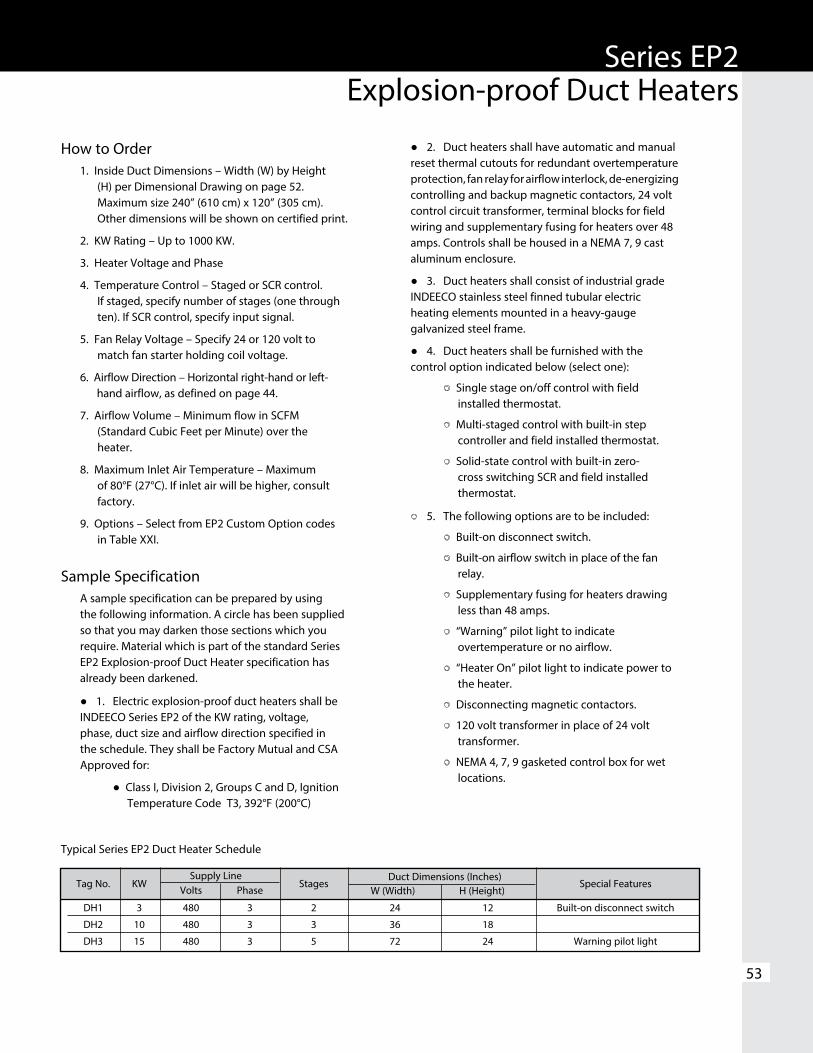
53
Series EP2Explosion-proof Duct Heaters
How to Order1. Inside Duct Dimensions – Width (W) by Height
(H) per Dimensional Drawing on page 52. Maximum size 240” (610 cm) x 120” (305 cm). Other dimensions will be shown on certified print.
2. KW Rating – Up to 1000 KW.
3. Heater Voltage and Phase
4. Temperature Control – Staged or SCR control. If staged, specify number of stages (one through ten). If SCR control, specify input signal.
5. Fan Relay Voltage – Specify 24 or 120 volt to match fan starter holding coil voltage.
6. Airflow Direction – Horizontal right-hand or left-hand airflow, as defined on page 44.
7. Airflow Volume – Minimum flow in SCFM (Standard Cubic Feet per Minute) over the heater.
8. Maximum Inlet Air Temperature – Maximum of 80°F (27°C). If inlet air will be higher, consult factory.
9. Options – Select from EP2 Custom Option codes in Table XXI.
Sample SpecificationA sample specification can be prepared by using the following information. A circle has been supplied so that you may darken those sections which you require. Material which is part of the standard Series EP2 Explosion-proof Duct Heater specification has already been darkened.
● 1. Electric explosion-proof duct heaters shall be INDEECO Series EP2 of the KW rating, voltage, phase, duct size and airflow direction specified in the schedule. They shall be Factory Mutual and CSA Approved for:
● Class I, Division 2, Groups C and D, Ignition Temperature Code T3, 392°F (200°C)
● 2. Duct heaters shall have automatic and manual reset thermal cutouts for redundant overtemperature protection, fan relay for airflow interlock, de-energizing controlling and backup magnetic contactors, 24 volt control circuit transformer, terminal blocks for field wiring and supplementary fusing for heaters over 48 amps. Controls shall be housed in a NEMA 7, 9 cast aluminum enclosure.
● 3. Duct heaters shall consist of industrial grade INDEECO stainless steel finned tubular electric heating elements mounted in a heavy-gauge galvanized steel frame.
● 4. Duct heaters shall be furnished with the control option indicated below (select one):
Single stage on/off control with field installed thermostat.
Multi-staged control with built-in step controller and field installed thermostat.
Solid-state control with built-in zero-cross switching SCR and field installed thermostat.
5. The following options are to be included:
Built-on disconnect switch.
Built-on airflow switch in place of the fan relay.
Supplementary fusing for heaters drawing less than 48 amps.
“Warning” pilot light to indicate overtemperature or no airflow.
“Heater On” pilot light to indicate power to the heater.
Disconnecting magnetic contactors.
120 volt transformer in place of 24 volt transformer.
NEMA 4, 7, 9 gasketed control box for wet locations.
Supply Line
Tag No. KW Volts Phase
Stages Special Features
DH1 3 480 3 2 24 12 Built-on disconnect switch
DH2 10 480 3 3 36 18
DH3 15 480 3 5 72 24 Warning pilot light
Typical Series EP2 Duct Heater Schedule
Duct Dimensions (Inches) W (Width) H (Height)

www.indeeco.com 800-243-8162
ConstructionHeaters are generally constructed per Series EP2 (see page 57), except that element terminals as well as control components are built into a single cast aluminum explosion-proof enclosure.
Frame – Sized to fit the duct. Standard flanged design recommended to support heater weight. Slip-in also available, if necessary, to match other equipment. Galvanized steel standard; stainless steel optional.
Control Enclosure – NEMA 7, 9 cast aluminum box with hinged cover houses controls and element terminals. Weatherproof construction optional.
Heating Elements – Heavy wall, large diameter stainless steel finned tubular elements, individually removable for servicing.
SCR Temperature Control – SCR’s with zero-cross firing provide precise proportional control. SCR’s also minimize element operating temperatures for extra safety. Optional on/off single or multi-stage control also available.
Overtemperature Protection – Thermocouple controllers measure element sheath temperature.
• Automatic reset control resets when temperature drops to a safe level.
• Manual reset control, with external button, provides back-up protection.
Fuses – Individual circuit fusing for heaters drawing over 48 amps to meet NEC requirements.
Airflow Interlock – Fan relay prevents heater operation, unless fan is energized. Optional built-in or remote explosion-proof airflow switch can be provided.
Magnetic Contactors – Furnished as required for temperature and safety controls.
Control Transformer – Furnished as standard with fusing as required.
54
Figure 88. Control Enclosure
Class I, Division 1 and 2 Groups C and D
Class II, Divisions 1 and 2 Groups E, F, and G
Although built to hazardous safety standards, these heaters are not FM or CSA Approved.
Figure 87. Custom Duct Heater
CustomExplosion-proof Duct Heaters

55
CustomExplosion-proof Duct Heaters
How to Order1. Construction Type – Standard flanged or
optional slip-in. See Figures 89 and 90.
2. Electrical Ratings – Line voltage, KW, Phase and Control Voltage.
3. Inside Duct Dimensions – Width and Height.
4. Temperature Control – Staged or SCR Control. If staged, specify number of stages (one through ten). If SCR control, specify input signal.
5. Airflow Direction –
• Horizontal (Right or Left).
• Vertical (Up or Down).
6. Airflow Volume – Minimum flow in SCFM (Standard Cubic Feet per Minute) over the heater.
7. Maximum Inlet Air Temperature – Maximum of 80°F (27°C). If inlet air will be higher, consult factory.
8. Classification of Hazardous Area – Class, Group, Ignition Temperature and NEC I.D. Code No.
9. Options – Select from EP2 Custom Option codes in Table XXI on page 52.
Sample SpecificationA sample specification can be prepared by using the following information. A circle has been supplied so that you may darken those sections which you require. Material which is part of the standard Custom Explosion-proof Duct Heater specification has already been darkened.
● 1. Electric explosion-proof duct heaters shall be INDEECO custom explosion-proof, the KW rating, voltage, phase, duct size, construction type and airflow direction specified in the schedule. They shall be approved for:
Class I, Divisions 1 and 2, Groups C and D, and NEC Ignition Temperature I.D. Code Number ________ (please specify).
Class II, Divisions 1 and 2, Groups E, F, and G, and NEC Ignition Temperature I.D. Code Number ________ (please specify).
● 2. Duct heaters shall have automatic and manual reset thermal cutouts for redundant overtemperature protection, fan relay for airflow interlock, de-energizing controlling and backup magnetic contactors, 120 volt control circuit transformer, terminal blocks for field wiring and supplementary fusing for heaters over 48 amps. Controls shall be housed in a NEMA 7, 9 cast aluminum enclosure.
● 3. Duct heaters shall consist of industrial grade INDEECO stainless steel finned tubular electric heating elements mounted in a heavy-gauge galvanized steel frame.
● 4. Duct heaters shall be furnished with the control option indicated below (select one):
Single stage on/off control with field installed thermostat.
Multi-stage control with built-in step controller and field installed thermostat.
Solid-state control with built-in zero-cross switching SCR and field installed thermostat.
5. The following options are to be included:
Built-on disconnect switch.
Supplementary fusing for heaters drawing less than 48 amps.
Warning pilot light to indicate overtemperature or no airflow.
“Heater On” pilot light to indicate power to the heater.
Disconnecting magnetic contactors.
Built-on airflow switch in place of the fan relay.
24 volt transformer in place of 120 volt transformer.
NEMA 4, 7, 9 gasketed box for wet locations.
Figure 89. Standard Flanged Heater Installation
Figure 90. Optional Slip-in Heater Installation

www.indeeco.com 800-243-8162
56
Typical Wiring Diagrams
Illustrated on these pages are typical wiring diagrams for INDEECO open coil and finned tubular duct heaters.
Wiring diagrams shipped with many heaters are semi-typical in nature, showing various alternates for certain compo-nents and illustrating Special Features which may not be supplied on the heater in question. However, check blocks on each wiring diagram are marked to indicate which of the alternates or Special Features apply. The wiring diagrams also indicate the appropriate field wiring gauges and the amp rating of any fuses provided.
Control Option G, Single Stage Three-Phase
Control Option G, Single Stage with Fan Relay,Three-Phase
Open Coil
Open Coil
Diagram-1
Diagram-3 Diagram-4
Diagram-2
Finned Tubular
Finned Tubular

57
Typical Wiring Diagrams
Control Option G, Multiple Stages, Single-Phase
Control Option G, Multiple Stages with Electronic Step Controller, Three-Phase
Control Option K, SCR, Three-Phase
Open Coil
Open Coil
Open Coil
Diagram-5
Diagram-7
Diagram-9
Diagram-6
Diagram-8
Diagram-10
Finned Tubular
Finned Tubular
Finned Tubular

Standard Control Options
58
Typical Wiring Diagrams
Control Option K, with a Proportional Room or Duct Thermostat, Three-Phase
Control Option K, SCR Vernier Control, Three-Phase
Control Option K, SCR Vernier Control, Remote Control Panel, Three-Phase
Open Coil
Open Coil
Open Coil
Diagram-11
Diagram-13
Diagram-15
Diagram-12
Diagram-14
Diagram-16
Finned Tubular
Finned Tubular
Finned Tubular

Standard Control Options
www.indeeco.com 800-243-8162
59
INDEECO Products
Industrial Unit Heaters • Ratings from 3 KW through 38 KW. • Stainless steel finned tubular heating elements. • Adjustable discharge louvers. • Bracket for ceiling or wall mounting. • Built-in controls. • cULus Listed.
TRIAD® Washdown and Corrosion Resistant Unit Heaters • Stainless steel construction with NEMA 4X enclosure. • Built-in controls. • Swivel mounting bracket. • Ratings up to 47 KW. • cULus Listed and ABS Approved.
Explosion-proof Unit Heaters • ULTRA-SAFETM EXP has industry’s lowest ignition
temperature code rating. • Class I & II, Divisions 1 & 2, Groups C, D, E, F & G. • Built-in controls. • Small, economical COMPACT designs up to 12 KW. • Factory Mutual (FM), CSA, ABS Approved.
Explosion-proof Convectors • Class I & II, Divisions 1 & 2, Groups B, C, D, E, F & G. • Ratings from 500 to 9,500 watts. • Sloped-top cabinet design. • Available with built-in controls. • Factory Mutual (FM), CSA, ABS Approved.

INDEECO Products
www.indeeco.com 800-243-8162
60
Comfort Heating ProductsForced -Air Heaters
• Cabinet unit heaters range from 2,000 to 24,000 watts. Units may be mounted on the floor, wall or ceiling, and can be recessed for wall or ceiling applications. Full line of optional features available.
• Commercial and architectural wall heaters available from 2,000 to 12,000 watts.
• Ceiling heaters for surface, T-Bar, or recessed mounting with voltage up to 480 VAC, 3-phase and up to 10,000 watts.
Baseboard Heaters• Heavy-duty baseboard heaters for commercial, architectural,
or industrial applications. Available in flat or sloped top design with a durable epoxy/polyester powder paint finish on a heavy gauge aluminum and steel cabinet. Sizes range from 300 to 4,000 watts.
• Architectural convectors provide large amounts of heat without the fan noise associated with the unit heaters. Can be floor or wall mounted, and fully recessed with a front warm air outlet.
Unit Heaters• Heavy-duty commercial unit heaters, offered to 50KW,
can be mounted horizontally or vertically. Each heater is available with both ceiling and wall mounting brackets for easy installation.

Industrial Engineering and Equipment Company (INDEECO) products are warranted against defects in workmanship, material, design, labeling and packaging. No other warranty, expressed or implied, written or oral, applies. No person other than an officer or the general manager of INDEECO is authorized to give any other warranty or assume any liability.
Warranty Period: This warranty is effective for eighteen months from the date of shipment of the product from INDEECO’s factory, or for twelve months from the date the product is first placed in service, whichever period lapses first.
Conditions of Warranty: INDEECO products must be installed, operated and maintained in accordance with INDEECO’s instructions. INDEECO is not liable for damage or unsatisfactory performance of the product resulting from accident, negligence, alteration, unauthorized repair, improper application or installation of the product, improper specifications or corrosion. INDEECO IS NOT LIABLE FOR ANY INCIDENTAL OR CONSEQUENTIAL DAMAGES. Claims against carriers for damage in transit must be filed by the purchaser with the carrier.
Remedy: The part or product in question should be returned, freight prepaid, to:
INDEECO 425 Hanley Industrial Court St. Louis, Missouri 63144 Attention: Return Materials Manager
If after receipt of the product and the claim, INDEECO finds to its reasonable satisfaction that the product is defective in workmanship, material, design, labeling or packaging, the product will be repaired or replaced or the purchase price refunded at INDEECO’s option. There will be no charge to the purchaser for parts or labor. Removal and reinstallation of the product, and shipment of the product to INDEECO for repair or inspection shall be at the purchaser’s risk and expense.
THE REPAIR, REPLACEMENT OR REFUND PROVIDED FOR IN THIS LIMITED WARRANTY IS THE EXCLUSIVE REMEDY OF THE PURCHASER. THIS WARRANTY IS EXPRESSLY IN LIEU OF ANY OTHER WARRANTIES, EXPRESSED OR IMPLIED, INCLUDING ANY WARRANTY OF MERCHANTABILITY OR FITNESS FOR A PARTICULAR PURPOSE. THERE ARE NO WARRANTIES WHICH EXTEND BEYOND THE TERMS OF THIS LIMITED WARRANTY.
Limited Warranty
s
INDUSTRIAL ENGINEERING & EQUIPMENT CO.425 HANLEY INDUSTRIAL COURT
ST. LOUIS, MO 63144314-644-4300
Fax: 314-644-5332www.indeeco.com
FOR YOUR NEAREST INDEECO REPRESENTATIVE CALL:
800-243-8162
10-1100-80-4 5M0609