e-GGRT Training Webinar on Reporting GHG Data for Subparts ...
74
1
Transcript of e-GGRT Training Webinar on Reporting GHG Data for Subparts ...

1

2

3
4

5

Before we can open the subpart C and D modules, we must select them on the subpart selection page. After checking the boxes for subparts C and D, we click save on the bottom of the screen.
Unselecting a subpart will cause all data that had been previously added in a subpart to be deleted. To prevent accidental deletion, a warning message will appear after unchecking a subpart.
6

After adding the subparts, they will appear on the Facility Overview page. To access the subpart C and D overview pages, we can click on the open buttons on the right side of the screen.
Next we will discuss when the subpart C and D modules should be used.
7

8

The subpart C reporting module is designed to fulfill the reporting requirements specified in subpartC f t 98C of part 98.
Facilities will report all emissions from stationary fuel combustion sources under the subpart C module.
9

The following sources are exceptions to reporting under the subpart C module:
Unit types that are listed in 40 CFR 98.30(b) are exempted from reporting emissions under subpart C.
Electricity generating units subject to subpart D will not use the subpart C reporting module, instead such units should use the subpart D module.
Combustion units that exhaust to a CEMS that monitors both combustion CO2 emissionsCombustion units that exhaust to a CEMS that monitors both combustion CO2 emissions and process CO2 emissions, and where the process CO2 emissions are reported under a separate subpart. In this situation, the emissions measured by the CEMS will be reported under the subpart in which the process emissions must be reported. For example, a cement kiln that has both process and combustion CO2 emissions monitored by the same CEMS, will have all emissions reported under subpart H.
Lastly, if a process unit calculates emissions according to another subpart and theLastly, if a process unit calculates emissions according to another subpart and the calculated emissions include combustion emissions, the rule may not require separate reporting of the combustion emissions. If that is the case, the combustion emissions should not be separately reported under subpart C. This only includes situations where the combustion emissions are explicitly included as process emissions calculated according to another subpart. If a facility contains both combustion and process units, and emissions are calculated separately, the combustion emissions would be reported under subpart C as required by the rule.
10

The subpart D module is similar to the subpart C module, but is designed to satisfy the specific reporting requirements of units subject to the requirements of subpart D.
Subpart D includes electricity generating units that are subject to the requirements of the Acid Rain Program, and any other electricity generating units that are required to monitor and report to EPA CO2 mass emissions year‐round according to 40 CFR part 75. For example, RGGI units.
Subpart D does not include electricity generating units that are not in the Acid Rain Program, and that do not report CO2 mass emissions year‐round according to 40 CFR Part 75. These sources should be reported under the subpart C module, as applicable.
11

Once the subpart C Module has been selected in e‐GGRT, the starting point in subpart C is to add a reporting configuration.
12

The subpart C reporting module revolves heavily around 6 different reporting options that are known as configurations in e‐GGRT. The reporting options, or configurations, refer to individual units or groups of units that are grouped together for the purposes of reporting under subpart C. The configurations provided in e‐GGRT are an incorporation of the different reporting options provided in 40 CFR 98.36.
13

This screen lists the six reporting configurations that are available in e‐GGRT. Next to each configuration type is the rule reference that describes each reporting option. For more information on the specific reporting options, please see the rule references provided. Additional information is also provided in the e‐GGRT reporting instructions.
14

For each configuration, there are two levels of emission reporting: there is a configuration‐level reporting requirement which is aggregated emissions numbers for a configuration and then there are fuel‐specific reporting requirements for each configuration. The exact requirements for emissions reporting will vary by configuration type.
If a configuration includes multiple units, no unit‐level emission reporting is required for that grouping.
A facility may have more than one type of configuration and multiple configurations of any type.
15

For each configuration, E‐GGRT provides two different, but required paths for reporting emissions under subpart C. The first path is configuration‐level emissions reporting. These emissions will be reported once for each configuration and the requirements will vary by configuration type.
The other path is that of fuel‐specific emission reporting. Emissions will be reported for each fuel combusted in the configuration and the requirements will vary by tier and by fuel typetype.
In the following screens we will show how to add a configuration of the type “Single Unit Using Tier 4”.
16

The starting point for adding a configuration is the Subpart C Overview page, which is shown on this slide. The Subpart C Overview page may be accessed by adding the subpart C source category and then opening it on the facility overview page. From the subpart C overview page, the first step is to click the “Add a Configuration” button located under the Configuration Summary table.
17
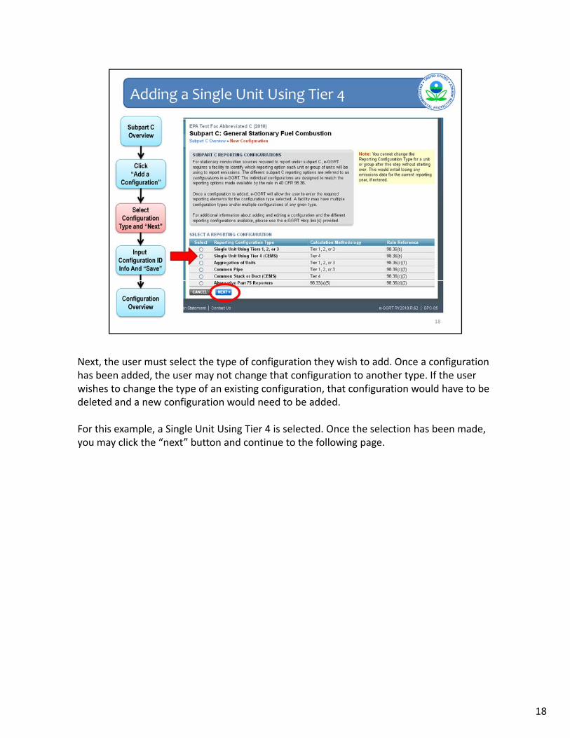
Next, the user must select the type of configuration they wish to add. Once a configuration has been added, the user may not change that configuration to another type. If the user wishes to change the type of an existing configuration, that configuration would have to be deleted and a new configuration would need to be added.
For this example, a Single Unit Using Tier 4 is selected. Once the selection has been made, you may click the “next” button and continue to the following page.
18

After the configuration type has been selected, certain identifying information must be entered. The required information will depend on the configuration type selected. Each configuration must be assigned a unique ID by the user.
Since this is a single unit configuration, the user must specify the unit type. E‐GGRT will provide a list of unit types that the user must select from. Also, as this is a Tier 4 configuration, the calculation methodology start and end date must be specified on this pagebe specified on this page.
Once the appropriate information has been entered, click save to finish adding the configuration.
19
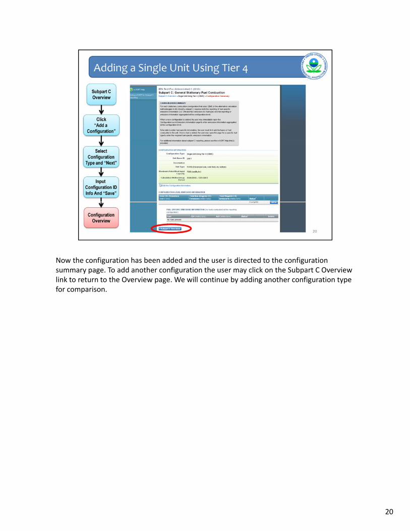
Now the configuration has been added and the user is directed to the configuration summary page. To add another configuration the user may click on the Subpart C Overview link to return to the Overview page. We will continue by adding another configuration type for comparison.
20

Having returned to the subpart C overview page, we can now see that the first configuration has been added in the configuration summary table. The identifying information of the configuration may be edited by clicking on the name of the configuration in the table.
To proceed with adding the new configuration, we click on the “Add a Configuration” link.
21

This time we select an “Aggregation of Units” option as the configuration type and click “Next”.
22

We can see that less information is required for this configuration than the previous type. Since it is a group of units, there is no requirement to identify the unit type. Also, since this configuration uses Tiers 1‐3 to calculate emissions, the methodology start date and end date information will be entered for each fuel and not for the configuration as a whole.
After the required information has been entered we hit “save”.
23

We are taken to the configuration overview page where we can see the newly added configuration. The layout of this page will be the same as for the previous configuration type, but the exact information displayed will vary slightly. We will discuss the requirements for entering emission information shortly. But first we will highlight one important difference with adding a Part 75 configuration.
24

Units using one of the calculation methodologies in 98.33(a)(5), referred to here as Part 75 configurations, have an additional requirement when identifying the configuration.
As a reminder, 98.33(a)(5) is an option available to units reporting under subpart C, that report heat input year‐round according to part 75. These are not units that report CO2 mass emissions year‐round to EPA and therefore are not included in subpart D.
On this screen the user must select the Part 75 methodology that was used to calculateOn this screen the user must select the Part 75 methodology that was used to calculate CO2 emissions. By selecting the method, the screen for entering emissions information will be updated accordingly.
Having now reviewed the steps for adding a configuration, we will walk through the steps for entering emissions information under Subpart C.
25

26

This page shows the screen flow of entering emissions information in subpart C.
The top path represents the process for entering emissions information at the configuration‐level. Starting on the configuration summary screen, the user will “Open” the configuration emissions screen. There is only one screen for entering the configuration‐level emissions for each configuration. Once that information has been entered, the user will save and return to the configuration summary page.
The vertical path represents the process for entering fuel specific emissions informationThe vertical path represents the process for entering fuel‐specific emissions information. Starting on the configuration summary screen, the user will first click “Add a fuel”. The user will next select the fuel type. Following the selection of fuel type, the user will pick the calculation methodology they used to calculate emissions. The selection of calculation methodology is only required when Tiers 1, 2, or 3 are used.
Following the calculation methodology selection, the user will be returned to the configuration summary page. In the bottom (and 3rd) step, the user will then “Open” eachconfiguration summary page. In the bottom (and 3 ) step, the user will then Open each fuel type and be taken to the screen to enter fuel‐specific emissions. There will only be one page for entering emissions information for each fuel type in the configuration.
27

For fuel‐specific emission reporting, the first requirement is to identify each fuel combusted in the configuration.
For fuels that use Tiers 1, 2, or 3 to calculate emissions, the user will input CO2, CH4, and N2O emissions for each fuel. If applicable, there will be additional requirements for specifying sampling frequency for HHV and carbon content determination, and requirements for reporting the use of missing data.
For configurations that use the Tier 4 or Part 75 configurations, the fuel‐specific reporting requirement is simply reporting CH4 and N2O emissions for each fuel type.
Let’s look at an example for the Tier 1, 2 or 3 case.
28

Starting on the configuration summary page for an aggregation of units configuration, the first step is to click the “Add a Fuel” link under the fuel‐specific emissions information table.
29

The first screen you see is for selecting the types of fuel combusted in the configuration. You may only select one fuel type at a time. The different fuel categories in Table C‐1 of Part 98 are drop down lists containing the fuel types listed in Table C‐1.
In addition to the fuel types listed in Table C‐1, you may add “other fuels or blends” using the link at the bottom of the page.
Once you have selected the fuel type you wish to add click save and you will be taken toOnce you have selected the fuel type you wish to add, click save and you will be taken to the next screen. For this example, we will select natural gas.
30

Shown is the calculation methodology selection screen for natural gas. The first step is to select the date range for which this methodology was used. This allows the user to identify when a change in calculation methodology occurred. If a methodology change did occur during the year, you would need to add this fuel twice, once for each calculation methodology period.
The second step is to select the calculation methodology used to calculate CO2 emissions for this fuel type The calculation methodologies listed correspond to the equationsfor this fuel type. The calculation methodologies listed correspond to the equations provided in the rule that could be used to calculate CO2 emissions for that fuel type.
The list is not intended to be prescriptive, and the user should refer to Part 98 to determine which calculation methodology they are required to use.
In this example we select Tier 1 (Equation C‐1). After selecting the calculation methodology, we will hit “save”.
31

After saving the methodology, we are returned to the configuration summary page. Natural gas is now listed as a fuel combusted in this configuration. At this point we can either add another fuel, or enter emissions for the added fuel. This time we will add a fuel not listed in Table C‐1.
32

This time, instead of selecting a fuel from the Table C‐1 lists, we will click the “Add an Other Fuel or Blend” link and be taken to the next page.
33

The define a new fuel type screen allows the user to name the new fuel type. It also requires the user to specify whether the fuel is an “other fuel type” or a “blend fuel type”. Blends contain multiple fuels listed in Table C‐1 and the exact composition of each fuel is unknown. If the relative portions of each fuel type in the blend are known, each fuel should be reported separately in e‐GGRT. The other fuel type should be selected when the fuel type has no mixture of fuels listed in Table C‐1 and the use of Tier 3 is required. In addition to specifying if a fuel is of the “blend” or “other” type, you will be required to specify whether the fuel is a gas liquid or solid Selection of the fuel type will determine whichwhether the fuel is a gas, liquid, or solid. Selection of the fuel type will determine which calculation methodologies are available for selection. For example, if an other gaseous fuel is selected, only Equation C‐5 will be available.
For more information on blended fuels, please see 40 CFR 98.34.
After entering a name and type, click “save” to proceed.
At this point we are now going to review the procedure for entering fuel‐specific emissions information.
34

Starting on the configuration summary page, we are now going to open the emissions reporting page for natural gas by clicking the “Open” link.
35

Here is the fuel‐specific emissions information page for natural gas when the equation C‐1 calculation methodology is selected. For fuels using equation C‐1, there are only 5 data fields. The first data field is for entering the CO2 emissions calculated according to equation C‐1. The second and third data fields are the CH4 and N2O emissions calculated according to equation C‐8 in metric tons of each gas. The fourth and fifth data fields are for reporting the CO2 equivalent emissions for CH4 and N2O.
Note that data inputs such as fuel consumption or heat input are not currently beingNote that data inputs such as fuel consumption or heat input are not currently being collected by e‐GGRT.
Also note that under the data input fields, there are links to calculation worksheets. We will go into further detail about the worksheets later in this presentation.
Saving the information will return you to the configuration summary page. On the next screen, we will review a different example in which the Tier 2 methodology for natural gas was selected.
36

The Tier 2 calculation methodology screen is similar to the Tier 1 screen, however two additional fields are present. These fields include reporting information on the use of missing data for the calculation of the High Heating Value for the fuel, and the frequency in which HHV determinations were made. In the next example we will look at the Tier 3 screen for natural gas.
37

Again, the basic information from the Tier 1 screen is included, but there are now additional reporting requirements for the carbon content and molecular weight information.
The input screen will be determined by the calculation methodology selected for the specific fuel type. Configurations that use the Tier 4 or Part 75 methodologies will also have slightly different reporting requirements for each fuel type and will be reviewed now.
38

Shown is what information would have to be entered for a fuel in a Tier 4 Configuration. The reporting fields on this page are for entering information on CH4 and N2O emissions only. All fuel types under the Tier 4 configuration type will require the same input information. Part 75 configurations in subpart C will be similar to Tier 4 configurations.
Having now viewed the fuel‐specific input screens, we will go into a little more detail on the equation worksheets provided through e‐GGRT.
39

Please note that if you used the Optional Calculation Spreadsheets during our Sandbox Testing opportunity earlier this year, those spreadsheets may have change since then. When e-GGRT opens for Live GHG reporting next week, be sure to download the most recent and corrected version of the calculation spreadsheets.
E-GGRT currently reflects the rule deferring reports of inputs to emission equations for direct emitters.
This means that in certain web forms in e-GGRT, you can view a required equation, but you will only enter the RESULT of that equation into e-GGRT. If you are using the XML upload option, the XML schema will also only include the RESULT of the equation as a data element.
The inputs of the equation are NOT currently collected by e-GGRT. EPA is providing OPTIONAL calculation spreadsheets that you can use to perform the calculations called for in the emission equations. These Microsoft Excel spreadsheets can be downloaded and opened on your own computer. Just click the hyperlink on the web-form to view and download the appropriate calculation spreadsheet for the equation you are working on. You can enter the data, including equation inputs, necessary to perform the calculation for the equation, and the spreadsheets will calculate the result for you. Once you have calculated the result, enter the result on to the e-GGRT web form.
E-GGRT will NOT collect the calculation spreadsheets and you do NOT need to submit them outside of e-GGRT. The use of these calculation spreadsheets is voluntary. The spreadsheets are meant to support reporters as they complete the e-GGRT online reporting process. You do not need to use EPA’s spreadsheets to perform the calculations for the emissions equations, but you do need to keep records of these calculations (under 40 CFR 98.3(g) and additional subpart-specific provisions). Whether or not you use the calculation spreadsheets provided by EPA. If you do not use the spreadsheets, you may choose to maintain copies to help meet your record-keeping requirements.
40

Moving on, the subpart C equation worksheets are accessible on the Fuel‐Specific Emissions screens. If there is a worksheet available to calculate a specific emission value, a link to the respective worksheet will be provided directly under the input field in e‐GGRT.
The subpart C equation worksheets include equations for calculating both CO2 and CH4/N2O emissions as applicable.
The worksheets available in e‐GGRT are listed on this slideThe worksheets available in e GGRT are listed on this slide.
The worksheets will calculate CO2 and CH4/N2O emissions for the Tier 1, 2, and 3 methodologies. The calculation worksheets will only calculate CH4 and N2O emissions for the Tier 4 and Part 75 methodologies.
For example, the Equation C‐1, C‐8 calculation worksheet will calculate CO2 emissions according to Equation C‐1, and CH4/N2O emissions according to Equation C‐8.
The C‐1, C‐8 worksheet is shown in the following slide.
41

The equation C‐1, C‐8 worksheet will have data fields where the user can enter the relevant information needed to calculate the emission values. For the C‐1, C‐8 worksheet, the user will enter the facility specific fuel consumption, default high heating value, and default emission factors for the fuel in the green cells. The emissions values will be calculated in the red‐bordered cells.
For your reference, Tables C‐1 and C‐2 are included in separate tabs in the worksheet.
Note that a separate worksheet is needed for each fuel type combusted in each configuration.
42

For configuration‐level emissions, the emissions reported will be aggregations across all units and all fuel types for a given configuration.
It is at the configuration‐level that the distinction between biogenic and fossil fuel CO2 emissions will be made.
For configurations that use Tier 4 or Part 75 reporting, the measured CO2 will be reported for the monitoring location at the configuration‐level In addition to CO2 emissions missingfor the monitoring location at the configuration level. In addition to CO2 emissions, missing data and other emissions information (as applicable) will be reported at the configuration level.
The exact requirements will vary by configuration type.
43

On the Configuration Summary page, we will click the “open” link on the right side of the configuration‐level emissions information table.
44

Here is the configuration‐level emissions reporting page for the aggregation of units configuration. The number of required elements is minimal for this configuration type. It is on this page that the distinction between biogenic and fossil fuel emissions will be made for this configuration. Once the required fields have been entered, hit “save” and you will be returned to the configuration summary page. The next screen will be an example of configuration‐level reporting for a Tier 4 configuration type.
45

Here is the top half of the configuration‐level emissions reporting page for a configuration of the type Single Unit Using Tier 4. The reporting fields shown on this slide all relate to CO2 emissions. The lower half of this e‐GGRT screen with the rest of the reporting elements can be seen on the next slide.
46

This page shows the lower half of the configuration‐level emissions reporting page for aSingle Unit Using Tier 4. In addition to the information on reporting CO2 emissions, there are input fields for reporting hours of substitute data use.
If section 98.33(e)(2) was used to calculate biogenic emissions, the reporter will also need to check the box and fill in a few additional reporting fields that will appear when the box is checked.
Once the information has been entered, the user will hit “Save” and return to the configuration summary page.
Moving on, we will now show a few examples for entering fuel‐specific emissions information.
47

We will now review the procedures for entering information for sources subject to subpart D.
48

Unlike subpart C, subpart D does not have unique configuration types. The reporting functionality of subpart D will closely mirror the Tier 4 and Part 75 reporting configurations in subpart C.
Like subpart C, subpart D requires both configuration‐level and fuel‐specific emissions reporting.
The primary distinction between units reported under subpart D will be the part 75The primary distinction between units reported under subpart D will be the part 75 methodology used to calculate CO2 emissions. The missing data reporting requirements will vary by the CO2 calculation methodology.
The four different CO2 calculation methodologies which the user may select from include: CEMS, Equation G‐1, Equation G‐4, and Low Mass Emitters.
49

We start on the Subpart D Overview page, which is shown on this slide and may be accessed from the facility overview page. The first step to add a subpart D source will be to click the “Add a Unit, Stack, or Pipe” link.
50

The Add Unit/Stack/Pipe page is essentially the same as the configuration identification page under subpart C.
For subpart D, the user must provide the unit, stack, or pipe ID representing the monitored location as reported under 40 CFR 75.64. The user must also specify the Part 75 methodology used to calculate CO2 emissions on this page.
The user must identify if this unit stack or pipe is in the Acid Rain Program Note that aThe user must identify if this unit, stack, or pipe is in the Acid Rain Program. Note that a start and end date must always be included. This does differ from Part 75 reporting, but explicit instructions are provided in e‐GGRT for selecting the appropriate start and end dates.
Having entered all of the required information, we will hit save.
51

The newly added source shows up under the source summary table. You may edit the identification by clicking on the source ID. To proceed to emission reporting, we will click the “open” link on the right side of the screen.
52

This screen should look familiar by now. It is essentially the same as the configuration summary screen for subpart C.
First we will enter the “configuration‐level” emissions information. We click “open” to proceed to the emissions information screen.
53
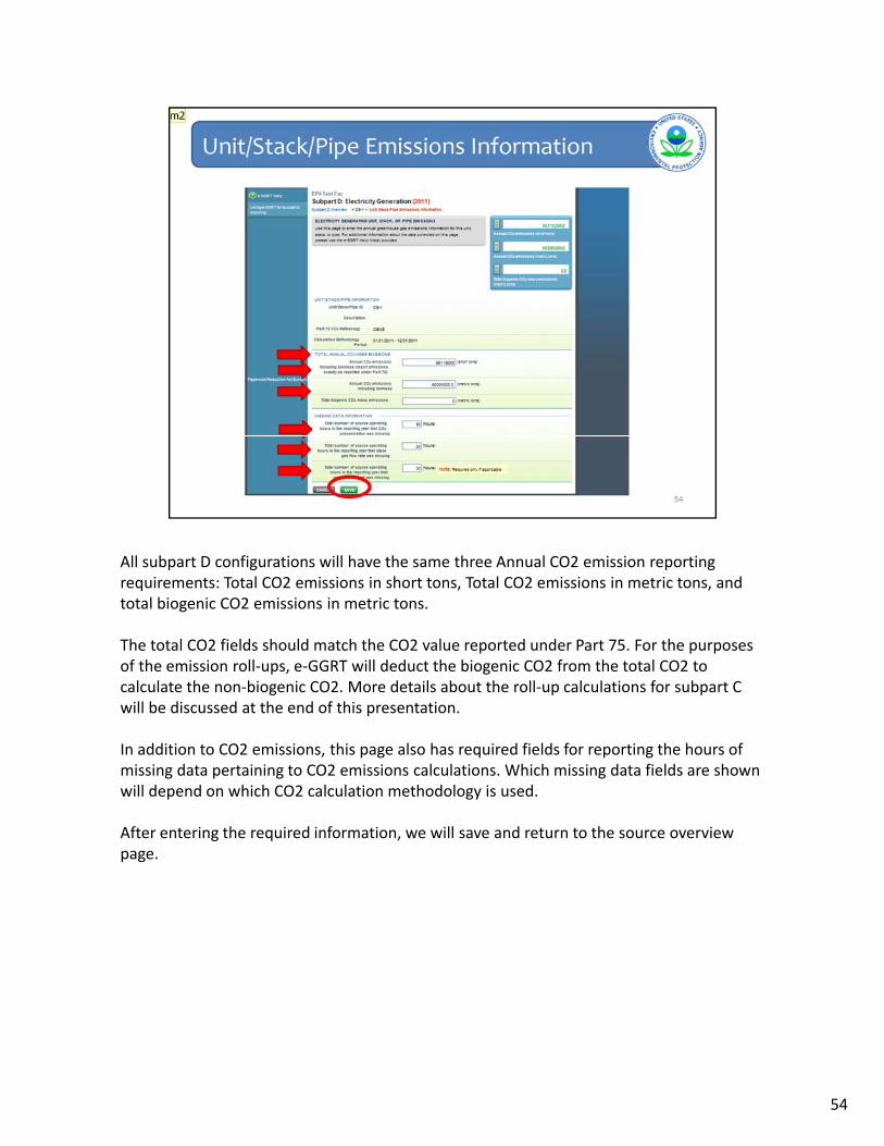
All subpart D configurations will have the same three Annual CO2 emission reporting requirements: Total CO2 emissions in short tons, Total CO2 emissions in metric tons, and total biogenic CO2 emissions in metric tons.
The total CO2 fields should match the CO2 value reported under Part 75. For the purposes of the emission roll‐ups, e‐GGRT will deduct the biogenic CO2 from the total CO2 to calculate the non‐biogenic CO2. More details about the roll‐up calculations for subpart C will be discussed at the end of this presentationwill be discussed at the end of this presentation.
In addition to CO2 emissions, this page also has required fields for reporting the hours of missing data pertaining to CO2 emissions calculations. Which missing data fields are shown will depend on which CO2 calculation methodology is used.
After entering the required information, we will save and return to the source overview page.
54

Having entered the configuration‐level emissions, we will now proceed to entering the fuel‐specific information.
As with the Tier 4 and Part 75 configurations in subpart C, the fuel‐specific reporting requirement is for CH4 and N2O emissions. The first step to identifying fuel specific information is to add a fuel. We will now click on the “add a fuel” button near the bottom of the screen.
55

The add a fuel screen is the same under subpart D as it is for subpart C. For this example we will select natural gas and hit “save”.
56

Natural Gas has now been added under the fuel table. To enter emissions for natural gas we will click the “open” button to the right of natural gas in the table.
57

Under subpart D, you are required to report the CO2 equivalent emissions of CH4 and N2O for each fuel combusted. This page will allow the user to enter those values. Clicking save will return us to the source summary page. After all of the fuel‐specific emissions values have been reported, the user will have entered all of the required information for the applicable unit, stack, or pipe in subpart D.
Next we will review some of the basic data validation errors that can occur when entering information in subparts C and Dinformation in subparts C and D.
58

59

Validation Types: e‐GGRT generates a variety of validation warning types, defined below:
Data Completeness: data required for reporting is missing or incomplete.Data Quality: data is outside of the range of expected values. The value you have provided is outside the EPA estimated range for this data element. Please double check this value and revise, if necessary. If you believe it to be correct, please submit the value as is. Screen Error: a data value or combination of data values prevents e‐GGRT from continuing to the next page Typically this will not appear on the Validation Report but instead will beto the next page. Typically, this will not appear on the Validation Report, but instead will be displayed on the data entry page at the time the error was created.
ID: Each validation message has a unique identifier. If you contact the e‐GGRT Help Desk with a question about a validation message, please include this unique identifier with your request.
60

Screen errors will occur when a data value has not been entered for a required field. You may not proceed to the next screen until a value has been entered in every field marked with a red asterisk. The fields marked with a red asterisk are necessary information for e‐GGRT and must be filled in before you can proceed to the next reporting screen. The absence of a “required field” indicator is not an indication that it is not a required reporting field in part 98.
We will now review how to check for data completenessWe will now review how to check for data completeness.
61

For an example of data completeness, we will illustrate what happens when a new fuel is added. At this point we have added the fuel, but not entered any emissions information.
Let’s see what is indicated on the subpart C Overview page at this time.
62

As you can see, on the Subpart C Overview screen, the warning sign on the right side of the screen indicates that one or more of the validation flags were triggered. If we click on the “view validation” link we will be taken to the validation report.
63

Several completeness entries will be shown for the data fields that currently have no information entered. To resolve these errors the user will need to enter information into each of the relevant fields. The unit and if applicable, fuel that are missing the information are identified. A link to the page containing the error is also provided with each error message.
64

To correct the validation errors we go back to the emissions information screen for natural gas. If we enter emissions numbers, but enter an exceedingly large CO2 emission value for natural gas, a range check error will be flagged.
65

The validation type will be shown as a “data quality” error and it will refer to the specific element that is outside the EPA estimated range for this value. Note that the range is set the same for all unit sizes and the error will likely only trigger in extreme cases in subpart C.
66
67

68

69
70

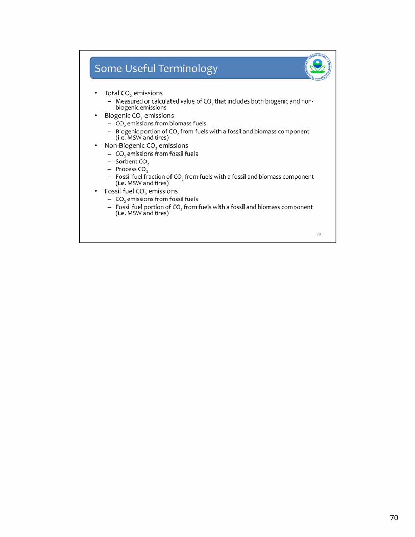
1. This is where the “rollup” is presented, which provides your total CO2 equivalent emissions (excluding biogenic) and biogenic CO2 emissions. The third total presented in the “roll up” is the quantity of CO2 equivalent for suppliers.
If you click on “view GHG details” you can see the underlying details on the metric tons of GHGs, by gas and by subpart, along with the GWP’s that go into the calculations.
71

Viewing the GHG details allows you to see the individual subpart components that were tallied into the Roll‐Up totals.
Note that the roll ups are in CO2 equivalent metric tons, in some cases this value will differ from the subpart data you entered because in the subpart you entered data for a gas with a higher Global Warming Potential than CO2.
72

EPA has also included a page called “Detailed Rollup Values”. This page shows the intermediate calculation steps for the roll‐up calculations. It shows the emissions reported for each fuel, and the breakdown of non‐biogenic CO2, biogenic CO2, and methane and nitrous oxide emissions for each unit, as calculated by e‐GGRT.
73

This concludes our training session for today. We hope this overview has provided you greater familiarity with navigating and entering information using the e-GGRT reporting tool.
Here are some additional links should you have further questions or if you would like to submit a question about the Greenhouse Gas Reporting Program.
74


![Subparts [Reserved] Subpart G-Canning and Canned Products](https://static.fdocuments.in/doc/165x107/6217482f4ff465780105f485/subparts-reserved-subpart-g-canning-and-canned-products.jpg)