E-Contents of Inspection& Quality Control Name Of Faculty ...
27
E-Contents of Inspection& Quality Control Name Of Faculty Vineet Kumar and Kapil Dev
Transcript of E-Contents of Inspection& Quality Control Name Of Faculty ...
E-Contents of
Inspection& Quality
Control
Name Of Faculty
Vineet Kumar
and
Kapil Dev
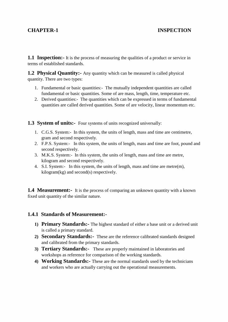
CHAPTER-1 INSPECTION
1.1 Inspection:- It is the process of measuring the qualities of a product or service in
terms of established standards.
1.2 Physical Quantity:- Any quantity which can be measured is called physical
quantity. There are two types:
1. Fundamental or basic quantities:- The mutually independent quantities are called
fundamental or basic quantities. Some of are mass, length, time, temperature etc.
2. Derived quantities:- The quantities which can be expressed in terms of fundamental
quantities are called derived quantities. Some of are velocity, linear momentum etc.
1.3 System of units:- Four systems of units recognized universally:
1. C.G.S. System:- In this system, the units of length, mass and time are centimetre,
gram and second respectively.
2. F.P.S. System:- In this system, the units of length, mass and time are foot, pound and
second respectively.
3. M.K.S. System:- In this system, the units of length, mass and time are metre,
kilogram and second respectively.
4. S.I. System:- In this system, the units of length, mass and time are metre(m),
kilogram(kg) and second(s) respectively.
1.4 Measurement:- It is the process of comparing an unknown quantity with a known
fixed unit quantity of the similar nature.
1.4.1 Standards of Measurement:-
1) Primary Standards:- The highest standard of either a base unit or a derived unit
is called a primary standard.
2) Secondary Standards:- These are the reference calibrated standards designed
and calibrated from the primary standards.
3) Tertiary Standards:- These are properly maintained in laboratories and
workshops as reference for comparison of the working standards.
4) Working Standards:- These are the normal standards used by the technicians
and workers who are actually carrying out the operational measurements.

1.5 Interchangeability:- the ability to select components for assembly at random and fit
them together within proper tolerances.
1.6 Objectives of inspection:-
1. Inspection separates defective components from non-defective ones and thus ensures
the adequate quality of products.
2. By doing so, it prevents the defective or sub-quality products from reaching the
assembly stage and, hence, the customer.
3. Inspection prevents further work being done on semi-finished products already
detected as spoiled.
4. It helps the companies in enhancing their reputation by maintaining quality standards.
1.7 Types of Inspection:-
Depending upon the method of production and location of the work, generally, the inspection
may be of the following kinds:
A. Based upon the Method of Inspection:
1. Remedial inspection
2. First-off inspection
3. In-process inspection
4. Operation inspection
5. Sampling inspection
6. Final inspection
7. Preventive inspection
B. Based upon Location:
1. Centralized or crib inspection
2. Decentralized or floor inspection
1.8 Study Of Factors Influencing The Quantity Of Manufacture:
1. Raw Material: The quality of finished products basically depends upon the
incoming raw material.
2. Skilled Manpower: Skilled manpower is needed to produce a quality work.
3. Machinery and Equipment: Modern machinery are required for best
quality of manufactured product.
4. Process: The process adopted should be right and according to the requirement.
5. Design: The quality is affected by the design of product.
6. Purpose: Quality varies according to the requirement.

CHAPTER- 2 MEASUREMENT AND GAUGING
2.1 Steel Rule:- It is made of tempered steel. It measures on the basic technique of
comparing an unknown length to the previously calibrated.
fig.2.1
2.2 Divider:- It is used for transferring dimensions, marking out curves and circles and
for doing general layout work. It may be firm-joint or spring type.
fig.2.2
2.3 Calipers :- Calipers is that measuring instrument is used for comparing linear
measurement against known dimension.
1) Outside caliper:- It is used for measurement measuring outside dimensions and
thickness.
fig.2.3.1

2) Inside caliper:- It is used for measuring inside dimensions.
fig.2.3.2
3) Odd leg or hermaphrodite caliper:- It is usedfor making line parallel the edge
of the work and for locating centre of cylindrical work.
fig.2.3.3
4) Transfer caliper:- It is used for measure recessed areas from which the legs of the
caliper can not be removed directly, But are collapsed after the dimension is
measured.
fig.2.3.4
2.4 Vernier Caliper:- It is a precision instrument which is used for measuring external
as well as internal diameter of the shafts, thickness of parts etc. to an accuracy of 0.02 mm.
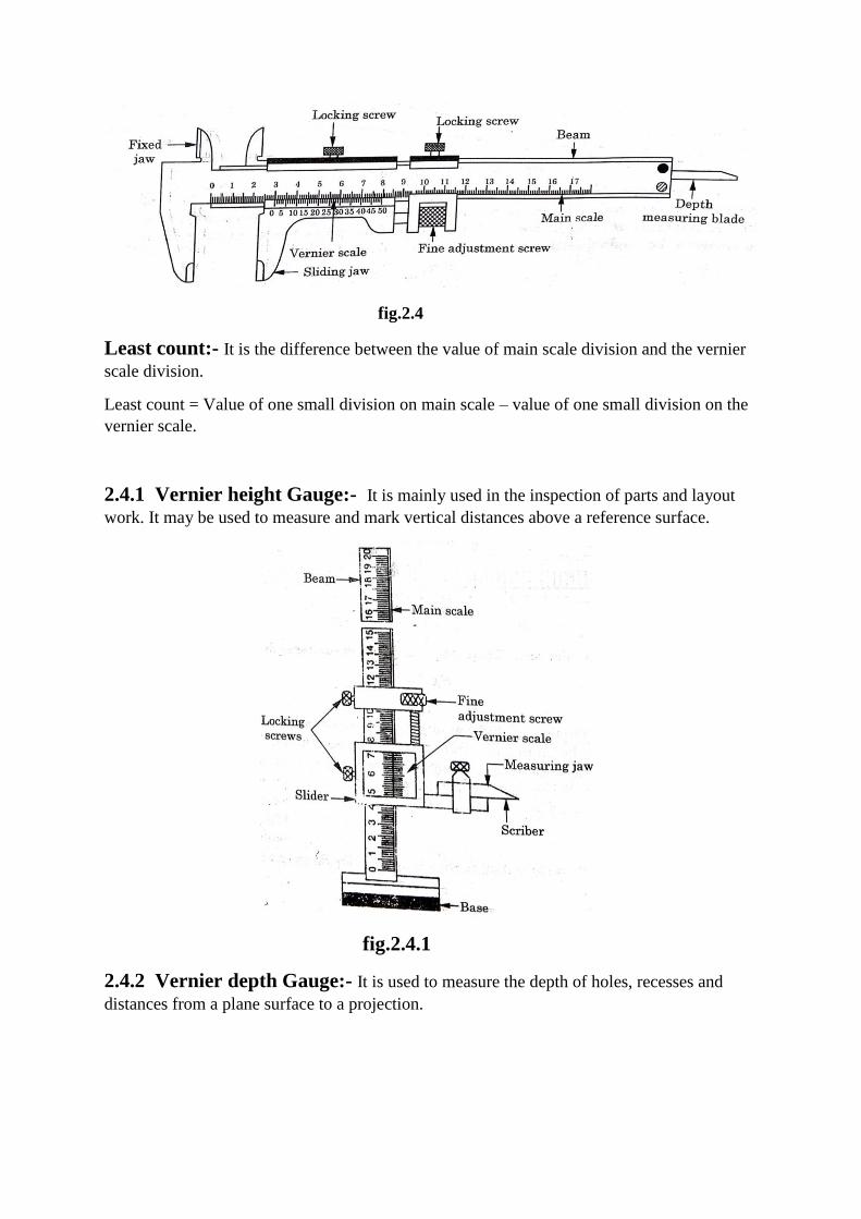
fig.2.4
Least count:- It is the difference between the value of main scale division and the vernier
scale division.
Least count = Value of one small division on main scale – value of one small division on the
vernier scale.
2.4.1 Vernier height Gauge:- It is mainly used in the inspection of parts and layout
work. It may be used to measure and mark vertical distances above a reference surface.
fig.2.4.1
2.4.2 Vernier depth Gauge:- It is used to measure the depth of holes, recesses and
distances from a plane surface to a projection.

fig.2.4.2
2.5 Micrometer:- These are precision measuring instruments. There are designed on the
principle of “screw and nut”.
1) Outside micrometer:- It is mainly used to measure the outside diameter of a job or
length of a small part. It can measure the dimension to an accuracy of 0.01mm.
fig.2.5.1
2) Inside micrometer:-It is used to measure the internal dimensions to an accuracy of
0.01mm. It works on the same principle as that of outside micrometer.
fig.2.5.2

3) Screw thread micrometer:- It is used to measure the pitch diameter of the screw
threads .It can measure with the accuracy of 0.01mm.
fig.2.5.3
4) Depth gauge micrometer:- It is used to measure the depth of holes, slots and
recessed areas to an accuracy of 0.01mm.
fig.2.5.4
5) Differential micrometer:- This type of micrometer is used to increase the accuracy
of the micrometer.
fig.2.5.5

6) Dial indicator:- It is used to true and align machine tools, fixtures and work and to
the test and inspect the size and trueness of finished work to an accuracy of 0.01mm.
fig.2.5.6
7) Surface plate:-It is use to test the flatness of work itself. It is also used for marking
outwork. Surface plate is of solid design and made of grey cast iron. They are available
in various sizes of 1.5 X 5m, 1.5 X 3m, 2 X 2m and 2 X 4m.
fig.2.5.7
8) Straight Edge:- It is used to test the straightness or flatness of plane surfaces. It is
generally in rectangular in shape.
fig.2.5.8
9) Try Square:- It is used mainly to test squareness of two adjacent surfaces.
fig.2.5.9
10) Protractor:- It is used to measure the angle between two faces of a component.
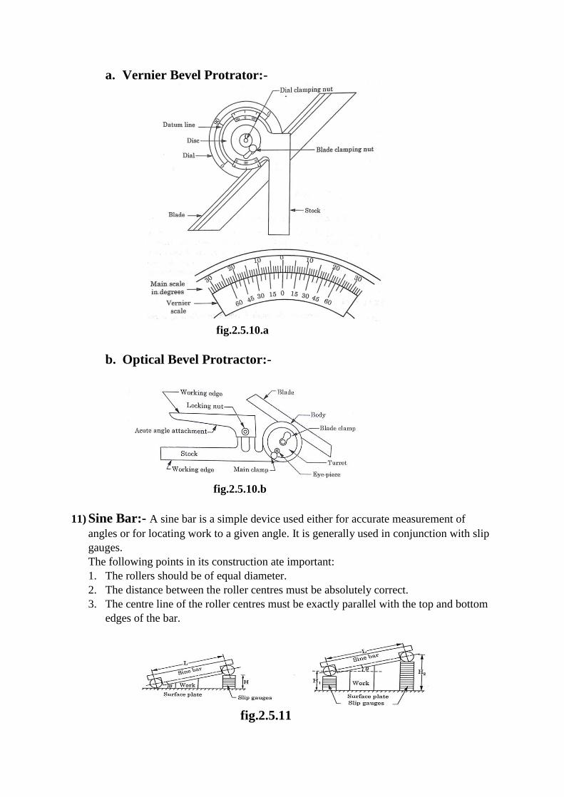
a. Vernier Bevel Protrator:-
fig.2.5.10.a
b. Optical Bevel Protractor:-
fig.2.5.10.b
11) Sine Bar:- A sine bar is a simple device used either for accurate measurement of
angles or for locating work to a given angle. It is generally used in conjunction with slip
gauges.
The following points in its construction ate important:
1. The rollers should be of equal diameter.
2. The distance between the roller centres must be absolutely correct.
3. The centre line of the roller centres must be exactly parallel with the top and bottom
edges of the bar.
fig.2.5.11

12) Tool Room Microscope:- A tool room microscope is a versatile instrument which
measures by optical means with no pressure involved.
fig.2.5.12
13) Profile Projector:- It is also known as magic lantern. It is used to protect a magnified
image of a small transparent object like a photographic film or a slide on a screen. It
produces a real, inverted and magnified image of the object on the screen of an
arrangement of lenses.
fig.2.5.13
14) Gauges:- these are generally used to check the particular dimension of a work piece
within its tolerance.
15) Plug gauges:- These are used to check holes of different shapes and sizes. Plug gauges
are available to check straight cylindrical holes, tapered, threaded and splined holes.
fig.2.5.15

16) Screw Pitch Gauges:- These are used to check the pitch of screws.
fig.2.5.16

CHAPTER-3 STATISTICAL QUALITY CONTROL
3.1 Statistics:- Statistics means data, a good amount of data to obtain reliable results.
Statistics is thus concerned with the collection, organization, analysis, interpretation and
presentation of data for use.
3.2 Quality:- A component may be said to possess good quality if it works well in the
machine for which kit has been made.
3.3 Control:- Control is a system for measuring and checking a phenomenon.
3.4 Basic Statistical Terms:-
1) Average:- The average is calculated by adding all the numbers or observations and
dividing the sum by the number of observations. It is also known as arithmetic mean.
2) Average of Frequency Distribution:- The average is used as a representative
of a group if each item of a group differs from the other.
3) Median:- When different items in a group are arranged in ascending or descending
order, the middle number of the series is known as median which represents the
group.
4) Mode:- It is the most common value in the group repeating largest number of times.
3.5 Frequency Distribution:- It is a term used to denote a method or system of
tabulation of the data or values obtained from the actual measurement of parts, the values or
data being arranged in either ascending or descending order.
1) Frequency Histogram:- It is a graph consisting of a number of vertical columns
called cells. The vertical height of each column represents the frequency while the
sides of each column represent the upper and lower boundaries of the cell.
fig.3.5.1

2) Bar Chart:- In this graph, vertical bars are drawn at the mid-points of the cells.
fig.3.5.2
3) Frequency Polygon:- In this graph, small circles are drawn with the terminal free
ends of the ends of the bars as centres.
fig.3.5.3
3.6 Normal Distribution:- It is also known as Gaussian distribution. This distribution
has a symmetrical bell-shaped form and tends to infinity in both directions.
fig.3.6

3.7 Control charts:- A control chart may be described as a graphical representation of
the information gathered during inspection of products with respect to their quality
characteristics.
3.7.1 Types of Control Charts:-
The following two types of control charts are usually used:
1. Control charts for variables
2. Control charts for attributes
3.7 Sampling Plans:- A sampling plan may be defined as a statement of sampling
procedure and rules for making inference about the lot.
3.7.1 Types of Sampling Plans:-
1) Single Sampling Plan:-
fig.3.7.1
2) Double Sampling plan:-
fig.3.7.2
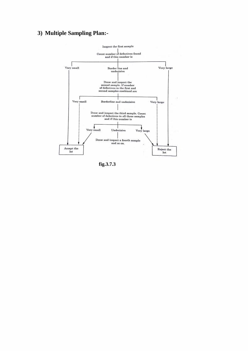
3) Multiple Sampling Plan:-
fig.3.7.3
CHAPTER-4 MODERN QUALITY CONCEPTS
4.1 CONCEPT OF TOTAL QUALITY MANAGEMENT (TQM):-
TQM may be defined as creating an organizational culture committed to the continuous
improvement of skills, team work, processes, product and service quality and customer
satisfaction.
4.2 Necessity of TQM:-
The necessity of TQM is for the following reasons:
1. To build and develop best organization.
2. To call into play potential of human capabilities.
3. To continuously reduce cost.
4. To build a happy bright place.
5. To develop problem solving skills.
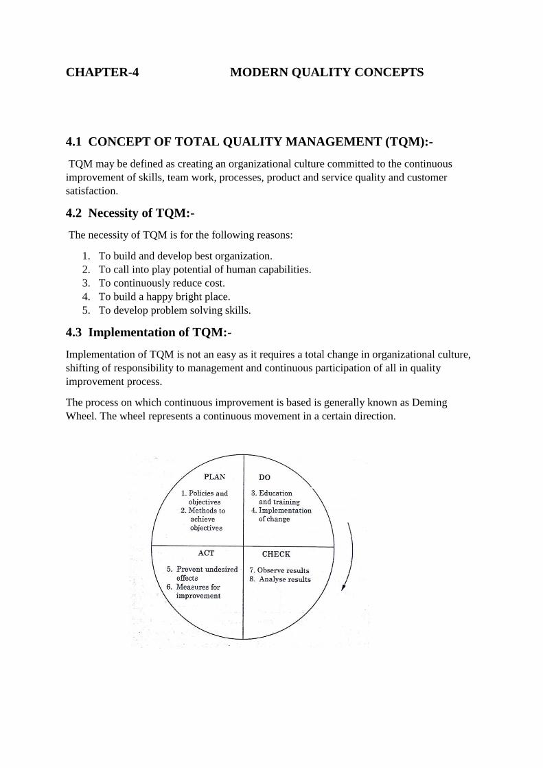
4.3 Implementation of TQM:-
Implementation of TQM is not an easy as it requires a total change in organizational culture,
shifting of responsibility to management and continuous participation of all in quality
improvement process.
The process on which continuous improvement is based is generally known as Deming
Wheel. The wheel represents a continuous movement in a certain direction.

The process of implementing TQM in an organization can be organized in the following four
stages:
1. Identification and preparation
2. Management understanding
3. Scheme for improvement
4. Critical analysis
4.4 TQM Model:-
Customer satisfaction is the focus of TQM. Basically, the customer satisfaction depends
upon the gap between the expected and actually quality of products offered by the company.
The model shows the implementation of TQM benefits the company in both long and short
term and in turn, achieves the customer satisfaction.
4.5 International Codes/Standards:-
ISO prepared a document called ISO 9000 series in 1987 as a guidelines for all organizations
on managing quality and standards. Structure of quality system standards is shown in fig.

4.6 Quality Control Tools:-
Most organizations use quality control tools for various purposes related to controlling and
assuring quality. Although there are various quality control tools are:
1) Flow chart: This is one of the basic quality control tool which maps out a sequence
of events that place sequentially and analyses them.
2) Histogram:It is used to illustrate the frequency and the extent in the context of two
variables. It is a chart with columns. It represents the distribution by mean.

3) Cause and Effect Diagram: It is used to understand the causes of organization
or business problems. All the main components of the problem areas along with its
possible causes are listed.
4) Check Sheet: It is basically used for gathering and organizing data. When it is
made with the help of software packages.
5) Scatter Diagram: Scatter diagram represents the relationship between two
variables and illustrates the results on a Cartesian plane.

6) Control Chart: These charts allow us to identify the following conditions related
to the process that has been monitored:
(i.) Stability of the process.
(ii.) Predictability of the process.
(iii.) Identification of common causes of variation.
(iv.) Special conditions where the monitoring party needs to react.
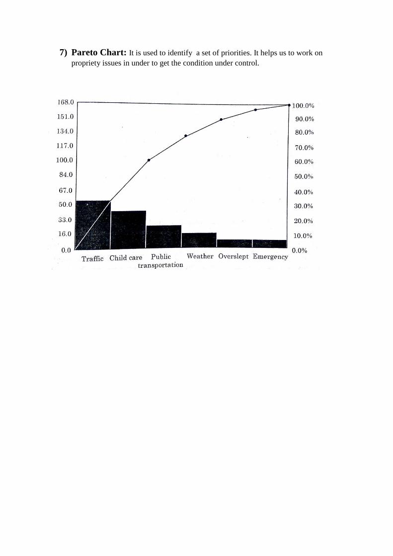
7) Pareto Chart: It is used to identify a set of priorities. It helps us to work on
propriety issues in under to get the condition under control.

CHAPTER-5 INSTRUMENTATION
5.1 Transducer:-
A transducer is a device which converts the energy from one form into another form. Most of
the transducers either convert electrical energy into mechanical displacement and/or convert
some non-electrical physical quantity.
fig.5.1
5.1.1 Classification of Transducers:
(A.) Classification Based on the Type of Output: 1. Analog Transducer
2. Digital Transducer
(B.) Classification Based on the Source of Energy:
1. Active Transducer
2. Passive Transducer
(C.) Classification Based on Electrical Principle Involved: 1. Variable Resistance Type
2. Variable Inductance Type
3. Variable Capacitance Type
4. Voltage Generating Type
5. Voltage Divider Type
5.2 Transducer Sensitivity:-
It may be defined as the relationship between measured and transducer output signal. It must
be as high as possible.

5.3 Measurement of Displacement:-
1) Resistive Potentiometer: It converts linear or angular displacements into change
in resistance.
fig.5.3.1
2) Variable Inductance Transducer:
(i.) Self-generating Type
Electromagnetic type Electrodynamic Type
fig.5.3.2.i

(ii.) Passive Type
Mutual Inductance Type
fig.5.3.2.ii
5.4 Measurement of Frequency:
It can measure frequencies over a wide range. In this instrument, the saturable core
transformer acts as a primary detector.
fig.5.4
5.5 Measurement of Pressure: The pressure can be measured with the help of
following transducers:
1) Resistance Type Pressure Transducer: Strain gauge is an example of
resistance type transducer. The strain gauge works on the principle that when a metal

conductor is stretched or compressed, its resistance changes due to the fact that both
its length and diameter change.
fig.5.5.1
2) Inductance Type Pressure Transducer: The inductance type pressure
transducer consists of one primary winding and two secondary windings. The primary
winding is mounted on the movable magnetic core.
fig.5.5.2
5.6 Measurement of Temperature:
The temperature can be measured with the help of following transducers:
1) Resistance Thermometer: This transducer works on the principle that the electrical
resistance of the metal increases with the increases in temperature.
2) Thermocouple Thermometer: This thermometer works on the principle that when
two dissimilar metal conductors are joined at the ends keeping the junctions at
different temperatures, a small e.m.f. is produced in the circuit.

fig.5.6